Embed Size (px)
Citation preview
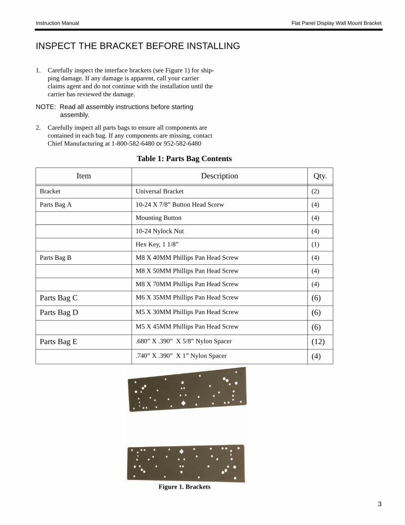
Instruction Manual Flat Panel Display Wall Mount Bracket
5
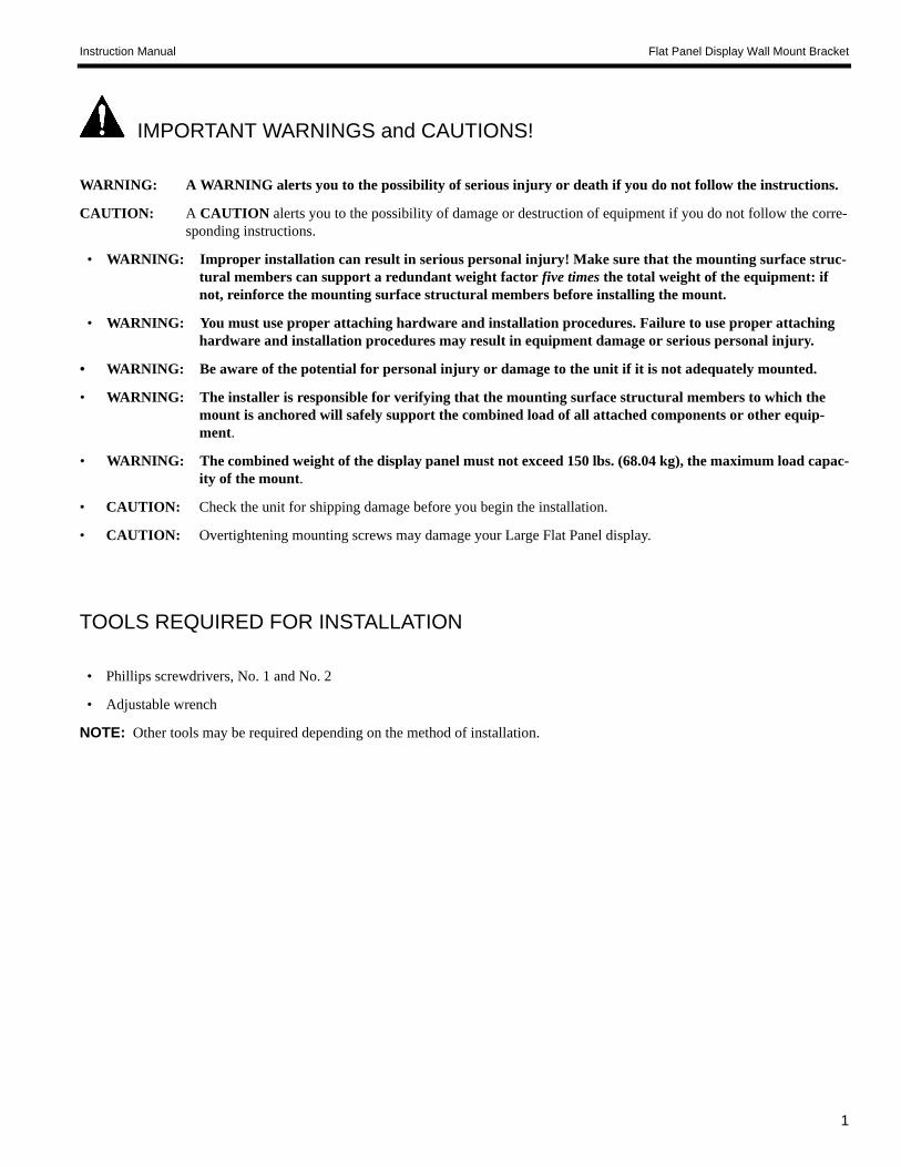
ATTACH MOUNTING BUTTONS
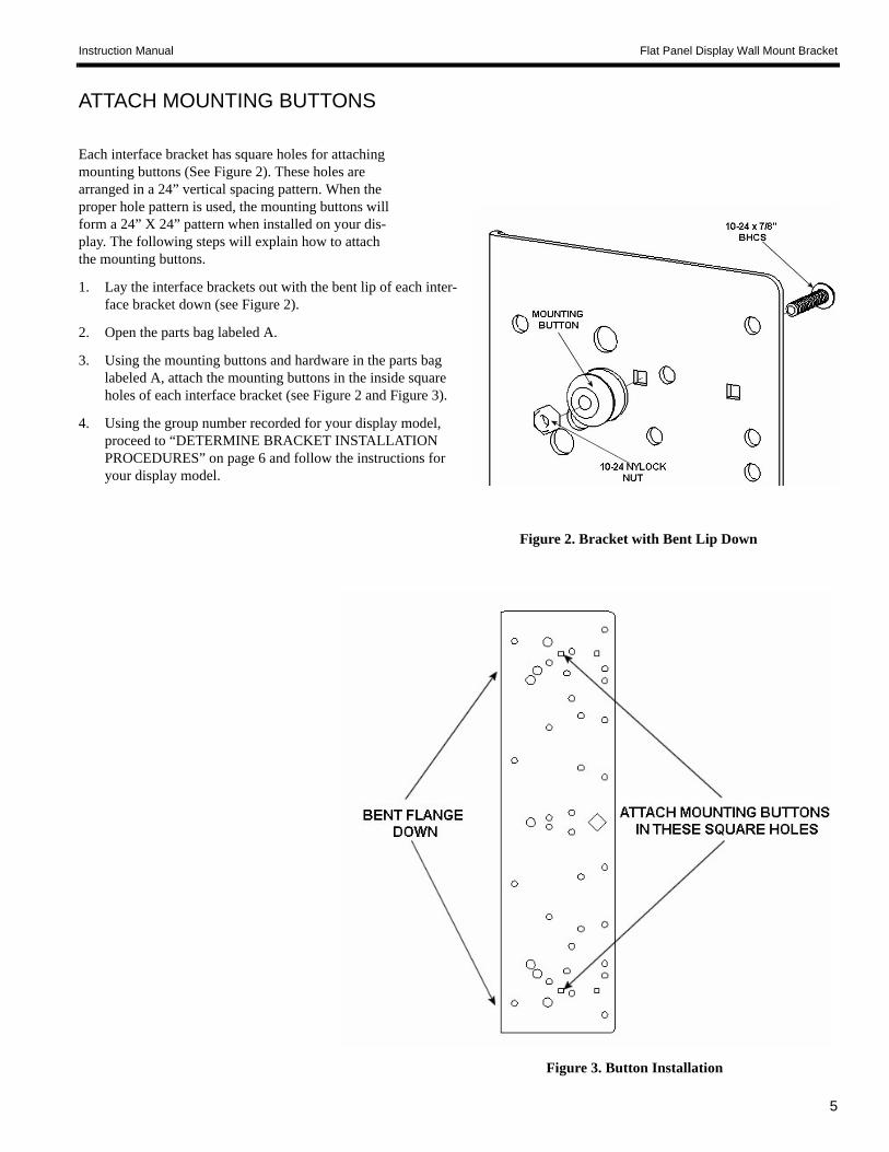
Each interface bracket has square holes for attaching mounting buttons (See Figure 2). These holes are arranged in a 24” vertical spacing pattern. When the proper hole pattern is used, the mounting buttons will form a 24” X 24” pattern when installed on your dis-play. The following steps will explain how to attach the mounting buttons.
1. Lay the interface brackets out with the bent lip of each inter-face bracket down (see Figure 2).
2. Open the parts bag labeled A.
3. Using the mounting buttons and hardware in the parts bag labeled A, attach the mounting buttons in the inside square holes of each interface bracket (see Figure 2 and Figure 3).
4. Using the group number recorded for your display model, proceed to “DETERMINE BRACKET INSTALLATION PROCEDURES” on page 6 and follow the instructions for your display model.
Figure 2. Bracket with Bent Lip Down
Figure 3. Button Installation
6
Instruction Manual Universal Flat Panel Display Wall Mount Bracket
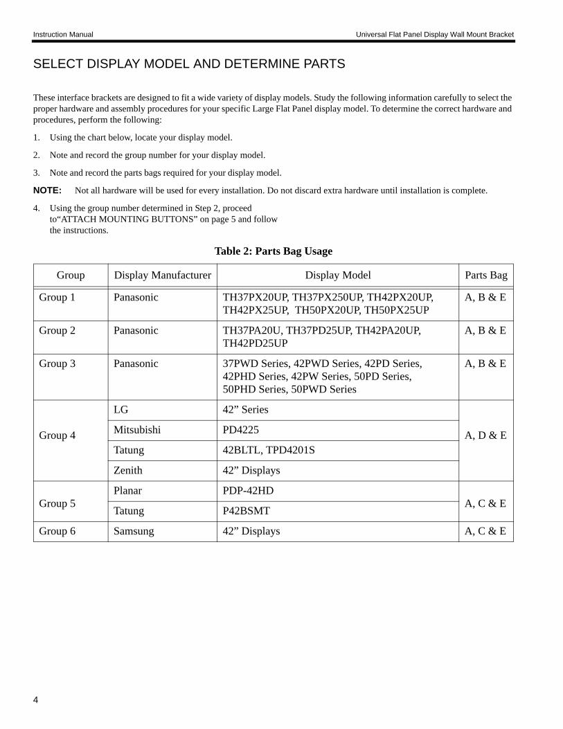
DETERMINE BRACKET INSTALLATION PROCEDURES
Group 1 Installation ProceduresWARNING: You must use proper attaching hardware and
installation procedures. Failure to use proper attaching hardware and installation procedures may result in equipment damage or serious per-sonal injury.
Attach Interface Brackets
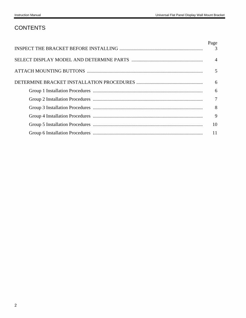
1. Identify and select the parts bags labeled B and E.
2. Remove the Nylon spacers from the parts bag labeled E.
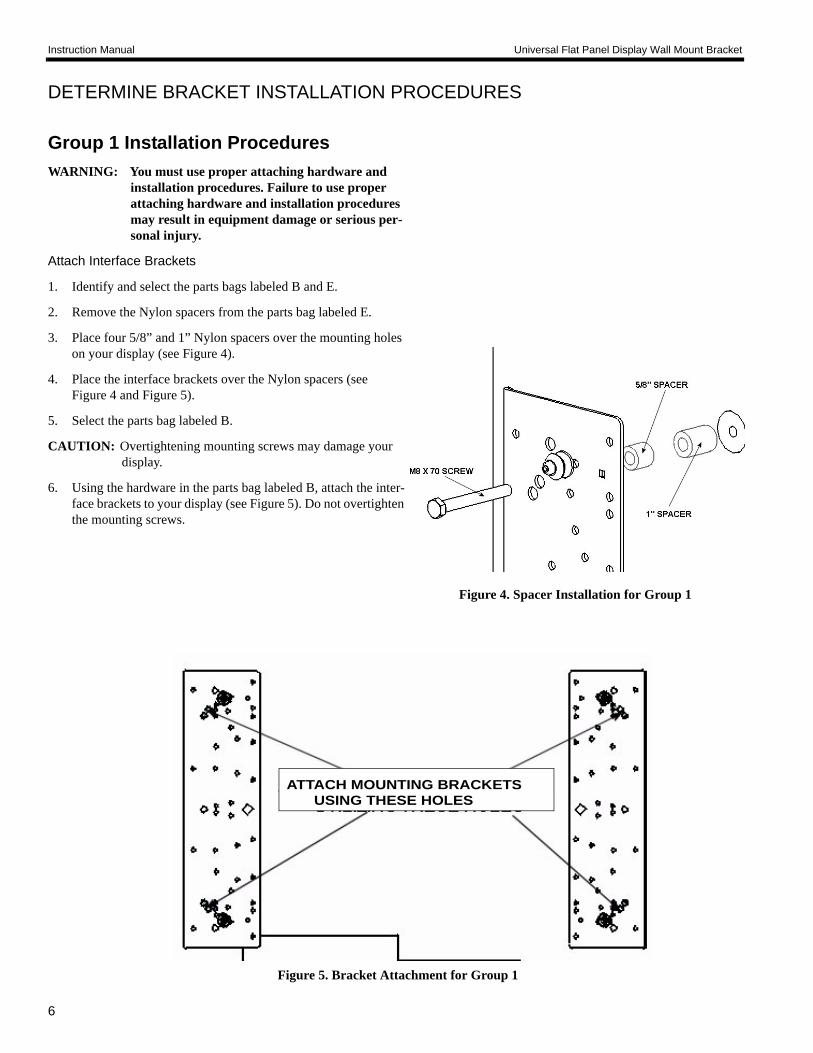
3. Place four 5/8” and 1” Nylon spacers over the mounting holes on your display (see Figure 4).
4. Place the interface brackets over the Nylon spacers (see Figure 4 and Figure 5).
5. Select the parts bag labeled B.
CAUTION: Overtightening mounting screws may damage your display.
6. Using the hardware in the parts bag labeled B, attach the inter-face brackets to your display (see Figure 5). Do not overtighten the mounting screws.
ATTACH MOUNTING BRACKETSUSING THESE HOLES
Figure 4. Spacer Installation for Group 1
Figure 5. Bracket Attachment for Group 1
Instruction Manual Flat Panel Display Wall Mount Bracket
7
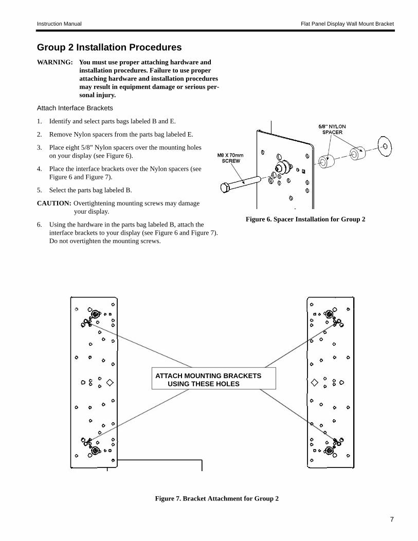
Group 2 Installation ProceduresWARNING: You must use proper attaching hardware and
installation procedures. Failure to use proper attaching hardware and installation procedures may result in equipment damage or serious per-sonal injury.
Attach Interface Brackets
1. Identify and select parts bags labeled B and E.
2. Remove Nylon spacers from the parts bag labeled E.
3. Place eight 5/8” Nylon spacers over the mounting holes on your display (see Figure 6).
4. Place the interface brackets over the Nylon spacers (see Figure 6 and Figure 7).
5. Select the parts bag labeled B.
CAUTION: Overtightening mounting screws may damage your display.
6. Using the hardware in the parts bag labeled B, attach the interface brackets to your display (see Figure 6 and Figure 7). Do not overtighten the mounting screws.
Figure 6. Spacer Installation for Group 2
ATTACH MOUNTING BRACKETSUSING THESE HOLES
Figure 7. Bracket Attachment for Group 2
8
Instruction Manual Universal Flat Panel Display Wall Mount Bracket
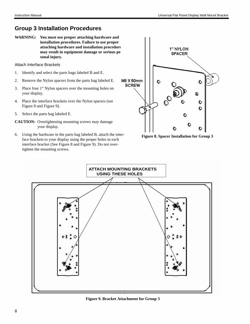
Group 3 Installation ProceduresWARNING: You must use proper attaching hardware and
installation procedures. Failure to use proper attaching hardware and installation procedures may result in equipment damage or serious per-sonal injury.
Attach Interface Brackets
1. Identify and select the parts bags labeled B and E.
2. Remove the Nylon spacers from the parts bag labeled E.
3. Place four 1” Nylon spacers over the mounting holes on your display.
4. Place the interface brackets over the Nylon spacers (see Figure 8 and Figure 9).
5. Select the parts bag labeled E.
CAUTION: Overtightening mounting screws may damage your display.
6. Using the hardware in the parts bag labeled B, attach the inter-face brackets to your display using the proper holes in each interface bracket (See Figure 8 and Figure 9). Do not over-tighten the mounting screws.
Figure 9. Bracket Attachment for Group 3
ATTACH MOUNTING BRACKETSUSING THESE HOLES
Figure 8. Spacer Installation for Group 3
Instruction Manual Flat Panel Display Wall Mount Bracket
9
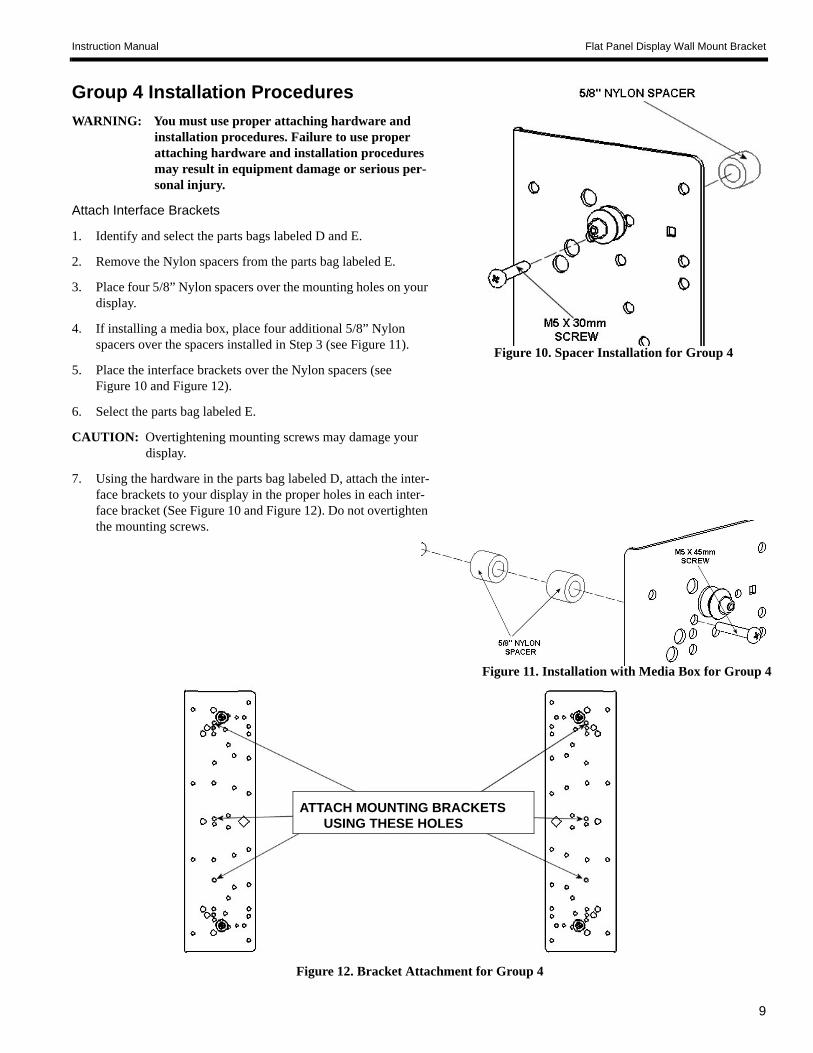
Group 4 Installation ProceduresWARNING: You must use proper attaching hardware and
installation procedures. Failure to use proper attaching hardware and installation procedures may result in equipment damage or serious per-sonal injury.
Attach Interface Brackets
1. Identify and select the parts bags labeled D and E.
2. Remove the Nylon spacers from the parts bag labeled E.
3. Place four 5/8” Nylon spacers over the mounting holes on your display.
4. If installing a media box, place four additional 5/8” Nylon spacers over the spacers installed in Step 3 (see Figure 11).
5. Place the interface brackets over the Nylon spacers (see Figure 10 and Figure 12).
6. Select the parts bag labeled E.
CAUTION: Overtightening mounting screws may damage your display.
7. Using the hardware in the parts bag labeled D, attach the inter-face brackets to your display in the proper holes in each inter-face bracket (See Figure 10 and Figure 12). Do not overtighten the mounting screws.
Figure 10. Spacer Installation for Group 4
ATTACH MOUNTING BRACKETSUSING THESE HOLES
Figure 12. Bracket Attachment for Group 4
Figure 11. Installation with Media Box for Group 4
10
Instruction Manual Universal Flat Panel Display Wall Mount Bracket
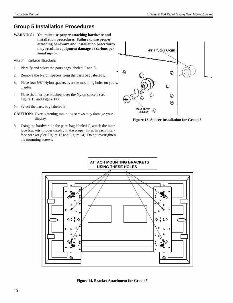
Group 5 Installation ProceduresWARNING: You must use proper attaching hardware and
installation procedures. Failure to use proper attaching hardware and installation procedures may result in equipment damage or serious per-sonal injury.
Attach Interface Brackets
1. Identify and select the parts bags labeled C and E.
2. Remove the Nylon spacers from the parts bag labeled E.
3. Place four 5/8” Nylon spacers over the mounting holes on your display.
4. Place the interface brackets over the Nylon spacers (see Figure 13 and Figure 14).
5. Select the parts bag labeled E.
CAUTION: Overtightening mounting screws may damage your display.
6. Using the hardware in the parts bag labeled C, attach the inter-face brackets to your display in the proper holes in each inter-face bracket (See Figure 13 and Figure 14). Do not overtighten the mounting screws.
Figure 13. Spacer Installation for Group 5
Figure 14. Bracket Attachment for Group 5
ATTACH MOUNTING BRACKETSUSING THESE HOLES
Instruction Manual Flat Panel Display Wall Mount Bracket
11
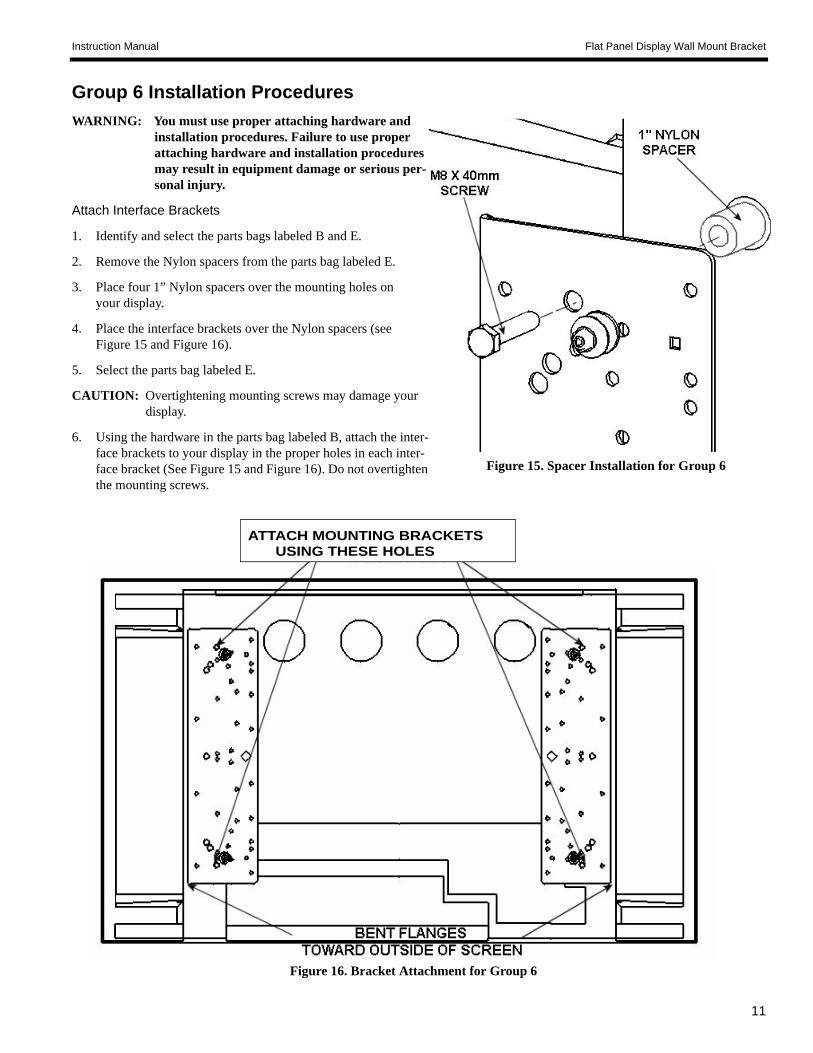
Group 6 Installation ProceduresWARNING: You must use proper attaching hardware and
installation procedures. Failure to use proper attaching hardware and installation procedures may result in equipment damage or serious per-sonal injury.
Attach Interface Brackets
1. Identify and select the parts bags labeled B and E.
2. Remove the Nylon spacers from the parts bag labeled E.
3. Place four 1” Nylon spacers over the mounting holes on your display.
4. Place the interface brackets over the Nylon spacers (see Figure 15 and Figure 16).
5. Select the parts bag labeled E.
CAUTION: Overtightening mounting screws may damage your display.
6. Using the hardware in the parts bag labeled B, attach the inter-face brackets to your display in the proper holes in each inter-face bracket (See Figure 15 and Figure 16). Do not overtighten the mounting screws.
Figure 15. Spacer Installation for Group 6
Figure 16. Bracket Attachment for Group 6
ATTACH MOUNTING BRACKETSUSING THESE HOLES

12
Instruction Manual Universal Flat Panel Display Wall Mount Bracket