Embed Size (px)
Citation preview
© Copyright 2019 WIZnet Co., Ltd. All rights reserved.
W6100 Hardwired Dual TCP/IP Stack Controller
V1.0.0
http://www.wiznet.io/
W6100 – Hardwired Dual TCP/IP Stack Controller 2/149
W6100
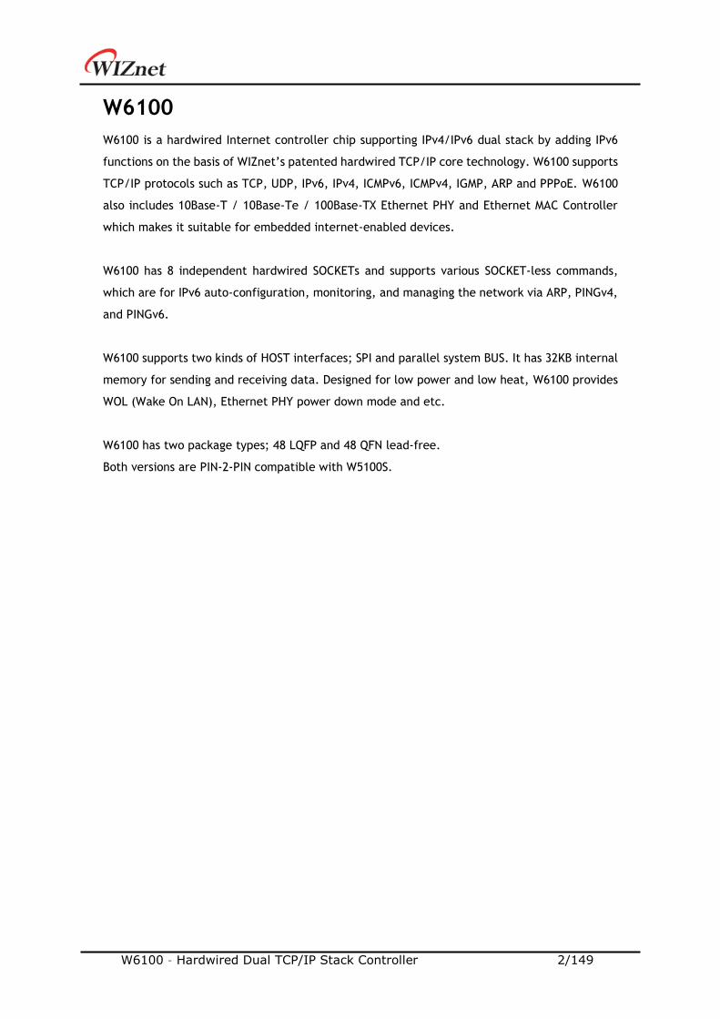
W6100 is a hardwired Internet controller chip supporting IPv4/IPv6 dual stack by adding IPv6
functions on the basis of WIZnet’s patented hardwired TCP/IP core technology. W6100 supports
TCP/IP protocols such as TCP, UDP, IPv6, IPv4, ICMPv6, ICMPv4, IGMP, ARP and PPPoE. W6100
also includes 10Base-T / 10Base-Te / 100Base-TX Ethernet PHY and Ethernet MAC Controller
which makes it suitable for embedded internet-enabled devices.
W6100 has 8 independent hardwired SOCKETs and supports various SOCKET-less commands,
which are for IPv6 auto-configuration, monitoring, and managing the network via ARP, PINGv4,
and PINGv6.
W6100 supports two kinds of HOST interfaces; SPI and parallel system BUS. It has 32KB internal
memory for sending and receiving data. Designed for low power and low heat, W6100 provides
WOL (Wake On LAN), Ethernet PHY power down mode and etc.
W6100 has two package types; 48 LQFP and 48 QFN lead-free.
Both versions are PIN-2-PIN compatible with W5100S.
W6100 – Hardwired Dual TCP/IP Stack Controller 3/149
Features
- Supports hardwired TCP/IP protocols
: TCP, UDP, IPv6, IPv4, ICMPv6, ICMPv4, IGMP, MLDv1, ARP, PPPoE
- Supports IPv4/IPv6 dual stack
- Supports 8 independent SOCKETs simultaneously with 32KB memory
- Supports SOCKET-less commands
: ARP, ICMPv6 (ARP, DAD, NA, RS) command for IPv6 auto-configuration & network
monitoring (PING, PING6)
- Supports Ethernet PHY power down mode & system clock switching for power save
- Supports wake on LAN over UDP
- Supports serial & parallel HOST interface
: High speed SPI (MODE 0/3), system BUS with 2 address signal & 8bit data
- Internal 32Kbytes memory for TX/ RX Buffers
- 10BaseT/ 10BaseTe / 100BaseTX Ethernet PHY integrated
- Supports auto negotiation (full/half duplex, 10 and 100-based)
- Supports auto-MDIX only on auto-negotiation mode
- Does not support IP fragmentation & jumbo packet
- 3V operation with 5V I/O signal tolerance
- Network indicator LEDs (full/half duplex, link, 10/100 speed, active)
- 48 Pin LQFP & QFN lead-free package (7x7mm, 0.5mm pitch)
- PIN-2-PIN compatible with W5100S
Target Applications
W6100 can be used in various applications.
- Home network devices: set-top boxes, PVRs, digital media adapters
- Serial-to-Ethernet: access control, LED display, wireless AP relay
- Parallel-to-Ethernet: POS / mini printers, copy machine
- USB-to-Ethernet: storage devices, network printers
- GPIO-to-Ethernet: Home network sensors
- Security systems: DVR, network cameras, kiosks
- Factory & home automation
- Medical monitoring equipment
- Embedded servers
- Internet of Thing (IoT) devices
- IoT cloud devices
- Etc
W6100 – Hardwired Dual TCP/IP Stack Controller 4/149
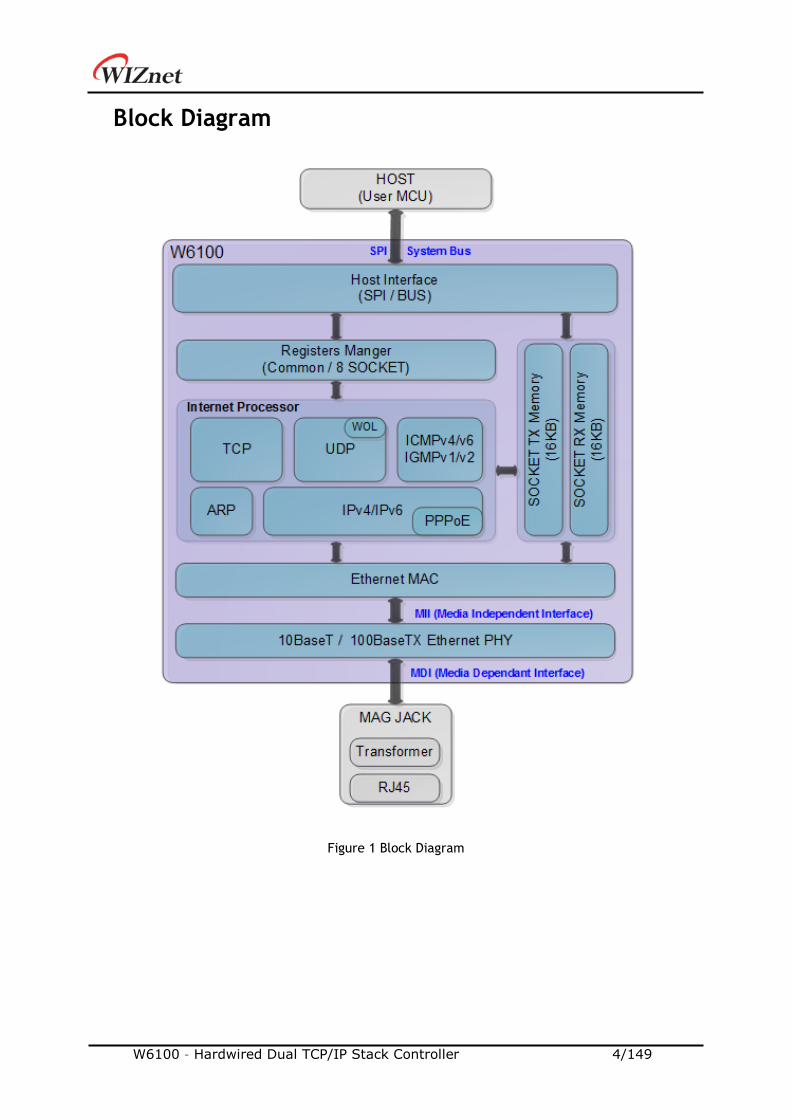
Block Diagram
Figure 1 Block Diagram
W6100 – Hardwired Dual TCP/IP Stack Controller 5/149
Contents
1. PIN Description ........................................................................................ 12
1.1 PIN Description ........................................................................... 13
2. Memory Map ............................................................................................ 17
3. W6100 Registers ....................................................................................... 19
3.1 Common Register ........................................................................ 19
3.2 SOCKET Register .......................................................................... 25
4. Register Descriptions ................................................................................. 27
4.1 Common Registers ....................................................................... 28
4.1.1 CIDR (Chip Identification Register) ................................................... 28
4.1.2 VER (Version Register) ................................................................. 28
4.1.3 SYSR (System Status Register) ........................................................ 28
4.1.4 SYCR0 (System Config Register 0) .................................................... 29
4.1.5 SYCR1 (System Config Register 1) .................................................... 30
4.1.6 TCNTR (Tick Counter Register) ....................................................... 30
4.1.7 TCNTRCLR (TCNTR Clear Register) ................................................... 30
4.1.8 IR (Interrupt Register) .................................................................. 30
4.1.9 SIR (SOCKET Interrupt Register) ...................................................... 31
4.1.10 SLIR (SOCKET-less Interrupt Register) .............................................. 32
4.1.11 IMR (Interrupt Mask Register) ........................................................ 33
4.1.12 IRCLR (IR Clear Register) ............................................................. 34
4.1.13 SIMR (SOCKET Interrupt Mask Register) ............................................ 34
4.1.14 SLIMR (SOCKET-less Interrupt Mask Register) ...................................... 34
4.1.15 SLIRCLR (SLIR Clear Register) ........................................................ 35
4.1.16 SLPSR (SOCKET-less Prefer Source IPv6 Address Register) ....................... 35
4.1.17 SLCR (SOCKET-less Command Register) ............................................ 36
4.1.18 PHYSR (PHY Status Register) ......................................................... 37
4.1.19 PHYRAR (PHY Register Address Register) .......................................... 37
4.1.20 PHYDIR (PHY Data Input Register) .................................................. 38
4.1.21 PHYDOR (PHY Data Output Register) ............................................... 38
4.1.22 PHYACR (PHY Access Control Register) ............................................. 38
4.1.23 PHYDIVR (PHY Division Register) .................................................... 38
4.1.24 PHYCR0 (PHY Control Register 0) ................................................... 39
4.1.25 PHYCR1 (PHY Control Register 1) ................................................... 39
4.1.26 NET4MR (Network IPv4 Mode Register) ............................................. 40
4.1.27 NET6MR (Network IPv6 Mode Register) ............................................. 41
4.1.28 NETMR (Network Mode Register) .................................................... 42
4.1.29 NETMR2 (Network Mode Register 2) ................................................ 43
W6100 – Hardwired Dual TCP/IP Stack Controller 6/149
4.1.30 PTMR (PPP Link Control Protocol Request Timer Register) ...................... 43
4.1.31 PMNR (PPP Link Control Protocol Magic number Register) ...................... 43
4.1.32 PHAR (PPPoE Server Hardware Address Register on PPPoE) ..................... 44
4.1.33 PSIDR (PPPoE Session ID Register on PPPoE) ....................................... 44
4.1.34 PMRUR (PPPoE Maximum Receive Unit Register).................................. 44
4.1.35 SHAR (Source Hardware Address Register) ......................................... 44
4.1.36 GAR (Gateway IP Address Register) ................................................. 45
4.1.37 SUBR (Subnet Mask Register) ........................................................ 45
4.1.38 SIPR (IPv4 Source Address Register) ................................................ 45
4.1.39 LLAR (Link Local Address Register) ................................................. 46
4.1.40 GUAR (Global Unicast Address Register) ........................................... 46
4.1.41 SUB6R (IPv6 Subnet Prefix Register) ................................................ 46
4.1.42 GA6R (IPv6 Gateway Address Register) ............................................. 47
4.1.43 SLDIP6R (SOCKET-less Destination IPv6 Address Register) ....................... 47
4.1.44 SLDIPR (SOCKET-less Destination IPv4 Address Register) ........................ 47
4.1.45 SLDHAR (SOCKET-less Destination Hardware Address Register) ................ 48
4.1.46 PINGIDR (PING ID Register) ........................................................... 48
4.1.47 PINGSEQR (PING Sequence-number Register) ..................................... 48
4.1.48 UIPR (Unreachable IP Address Register) ............................................ 49
4.1.49 UPORTR (Unreachable Port Register) ............................................... 49
4.1.50 UIP6R (Unreachable IPv6 Address Register) ....................................... 49
4.1.51 UPORT6R (Unreachable IPv6 Port Register)........................................ 49
4.1.52 INTPTMR (Interrupt Pending Time Register) ....................................... 50
4.1.53 PLR (Prefix Length Register) ......................................................... 50
4.1.54 PFR (Prefix Flag Register) ............................................................ 50
4.1.55 VLTR (Valid Life Time Register) ..................................................... 50
4.1.56 PLTR (Preferred Life Time Register) ................................................ 51
4.1.57 PAR (Prefix Address Register) ........................................................ 51
4.1.58 ICMP6BLKR (ICMPv6 Block Register) ................................................ 51
4.1.59 CHPLCKR (Chip Lock Register) ....................................................... 52
4.1.60 NETLCKR (Network Lock Register) .................................................. 52
4.1.61 PHYLCKR (PHY Lock Register) ....................................................... 52
4.1.62 RTR (Retransmission Time Register) ................................................ 53
4.1.63 RCR (Retransmission Count Register) ............................................... 53
4.1.64 SLRTR (SOCKET-less Retransmission Time Register) .............................. 53
4.1.65 SLRCR (SOCKET-less Retransmission Count Register) ............................. 54
4.1.66 SLHOPR (Hop limit Register) ......................................................... 54
4.2 SOCKET Register .......................................................................... 55
4.2.1 Sn_MR (SOCKET n Mode Register) .................................................... 55

W6100 – Hardwired Dual TCP/IP Stack Controller 7/149
4.2.2 Sn_PSR (SOCKET n Prefer Source IPv6 Address Register) .......................... 57
4.2.3 Sn_CR (SOCKET n Command Register) ............................................... 57
4.2.4 Sn_IR (SOCKET n Interrupt Register) ................................................. 60
4.2.5 Sn_IMR (SOCKET n Interrupt Mask Register) ......................................... 60
4.2.6 Sn_IRCLR (Sn_IR Clear Register) ...................................................... 61
4.2.7 Sn_SR (SOCKET n Status Register) .................................................... 61
4.2.8 Sn_ESR (SOCKET n Extension Status Register) ...................................... 62
4.2.9 Sn_PNR (SOCKET n IP Protocol Number Register) .................................. 63
4.2.10 Sn_TOSR (SOCKET n IP Type of Service Register) ................................. 63
4.2.11 Sn_TTLR (SOCKET n IP Time To Live Register) .................................... 63
4.2.12 Sn_FRGR (SOCKET n Fragment Offset in IP Header Register) ................... 63
4.2.13 Sn_MSSR (SOCKET n Maximum Segment Size Register) ........................... 64
4.2.14 Sn_PORTR (SOCKET n Source Port Register) ....................................... 64
4.2.15 Sn_DHAR (SOCKET n Destination Hardware Address Register) .................. 65
4.2.16 Sn_DIPR (SOCKET n Destination IPv4 Address Register) .......................... 65
4.2.17 Sn_DIP6R (SOCKET n Destination IPv6 Address Register) ........................ 65
4.2.18 Sn_DPORTR (SOCKET n Destination Port Register) ................................ 66
4.2.19 Sn_MR2 (SOCKET n Mode register 2) ................................................ 67
4.2.20 Sn_RTR (SOCKET n Retransmission Time Register) ............................... 68
4.2.21 Sn_RCR (SOCKET n Retransmission Count Register) .............................. 68
4.2.22 Sn_KPALVTR (SOCKET n Keep Alive Time Register) ............................... 68
4.2.23 Sn_TX_BSR (SOCKET n TX Buffer Size Register) ................................... 68
4.2.24 Sn_TX_FSR (SOCKET n TX Free Buffer Size Register) ............................. 69
4.2.25 Sn_TX_RD (SOCKET n TX Read Pointer Register) .................................. 69
4.2.26 Sn_TX_WR (SOCKET n TX Write Pointer Register) ................................ 70
4.2.27 Sn_RX_BSR (SOCKET n RX Buffer Size Register) ................................... 70
4.2.28 Sn_RX_RSR (SOCKET n RX Received Size Register) ................................ 70
4.2.29 Sn_RX_RD (SOCKET n RX Read Pointer Register) .................................. 71
4.2.30 Sn_RX_WR (SOCKET n RX Write Pointer Register) ................................ 71
5. HOST Interface Mode ................................................................................. 72
5.1 SPI Mode ................................................................................... 72
5.1.1 SPI Frame ................................................................................ 73
5.1.2 Variable Length Data Mode (VDM) .................................................... 76
5.1.3 Fixed Length Data Mode (FDM)........................................................ 77
5.2 Parallel BUS Mode ........................................................................ 80
5.2.1 Parallel BUS Data Write ................................................................ 81
5.2.2 Parallel BUS Data Read ................................................................. 82
6. Functional Description ............................................................................... 83
6.1 Initialization .............................................................................. 83
W6100 – Hardwired Dual TCP/IP Stack Controller 8/149
6.1.1 Network Information Setting .......................................................... 83
6.1.2 SOCKET TX/RX Buffer Size Setting ................................................... 84
6.2 TCP ......................................................................................... 85
6.2.1 TCP SERVER .............................................................................. 86
6.2.2 TCP CLIENT .............................................................................. 93
6.2.3 TCP DUAL ................................................................................ 94
6.2.4 Other Functions ......................................................................... 96
6.3 UDP ......................................................................................... 98
6.3.1 UDP Unicast .............................................................................. 98
6.3.2 UDP Broadcast ......................................................................... 102
6.3.3 UDP Multicast .......................................................................... 104
6.3.4 UDP DUAL .............................................................................. 106
6.3.5 Other Functions ....................................................................... 108
6.4 IPRAW .................................................................................... 109
6.4.1 Other Functions ....................................................................... 114
6.5 MACRAW ................................................................................. 115
6.6 SOCKET-less Command (SLCR)........................................................ 117
6.6.1 ARP 117
6.6.2 PING .................................................................................... 119
6.6.3 ARP6 (ND, Neighbor Discovery) ..................................................... 121
6.6.4 PING6 (ICMPv6 Echo) ................................................................. 122
6.6.5 DAD (Duplicate Address Detection) ................................................ 124
6.6.6 RS (Router Solicitation) .............................................................. 126
6.6.7 Unsolicited NA(Neighbor Advertisement) .......................................... 128
6.7 Retransmission .......................................................................... 130
6.7.1 ARP & PING & ND Retransmission ................................................... 130
6.7.2 TCP Retransmission ................................................................... 131
6.8 Others Functions ....................................................................... 132
6.8.1 System Clock(SYS_CLK) Switching .................................................. 132
6.8.2 Ethernet PHY Operation Mode Configuration ..................................... 132
6.8.3 Ethernet PHY Parallel Detection .................................................... 133
6.8.4 Ethernet PHY Auto MDIX ............................................................. 133
6.8.5 Ethernet PHY Power Down Mode ................................................... 133
6.8.6 Ethernet PHY’s Registers Control ................................................... 135
6.8.7 Ethernet PHY 10BASE-Te Mode...................................................... 137
7. Clock & Transformer Requirements ............................................................. 138
7.1 Quartz Crystal Requirements. ........................................................ 138
7.2 Oscillator requirements. .............................................................. 139
7.3 Transformer Characteristics .......................................................... 139
W6100 – Hardwired Dual TCP/IP Stack Controller 9/149
8. Electrical Specification ............................................................................ 140
8.1 Absolute Maximum ratings ............................................................ 140
8.2 Absolute Maximum ratings (Electrical Sensitivity)................................. 140
8.3 DC Characteristics ..................................................................... 141
8.4 AC Characteristics ...................................................................... 142
8.4.1 Reset Timing ........................................................................... 142
8.4.2 BUS ACCESS TIMING ................................................................... 143
8.4.3 SPI ACCESS TIMING .................................................................... 144
8.4.4 Transformer Characteristics ......................................................... 145
8.4.5 MDIX .................................................................................... 145
8.5 POWER DISSIPATION ................................................................... 145
9. Package Information ................................................................................ 146
9.1 LQFP48 ................................................................................... 146
9.2 QFN48 .................................................................................... 148
10. Document Revision History ............................................................ 149
W6100 – Hardwired Dual TCP/IP Stack Controller 10/149
List of Figures
Figure 1 Block Diagram ...........................................................................4
Figure 2 W6100 Pin Layout .................................................................... 12
Figure 3 W6100 Memory Map ................................................................. 17
Figure 4 State Diagram ......................................................................... 62
Figure 5 Variable Length Data Mode (CSn controlled by HOST) ....................... 72
Figure 6 Fixed Length Data Mode (CSn is always connected by Ground) ........... 72
Figure 7 SPI Mode 0 & Mode 3 ................................................................ 73
Figure 8 SPI Frame Format .................................................................... 73
Figure 9 Write SPI Frame in VDM ............................................................. 76
Figure 10 Read SPI Frame in VDM ............................................................ 77
Figure 11 1 byte Data Write Access SPI Frame in FDM .................................. 78
Figure 12 2 bytes Data Write Access SPI Frame in FDM ................................. 78
Figure 13 4 bytes Data Write Access SPI Frame in FDM ................................. 78
Figure 14 1byte Data Read Access SPI Frame in FDM ................................... 79
Figure 15 2 bytes Data Read Access SPI Frame in FDM ................................. 79
Figure 16 4 bytes Data Read Access SPI Frame in FDM ................................. 79
Figure 17 HOST Interface in Parallel BUS Mode .......................................... 80
Figure 18 Parallel BUS N-Bytes Data Write Access ....................................... 81
Figure 19 Parallel Mode Continuous Read Access ........................................ 82
Figure 20 TCP SERVER and TCP CLIENT ..................................................... 85
Figure 21 TCP SERVER Operation Flow ..................................................... 86
Figure 22 TCP CLIENT Operation Flow ...................................................... 93
Figure 23 UDP Operation Flow ............................................................... 98
Figure 24 Received DATA in UDP Mode SOCKET RX Buffer Block ..................... 99
Figure 25 IPv6 Multicast-Group Address Format........................................ 104
Figure 26 IPRAW Operation Flow .......................................................... 110
Figure 27 Received DATA in IPRAW4 Mode SOCKET RX Buffer Block .............. 111
Figure 28 Received DATA in IPRAW6 Mode SOCKET RX Buffer Block .............. 112
Figure 29 MACRAW Operation Flow ....................................................... 115
Figure 30 Received DATA Format in MACRAW .......................................... 116
Figure 31 SOCKET-less Command Operation Flow ..................................... 117
Figure 32 DAD Operation Flow ............................................................. 124
Figure 33 RS Operation Flow ................................................................ 126
Figure 34 Unsolicited NA Operation Flow ................................................ 129
Figure 35 MDC/MDIO Write Control Flow ................................................. 135
Figure 36 MDC/MDIO Read Control Flow .................................................. 136
Figure 37 Quartz Crystal Model ............................................................ 138
W6100 – Hardwired Dual TCP/IP Stack Controller 11/149
Figure 38 Transformer Type ................................................................ 139
Figure 39 Reset Timing ....................................................................... 142
Figure 40 BUS Read Timing .................................................................. 143
Figure 41 BUS Write Timing ................................................................. 143
Figure 42 SPI Access Timing ................................................................. 144
Figure 43 Transformer Type ................................................................ 145
List of Tables
Table 1 Pin Type Notation ..................................................................... 12
Table 2 PIN Description ........................................................................ 13
Table 3 Parallel Mode Address Value ........................................................ 80
Table 4 Parameter Description in PACKET INFO .......................................... 99
Table 5 Parameters of Flags in IPv6 Multicast Address................................ 104
Table 6 Definition of Scope in IPv6 Multicast Address ................................ 104
Table 7 Internet Protocol supported in IPRAW Mode .................................. 109
Table 8 parameters of ‘PACKET INFO’ in IPRAW4 Mode .............................. 111
Table 9 parameters of ‘PACKET INFO’ in IPRAW6 Mode .............................. 112
Table 10 Quartz Crystal ...................................................................... 138
Table 11 Crystal Recommendation Characteristics .................................... 138
Table 12 Oscillator Characteristics ........................................................ 139
Table 13 Transformer Characteristics .................................................... 139
Table 14 Absolute Maximum ratings....................................................... 140
Table 15 Electro Static Discharge (ESD) .................................................. 140
Table 16 Latch up Test ....................................................................... 140
Table 17 DC Characteristics ................................................................. 141
Table 18 Reset Table ......................................................................... 142
Table 19 BUS Read Timing ................................................................... 143
Table 20 BUS Write timing ................................................................... 144
Table 21 SPI Access Timing .................................................................. 144
Table 22 Transformer Characteristics .................................................... 145
Table 23 Power Dissipation .................................................................. 145
Table 24 LQFP48 VARIATIONS (ALL DEMINSIONS SHOWN IN MM) ................... 146
Table 25 QFN48 VARIATIONS (ALL DEMINSIONS SHOWN IN MM) ..................... 148
W6100 – Hardwired Dual TCP/IP Stack Controller 12/149
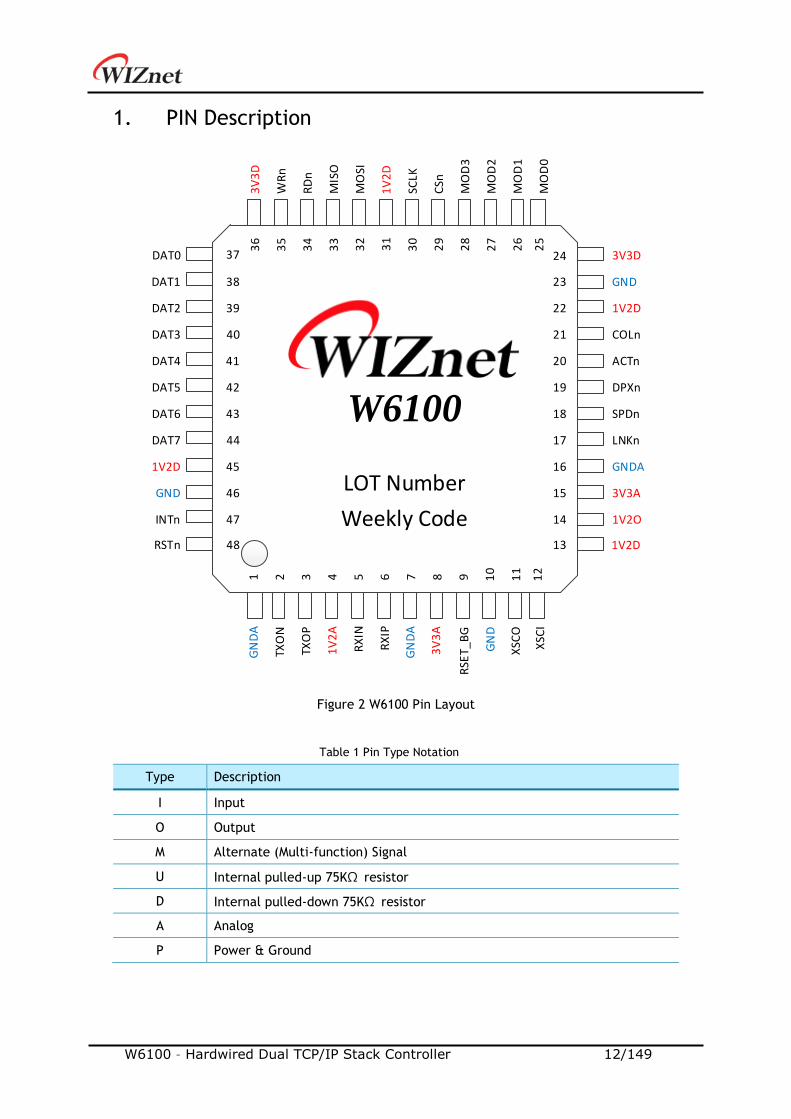
1. PIN Description
1 2 3 4 5 6 7 8 9 10
11
12
36
35
34
33
32
31
30
29
28
27
26
25
13
14
15
16
17
18
19
20
21
22
23
24
48
47
46
45
44
43
42
41
40
39
38
37
RSTn
INTn
GND
1V2D
DAT7
DAT6
DAT5
DAT4
DAT3
DAT2
DAT1
DAT0G
ND
A
TXO
N
TXO
P
1V
2A
RX
IN
RX
IP
RSE
T_B
G
3V
3A
XSC
O
XSC
I1V2D
GN
D
1V2O
3V3A
GNDA
LNKn
SPDn
DPXn
ACTn
COLn
1V2D
3V3D
WR
n
RD
n
MIS
O
MO
SI
1V
2D
SCLK
CSn
MO
D3
MO
D2
MO
D1
MO
D0
3V
3D
GN
DA
GND
W6100
LOT Number
Weekly Code
Figure 2 W6100 Pin Layout
Table 1 Pin Type Notation
Type Description
I Input
O Output
M Alternate (Multi-function) Signal
U Internal pulled-up 75KΩ resistor
D Internal pulled-down 75KΩ resistor
A Analog
P Power & Ground

W6100 – Hardwired Dual TCP/IP Stack Controller 13/149
1.1 PIN Description
Table 2 PIN Description
PIN # Symbol Type Description
1 GNDA AP Analog Ground
2 TXON AO Differential Transmitted Signal Pair
Data is transmitted to Media in TXOP/TXON differential
signal pair on MDI Mode. 3 TXOP AO
4 1V2A AP
Analog 1.2V Power
1V2O(PIN14) voltage source must be supplied back to this
pin.
5 RXIN AI Differential Received Signal Pair
Data is received from Media in RXIP/RXIN differential signal
pair on MDI Mode. 6 RXIP AI
7 GNDA AP Analog Ground
8 3V3A AP Analog 3.3V Power
9 RSET_BG AO
Off-chip Bias Resistor
Must be connected to Analog Ground through external
12.3KΩ, tolerance rate 1% Resistance.
10 GND AP Digital Ground
11 XSCO AO
25MHz Clock
Connect 25MHz Crystal Oscillator (XTAL) or Oscillator
(OSC) for internal operation clock (SYS_CLK).
W6100 can convert it to 25MHz or 100MHz and uses the
converted clock as SYS_CLK.
In normal mode, SYS_CLK is 100MHz.
In low frequency mode, SYS_CLK is 25MHz
* CAUTION If OSC is used, [email protected] must be used and only
XSCI must be connected and XSCO must be floated.
ref) “Clock Selection Guide” on http://wizwiki.net.
12
XSCI AI
13 1V2D P Digital 1.2V Power
1V2O voltage source must be supplied to this pin.
14 1V2O PO
Internal Regulator 1.2V Power Output
Power which Internal Regulator of W6100 supplies. It
supports Max 150mA.
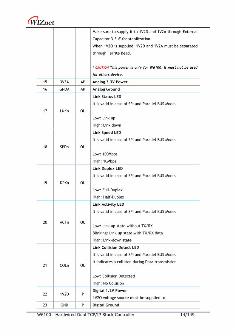
W6100 – Hardwired Dual TCP/IP Stack Controller 14/149
Make sure to supply it to 1V2D and 1V2A through External
Capacitor 3.3uF for stabilization.
When 1V2O is supplied, 1V2D and 1V2A must be separated
through Ferrite Bead.
* CAUTION This power is only for W6100. It must not be used
for others device.
15 3V3A AP Analog 3.3V Power
16 GNDA AP Analog Ground
17 LNKn OU
Link Status LED
It is valid in case of SPI and Parallel BUS Mode.
Low: Link up
High: Link down
18 SPDn OU
Link Speed LED
It is valid in case of SPI and Parallel BUS Mode.
Low: 100Mbps
High: 10Mbps
19 DPXn OU
Link Duplex LED
It is valid in case of SPI and Parallel BUS Mode.
Low: Full-Duplex
High: Half-Duplex
20 ACTn OU
Link Activity LED
It is valid in case of SPI and Parallel BUS Mode.
Low: Link up state without TX/RX
Blinking: Link up state with TX/RX data
High: Link-down state
21 COLn OU
Link Collision Detect LED
It is valid in case of SPI and Parallel BUS Mode.
It indicates a collision during Data transmission.
Low: Collision Detected
High: No Collision
22 1V2D P Digital 1.2V Power
1V2O voltage source must be supplied to.
23 GND P Digital Ground
W6100 – Hardwired Dual TCP/IP Stack Controller 15/149
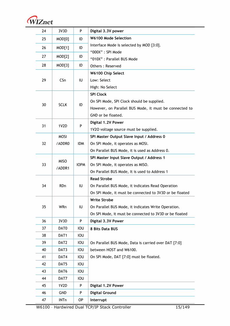
24 3V3D P Digital 3.3V power
25 MOD[0] ID W6100 Mode Selection
Interface Mode is selected by MOD [3:0].
“000X” : SPI Mode
“010X” : Parallel BUS Mode
Others : Reserved
26 MOD[1] ID
27 MOD[2] ID
28 MOD[3] ID
29 CSn IU
W6100 Chip Select
Low: Select
High: No Select
30 SCLK ID
SPI Clock
On SPI Mode, SPI Clock should be supplied.
However, on Parallel BUS Mode, it must be connected to
GND or be floated.
31 1V2D P Digital 1.2V Power
1V2O voltage source must be supplied.
32
MOSI
/ADDR0
IDM
SPI Master Output Slave Input / Address 0
On SPI Mode, it operates as MOSI.
On Parallel BUS Mode, it is used as Address 0.
33 MISO
/ADDR1 IOPM
SPI Master Input Slave Output / Address 1
On SPI Mode, it operates as MISO.
On Parallel BUS Mode, It is used to Address 1
34 RDn IU
Read Strobe
On Parallel BUS Mode, it indicates Read Operation
On SPI Mode, it must be connected to 3V3D or be floated
35 WRn IU
Write Strobe
On Parallel BUS Mode, it indicates Write Operation.
On SPI Mode, it must be connected to 3V3D or be floated
36 3V3D P Digital 3.3V Power
37 DAT0 IOU 8 Bits Data BUS
On Parallel BUS Mode, Data is carried over DAT [7:0]
between HOST and W6100.
On SPI Mode, DAT [7:0] must be floated.
38 DAT1 IOU
39 DAT2 IOU
40 DAT3 IOU
41 DAT4 IOU
42 DAT5 IOU
43 DAT6 IOU
44 DAT7 IOU
45 1V2D P Digital 1.2V Power
46 GND P Digital Ground
47 INTn OP Interrupt
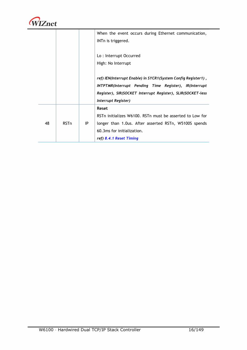
W6100 – Hardwired Dual TCP/IP Stack Controller 16/149
When the event occurs during Ethernet communication,
INTn is triggered.
Lo : Interrupt Occurred
High: No Interrupt
ref) IEN(Interrupt Enable) in SYCR1(System Config Register1) ,
INTPTMR(Interrupt Pending Time Register), IR(Interrupt
Register), SIR(SOCKET Interrupt Register), SLIR(SOCKET-less
Interrupt Register)
48 RSTn IP
Reset
RSTn initializes W6100. RSTn must be asserted to Low for
longer than 1.0us. After asserted RSTn, W5100S spends
60.3ms for initialization.
ref) 8.4.1 Reset Timing
W6100 – Hardwired Dual TCP/IP Stack Controller 17/149
2. Memory Map
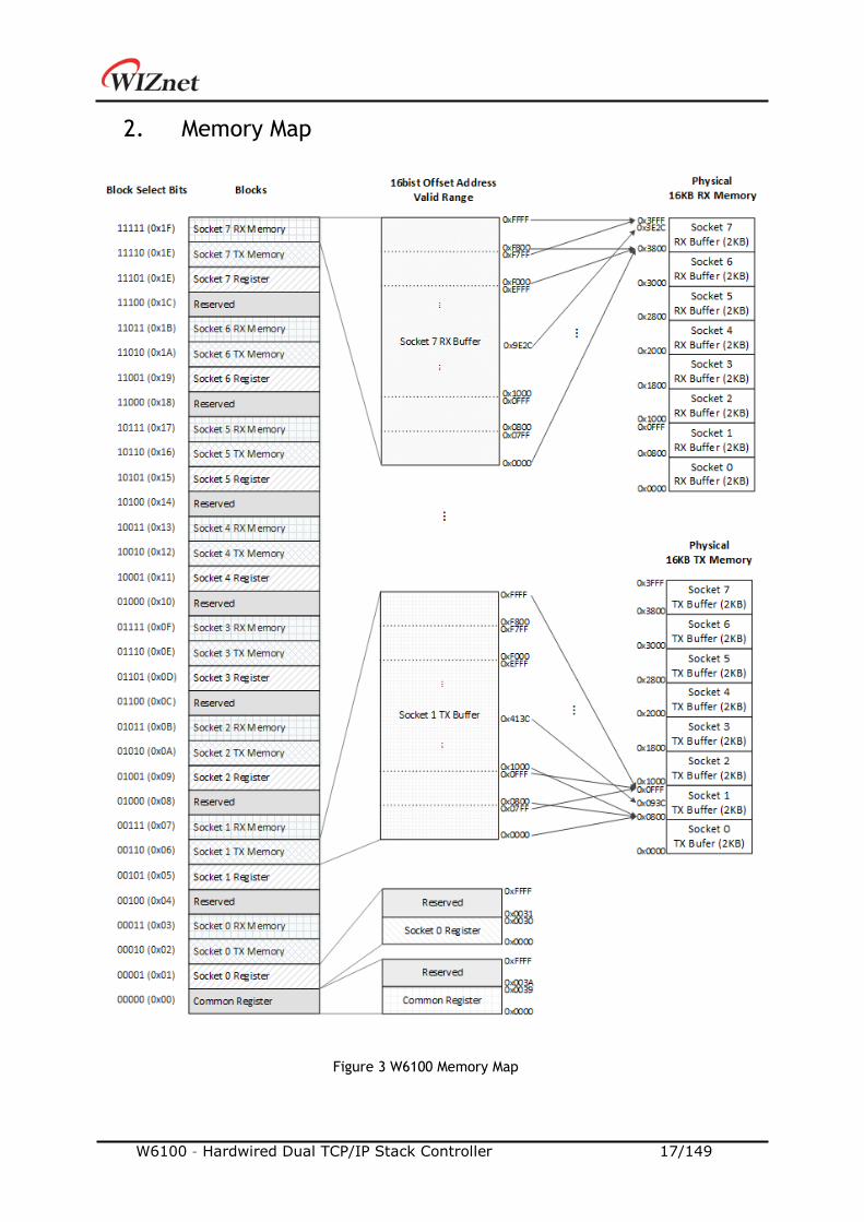
Figure 3 W6100 Memory Map
W6100 – Hardwired Dual TCP/IP Stack Controller 18/149
In Figure 3, W6100 consists the below blocks.
- 1 x Common Register Block, 7 x Reserved Block
- 8 x SOCKET n Register Block
- 8 x SOCKET n TX Buffer Block
- 8 x SOCKET n RX Buffer Block
These blocks are classified by block select 5bits. Each block is accessed with 16 bits offset
address.
SOCKET n TX Buffer Blocks (0≤n≤7) are initially allocated to 2KB each in 16KB TX memory. And
each Block can be reallocated to 0, 1, 2, 4, 8, or 16KB through Sn_TX_BSR(4.2.23). The total
allocated size of SOCKET n TX Buffer Blocks must not exceed 16KB.
SOCKET n RX Buffer Blocks (0≤n≤7) are also initially allocated to 2KB each in 16KB RX memory.
And each SOCKET n RX Buffer Block is reallocated in 0, 1, 2, 4, 8 or 16KB through
Sn_RX_BSR(4.2.27). The total Size of allocated SOCKET n RX Buffer Block must not exceed 16KB.
W6100 – Hardwired Dual TCP/IP Stack Controller 19/149
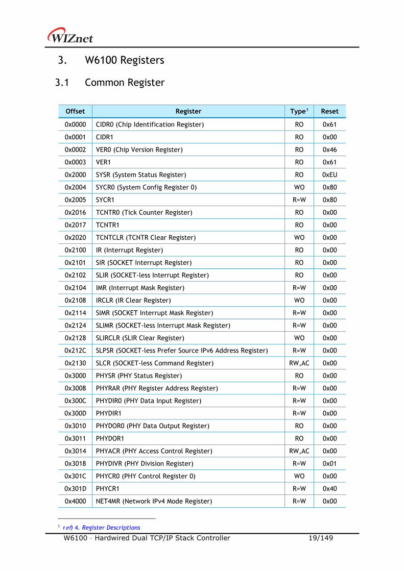
3. W6100 Registers
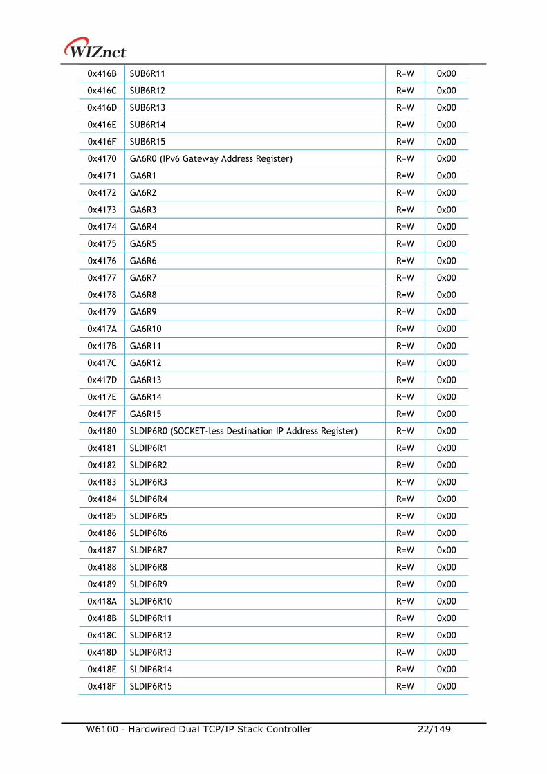
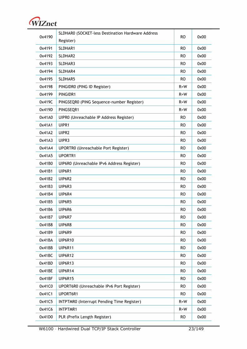
3.1 Common Register
Offset Register Type1 Reset
0x0000 CIDR0 (Chip Identification Register) RO 0x61
0x0001 CIDR1 RO 0x00
0x0002 VER0 (Chip Version Register) RO 0x46
0x0003 VER1 RO 0x61
0x2000 SYSR (System Status Register) RO 0xEU
0x2004 SYCR0 (System Config Register 0) WO 0x80
0x2005 SYCR1 R=W 0x80
0x2016 TCNTR0 (Tick Counter Register) RO 0x00
0x2017 TCNTR1 RO 0x00
0x2020 TCNTCLR (TCNTR Clear Register) WO 0x00
0x2100 IR (Interrupt Register) RO 0x00
0x2101 SIR (SOCKET Interrupt Register) RO 0x00
0x2102 SLIR (SOCKET-less Interrupt Register) RO 0x00
0x2104 IMR (Interrupt Mask Register) R=W 0x00
0x2108 IRCLR (IR Clear Register) WO 0x00
0x2114 SIMR (SOCKET Interrupt Mask Register) R=W 0x00
0x2124 SLIMR (SOCKET-less Interrupt Mask Register) R=W 0x00
0x2128 SLIRCLR (SLIR Clear Register) WO 0x00
0x212C SLPSR (SOCKET-less Prefer Source IPv6 Address Register) R=W 0x00
0x2130 SLCR (SOCKET-less Command Register) RW,AC 0x00
0x3000 PHYSR (PHY Status Register) RO 0x00
0x3008 PHYRAR (PHY Register Address Register) R=W 0x00
0x300C PHYDIR0 (PHY Data Input Register) R=W 0x00
0x300D PHYDIR1 R=W 0x00
0x3010 PHYDOR0 (PHY Data Output Register) RO 0x00
0x3011 PHYDOR1 RO 0x00
0x3014 PHYACR (PHY Access Control Register) RW,AC 0x00
0x3018 PHYDIVR (PHY Division Register) R=W 0x01
0x301C PHYCR0 (PHY Control Register 0) WO 0x00
0x301D PHYCR1 R=W 0x40
0x4000 NET4MR (Network IPv4 Mode Register) R=W 0x00
1 ref) 4. Register Descriptions
W6100 – Hardwired Dual TCP/IP Stack Controller 20/149
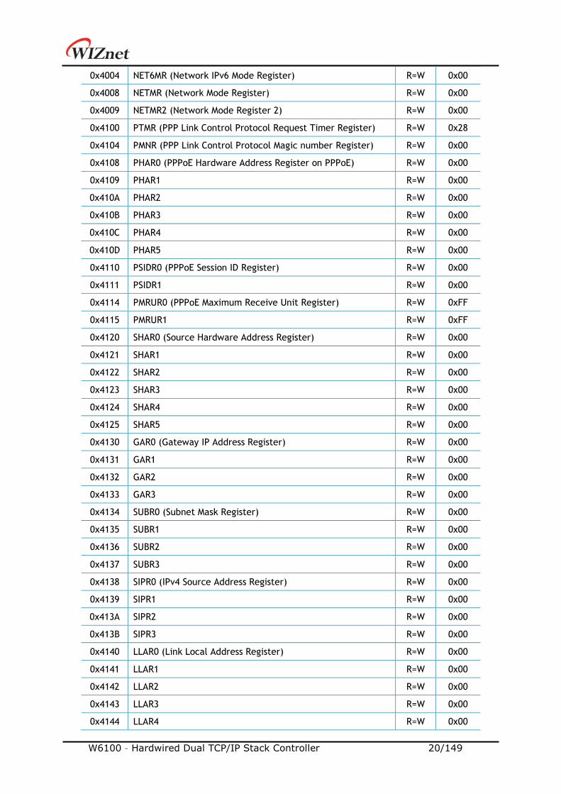
0x4004 NET6MR (Network IPv6 Mode Register) R=W 0x00
0x4008 NETMR (Network Mode Register) R=W 0x00
0x4009 NETMR2 (Network Mode Register 2) R=W 0x00
0x4100 PTMR (PPP Link Control Protocol Request Timer Register) R=W 0x28
0x4104 PMNR (PPP Link Control Protocol Magic number Register) R=W 0x00
0x4108 PHAR0 (PPPoE Hardware Address Register on PPPoE) R=W 0x00
0x4109 PHAR1 R=W 0x00
0x410A PHAR2 R=W 0x00
0x410B PHAR3 R=W 0x00
0x410C PHAR4 R=W 0x00
0x410D PHAR5 R=W 0x00
0x4110 PSIDR0 (PPPoE Session ID Register) R=W 0x00
0x4111 PSIDR1 R=W 0x00
0x4114 PMRUR0 (PPPoE Maximum Receive Unit Register) R=W 0xFF
0x4115 PMRUR1 R=W 0xFF
0x4120 SHAR0 (Source Hardware Address Register) R=W 0x00
0x4121 SHAR1 R=W 0x00
0x4122 SHAR2 R=W 0x00
0x4123 SHAR3 R=W 0x00
0x4124 SHAR4 R=W 0x00
0x4125 SHAR5 R=W 0x00
0x4130 GAR0 (Gateway IP Address Register) R=W 0x00
0x4131 GAR1 R=W 0x00
0x4132 GAR2 R=W 0x00
0x4133 GAR3 R=W 0x00
0x4134 SUBR0 (Subnet Mask Register) R=W 0x00
0x4135 SUBR1 R=W 0x00
0x4136 SUBR2 R=W 0x00
0x4137 SUBR3 R=W 0x00
0x4138 SIPR0 (IPv4 Source Address Register) R=W 0x00
0x4139 SIPR1 R=W 0x00
0x413A SIPR2 R=W 0x00
0x413B SIPR3 R=W 0x00
0x4140 LLAR0 (Link Local Address Register) R=W 0x00
0x4141 LLAR1 R=W 0x00
0x4142 LLAR2 R=W 0x00
0x4143 LLAR3 R=W 0x00
0x4144 LLAR4 R=W 0x00
W6100 – Hardwired Dual TCP/IP Stack Controller 21/149
0x4145 LLAR5 R=W 0x00
0x4146 LLAR6 R=W 0x00
0x4147 LLAR7 R=W 0x00
0x4148 LLAR8 R=W 0x00
0x4149 LLAR9 R=W 0x00
0x414A LLAR10 R=W 0x00
0x414B LLAR11 R=W 0x00
0x414C LLAR12 R=W 0x00
0x414D LLAR13 R=W 0x00
0x414E LLAR14 R=W 0x00
0x414F LLAR15 R=W 0x00
0x4150 GUAR0 (Global Unicast Address Register) R=W 0x00
0x4151 GUAR1 R=W 0x00
0x4152 GUAR2 R=W 0x00
0x4153 GUAR3 R=W 0x00
0x4154 GUAR4 R=W 0x00
0x4155 GUAR5 R=W 0x00
0x4156 GUAR6 R=W 0x00
0x4157 GUAR7 R=W 0x00
0x4158 GUAR8 R=W 0x00
0x4159 GUAR9 R=W 0x00
0x415A GUAR10 R=W 0x00
0x415B GUAR11 R=W 0x00
0x415C GUAR12 R=W 0x00
0x415D GUAR13 R=W 0x00
0x415E GUAR14 R=W 0x00
0x415F GUAR15 R=W 0x00
0x4160 SUB6R0 (IPv6 Subnet Prefix Register) R=W 0x00
0x4161 SUB6R1 R=W 0x00
0x4162 SUB6R2 R=W 0x00
0x4163 SUB6R3 R=W 0x00
0x4164 SUB6R4 R=W 0x00
0x4165 SUB6R5 R=W 0x00
0x4166 SUB6R6 R=W 0x00
0x4167 SUB6R7 R=W 0x00
0x4168 SUB6R8 R=W 0x00
0x4169 SUB6R9 R=W 0x00
0x416A SUB6R10 R=W 0x00
W6100 – Hardwired Dual TCP/IP Stack Controller 22/149
0x416B SUB6R11 R=W 0x00
0x416C SUB6R12 R=W 0x00
0x416D SUB6R13 R=W 0x00
0x416E SUB6R14 R=W 0x00
0x416F SUB6R15 R=W 0x00
0x4170 GA6R0 (IPv6 Gateway Address Register) R=W 0x00
0x4171 GA6R1 R=W 0x00
0x4172 GA6R2 R=W 0x00
0x4173 GA6R3 R=W 0x00
0x4174 GA6R4 R=W 0x00
0x4175 GA6R5 R=W 0x00
0x4176 GA6R6 R=W 0x00
0x4177 GA6R7 R=W 0x00
0x4178 GA6R8 R=W 0x00
0x4179 GA6R9 R=W 0x00
0x417A GA6R10 R=W 0x00
0x417B GA6R11 R=W 0x00
0x417C GA6R12 R=W 0x00
0x417D GA6R13 R=W 0x00
0x417E GA6R14 R=W 0x00
0x417F GA6R15 R=W 0x00
0x4180 SLDIP6R0 (SOCKET-less Destination IP Address Register) R=W 0x00
0x4181 SLDIP6R1 R=W 0x00
0x4182 SLDIP6R2 R=W 0x00
0x4183 SLDIP6R3 R=W 0x00
0x4184 SLDIP6R4 R=W 0x00
0x4185 SLDIP6R5 R=W 0x00
0x4186 SLDIP6R6 R=W 0x00
0x4187 SLDIP6R7 R=W 0x00
0x4188 SLDIP6R8 R=W 0x00
0x4189 SLDIP6R9 R=W 0x00
0x418A SLDIP6R10 R=W 0x00
0x418B SLDIP6R11 R=W 0x00
0x418C SLDIP6R12 R=W 0x00
0x418D SLDIP6R13 R=W 0x00
0x418E SLDIP6R14 R=W 0x00
0x418F SLDIP6R15 R=W 0x00
W6100 – Hardwired Dual TCP/IP Stack Controller 23/149
0x4190 SLDHAR0 (SOCKET-less Destination Hardware Address
Register) RO 0x00
0x4191 SLDHAR1 RO 0x00
0x4192 SLDHAR2 RO 0x00
0x4193 SLDHAR3 RO 0x00
0x4194 SLDHAR4 RO 0x00
0x4195 SLDHAR5 RO 0x00
0x4198 PINGIDR0 (PING ID Register) R=W 0x00
0x4199 PINGIDR1 R=W 0x00
0x419C PINGSEQR0 (PING Sequence-number Register) R=W 0x00
0x419D PINGSEQR1 R=W 0x00
0x41A0 UIPR0 (Unreachable IP Address Register) RO 0x00
0x41A1 UIPR1 RO 0x00
0x41A2 UIPR2 RO 0x00
0x41A3 UIPR3 RO 0x00
0x41A4 UPORTR0 (Unreachable Port Register) RO 0x00
0x41A5 UPORTR1 RO 0x00
0x41B0 UIP6R0 (Unreachable IPv6 Address Register) RO 0x00
0x41B1 UIP6R1 RO 0x00
0x41B2 UIP6R2 RO 0x00
0x41B3 UIP6R3 RO 0x00
0x41B4 UIP6R4 RO 0x00
0x41B5 UIP6R5 RO 0x00
0x41B6 UIP6R6 RO 0x00
0x41B7 UIP6R7 RO 0x00
0x41B8 UIP6R8 RO 0x00
0x41B9 UIP6R9 RO 0x00
0x41BA UIP6R10 RO 0x00
0x41BB UIP6R11 RO 0x00
0x41BC UIP6R12 RO 0x00
0x41BD UIP6R13 RO 0x00
0x41BE UIP6R14 RO 0x00
0x41BF UIP6R15 RO 0x00
0x41C0 UPORT6R0 (Unreachable IPv6 Port Register) RO 0x00
0x41C1 UPORT6R1 RO 0x00
0x41C5 INTPTMR0 (Interrupt Pending Time Register) R=W 0x00
0x41C6 INTPTMR1 R=W 0x00
0x41D0 PLR (Prefix Length Register) RO 0x00

W6100 – Hardwired Dual TCP/IP Stack Controller 24/149
0x41D4 PFR (Prefix Flag Register) RO 0x00
0x41D8 VLTR0 (Valid Life Time Register) RO 0x00
0x41D9 VLTR1 RO 0x00
0x41DA VLTR2 RO 0x00
0x41DB VLTR3 RO 0x00
0x41DC PLTR0 (Preferred Life Time Register) RO 0x00
0x41DD PLTR1 RO 0x00
0x41DE PLTR2 RO 0x00
0x41DF PLTR3 RO 0x00
0x41E0 PAR0 (Prefix Address Register) RO 0x00
0x41E1 PAR1 RO 0x00
0x41E2 PAR2 RO 0x00
0x41E3 PAR3 RO 0x00
0x41E4 PAR4 RO 0x00
0x41E5 PAR5 RO 0x00
0x41E6 PAR6 RO 0x00
0x41E7 PAR7 RO 0x00
0x41E8 PAR8 RO 0x00
0x41E9 PAR9 RO 0x00
0x41EA PAR10 RO 0x00
0x41EB PAR11 RO 0x00
0x41EC PAR12 RO 0x00
0x41ED PAR13 RO 0x00
0x41EE PAR14 RO 0x00
0x41EF PAR15 RO 0x00
0x41F0 ICMP6BLKR (ICMPv6 Block Register) R=W 0x00
0x41F4 CHPLCKR (Chip Lock Register) WO 0x00
0x41F5 NETLCKR (Network Lock Register) WO 0x00
0x41F6 PHYLCKR (PHY Lock Register) WO 0x00
0x4200 RTR0 (Retransmission Time Register) R=W 0x07
0x4201 RTR1 R=W 0xD0
0x4204 RCR (Retransmission Count Register) R=W 0x08
0x4208 SLRTR0 (SOCKET-less Retransmission Time Register) R=W 0x07
0x4209 SLRTR1 R=W 0xD0
0x420C SLRCR (SOCKET-less Retransmission Count Register) R=W 0x00
0x420F SLHOPR (Hop limit Register) R=W 0x80
W6100 – Hardwired Dual TCP/IP Stack Controller 25/149
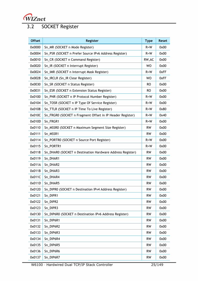
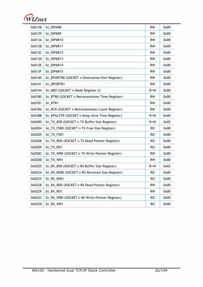
3.2 SOCKET Register
Offset Register Type Reset
0x0000 Sn_MR (SOCKET n Mode Register) R=W 0x00
0x0004 Sn_PSR (SOCKET n Prefer Source IPv6 Address Register) R=W 0x00
0x0010 Sn_CR (SOCKET n Command Register) RW,AC 0x00
0x0020 Sn_IR (SOCKET n Interrupt Register) WO 0x00
0x0024 Sn_IMR (SOCKET n Interrupt Mask Register) R=W 0xFF
0x0028 Sn_IRCLR (Sn_IR Clear Register) WO 0xFF
0x0030 Sn_SR (SOCKET n Status Register) RO 0x00
0x0031 Sn_ESR (SOCKET n Extension Status Register) RO 0x00
0x0100 Sn_PNR (SOCKET n IP Protocol Number Register) R=W 0x00
0x0104 Sn_TOSR (SOCKET n IP Type Of Service Register) R=W 0x00
0x0108 Sn_TTLR (SOCKET n IP Time To Live Register) R=W 0x80
0x010C Sn_FRGR0 (SOCKET n Fragment Offset in IP Header Register) R=W 0x40
0x010D Sn_FRGR1 R=W 0x00
0x0110 Sn_MSSR0 (SOCKET n Maximum Segment Size Register) RW 0x00
0x0111 Sn_MSSR1 RW 0x00
0x0114 Sn_PORTR0 (SOCKET n Source Port Register) R=W 0x00
0x0115 Sn_PORTR1 R=W 0x00
0x0118 Sn_DHAR0 (SOCKET n Destination Hardware Address Register) RW 0x00
0x0119 Sn_DHAR1 RW 0x00
0x011A Sn_DHAR2 RW 0x00
0x011B Sn_DHAR3 RW 0x00
0x011C Sn_DHAR4 RW 0x00
0x011D Sn_DHAR5 RW 0x00
0x0120 Sn_DIPR0 (SOCKET n Destination IPv4 Address Register) RW 0x00
0x0121 Sn_DIPR1 RW 0x00
0x0122 Sn_DIPR2 RW 0x00
0x0123 Sn_DIPR3 RW 0x00
0x0130 Sn_DIP6R0 (SOCKET n Destination IPv6 Address Register) RW 0x00
0x0131 Sn_DIP6R1 RW 0x00
0x0132 Sn_DIP6R2 RW 0x00
0x0133 Sn_DIP6R3 RW 0x00
0x0134 Sn_DIP6R4 RW 0x00
0x0135 Sn_DIP6R5 RW 0x00
0x0136 Sn_DIP6R6 RW 0x00
0x0137 Sn_DIP6R7 RW 0x00
W6100 – Hardwired Dual TCP/IP Stack Controller 26/149
0x0138 Sn_DIP6R8 RW 0x00
0x0139 Sn_DIP6R9 RW 0x00
0x013A Sn_DIP6R10 RW 0x00
0x013B Sn_DIP6R11 RW 0x00
0x013C Sn_DIP6R12 RW 0x00
0x013D Sn_DIP6R13 RW 0x00
0x013E Sn_DIP6R14 RW 0x00
0x013F Sn_DIP6R15 RW 0x00
0x0140 Sn_DPORTR0 (SOCKET n Destination Port Register) RW 0x00
0x0141 Sn_DPORTR1 RW 0x00
0x0144 Sn_MR2 (SOCKET n Mode Register 2) R=W 0x00
0x0180 Sn_RTR0 (SOCKET n Retransmission Time Register) RW 0x00
0x0181 Sn_RTR1 RW 0x00
0x0184 Sn_RCR (SOCKET n Retransmission Count Register) RW 0x00
0x0188 Sn_KPALVTR (SOCKET n Keep Alive Time Register) R=W 0x00
0x0200 Sn_TX_BSR (SOCKET n TX Buffer Size Register) R=W 0x02
0x0204 Sn_TX_FSR0 (SOCKET n TX Free Size Register) RO 0x00
0x0205 Sn_TX_FSR1 RO 0x00
0x0208 Sn_TX_RD0 (SOCKET n TX Read Pointer Register) RO 0x00
0x0209 Sn_TX_RD1 RO 0x00
0x020C Sn_TX_WR0 (SOCKET n TX Write Pointer Register) RW 0x00
0x020D Sn_TX_WR1 RW 0x00
0x0220 Sn_RX_BSR (SOCKET n RX Buffer Size Register) R=W 0x02
0x0224 Sn_RX_RSR0 (SOCKET n RX Received Size Register) RO 0x00
0x0225 Sn_RX_RSR1 RO 0x00
0x0228 Sn_RX_RD0 (SOCKET n RX Read Pointer Register) RW 0x00
0x0229 Sn_RX_RD1 RW 0x00
0x022C Sn_RX_WR0 (SOCKET n RX Write Pointer Register) RO 0x00
0x022D Sn_RX_WR1 RO 0x00
W6100 – Hardwired Dual TCP/IP Stack Controller 27/149
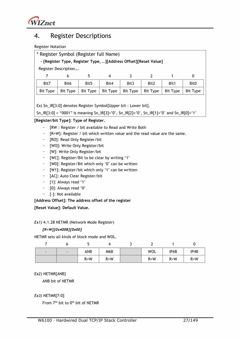
4. Register Descriptions
Register Notation
* Register Symbol (Register full Name)
- [Register Type, Register Type, …][Address Offset][Reset Value]
Register Description….
7 6 5 4 3 2 1 0
Bit7 Bit6 Bit5 Bit4 Bit3 Bit2 Bit1 Bit0
Bit Type Bit Type Bit Type Bit Type Bit Type Bit Type Bit Type Bit Type
Ex) Sn_IR[3:0] denotes Register Symbol[Upper bit : Lower bit].
Sn_IR[3:0] = “0001” is meaning Sn_IR[3]=’0’, Sn_IR[2]=’0’, Sn_IR[1]=’0’ and Sn_IR[0]=’1’
[Register/bit Type]: Type of Register.
- [RW : Register / bit available to Read and Write Both
- [R=W]: Register / bit which written value and the read value are the same.
- [RO]: Read Only Register/bit
- [WO]: Write Only Register/bit
- [W]: Write Only Register/bit
- [WC]: Register/Bit to be clear by writing ‘1’
- [W0]: Register/Bit which only ‘0’ can be written
- [W1]: Register/bit which only ‘1’ can be written
- [AC]: Auto Clear Register/bit
- [1]: Always read ‘1’
- [0]: Always read ‘0’
- [-]: Not available
[Address Offset]: The address offset of the register
[Reset Value]: Default Value.
Ex1) 4.1.28 NETMR (Network Mode Register)
[R=W][0x4008][0x00]
NETMR sets all kinds of block mode and WOL.
7 6 5 4 3 2 1 0
- - ANB M6B WOL IP6B IP4B
R=W R=W R=W R=W R=W
Ex2) NETMR[ANB]
ANB bit of NETMR
Ex3) NETMR[7:0]
From 7th bit to 0th bit of NETMR
W6100 – Hardwired Dual TCP/IP Stack Controller 28/149
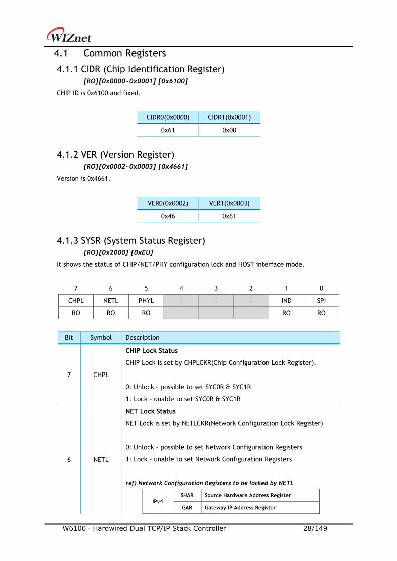
4.1 Common Registers
4.1.1 CIDR (Chip Identification Register)
[RO][0x0000~0x0001] [0x6100]
CHIP ID is 0x6100 and fixed.
CIDR0(0x0000) CIDR1(0x0001)
0x61 0x00
4.1.2 VER (Version Register)
[RO][0x0002~0x0003] [0x4661]
Version is 0x4661.
VER0(0x0002) VER1(0x0003)
0x46 0x61
4.1.3 SYSR (System Status Register)
[RO][0x2000] [0xEU]
It shows the status of CHIP/NET/PHY configuration lock and HOST interface mode.
7 6 5 4 3 2 1 0
CHPL NETL PHYL - - - IND SPI
RO RO RO RO RO
Bit Symbol Description
7 CHPL
CHIP Lock Status
CHIP Lock is set by CHPLCKR(Chip Configuration Lock Register).
0: Unlock – possible to set SYC0R & SYC1R
1: Lock – unable to set SYC0R & SYC1R
6 NETL
NET Lock Status
NET Lock is set by NETLCKR(Network Configuration Lock Register)
0: Unlock – possible to set Network Configuration Registers
1: Lock – unable to set Network Configuration Registers
ref) Network Configuration Registers to be locked by NETL
IPv4 SHAR Source Hardware Address Register
GAR Gateway IP Address Register
W6100 – Hardwired Dual TCP/IP Stack Controller 29/149
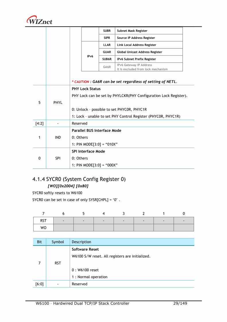
SUBR Subnet Mask Register
SIPR Source IP Address Register
IPv6
LLAR Link Local Address Register
GUAR Global Unicast Address Register
SUB6R IPv6 Subnet Prefix Register
GA6R IPv6 Gateway IP Address
It is excluded from lock mechanism
* CAUTION : GA6R can be set regardless of setting of NETL.
5 PHYL
PHY Lock Status
PHY Lock can be set by PHYLCKR(PHY Configuration Lock Register).
0: Unlock – possible to set PHYC0R, PHYC1R
1: Lock – unable to set PHY Control Register (PHYC0R, PHYC1R)
[4:2] - Reserved
1 IND
Parallel BUS Interface Mode
0: Others
1: PIN MODE[3:0] = “010X”
0 SPI
SPI Interface Mode
0: Others
1: PIN MODE[3:0] = “000X”
4.1.4 SYCR0 (System Config Register 0)
[WO][0x2004] [0x80]
SYCR0 softly resets to W6100
SYCR0 can be set in case of only SYSR[CHPL] = ‘0’ .
7 6 5 4 3 2 1 0
RST - - - - - - -
WO
Bit Symbol Description
7 RST
Software Reset
W6100 S/W reset. All registers are initialized.
0 : W6100 reset
1 : Normal operation
[6:0] - Reserved
W6100 – Hardwired Dual TCP/IP Stack Controller 30/149
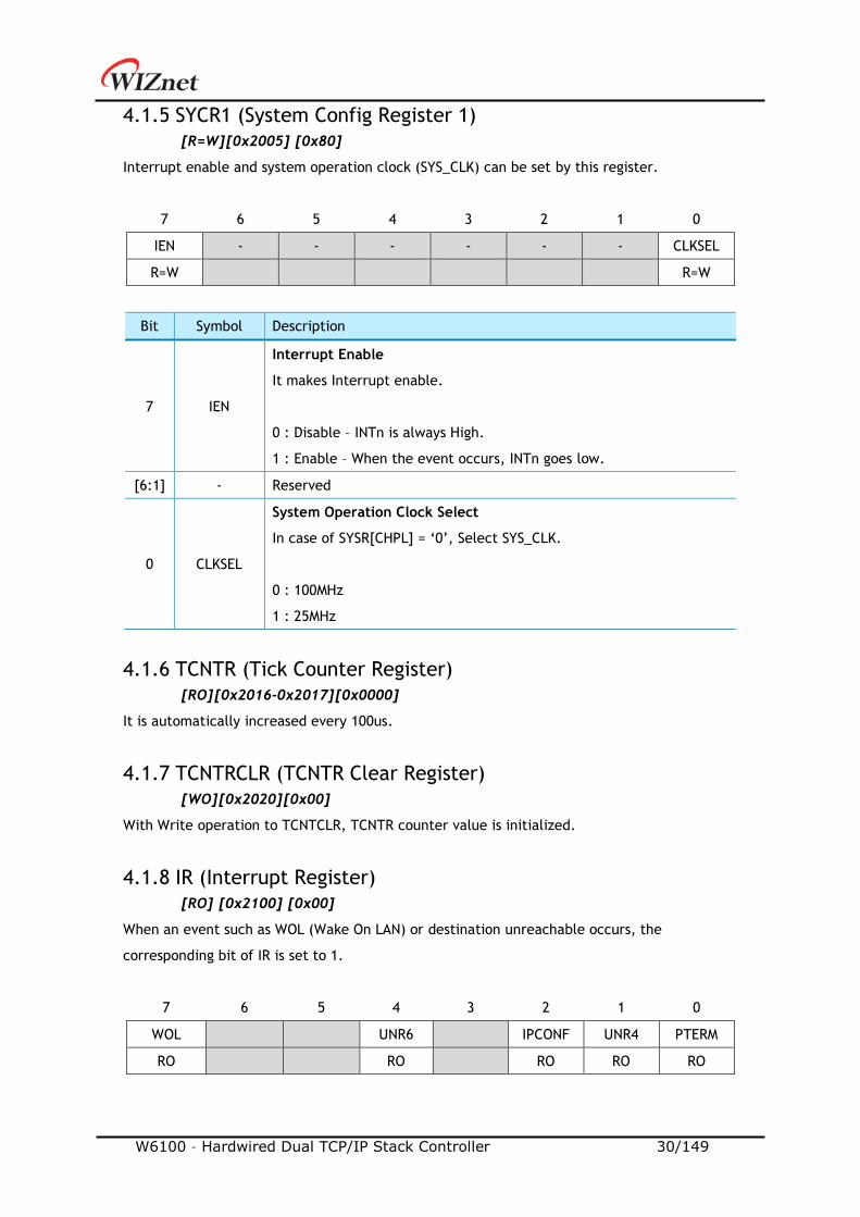
4.1.5 SYCR1 (System Config Register 1)
[R=W][0x2005] [0x80]
Interrupt enable and system operation clock (SYS_CLK) can be set by this register.
7 6 5 4 3 2 1 0
IEN - - - - - - CLKSEL
R=W R=W
Bit Symbol Description
7 IEN
Interrupt Enable
It makes Interrupt enable.
0 : Disable – INTn is always High.
1 : Enable – When the event occurs, INTn goes low.
[6:1] - Reserved
0 CLKSEL
System Operation Clock Select
In case of SYSR[CHPL] = ‘0’, Select SYS_CLK.
0 : 100MHz
1 : 25MHz
4.1.6 TCNTR (Tick Counter Register)
[RO][0x2016-0x2017][0x0000]
It is automatically increased every 100us.
4.1.7 TCNTRCLR (TCNTR Clear Register)
[WO][0x2020][0x00]
With Write operation to TCNTCLR, TCNTR counter value is initialized.
4.1.8 IR (Interrupt Register)
[RO] [0x2100] [0x00]
When an event such as WOL (Wake On LAN) or destination unreachable occurs, the
corresponding bit of IR is set to 1.
7 6 5 4 3 2 1 0
WOL UNR6 IPCONF UNR4 PTERM
RO RO RO RO RO

W6100 – Hardwired Dual TCP/IP Stack Controller 31/149
Bit Symbol Description
7 WOL
WOL(Wake On LAN) Magic Packet
0 : Others
1 : WOL MAGIC Packet received
[6:5] - Reserved
4 UNR6
Destination IPv6 Port Unreachable
0 : Others
1 : ICMPv6 Destination Port Unreachable Packet received
ref) The Unreachable IPv6 Address and the Port Number of the received
Unreachable Packet are stored in UIP6R (Unreachable IPv6 Address
Register) and UPORT6R (Unreachable IPv6 Port Register), respectively.
3 - Reserved
2 IPCONF
IP Conflict
0 : Others
1 : IPv4 Address Conflict occurred
1 UNR4
Destination Port Unreachable
0: Others
1: ICMPv4 Destination Port Unreachable Packet received
ref) The Unreachable IP Address and Port Number of the received
Unreachable Packet are stored in UIPR (Unreachable IP Address
Register) and UPORTR (Unreachable Port Register), respectively.
0 PTERM
PPPoE Terminated
0 : Others
1 : a PPPoE connection was terminated by receving PPPT or LCPT
packets
4.1.9 SIR (SOCKET Interrupt Register)
[RO] [0x2101] [0x00]
When the IR of a specific SOCKET is not ‘0’, corresponding bit is set to ‘1’.
7 6 5 4 3 2 1 0
S7_INT S6_INT S5_INT S4_INT S3_INT S2_INT S1_INT S0_INT
RO RO RO RO RO RO RO RO
Bit Symbol Description
[7:0] Sn_INT- SOCKET n Interrupt

W6100 – Hardwired Dual TCP/IP Stack Controller 32/149
0 : when Sn_IR is ‘0’
1 : when Sn_IR is not ‘0’
4.1.10 SLIR (SOCKET-less Interrupt Register)
[RO] [0x2102] [0x00]
When a specific command of the SLCR (SOCKET-less Command Register) is successfully
executed, timeout occurs for the executed command, or an ICMPv6 RA packet is received
from the IPv6 Gateway (Router), the corresponding bit is set.
7 6 5 4 3 2 1 0
TOUT ARP4 PING4 ARP6 PING6 NS RS RA
RO RO RO RO RO RO RO RO
Bit Symbol Description
7 TOUT
Timeout Interrupt
0 : Others
1 : When TIMEOUT occurs after any SOCKET-less Command
6 ARP4
ARP Interrupt
0 : Others
1 : When ARP Reply received after SOCKET-less ARP command
5 PING4
PING Interrupt
0 : Others
1 : When PING Reply received after SOCKET-less PING command
4 ARP6
IPv6 ARP Interrupt
0 : Others
1 : When ARP6 Reply received after SOCKET-less ARP6 command
3 PING6
IPv6 PING Interrupt
0 : Others
1 : When PING6 Reply received after SOCKET-less PING6 command
2 NS
DAD NS Interrupt
0 : Others
1 : When NA received after SOCKET-less NS command
ref) NS bit is used for IPv6 Address Confliction Detection.
1 RS
Auto configuration RS Interrupt
0 : Others
1 : When RA received after SOCKET-less RS command
0 RA
RA Receive Interrupt
0 : Others
1 : When All-node RA received from IPv6 Gateway
W6100 – Hardwired Dual TCP/IP Stack Controller 33/149
When SLIR [RS] = '1' or SLIR [RA] = '1', a prefix information of RA Packet is stored to corresponding
registers as follows and can be used for IPv6 Auto-configuration.
- PLR (Prefix Length Register)
- PFR (Prefix Flag Register)
- VLTR (RA Valid Life Time Register)
- PLTR (RA Preferred Life Time Register)
- PAR (Prefix Address Register)
* CAUTION: Only when the first option of received RA message is source link-layer
address(0x01) and the second option is prefix information Option (0x03), the above registers
are correct set. Otherwise, it can receive the RA message using the IPRAW6 Mode SOCKET
and process the prefix information.
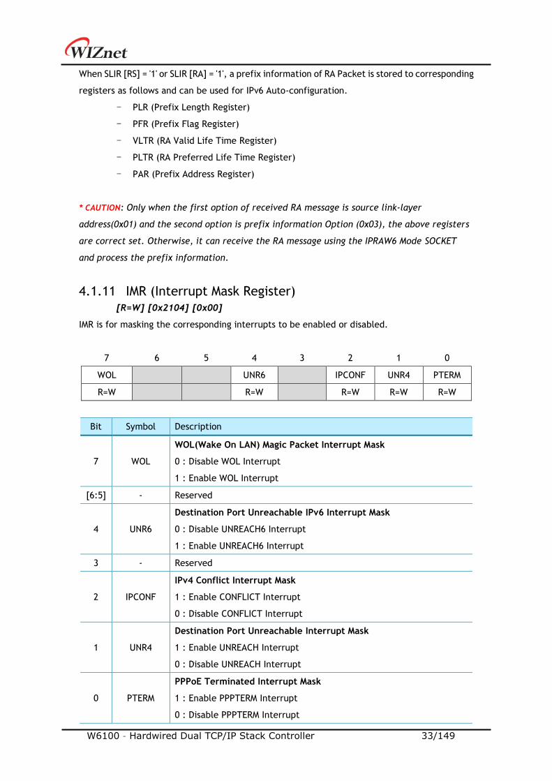
4.1.11 IMR (Interrupt Mask Register)
[R=W] [0x2104] [0x00]
IMR is for masking the corresponding interrupts to be enabled or disabled.
7 6 5 4 3 2 1 0
WOL UNR6 IPCONF UNR4 PTERM
R=W R=W R=W R=W R=W
Bit Symbol Description
7 WOL
WOL(Wake On LAN) Magic Packet Interrupt Mask
0 : Disable WOL Interrupt
1 : Enable WOL Interrupt
[6:5] - Reserved
4 UNR6
Destination Port Unreachable IPv6 Interrupt Mask
0 : Disable UNREACH6 Interrupt
1 : Enable UNREACH6 Interrupt
3 - Reserved
2 IPCONF
IPv4 Conflict Interrupt Mask
1 : Enable CONFLICT Interrupt
0 : Disable CONFLICT Interrupt
1 UNR4
Destination Port Unreachable Interrupt Mask
1 : Enable UNREACH Interrupt
0 : Disable UNREACH Interrupt
0 PTERM
PPPoE Terminated Interrupt Mask
1 : Enable PPPTERM Interrupt
0 : Disable PPPTERM Interrupt
W6100 – Hardwired Dual TCP/IP Stack Controller 34/149
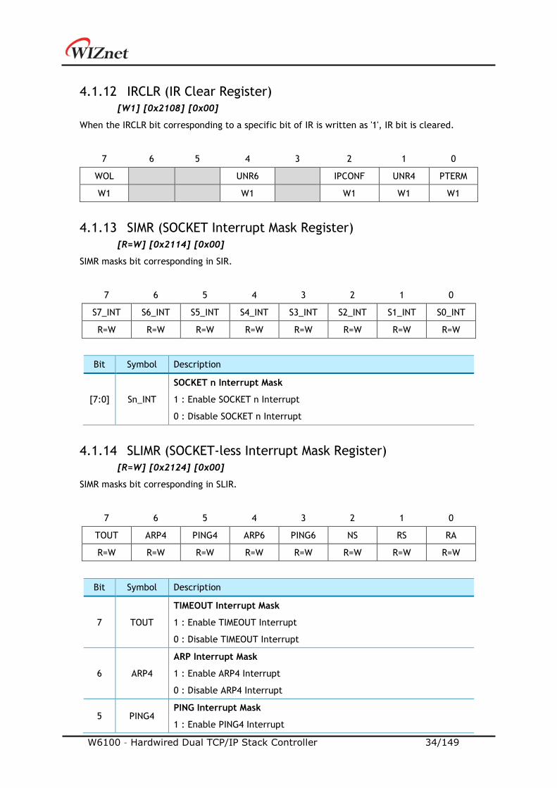
4.1.12 IRCLR (IR Clear Register)
[W1] [0x2108] [0x00]
When the IRCLR bit corresponding to a specific bit of IR is written as '1', IR bit is cleared.
7 6 5 4 3 2 1 0
WOL UNR6 IPCONF UNR4 PTERM
W1 W1 W1 W1 W1
4.1.13 SIMR (SOCKET Interrupt Mask Register)
[R=W] [0x2114] [0x00]
SIMR masks bit corresponding in SIR.
7 6 5 4 3 2 1 0
S7_INT S6_INT S5_INT S4_INT S3_INT S2_INT S1_INT S0_INT
R=W R=W R=W R=W R=W R=W R=W R=W
Bit Symbol Description
[7:0] Sn_INT
SOCKET n Interrupt Mask
1 : Enable SOCKET n Interrupt
0 : Disable SOCKET n Interrupt
4.1.14 SLIMR (SOCKET-less Interrupt Mask Register)
[R=W] [0x2124] [0x00]
SIMR masks bit corresponding in SLIR.
7 6 5 4 3 2 1 0
TOUT ARP4 PING4 ARP6 PING6 NS RS RA
R=W R=W R=W R=W R=W R=W R=W R=W
Bit Symbol Description
7 TOUT
TIMEOUT Interrupt Mask
1 : Enable TIMEOUT Interrupt
0 : Disable TIMEOUT Interrupt
6 ARP4
ARP Interrupt Mask
1 : Enable ARP4 Interrupt
0 : Disable ARP4 Interrupt
5 PING4 PING Interrupt Mask
1 : Enable PING4 Interrupt
W6100 – Hardwired Dual TCP/IP Stack Controller 35/149
0 : Disable PING4 Interrupt
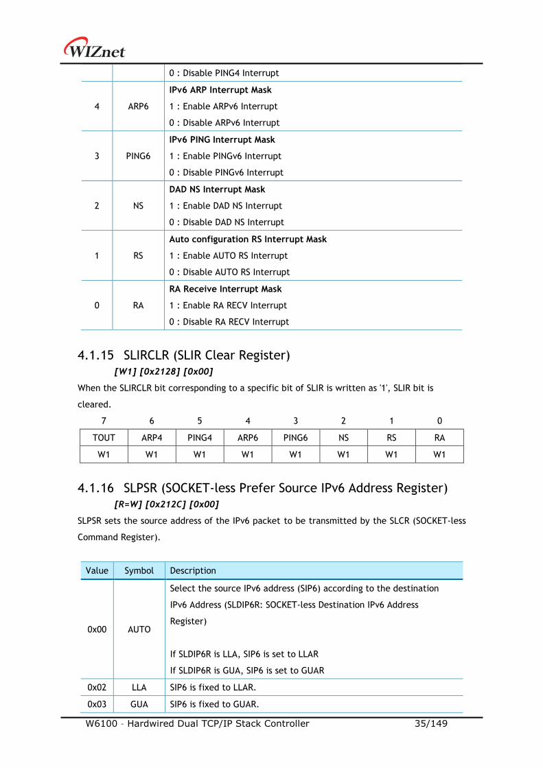
4 ARP6
IPv6 ARP Interrupt Mask
1 : Enable ARPv6 Interrupt
0 : Disable ARPv6 Interrupt
3 PING6
IPv6 PING Interrupt Mask
1 : Enable PINGv6 Interrupt
0 : Disable PINGv6 Interrupt
2 NS
DAD NS Interrupt Mask
1 : Enable DAD NS Interrupt
0 : Disable DAD NS Interrupt
1 RS
Auto configuration RS Interrupt Mask
1 : Enable AUTO RS Interrupt
0 : Disable AUTO RS Interrupt
0 RA
RA Receive Interrupt Mask
1 : Enable RA RECV Interrupt
0 : Disable RA RECV Interrupt
4.1.15 SLIRCLR (SLIR Clear Register)
[W1] [0x2128] [0x00]
When the SLIRCLR bit corresponding to a specific bit of SLIR is written as '1', SLIR bit is
cleared.
7 6 5 4 3 2 1 0
TOUT ARP4 PING4 ARP6 PING6 NS RS RA
W1 W1 W1 W1 W1 W1 W1 W1
4.1.16 SLPSR (SOCKET-less Prefer Source IPv6 Address Register)
[R=W] [0x212C] [0x00]
SLPSR sets the source address of the IPv6 packet to be transmitted by the SLCR (SOCKET-less
Command Register).
Value Symbol Description
0x00 AUTO
Select the source IPv6 address (SIP6) according to the destination
IPv6 Address (SLDIP6R: SOCKET-less Destination IPv6 Address
Register)
If SLDIP6R is LLA, SIP6 is set to LLAR
If SLDIP6R is GUA, SIP6 is set to GUAR
0x02 LLA SIP6 is fixed to LLAR.
0x03 GUA SIP6 is fixed to GUAR.

W6100 – Hardwired Dual TCP/IP Stack Controller 36/149
4.1.17 SLCR (SOCKET-less Command Register)
[RW, AC] [0x2130] [0x00]
SLCR performs a command to transmit a specific packet without SOCKET. Command is cleared
automatically after completion, and it cannot execute another command before the previous
command is cleared. The result of the command execution is confirmed by SLIR (SOCKET-less
Interrupt Register).
7 6 5 4 3 2 1 0
- ARP4 PING4 ARP6 PING6 NS RS UNA
RW RW RW RW RW RW RW
Bit Symbol Description
7 - Reserved
6 ARP4
ARP Request Transmission Command
1 : Transmit ARP Request.
0 : Ready
5 PING4
IPv4 PING Request Transmission Command
1 : Transmit PING Request.
0 : Ready
4 ARP6
NS ARP Transmission Command
1 : Transmit NS ARP.
0 : Ready
3 PING6
IPv6 PING Request Transmission Command
1 : Transmit IPv6 PING Request.
0 : Ready
2 NS
NS Transmission Command for DAD
1 : Transmit NS packet for DAD.
0 : Ready
1 RS
Auto configuration RS Transmission Command
1 : Transmit RS packet.
0 : Ready
0 UNA
Unsolicited NA Transmission Command
1 : Transmit Unsolicited NA packet.
0 : Ready

W6100 – Hardwired Dual TCP/IP Stack Controller 37/149
4.1.18 PHYSR (PHY Status Register)
[RO] [0x3000] [0x00]
PHYSR checks PHY operation mode and LINK status set through PHYCR0(PHY Control Register
0).
7 6 5 4 3 2 1 0
CAB - MODE2 MODE1 MODE0 DPX SPD LNK
RO RO RO RO RO RO RO
Bit Symbol Description
7 CAB
Cable OFF bit
1 : Cable Unplugged
0 : Cable Plugged
6 - Reserved
[5:3] MODE
[2:0]
PHY OPMODE
MODE2 MODE1 MODE0 Description
0 X X Auto Negotiation
1 0 0 100BASE-TX FDX
1 0 1 100BASE-TX HDX
1 1 0 10BASE-T FDX
1 1 1 10BASE-T HDX
2 DPX
Flag Duplex bit (When Link Up)
1 : Half Duplex
0 : Full Duplex
1 SPD
Flag Speed bit (When Link Up)
1 : 10Mbps
0 : 100Mbps
0 LNK
Flag Link bit
1 : Link Up
0 : Link Down
4.1.19 PHYRAR (PHY Register Address Register)
[R=W] [0x3008] [0x00]
PHYRAR sets PHY register address in integrated Ethernet PHY.
7 6 5 4 3 2 1 0
- - - A4 A3 A2 A1 A0
R=W R=W R=W R=W R=W
W6100 – Hardwired Dual TCP/IP Stack Controller 38/149
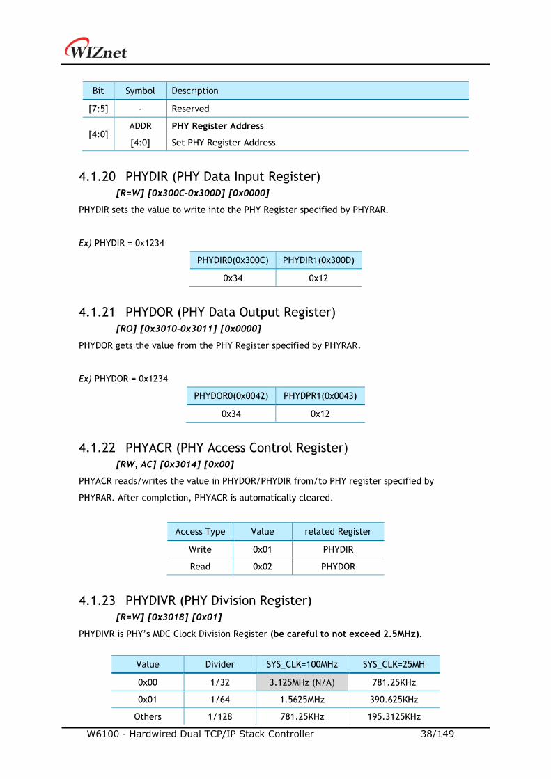
Bit Symbol Description
[7:5] - Reserved
[4:0] ADDR
[4:0]
PHY Register Address
Set PHY Register Address
4.1.20 PHYDIR (PHY Data Input Register)
[R=W] [0x300C-0x300D] [0x0000]
PHYDIR sets the value to write into the PHY Register specified by PHYRAR.
Ex) PHYDIR = 0x1234
PHYDIR0(0x300C) PHYDIR1(0x300D)
0x34 0x12
4.1.21 PHYDOR (PHY Data Output Register)
[RO] [0x3010-0x3011] [0x0000]
PHYDOR gets the value from the PHY Register specified by PHYRAR.
Ex) PHYDOR = 0x1234
PHYDOR0(0x0042) PHYDPR1(0x0043)
0x34 0x12
4.1.22 PHYACR (PHY Access Control Register)
[RW, AC] [0x3014] [0x00]
PHYACR reads/writes the value in PHYDOR/PHYDIR from/to PHY register specified by
PHYRAR. After completion, PHYACR is automatically cleared.
Access Type Value related Register
Write 0x01 PHYDIR
Read 0x02 PHYDOR
4.1.23 PHYDIVR (PHY Division Register)
[R=W] [0x3018] [0x01]
PHYDIVR is PHY’s MDC Clock Division Register (be careful to not exceed 2.5MHz).
Value Divider SYS_CLK=100MHz SYS_CLK=25MH
0x00 1/32 3.125MHz (N/A) 781.25KHz
0x01 1/64 1.5625MHz 390.625KHz
Others 1/128 781.25KHz 195.3125KHz
W6100 – Hardwired Dual TCP/IP Stack Controller 39/149
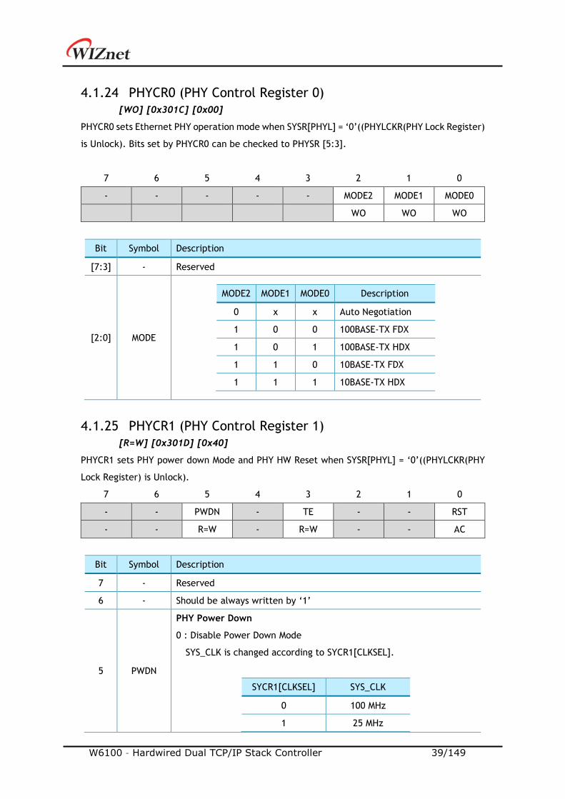
4.1.24 PHYCR0 (PHY Control Register 0)
[WO] [0x301C] [0x00]
PHYCR0 sets Ethernet PHY operation mode when SYSR[PHYL] = ‘0’((PHYLCKR(PHY Lock Register)
is Unlock). Bits set by PHYCR0 can be checked to PHYSR [5:3].
7 6 5 4 3 2 1 0
- - - - - MODE2 MODE1 MODE0
WO WO WO
Bit Symbol Description
[7:3] - Reserved
[2:0] MODE
MODE2 MODE1 MODE0 Description
0 x x Auto Negotiation
1 0 0 100BASE-TX FDX
1 0 1 100BASE-TX HDX
1 1 0 10BASE-TX FDX
1 1 1 10BASE-TX HDX
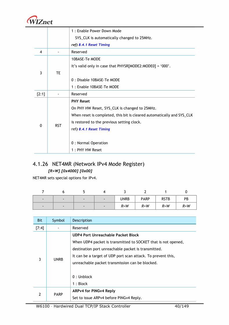
4.1.25 PHYCR1 (PHY Control Register 1)
[R=W] [0x301D] [0x40]
PHYCR1 sets PHY power down Mode and PHY HW Reset when SYSR[PHYL] = ‘0’((PHYLCKR(PHY
Lock Register) is Unlock).
7 6 5 4 3 2 1 0
- - PWDN - TE - - RST
- - R=W - R=W - - AC
Bit Symbol Description
7 - Reserved
6 - Should be always written by ‘1’
5 PWDN
PHY Power Down
0 : Disable Power Down Mode
SYS_CLK is changed according to SYCR1[CLKSEL].
SYCR1[CLKSEL] SYS_CLK
0 100 MHz
1 25 MHz
W6100 – Hardwired Dual TCP/IP Stack Controller 40/149
1 : Enable Power Down Mode
SYS_CLK is automatically changed to 25MHz.
ref) 8.4.1 Reset Timing
4 - Reserved
3 TE
10BASE-Te MODE
It’s valid only in case that PHYSR[MODE2:MODE0] = ‘000’.
0 : Disable 10BASE-Te MODE
1 : Enable 10BASE-Te MODE
[2:1] - Reserved
0 RST
PHY Reset
On PHY HW Reset, SYS_CLK is changed to 25MHz.
When reset is completed, this bit is cleared automatically and SYS_CLK
is restored to the previous setting clock.
ref) 8.4.1 Reset Timing
0 : Normal Operation
1 : PHY HW Reset
4.1.26 NET4MR (Network IPv4 Mode Register)
[R=W] [0x4000] [0x00]
NET4MR sets special options for IPv4.
7 6 5 4 3 2 1 0
- - - - UNRB PARP RSTB PB
- - - - R=W R=W R=W R=W
Bit Symbol Description
[7:4] - Reserved
3 UNRB
UDP4 Port Unreachable Packet Block
When UDP4 packet is transmitted to SOCKET that is not opened,
destination port unreachable packet is transmitted.
It can be a target of UDP port scan attack. To prevent this,
unreachable packet transmission can be blocked.
0 : Unblock
1 : Block
2 PARP ARPv4 for PINGv4 Reply
Set to issue ARPv4 before PINGv4 Reply.
W6100 – Hardwired Dual TCP/IP Stack Controller 41/149
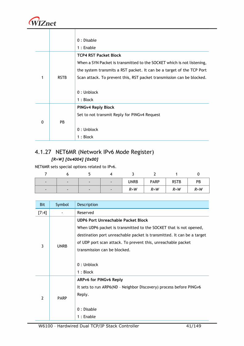
0 : Disable
1 : Enable
1 RSTB
TCP4 RST Packet Block
When a SYN Packet is transmitted to the SOCKET which is not listening,
the system transmits a RST packet. It can be a target of the TCP Port
Scan attack. To prevent this, RST packet transmission can be blocked.
0 : Unblock
1 : Block
0 PB
PINGv4 Reply Block
Set to not transmit Reply for PINGv4 Request
0 : Unblock
1 : Block
4.1.27 NET6MR (Network IPv6 Mode Register)
[R=W] [0x4004] [0x00]
NET6MR sets special options related to IPv6.
7 6 5 4 3 2 1 0
- - - - UNRB PARP RSTB PB
- - - - R=W R=W R=W R=W
Bit Symbol Description
[7:4] - Reserved
3 UNRB
UDP6 Port Unreachable Packet Block
When UDP6 packet is transmitted to the SOCKET that is not opened,
destination port unreachable packet is transmitted. It can be a target
of UDP port scan attack. To prevent this, unreachable packet
transmission can be blocked.
0 : Unblock
1 : Block
2 PARP
ARPv6 for PINGv6 Reply
It sets to run ARP6(ND – Neighbor Discovery) process before PINGv6
Reply.
0 : Disable
1 : Enable
W6100 – Hardwired Dual TCP/IP Stack Controller 42/149
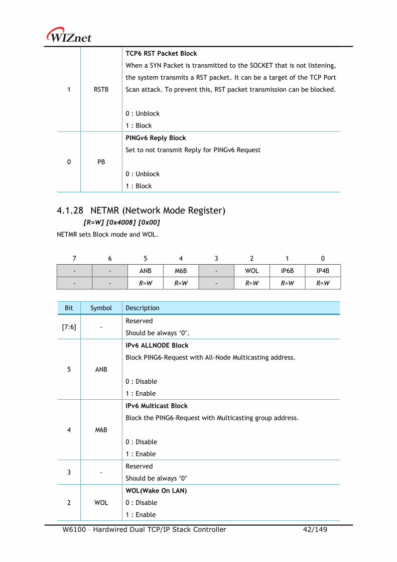
1 RSTB
TCP6 RST Packet Block
When a SYN Packet is transmitted to the SOCKET that is not listening,
the system transmits a RST packet. It can be a target of the TCP Port
Scan attack. To prevent this, RST packet transmission can be blocked.
0 : Unblock
1 : Block
0 PB
PINGv6 Reply Block
Set to not transmit Reply for PINGv6 Request
0 : Unblock
1 : Block
4.1.28 NETMR (Network Mode Register)
[R=W] [0x4008] [0x00]
NETMR sets Block mode and WOL.
7 6 5 4 3 2 1 0
- - ANB M6B - WOL IP6B IP4B
- - R=W R=W - R=W R=W R=W
Bit Symbol Description
[7:6] - Reserved
Should be always ‘0’.
5 ANB
IPv6 ALLNODE Block
Block PING6-Request with All-Node Multicasting address.
0 : Disable
1 : Enable
4 M6B
IPv6 Multicast Block
Block the PING6-Request with Multicasting group address.
0 : Disable
1 : Enable
3 - Reserved
Should be always ‘0’
2 WOL
WOL(Wake On LAN)
0 : Disable
1 : Enable
W6100 – Hardwired Dual TCP/IP Stack Controller 43/149
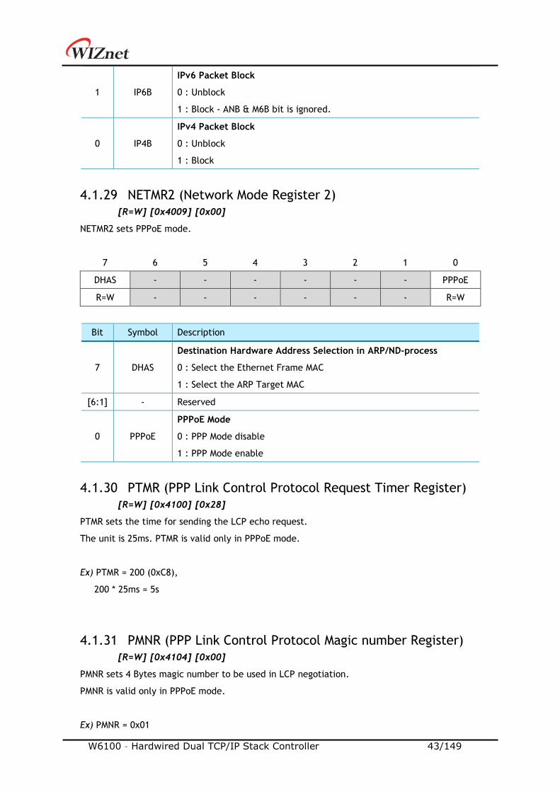
1 IP6B
IPv6 Packet Block
0 : Unblock
1 : Block - ANB & M6B bit is ignored.
0 IP4B
IPv4 Packet Block
0 : Unblock
1 : Block
4.1.29 NETMR2 (Network Mode Register 2)
[R=W] [0x4009] [0x00]
NETMR2 sets PPPoE mode.
7 6 5 4 3 2 1 0
DHAS - - - - - - PPPoE
R=W - - - - - - R=W
Bit Symbol Description
7 DHAS
Destination Hardware Address Selection in ARP/ND-process
0 : Select the Ethernet Frame MAC
1 : Select the ARP Target MAC
[6:1] - Reserved
0 PPPoE
PPPoE Mode
0 : PPP Mode disable
1 : PPP Mode enable
4.1.30 PTMR (PPP Link Control Protocol Request Timer Register)
[R=W] [0x4100] [0x28]
PTMR sets the time for sending the LCP echo request.
The unit is 25ms. PTMR is valid only in PPPoE mode.
Ex) PTMR = 200 (0xC8),
200 * 25ms = 5s
4.1.31 PMNR (PPP Link Control Protocol Magic number Register)
[R=W] [0x4104] [0x00]
PMNR sets 4 Bytes magic number to be used in LCP negotiation.
PMNR is valid only in PPPoE mode.
Ex) PMNR = 0x01
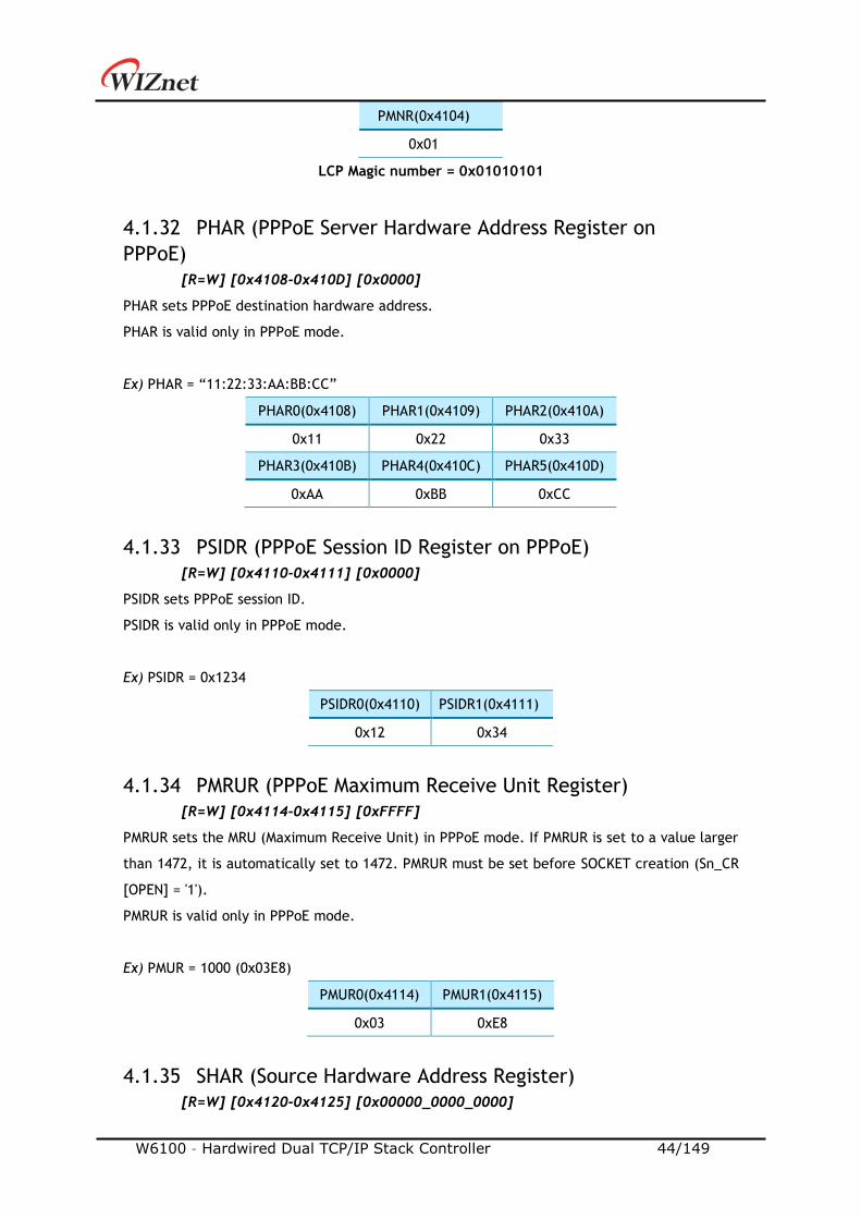
W6100 – Hardwired Dual TCP/IP Stack Controller 44/149
PMNR(0x4104)
0x01
LCP Magic number = 0x01010101
4.1.32 PHAR (PPPoE Server Hardware Address Register on
PPPoE)
[R=W] [0x4108-0x410D] [0x0000]
PHAR sets PPPoE destination hardware address.
PHAR is valid only in PPPoE mode.
Ex) PHAR = “11:22:33:AA:BB:CC”
PHAR0(0x4108) PHAR1(0x4109) PHAR2(0x410A)
0x11 0x22 0x33
PHAR3(0x410B) PHAR4(0x410C) PHAR5(0x410D)
0xAA 0xBB 0xCC
4.1.33 PSIDR (PPPoE Session ID Register on PPPoE)
[R=W] [0x4110-0x4111] [0x0000]
PSIDR sets PPPoE session ID.
PSIDR is valid only in PPPoE mode.
Ex) PSIDR = 0x1234
PSIDR0(0x4110) PSIDR1(0x4111)
0x12 0x34
4.1.34 PMRUR (PPPoE Maximum Receive Unit Register)
[R=W] [0x4114-0x4115] [0xFFFF]
PMRUR sets the MRU (Maximum Receive Unit) in PPPoE mode. If PMRUR is set to a value larger
than 1472, it is automatically set to 1472. PMRUR must be set before SOCKET creation (Sn_CR
[OPEN] = '1').
PMRUR is valid only in PPPoE mode.
Ex) PMUR = 1000 (0x03E8)
PMUR0(0x4114) PMUR1(0x4115)
0x03 0xE8
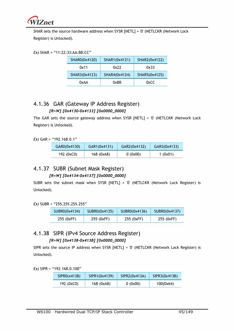
4.1.35 SHAR (Source Hardware Address Register)
[R=W] [0x4120-0x4125] [0x00000_0000_0000]
W6100 – Hardwired Dual TCP/IP Stack Controller 45/149
SHAR sets the source hardware address when SYSR [NETL] = '0' (NETLCKR (Network Lock
Register) is Unlocked).
Ex) SHAR = “11:22:33:AA:BB:CC”
SHAR0(0x4120) SHAR1(0x4121) SHAR2(0x4122)
0x11 0x22 0x33
SHAR3(0x4123) SHAR4(0x4124) SHAR5(0x4125)
0xAA 0xBB 0xCC
4.1.36 GAR (Gateway IP Address Register)
[R=W] [0x4130-0x4133] [0x0000_0000]
The GAR sets the source gateway address when SYSR [NETL] = '0' (NETLCKR (Network Lock
Register) is Unlocked).
Ex) GAR = “192.168.0.1”
GAR0(0x4130) GAR1(0x4131) GAR2(0x4132) GAR3(0x4133)
192 (0xC0) 168 (0xA8) 0 (0x00) 1 (0x01)
4.1.37 SUBR (Subnet Mask Register)
[R=W] [0x4134–0x4137] [0x0000_0000]
SUBR sets the subnet mask when SYSR [NETL] = '0' (NETLCKR (Network Lock Register) is
Unlocked).
Ex) SUBR = “255.255.255.255”
SUBR0(0x4134) SUBR0(0x4135) SUBR0(0x4136) SUBR0(0x4137)
255 (0xFF) 255 (0xFF) 255 (0xFF) 255 (0xFF)
4.1.38 SIPR (IPv4 Source Address Register)
[R=W] [0x4138-0x413B] [0x0000_0000]
SIPR sets the source IP address when SYSR [NETL] = '0' (NETLCKR (Network Lock Register) is
Unlocked).
Ex) SIPR = “192.168.0.100”
SIPR0(x4138) SIPR1(0x4139) SIPR2(0x413A) SIPR3(0x413B)
192 (0xC0) 168 (0xA8) 0 (0x00) 100(0x64)
W6100 – Hardwired Dual TCP/IP Stack Controller 46/149
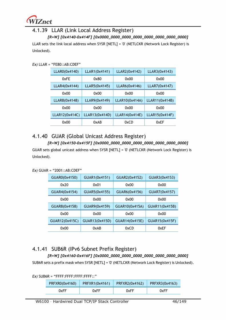
4.1.39 LLAR (Link Local Address Register)
[R=W] [0x4140-0x414F] [0x0000_0000_0000_0000_0000_0000_0000_0000]
LLAR sets the link local address when SYSR [NETL] = '0' (NETLCKR (Network Lock Register) is
Unlocked).
Ex) LLAR = “FE80::AB:CDEF”
LLAR0(0x4140) LLAR1(0x4141) LLAR2(0x4142) LLAR3(0x4143)
0xFE 0x80 0x00 0x00
LLAR4(0x4144) LLAR5(0x4145) LLAR6(0x4146) LLAR7(0x4147)
0x00 0x00 0x00 0x00
LLAR8(0x4148) LLAR9(0x4149) LLAR10(0x414A) LLAR11(0x414B)
0x00 0x00 0x00 0x00
LLAR12(0x414C) LLAR13(0x414D) LLAR14(0x414E) LLAR15(0x414F)
0x00 0xAB 0xCD 0xEF
4.1.40 GUAR (Global Unicast Address Register)
[R=W] [0x4150-0x415F] [0x0000_0000_0000_0000_0000_0000_0000_0000]
GUAR sets global unicast address when SYSR [NETL] = '0' (NETLCKR (Network Lock Register) is
Unlocked).
Ex) GUAR = “2001::AB:CDEF”
GUAR0(0x4150) GUAR1(0x4151) GUAR2(0x4152) GUAR3(0x4153)
0x20 0x01 0x00 0x00
GUAR4(0x4154) GUAR5(0x4155) GUAR6(0x4156) GUAR7(0x4157)
0x00 0x00 0x00 0x00
GUAR8(0x4158) GUAR9(0x4159) GUAR10(0x415A) GUAR11(0x415B)
0x00 0x00 0x00 0x00
GUAR12(0x415C) GUAR13(0x415D) GUAR14(0x415E) GUAR15(0x415F)
0x00 0xAB 0xCD 0xEF
4.1.41 SUB6R (IPv6 Subnet Prefix Register)
[R=W] [0x4160-0x416F] [0x0000_0000_0000_0000_0000_0000_0000_0000]
SUB6R sets a prefix mask when SYSR [NETL] = '0' (NETLCKR (Network Lock Register) is Unlocked).
Ex) SUB6R = “FFFF:FFFF:FFFF:FFFF::”
PRFXR0(0x4160) PRFXR1(0x4161) PRFXR2(0x4162) PRFXR3(0x4163)
0xFF 0xFF 0xFF 0xFF
W6100 – Hardwired Dual TCP/IP Stack Controller 47/149
PRFXR4(0x4164) PRFXR5(0x4165) PRFXR6(0x4166) PRFXR7(0x4167)
0xFF 0xFF 0xFF 0xFF
PRFXR8(0x4168) PRFXR9(0x4169) PRFXR10(0x416A) PRFXR11(0x416B)
0x00 0x00 0x00 0x00
PRFXR12(0x416C) PRFXR13(0x416D) PRFXR14(0x416E) PRFXR15(0x416F)
0x00 0x00 0x00 0x00
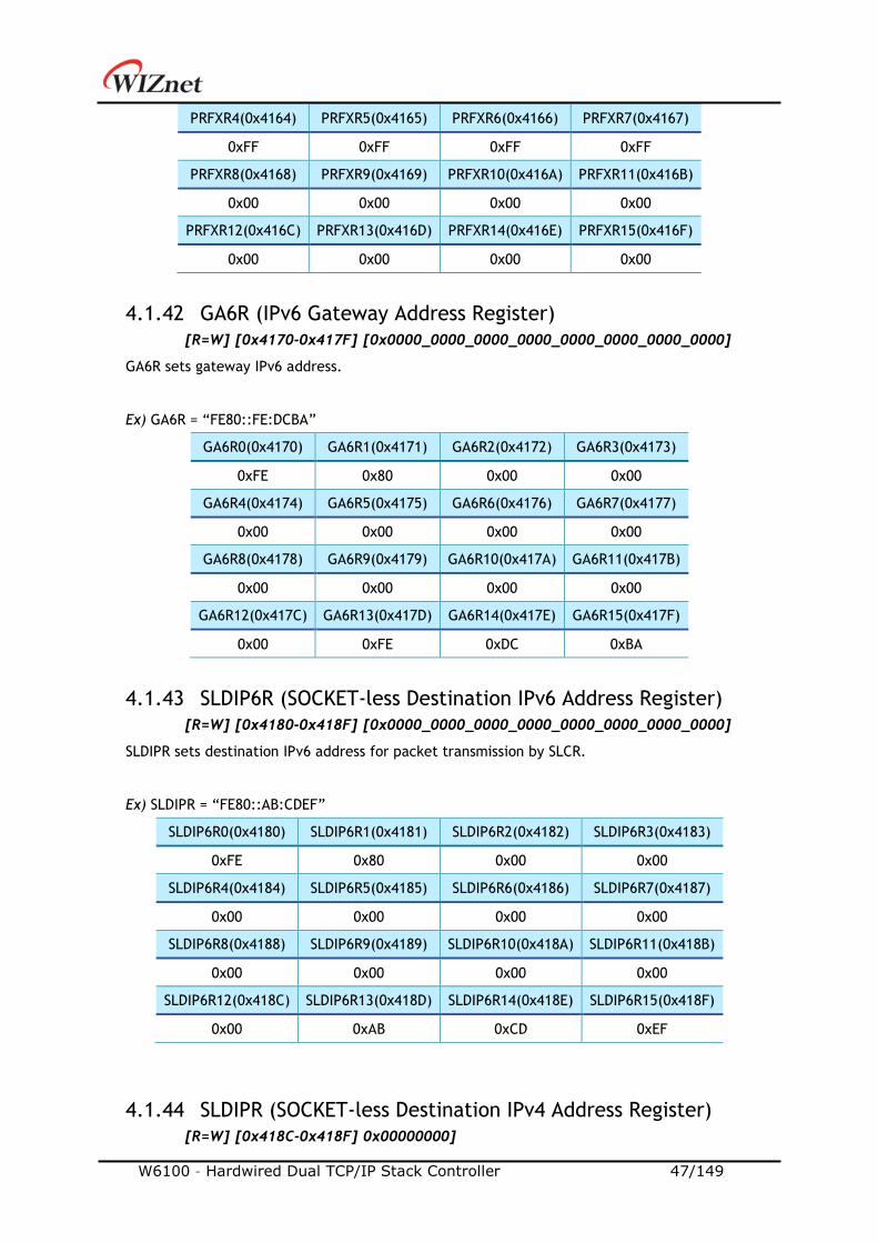
4.1.42 GA6R (IPv6 Gateway Address Register)
[R=W] [0x4170-0x417F] [0x0000_0000_0000_0000_0000_0000_0000_0000]
GA6R sets gateway IPv6 address.
Ex) GA6R = “FE80::FE:DCBA”
GA6R0(0x4170) GA6R1(0x4171) GA6R2(0x4172) GA6R3(0x4173)
0xFE 0x80 0x00 0x00
GA6R4(0x4174) GA6R5(0x4175) GA6R6(0x4176) GA6R7(0x4177)
0x00 0x00 0x00 0x00
GA6R8(0x4178) GA6R9(0x4179) GA6R10(0x417A) GA6R11(0x417B)
0x00 0x00 0x00 0x00
GA6R12(0x417C) GA6R13(0x417D) GA6R14(0x417E) GA6R15(0x417F)
0x00 0xFE 0xDC 0xBA
4.1.43 SLDIP6R (SOCKET-less Destination IPv6 Address Register)
[R=W] [0x4180-0x418F] [0x0000_0000_0000_0000_0000_0000_0000_0000]
SLDIPR sets destination IPv6 address for packet transmission by SLCR.
Ex) SLDIPR = “FE80::AB:CDEF”
SLDIP6R0(0x4180) SLDIP6R1(0x4181) SLDIP6R2(0x4182) SLDIP6R3(0x4183)
0xFE 0x80 0x00 0x00
SLDIP6R4(0x4184) SLDIP6R5(0x4185) SLDIP6R6(0x4186) SLDIP6R7(0x4187)
0x00 0x00 0x00 0x00
SLDIP6R8(0x4188) SLDIP6R9(0x4189) SLDIP6R10(0x418A) SLDIP6R11(0x418B)
0x00 0x00 0x00 0x00
SLDIP6R12(0x418C) SLDIP6R13(0x418D) SLDIP6R14(0x418E) SLDIP6R15(0x418F)
0x00 0xAB 0xCD 0xEF
4.1.44 SLDIPR (SOCKET-less Destination IPv4 Address Register)
[R=W] [0x418C-0x418F] 0x00000000]
W6100 – Hardwired Dual TCP/IP Stack Controller 48/149
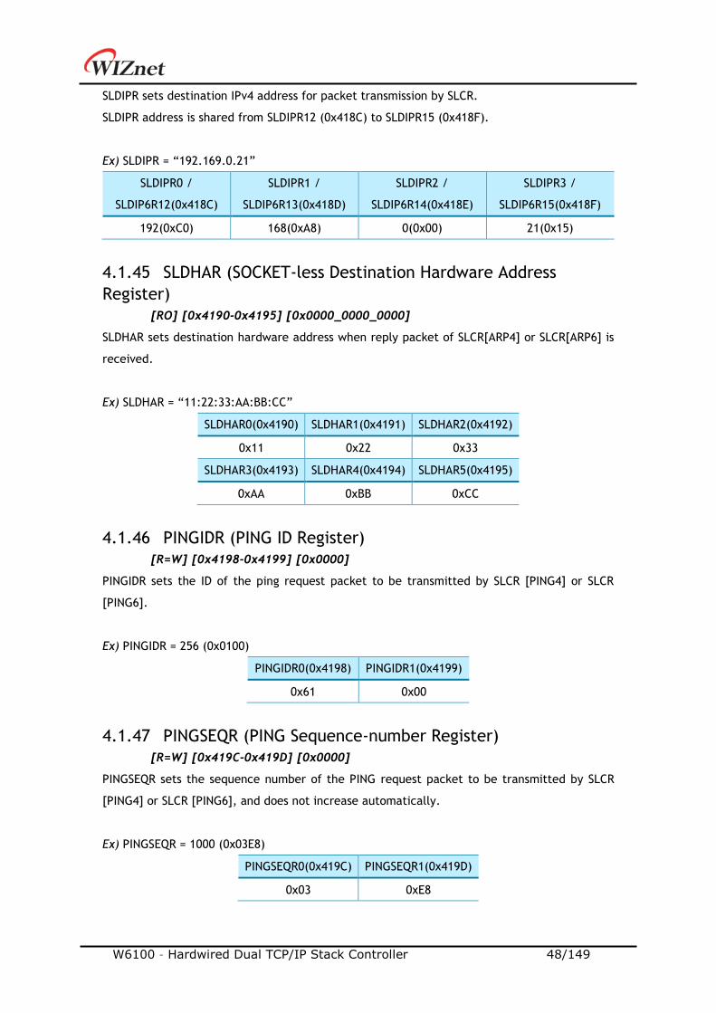
SLDIPR sets destination IPv4 address for packet transmission by SLCR.
SLDIPR address is shared from SLDIPR12 (0x418C) to SLDIPR15 (0x418F).
Ex) SLDIPR = “192.169.0.21”
SLDIPR0 /
SLDIP6R12(0x418C)
SLDIPR1 /
SLDIP6R13(0x418D)
SLDIPR2 /
SLDIP6R14(0x418E)
SLDIPR3 /
SLDIP6R15(0x418F)
192(0xC0) 168(0xA8) 0(0x00) 21(0x15)
4.1.45 SLDHAR (SOCKET-less Destination Hardware Address
Register)
[RO] [0x4190-0x4195] [0x0000_0000_0000]
SLDHAR sets destination hardware address when reply packet of SLCR[ARP4] or SLCR[ARP6] is
received.
Ex) SLDHAR = “11:22:33:AA:BB:CC”
SLDHAR0(0x4190) SLDHAR1(0x4191) SLDHAR2(0x4192)
0x11 0x22 0x33
SLDHAR3(0x4193) SLDHAR4(0x4194) SLDHAR5(0x4195)
0xAA 0xBB 0xCC
4.1.46 PINGIDR (PING ID Register)
[R=W] [0x4198-0x4199] [0x0000]
PINGIDR sets the ID of the ping request packet to be transmitted by SLCR [PING4] or SLCR
[PING6].
Ex) PINGIDR = 256 (0x0100)
PINGIDR0(0x4198) PINGIDR1(0x4199)
0x61 0x00
4.1.47 PINGSEQR (PING Sequence-number Register)
[R=W] [0x419C-0x419D] [0x0000]
PINGSEQR sets the sequence number of the PING request packet to be transmitted by SLCR
[PING4] or SLCR [PING6], and does not increase automatically.
Ex) PINGSEQR = 1000 (0x03E8)
PINGSEQR0(0x419C) PINGSEQR1(0x419D)
0x03 0xE8
W6100 – Hardwired Dual TCP/IP Stack Controller 49/149
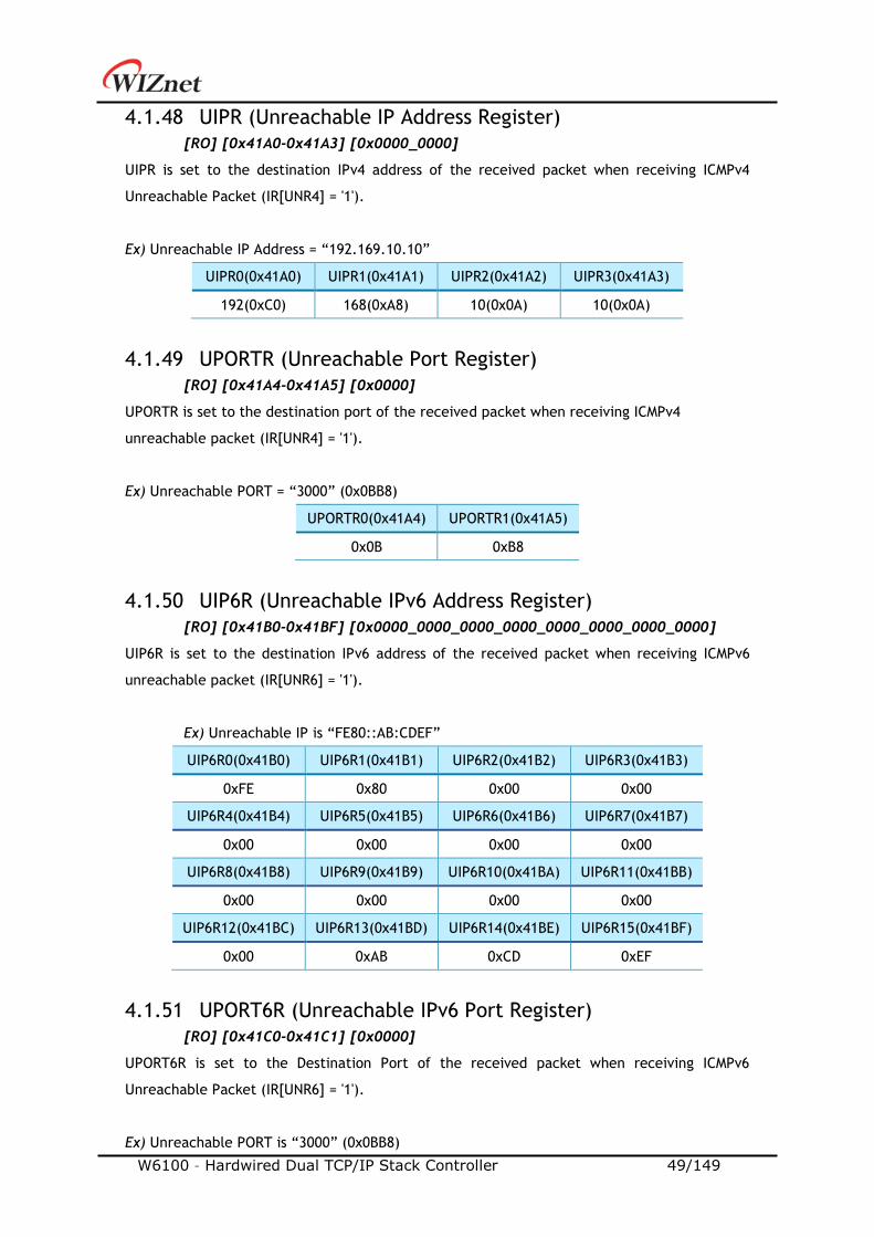
4.1.48 UIPR (Unreachable IP Address Register)
[RO] [0x41A0-0x41A3] [0x0000_0000]
UIPR is set to the destination IPv4 address of the received packet when receiving ICMPv4
Unreachable Packet (IR[UNR4] = '1').
Ex) Unreachable IP Address = “192.169.10.10”
UIPR0(0x41A0) UIPR1(0x41A1) UIPR2(0x41A2) UIPR3(0x41A3)
192(0xC0) 168(0xA8) 10(0x0A) 10(0x0A)
4.1.49 UPORTR (Unreachable Port Register)
[RO] [0x41A4-0x41A5] [0x0000]
UPORTR is set to the destination port of the received packet when receiving ICMPv4
unreachable packet (IR[UNR4] = '1').
Ex) Unreachable PORT = “3000” (0x0BB8)
UPORTR0(0x41A4) UPORTR1(0x41A5)
0x0B 0xB8
4.1.50 UIP6R (Unreachable IPv6 Address Register)
[RO] [0x41B0-0x41BF] [0x0000_0000_0000_0000_0000_0000_0000_0000]
UIP6R is set to the destination IPv6 address of the received packet when receiving ICMPv6
unreachable packet (IR[UNR6] = '1').
Ex) Unreachable IP is “FE80::AB:CDEF”
UIP6R0(0x41B0) UIP6R1(0x41B1) UIP6R2(0x41B2) UIP6R3(0x41B3)
0xFE 0x80 0x00 0x00
UIP6R4(0x41B4) UIP6R5(0x41B5) UIP6R6(0x41B6) UIP6R7(0x41B7)
0x00 0x00 0x00 0x00
UIP6R8(0x41B8) UIP6R9(0x41B9) UIP6R10(0x41BA) UIP6R11(0x41BB)
0x00 0x00 0x00 0x00
UIP6R12(0x41BC) UIP6R13(0x41BD) UIP6R14(0x41BE) UIP6R15(0x41BF)
0x00 0xAB 0xCD 0xEF
4.1.51 UPORT6R (Unreachable IPv6 Port Register)
[RO] [0x41C0-0x41C1] [0x0000]
UPORT6R is set to the Destination Port of the received packet when receiving ICMPv6
Unreachable Packet (IR[UNR6] = '1').
Ex) Unreachable PORT is “3000” (0x0BB8)

W6100 – Hardwired Dual TCP/IP Stack Controller 50/149
UPORT6R0(0x41C0) UPORT6R1(0x41C1)
0x0B 0xB8
4.1.52 INTPTMR (Interrupt Pending Time Register)
[RW][0x41C5-0x41C6][0x0000]
INTPTMR sets the internal interrupt pending timer count. The timer count is initialized by the
value in INTPTMR when INTn is de-asserted to HIGH, and is decremented by 1 in 4 clocks of
SYS_CLK from at the time when the interrupt occurred until it becomes 0.
INTn is asserted to LOW when an interrupt occurs and the corresponding interrupt mask is
enabled and INTPTMR = 0.
Ex) INTPTMR = 1000(0x03EB)
INTPTMR0(0x41C5) INTPTMR1(0x41C6)
0x03 0xEB
4.1.53 PLR (Prefix Length Register)
[RO] [0x41D0] [0x00]
PLR is set to prefix length field in prefix information option of RA (Router Advertisement)
message received from a router (SLIR[RS] = 1 or SLIR[RA] = ‘1’).
Ex) RA Prefix Length = 0x10
PLR(0x41D0)
0x10
4.1.54 PFR (Prefix Flag Register)
[RO] [0x41D4] [0x00]
PFR is set to prefix flag field in prefix information option of RA (Router Advertisement)
message received from a router (SLIR[RS] = 1 or SLIR[RA] = ‘1’).
Ex) Flag = 0xC0
PFR(0x41D4)
0xC0
4.1.55 VLTR (Valid Life Time Register)
[RO] [0x41D8-0x41DB] [0x0000_0000]
VLTR is set to valid life time field in prefix information option of RA (Router Advertisement)
message received from a router (SLIR[RS] = 1 or SLIR[RA] = ‘1’).
Ex) Valid Life Time = 2592000
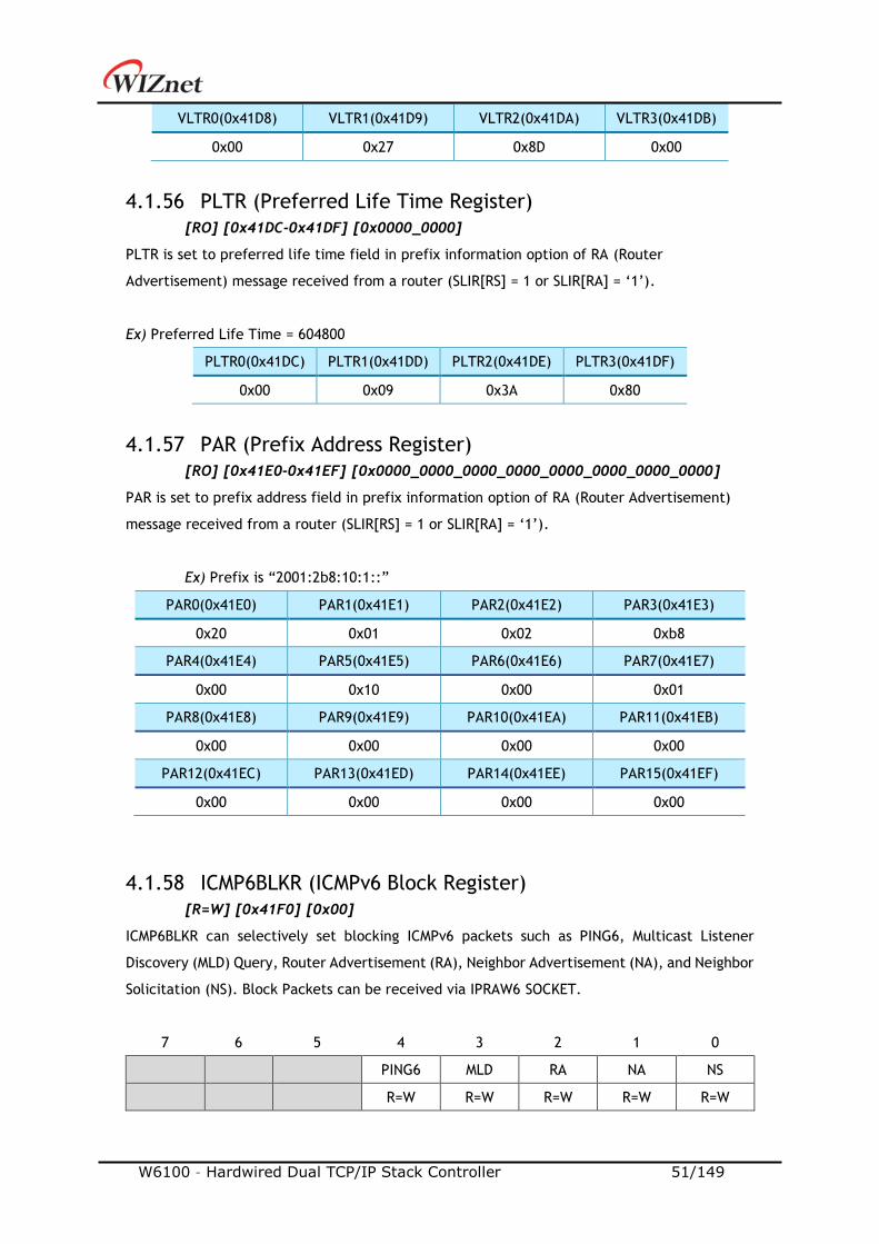
W6100 – Hardwired Dual TCP/IP Stack Controller 51/149
VLTR0(0x41D8) VLTR1(0x41D9) VLTR2(0x41DA) VLTR3(0x41DB)
0x00 0x27 0x8D 0x00
4.1.56 PLTR (Preferred Life Time Register)
[RO] [0x41DC-0x41DF] [0x0000_0000]
PLTR is set to preferred life time field in prefix information option of RA (Router
Advertisement) message received from a router (SLIR[RS] = 1 or SLIR[RA] = ‘1’).
Ex) Preferred Life Time = 604800
PLTR0(0x41DC) PLTR1(0x41DD) PLTR2(0x41DE) PLTR3(0x41DF)
0x00 0x09 0x3A 0x80
4.1.57 PAR (Prefix Address Register)
[RO] [0x41E0-0x41EF] [0x0000_0000_0000_0000_0000_0000_0000_0000]
PAR is set to prefix address field in prefix information option of RA (Router Advertisement)
message received from a router (SLIR[RS] = 1 or SLIR[RA] = ‘1’).
Ex) Prefix is “2001:2b8:10:1::”
PAR0(0x41E0) PAR1(0x41E1) PAR2(0x41E2) PAR3(0x41E3)
0x20 0x01 0x02 0xb8
PAR4(0x41E4) PAR5(0x41E5) PAR6(0x41E6) PAR7(0x41E7)
0x00 0x10 0x00 0x01
PAR8(0x41E8) PAR9(0x41E9) PAR10(0x41EA) PAR11(0x41EB)
0x00 0x00 0x00 0x00
PAR12(0x41EC) PAR13(0x41ED) PAR14(0x41EE) PAR15(0x41EF)
0x00 0x00 0x00 0x00
4.1.58 ICMP6BLKR (ICMPv6 Block Register)
[R=W] [0x41F0] [0x00]
ICMP6BLKR can selectively set blocking ICMPv6 packets such as PING6, Multicast Listener
Discovery (MLD) Query, Router Advertisement (RA), Neighbor Advertisement (NA), and Neighbor
Solicitation (NS). Block Packets can be received via IPRAW6 SOCKET.
7 6 5 4 3 2 1 0
PING6 MLD RA NA NS
R=W R=W R=W R=W R=W

W6100 – Hardwired Dual TCP/IP Stack Controller 52/149
Bit Symbol Description
[7:5] - Reserved
4 PING6
ICMPv6 Echo Request Block
1 : Block Echo Request Packet
0 : Normal Operation
3 MLD
ICMPv6 Multicast Listener Discovery(MLD) Query Block
1 : Block Multicast Listener Discovery Query Packet
0 : Normal Operation
2 RA
ICMPv6 Router Advertisement Block
1 : Block Router Advertisement Packet
0 : Normal Operation
1 NA
ICMPv6 Neighbor Advertisement Block
1 : Block Neighbor Advertisement Packet
0 : Normal Operation
0 NS
ICMPv6 Neighbor Solicitation Block
1 : Block Neighbor Solicitation Packet
0 : Normal Operation
4.1.59 CHPLCKR (Chip Lock Register)
[WO] [0x41F4] [0x00]
CHPLCKR sets SYSR[CHPL].
If SYSR [CHPL] is 'Unlock', SYCR0 and SYCR1 can be set.
Unlock Lock
0xCE Others
4.1.60 NETLCKR (Network Lock Register)
[WO] [0x41F5] [0x00]
NETLCKR sets SYSR[NETL].
If SYSR [NETL] is 'Unlock', Network Configuration Registers (SHAR, GAR, SUBR, SIPR, LLAR, GUAR,
SUB6R) can be set.
Unlock Lock
0x3A 0xC5
4.1.61 PHYLCKR (PHY Lock Register)
[WO] [0x41F6] [0x00]
PHYLCKR sets SYSR[PHYL].
If SYSR[PHYL] is ‘Unlock’, PHYCR0 and PHYCR1 can be set.
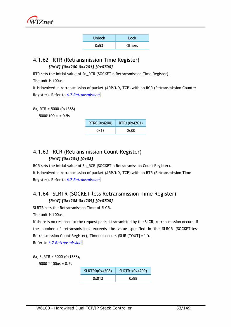
W6100 – Hardwired Dual TCP/IP Stack Controller 53/149
Unlock Lock
0x53 Others
4.1.62 RTR (Retransmission Time Register)
[R=W] [0x4200-0x4201] [0x07D0]
RTR sets the initial value of Sn_RTR (SOCKET n Retransmission Time Register).
The unit is 100us.
It is involved in retransmission of packet (ARP/ND, TCP) with an RCR (Retransmission Counter
Register). Refer to 6.7 Retransmission.
Ex) RTR = 5000 (0x1388)
5000*100us = 0.5s
RTR0(0x4200) RTR1(0x4201)
0x13 0x88
4.1.63 RCR (Retransmission Count Register)
[R=W] [0x4204] [0x08]
RCR sets the initial value of Sn_RCR (SOCKET n Retransmission Count Register).
It is involved in retransmission of packet (ARP/ND, TCP) with an RTR (Retransmission Time
Register). Refer to 6.7 Retransmission.
4.1.64 SLRTR (SOCKET-less Retransmission Time Register)
[R=W] [0x4208-0x4209] [0x07D0]
SLRTR sets the Retransmission Time of SLCR.
The unit is 100us.
If there is no response to the request packet transmitted by the SLCR, retransmission occurs. If
the number of retransmissions exceeds the value specified in the SLRCR (SOCKET-less
Retransmission Count Register), Timeout occurs (SLIR [TOUT] = '1').
Refer to 6.7 Retransmission.
Ex) SLRTR = 5000 (0x1388),
5000 * 100us = 0.5s
SLRTR0(0x4208) SLRTR1(0x4209)
0x013 0x88
W6100 – Hardwired Dual TCP/IP Stack Controller 54/149
4.1.65 SLRCR (SOCKET-less Retransmission Count Register)
[R=W] [0x420C] [0x00]
The SLRCR sets the Retransmission Counter of the SLCR.
If the retransmission counter exceeds SLRCR, SLIR [TOUT] becomes '1'.
Refer to 6.7 Retransmission.
4.1.66 SLHOPR (Hop limit Register)
[RW] [0x420F] [0x80]
Sets the HOP of ND Messages (NS, NA) transmitted by SLCR.
Ex) SLHOPR = 128
SLHOPR(0x420F)
0x80 (128)
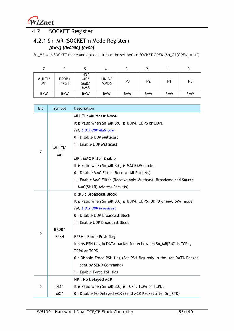
W6100 – Hardwired Dual TCP/IP Stack Controller 55/149
4.2 SOCKET Register
4.2.1 Sn_MR (SOCKET n Mode Register)
[R=W] [0x0000] [0x00]
Sn_MR sets SOCKET mode and options. It must be set before SOCKET OPEN (Sn_CR[OPEN] = ‘1’).
7 6 5 4 3 2 1 0
MULTI/ MF
BRDB/ FPSH
ND/ MC/ SMB/ MMB
UNIB/ MMB6
P3 P2 P1 P0
R=W R=W R=W R=W R=W R=W R=W R=W
Bit Symbol Description
7 MULTI/
MF
MULTI : Multicast Mode
It is valid when Sn_MR[3:0] is UDP4, UDP6 or UDPD.
ref) 6.3.3 UDP Multicast
0 : Disable UDP Multicast
1 : Enable UDP Multicast
MF : MAC Filter Enable
It is valid when Sn_MR[3:0] is MACRAW mode.
0 : Disable MAC Filter (Receive All Packets)
1 : Enable MAC Filter (Receive only Multicast, Broadcast and Source
MAC(SHAR) Address Packets)
6 BRDB/
FPSH
BRDB : Broadcast Block
It is valid when Sn_MR[3:0] is UDP4, UDP6, UDPD or MACRAW mode.
ref) 6.3.2 UDP Broadcast
0 : Disable UDP Broadcast Block
1 : Enable UDP Broadcast Block
FPSH : Force Push flag
It sets PSH flag in DATA packet forcedly when Sn_MR[3:0] is TCP4,
TCP6 or TCPD.
0 : Disable Force PSH flag (Set PSH flag only in the last DATA Packet
sent by SEND Command)
1 : Enable Force PSH flag
5
ND/
MC/
ND : No Delayed ACK
It is valid when Sn_MR[3:0] is TCP4, TCP6 or TCPD.
0 : Disable No Delayed ACK (Send ACK Packet after Sn_RTR)
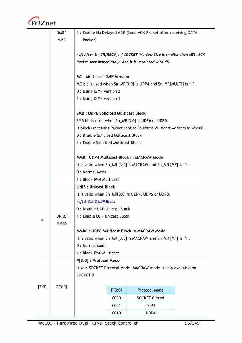
W6100 – Hardwired Dual TCP/IP Stack Controller 56/149
SMB/
MMB
1 : Enable No Delayed ACK (Send ACK Packet after receiving DATA
Packet)
ref) After Sn_CR[RECV], if SOCKET Window Size is smaller than MSS, ACK
Packet sent immediately. And it is unrelated with ND.
MC : Multicast IGMP Version
MC bit is used when Sn_MR[3:0] is UDP4 and Sn_MR[MULTI] is ‘1’.
0 : Using IGMP version 2
1 : Using IGMP version 1
SMB : UDP6 Solicited Multicast Block
SMB bit is used when Sn_MR[3:0] is UDP6 or UDPD.
It blocks receiving Packet sent to Solicited Multicast Address in W6100.
0 : Disable Solicited Multicast Block
1 : Enable Solicited Multicast Block
MMB : UDP4 Multicast Block in MACRAW Mode
It is valid when Sn_MR [3:0] is MACRAW and Sn_MR [MF] is ‘1’.
0 : Normal Mode
1 : Block IPv4 Multicast
4 UNIB/
MMB6
UNIB : Unicast Block
It is valid when Sn_MR[3:0] is UDP4, UDP6 or UDPD.
ref) 6.3.5.2 UDP Block
0 : Disable UDP Unicast Block
1 : Enable UDP Unicast Block
MMB6 : UDP6 Multicast Block in MACRAW Mode
It is valid when Sn_MR [3:0] is MACRAW and Sn_MR [MF] is ‘1’.
0 : Normal Mode
1 : Block IPv6 Multicast
[3:0] P[3:0]
P[3:0] : Protocol Mode
It sets SOCKET Protocol Mode. MACRAW mode is only available on
SOCKET 0.
P[3:0] Protocol Mode
0000 SOCKET Closed
0001 TCP4
0010 UDP4
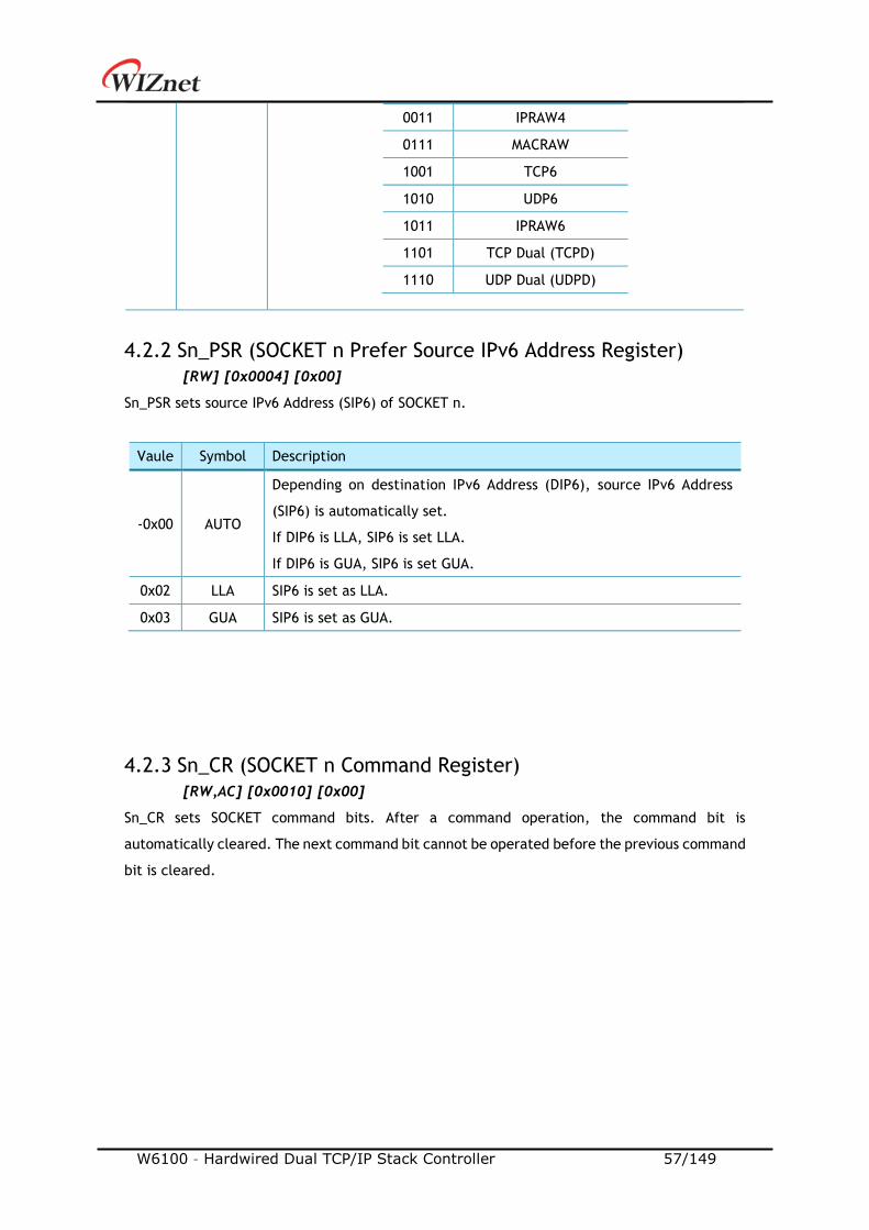
W6100 – Hardwired Dual TCP/IP Stack Controller 57/149
0011 IPRAW4
0111 MACRAW
1001 TCP6
1010 UDP6
1011 IPRAW6
1101 TCP Dual (TCPD)
1110 UDP Dual (UDPD)
4.2.2 Sn_PSR (SOCKET n Prefer Source IPv6 Address Register)
[RW] [0x0004] [0x00]
Sn_PSR sets source IPv6 Address (SIP6) of SOCKET n.
Vaule Symbol Description
-0x00 AUTO
Depending on destination IPv6 Address (DIP6), source IPv6 Address
(SIP6) is automatically set.
If DIP6 is LLA, SIP6 is set LLA.
If DIP6 is GUA, SIP6 is set GUA.
0x02 LLA SIP6 is set as LLA.
0x03 GUA SIP6 is set as GUA.
4.2.3 Sn_CR (SOCKET n Command Register)
[RW,AC] [0x0010] [0x00]
Sn_CR sets SOCKET command bits. After a command operation, the command bit is
automatically cleared. The next command bit cannot be operated before the previous command
bit is cleared.
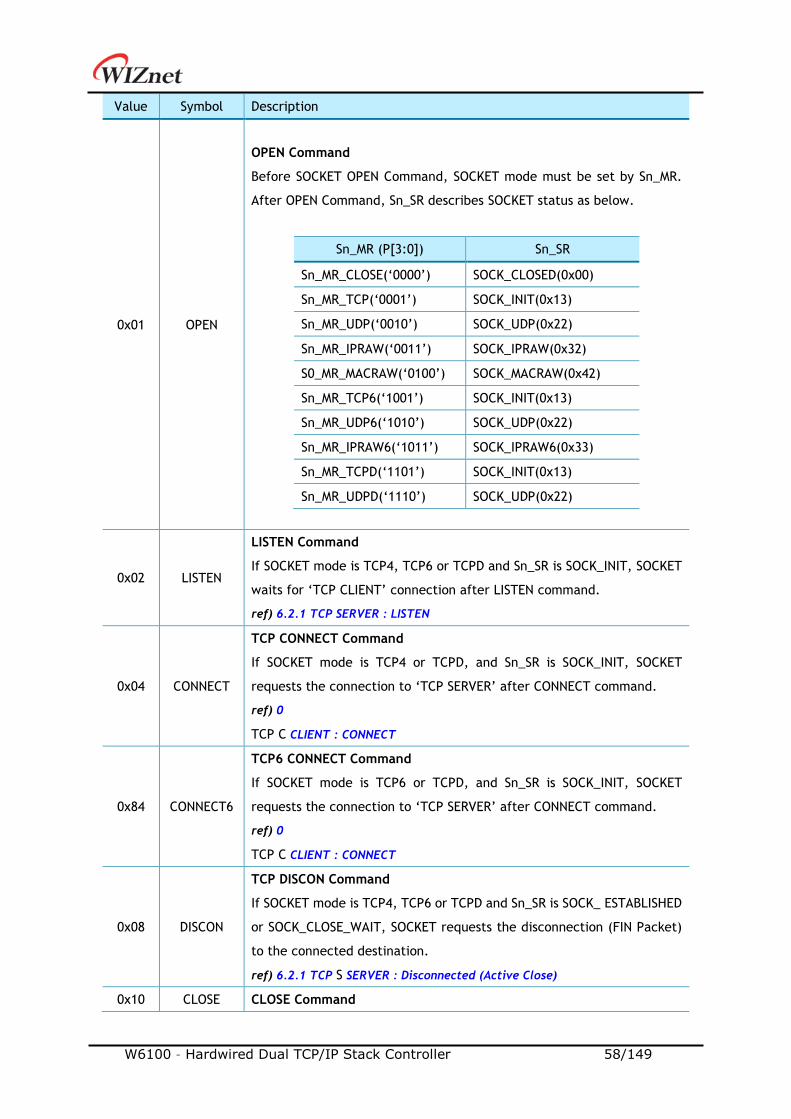
W6100 – Hardwired Dual TCP/IP Stack Controller 58/149
Value Symbol Description
0x01 OPEN
OPEN Command
Before SOCKET OPEN Command, SOCKET mode must be set by Sn_MR.
After OPEN Command, Sn_SR describes SOCKET status as below.
Sn_MR (P[3:0]) Sn_SR
Sn_MR_CLOSE(‘0000’) SOCK_CLOSED(0x00)
Sn_MR_TCP(‘0001’) SOCK_INIT(0x13)
Sn_MR_UDP(‘0010’) SOCK_UDP(0x22)
Sn_MR_IPRAW(‘0011’) SOCK_IPRAW(0x32)
S0_MR_MACRAW(‘0100’) SOCK_MACRAW(0x42)
Sn_MR_TCP6(‘1001’) SOCK_INIT(0x13)
Sn_MR_UDP6(‘1010’) SOCK_UDP(0x22)
Sn_MR_IPRAW6(‘1011’) SOCK_IPRAW6(0x33)
Sn_MR_TCPD(‘1101’) SOCK_INIT(0x13)
Sn_MR_UDPD(‘1110’) SOCK_UDP(0x22)
0x02 LISTEN
LISTEN Command
If SOCKET mode is TCP4, TCP6 or TCPD and Sn_SR is SOCK_INIT, SOCKET
waits for ‘TCP CLIENT’ connection after LISTEN command.
ref) 6.2.1 TCP SERVER : LISTEN
0x04 CONNECT
TCP CONNECT Command
If SOCKET mode is TCP4 or TCPD, and Sn_SR is SOCK_INIT, SOCKET
requests the connection to ‘TCP SERVER’ after CONNECT command.
ref) 0
TCP C CLIENT : CONNECT
0x84 CONNECT6
TCP6 CONNECT Command
If SOCKET mode is TCP6 or TCPD, and Sn_SR is SOCK_INIT, SOCKET
requests the connection to ‘TCP SERVER’ after CONNECT command.
ref) 0
TCP C CLIENT : CONNECT
0x08 DISCON
TCP DISCON Command
If SOCKET mode is TCP4, TCP6 or TCPD and Sn_SR is SOCK_ ESTABLISHED
or SOCK_CLOSE_WAIT, SOCKET requests the disconnection (FIN Packet)
to the connected destination.
ref) 6.2.1 TCP S SERVER : Disconnected (Active Close)
0x10 CLOSE CLOSE Command
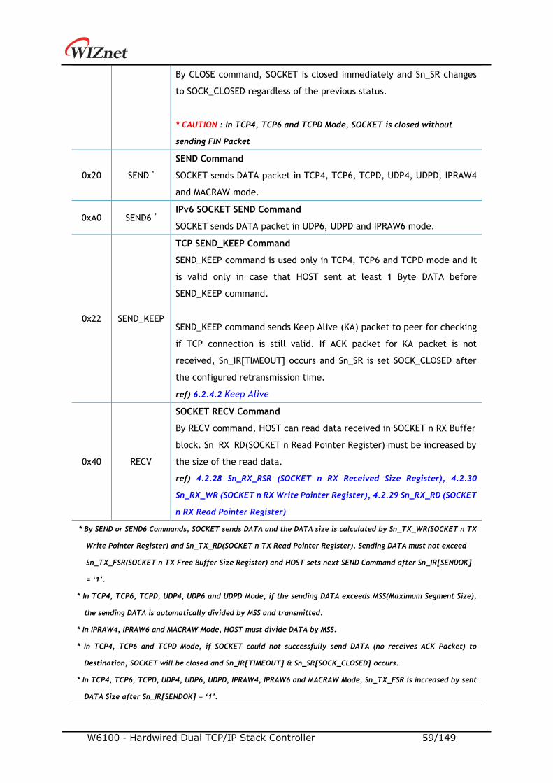
W6100 – Hardwired Dual TCP/IP Stack Controller 59/149
By CLOSE command, SOCKET is closed immediately and Sn_SR changes
to SOCK_CLOSED regardless of the previous status.
* CAUTION : In TCP4, TCP6 and TCPD Mode, SOCKET is closed without
sending FIN Packet
0x20 SEND *
SEND Command
SOCKET sends DATA packet in TCP4, TCP6, TCPD, UDP4, UDPD, IPRAW4
and MACRAW mode.
0xA0 SEND6 * IPv6 SOCKET SEND Command
SOCKET sends DATA packet in UDP6, UDPD and IPRAW6 mode.
0x22 SEND_KEEP
TCP SEND_KEEP Command
SEND_KEEP command is used only in TCP4, TCP6 and TCPD mode and It
is valid only in case that HOST sent at least 1 Byte DATA before
SEND_KEEP command.
SEND_KEEP command sends Keep Alive (KA) packet to peer for checking
if TCP connection is still valid. If ACK packet for KA packet is not
received, Sn_IR[TIMEOUT] occurs and Sn_SR is set SOCK_CLOSED after
the configured retransmission time.
ref) 6.2.4.2 Keep Alive
0x40 RECV
SOCKET RECV Command
By RECV command, HOST can read data received in SOCKET n RX Buffer
block. Sn_RX_RD(SOCKET n Read Pointer Register) must be increased by
the size of the read data.
ref) 4.2.28 Sn_RX_RSR (SOCKET n RX Received Size Register), 4.2.30
Sn_RX_WR (SOCKET n RX Write Pointer Register), 4.2.29 Sn_RX_RD (SOCKET
n RX Read Pointer Register)
* By SEND or SEND6 Commands, SOCKET sends DATA and the DATA size is calculated by Sn_TX_WR(SOCKET n TX
Write Pointer Register) and Sn_TX_RD(SOCKET n TX Read Pointer Register). Sending DATA must not exceed
Sn_TX_FSR(SOCKET n TX Free Buffer Size Register) and HOST sets next SEND Command after Sn_IR[SENDOK]
= ‘1’.
* In TCP4, TCP6, TCPD, UDP4, UDP6 and UDPD Mode, if the sending DATA exceeds MSS(Maximum Segment Size),
the sending DATA is automatically divided by MSS and transmitted.
* In IPRAW4, IPRAW6 and MACRAW Mode, HOST must divide DATA by MSS.
* In TCP4, TCP6 and TCPD Mode, if SOCKET could not successfully send DATA (no receives ACK Packet) to
Destination, SOCKET will be closed and Sn_IR[TIMEOUT] & Sn_SR[SOCK_CLOSED] occurs.
* In TCP4, TCP6, TCPD, UDP4, UDP6, UDPD, IPRAW4, IPRAW6 and MACRAW Mode, Sn_TX_FSR is increased by sent
DATA Size after Sn_IR[SENDOK] = ‘1’.

W6100 – Hardwired Dual TCP/IP Stack Controller 60/149
4.2.4 Sn_IR (SOCKET n Interrupt Register)
[RO] [0x0020] [0x00]
Sn_IR describes the status of SOCKET n or the results of Sn_CR.
If an event registered in Sn_IR occurs and the corresponding masking bit in Sn_IMR is set,
SIR[Sn_INT] is set by ‘1’.
7 6 5 4 3 2 1 0
- - - SENDOK TIMEOUT RECV DISCON CON
RO RO RO RO RO
Bit Symbol Description
[7:5] - Reserved
4 SENDOK SEND OK Interrupt
It is set by ‘1’ after Sn_CR[SEND] complete.
3 TIMEOUT
TIMEOUT Interrupt
When the count of retransmission exceeds Sn_RCR (SOCKERT n
Retransmission Count Register) in ARP/ND or TCP communication, it is
set by ‘1’.
2 RECV
RECEIVED Interrupt
When SOCKET received DATA or when DATA still remained in SOCKET
n buffer block after Sn_CR[RECV], it is set by ‘1’.
1 DISCON
DISCONNECTED Interrupt
When SOCKET received FIN or RST Packet or when SOCKET received
ACK packet for FIN packet sent by Sn_CR[DISCON], it is set by ‘1’.
0 CON
CONNECTED Interrupt
When TCP connection is established by Sn_CR[CONNECT], Sn_CR
[CONNECT6] or by receiving SYN packet from destination, it is set by
‘1’.
4.2.5 Sn_IMR (SOCKET n Interrupt Mask Register)
[R=W] [0x0024] [0xFF]
Sn_IMR is used for the corresponding Sn_IR bit mask.
7 6 5 4 3 2 1 0
- - - SENDOK TIMEOUT RECV DISCON CON
- - - R=W R=W R=W R=W R=W
Bit Symbol Description
[7:5] - Reserved
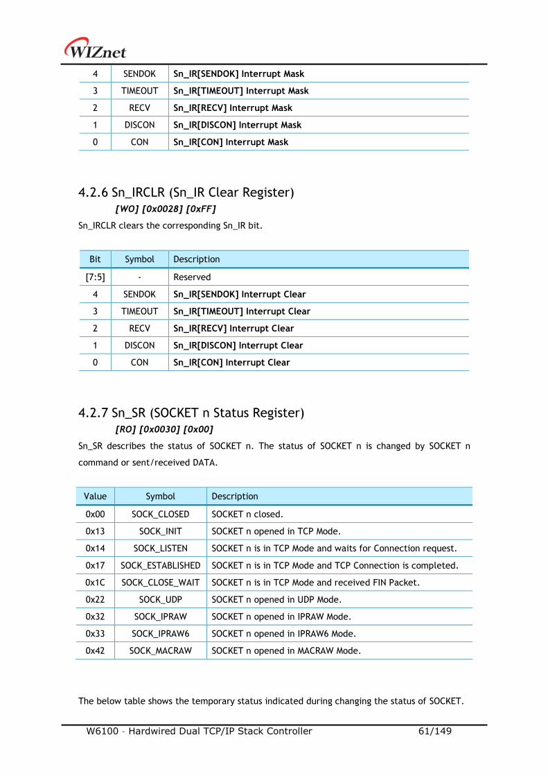
W6100 – Hardwired Dual TCP/IP Stack Controller 61/149
4 SENDOK Sn_IR[SENDOK] Interrupt Mask
3 TIMEOUT Sn_IR[TIMEOUT] Interrupt Mask
2 RECV Sn_IR[RECV] Interrupt Mask
1 DISCON Sn_IR[DISCON] Interrupt Mask
0 CON Sn_IR[CON] Interrupt Mask
4.2.6 Sn_IRCLR (Sn_IR Clear Register)
[WO] [0x0028] [0xFF]
Sn_IRCLR clears the corresponding Sn_IR bit.
Bit Symbol Description
[7:5] - Reserved
4 SENDOK Sn_IR[SENDOK] Interrupt Clear
3 TIMEOUT Sn_IR[TIMEOUT] Interrupt Clear
2 RECV Sn_IR[RECV] Interrupt Clear
1 DISCON Sn_IR[DISCON] Interrupt Clear
0 CON Sn_IR[CON] Interrupt Clear
4.2.7 Sn_SR (SOCKET n Status Register)
[RO] [0x0030] [0x00]
Sn_SR describes the status of SOCKET n. The status of SOCKET n is changed by SOCKET n
command or sent/received DATA.
Value Symbol Description
0x00 SOCK_CLOSED SOCKET n closed.
0x13 SOCK_INIT SOCKET n opened in TCP Mode.
0x14 SOCK_LISTEN SOCKET n is in TCP Mode and waits for Connection request.
0x17 SOCK_ESTABLISHED SOCKET n is in TCP Mode and TCP Connection is completed.
0x1C SOCK_CLOSE_WAIT SOCKET n is in TCP Mode and received FIN Packet.
0x22 SOCK_UDP SOCKET n opened in UDP Mode.
0x32 SOCK_IPRAW SOCKET n opened in IPRAW Mode.
0x33 SOCK_IPRAW6 SOCKET n opened in IPRAW6 Mode.
0x42 SOCK_MACRAW SOCKET n opened in MACRAW Mode.
The below table shows the temporary status indicated during changing the status of SOCKET.

W6100 – Hardwired Dual TCP/IP Stack Controller 62/149
Value Symbol Description
0x15 SOCK_SYNSENT The status of sending Connect-Request.
0x16 SOCK_SYNRECV The status of receiving Connect-Request.
0x18 SOCK_FIN_WAIT
The status of closing SOCKET n. 0X1B SOCK_TIME_WAIT
0X1D SOCK_LAST_ACK
Figure 4 State Diagram
4.2.8 Sn_ESR (SOCKET n Extension Status Register)
[RO] [0x0031] [0x00]
Sn_ESR indicates SOCKET n extension status in TCP4, TCP6 and TCPD mode.
7 6 5 4 3 2 1 0
- - - - - TCPM SVR GUA
- - - - - RO RO RO
Bit Symbol Description
[7:3] - Reserved
2 TCPM TCP Mode
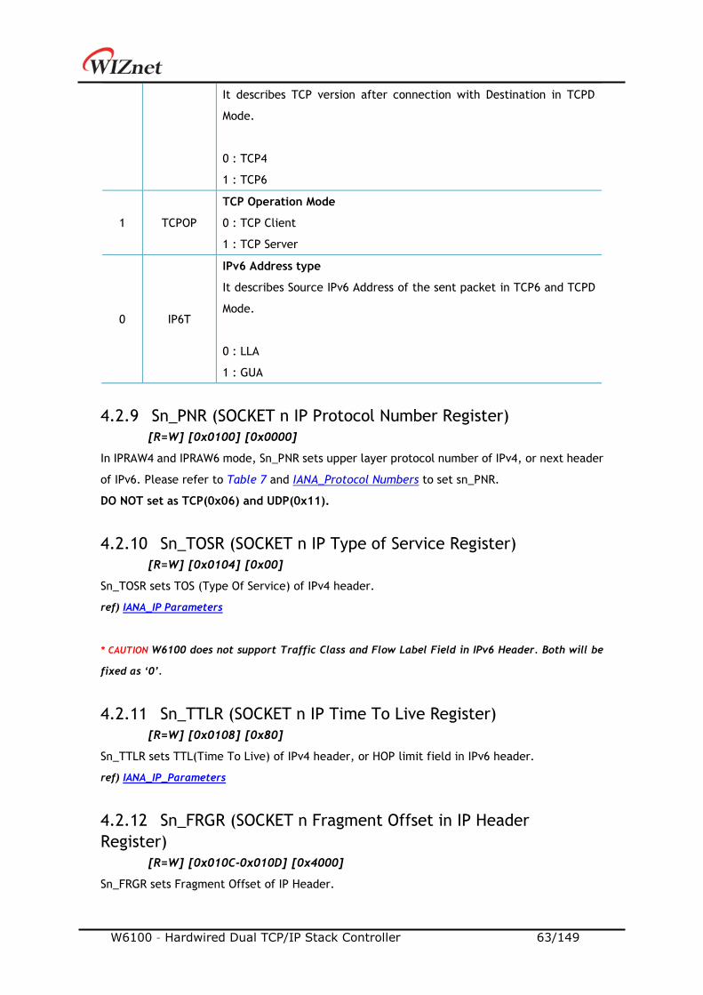
W6100 – Hardwired Dual TCP/IP Stack Controller 63/149
It describes TCP version after connection with Destination in TCPD
Mode.
0 : TCP4
1 : TCP6
1 TCPOP
TCP Operation Mode
0 : TCP Client
1 : TCP Server
0 IP6T
IPv6 Address type
It describes Source IPv6 Address of the sent packet in TCP6 and TCPD
Mode.
0 : LLA
1 : GUA
4.2.9 Sn_PNR (SOCKET n IP Protocol Number Register)
[R=W] [0x0100] [0x0000]
In IPRAW4 and IPRAW6 mode, Sn_PNR sets upper layer protocol number of IPv4, or next header
of IPv6. Please refer to Table 7 and IANA_Protocol Numbers to set sn_PNR.
DO NOT set as TCP(0x06) and UDP(0x11).
4.2.10 Sn_TOSR (SOCKET n IP Type of Service Register)
[R=W] [0x0104] [0x00]
Sn_TOSR sets TOS (Type Of Service) of IPv4 header.
ref) IANA_IP Parameters
* CAUTION W6100 does not support Traffic Class and Flow Label Field in IPv6 Header. Both will be
fixed as ‘0’.
4.2.11 Sn_TTLR (SOCKET n IP Time To Live Register)
[R=W] [0x0108] [0x80]
Sn_TTLR sets TTL(Time To Live) of IPv4 header, or HOP limit field in IPv6 header.
ref) IANA_IP_Parameters
4.2.12 Sn_FRGR (SOCKET n Fragment Offset in IP Header
Register)
[R=W] [0x010C-0x010D] [0x4000]
Sn_FRGR sets Fragment Offset of IP Header.
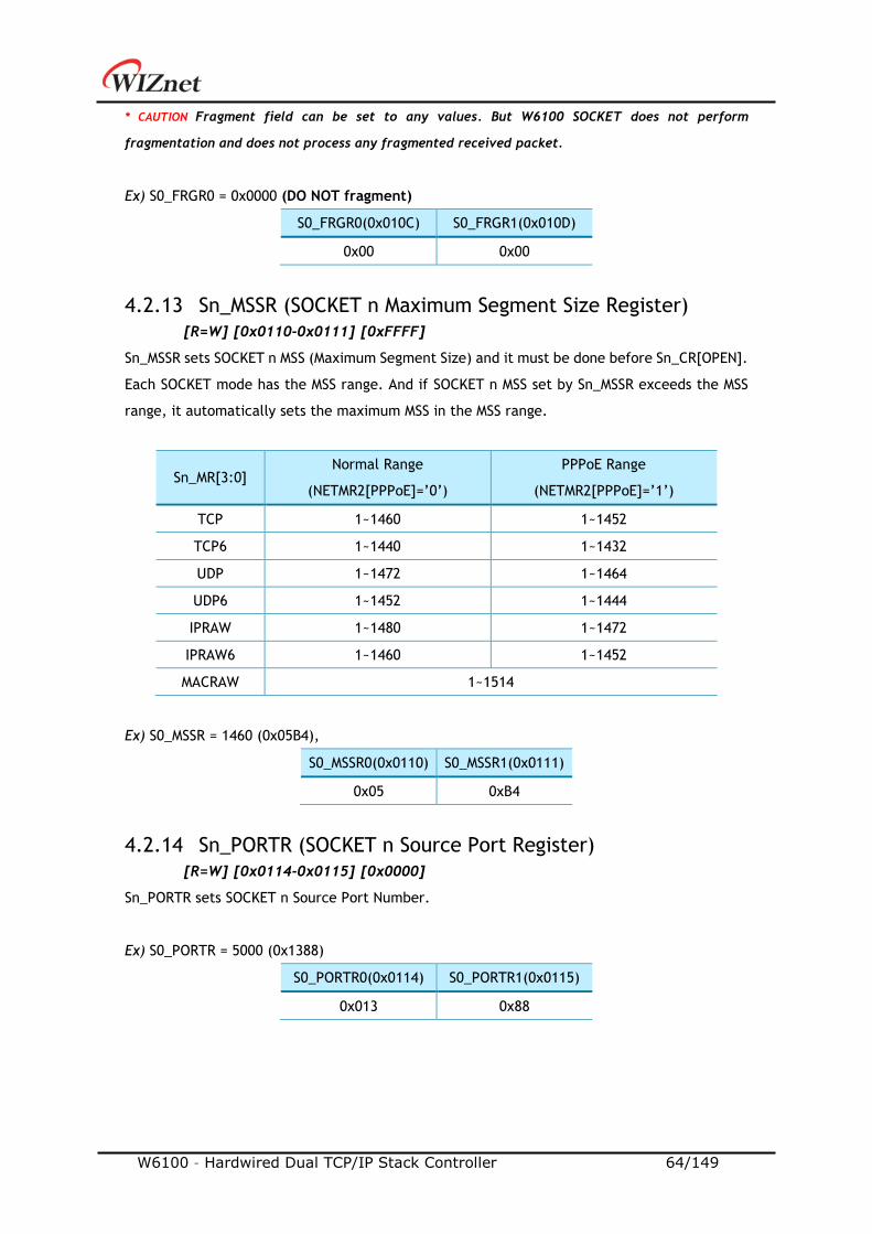
W6100 – Hardwired Dual TCP/IP Stack Controller 64/149
* CAUTION Fragment field can be set to any values. But W6100 SOCKET does not perform
fragmentation and does not process any fragmented received packet.
Ex) S0_FRGR0 = 0x0000 (DO NOT fragment)
S0_FRGR0(0x010C) S0_FRGR1(0x010D)
0x00 0x00
4.2.13 Sn_MSSR (SOCKET n Maximum Segment Size Register)
[R=W] [0x0110-0x0111] [0xFFFF]
Sn_MSSR sets SOCKET n MSS (Maximum Segment Size) and it must be done before Sn_CR[OPEN].
Each SOCKET mode has the MSS range. And if SOCKET n MSS set by Sn_MSSR exceeds the MSS
range, it automatically sets the maximum MSS in the MSS range.
Sn_MR[3:0] Normal Range
(NETMR2[PPPoE]=’0’)
PPPoE Range
(NETMR2[PPPoE]=’1’)
TCP 1~1460 1~1452
TCP6 1~1440 1~1432
UDP 1~1472 1~1464
UDP6 1~1452 1~1444
IPRAW 1~1480 1~1472
IPRAW6 1~1460 1~1452
MACRAW 1~1514
Ex) S0_MSSR = 1460 (0x05B4),
S0_MSSR0(0x0110) S0_MSSR1(0x0111)
0x05 0xB4
4.2.14 Sn_PORTR (SOCKET n Source Port Register)
[R=W] [0x0114-0x0115] [0x0000]
Sn_PORTR sets SOCKET n Source Port Number.
Ex) S0_PORTR = 5000 (0x1388)
S0_PORTR0(0x0114) S0_PORTR1(0x0115)
0x013 0x88
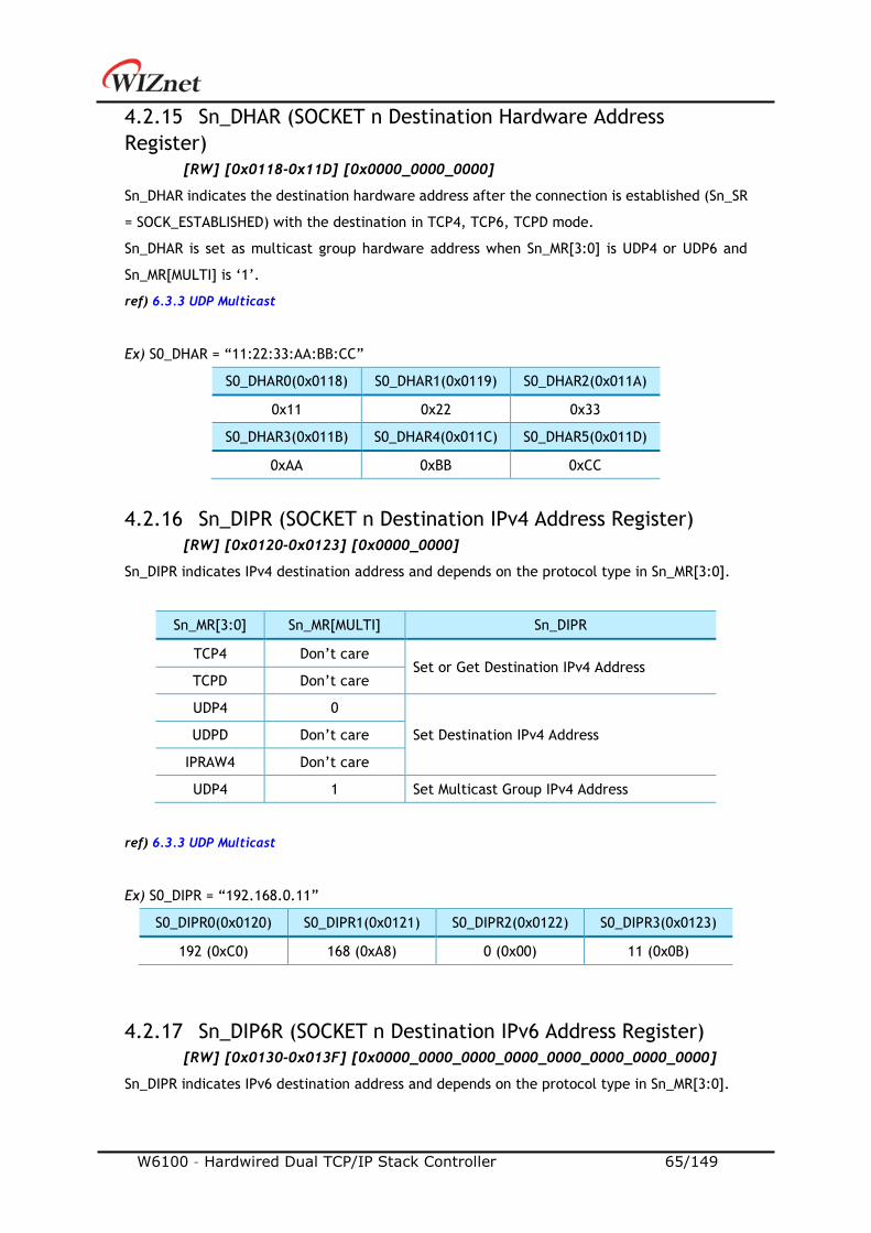
W6100 – Hardwired Dual TCP/IP Stack Controller 65/149
4.2.15 Sn_DHAR (SOCKET n Destination Hardware Address
Register)
[RW] [0x0118-0x11D] [0x0000_0000_0000]
Sn_DHAR indicates the destination hardware address after the connection is established (Sn_SR
= SOCK_ESTABLISHED) with the destination in TCP4, TCP6, TCPD mode.
Sn_DHAR is set as multicast group hardware address when Sn_MR[3:0] is UDP4 or UDP6 and
Sn_MR[MULTI] is ‘1’.
ref) 6.3.3 UDP Multicast
Ex) S0_DHAR = “11:22:33:AA:BB:CC”
S0_DHAR0(0x0118) S0_DHAR1(0x0119) S0_DHAR2(0x011A)
0x11 0x22 0x33
S0_DHAR3(0x011B) S0_DHAR4(0x011C) S0_DHAR5(0x011D)
0xAA 0xBB 0xCC
4.2.16 Sn_DIPR (SOCKET n Destination IPv4 Address Register)
[RW] [0x0120-0x0123] [0x0000_0000]
Sn_DIPR indicates IPv4 destination address and depends on the protocol type in Sn_MR[3:0].
Sn_MR[3:0] Sn_MR[MULTI] Sn_DIPR
TCP4 Don’t care Set or Get Destination IPv4 Address
TCPD Don’t care
UDP4 0
Set Destination IPv4 Address UDPD Don’t care
IPRAW4 Don’t care
UDP4 1 Set Multicast Group IPv4 Address
ref) 6.3.3 UDP Multicast
Ex) S0_DIPR = “192.168.0.11”
S0_DIPR0(0x0120) S0_DIPR1(0x0121) S0_DIPR2(0x0122) S0_DIPR3(0x0123)
192 (0xC0) 168 (0xA8) 0 (0x00) 11 (0x0B)
4.2.17 Sn_DIP6R (SOCKET n Destination IPv6 Address Register)
[RW] [0x0130-0x013F] [0x0000_0000_0000_0000_0000_0000_0000_0000]
Sn_DIPR indicates IPv6 destination address and depends on the protocol type in Sn_MR[3:0].

W6100 – Hardwired Dual TCP/IP Stack Controller 66/149
Sn_MR[3:0] Sn_MR[MULTI] Sn_DIP6R
TCP6 Don’t care Set or Get Destination IPv6 Address
TCPD Don’t care
UDP6 0
Set Destination IPv6 Address UDPD Don’t care
IPRAW6 Don’t care
UDP6 1 Set Multicast Group IPv6 Address
ref) 6.3.3 UDP Multicast
Ex) Destination IP is “FE80::AB:CDEF”
S0_DIP6R0(0x0130) S0_DIP6R1(0x0131) S0_DIP6R2(0x0132) S0_DIP6R3(0x0133)
0xFE 0x80 0x00 0x00
S0_DIP6R4(0x0134) S0_DIP6R5(0x0135) S0_DIP6R6(0x0136) S0_DIP6R7(0x0137)
0x00 0x00 0x00 0x00
S0_DIP6R8(0x0138) S0_DIP6R9(0x0139) S0_DIP6R10(0x013A) S0_DIP6R11(0x013B)
0x00 0x00 0x00 0x00
S0_DIP6R12(0x013C) S0_DIP6R13(0x013D) S0_DIP6R14(0x013E) S0_DIP6R15(0x013F)
0x00 0xAB 0xCD 0xEF
4.2.18 Sn_DPORTR (SOCKET n Destination Port Register)
[R=W] [0x0140-0x0141] [0x0000]
Sn_DPORTR indicates destination port and depends on the protocol type in Sn_MR[3:0].
Sn_MR[3:0] Sn_MR[MULTI] Sn_DPORTR
TCP4 Don’t care
Set or Get Destination Port TCP6 Don’t care
TCPD Don’t care
UDP4 0
Set Destination Port
UDP6 0
UDPD Don’t care
IPRAW4 Don’t care
IPRAW6 Don’t care
UDP4 1 Set Multicast Group Port
UDP6 1
In TCP4, TCP6 and TCPD mode, Sn_DPORTR is set to the destination port or get the connected
destination port.
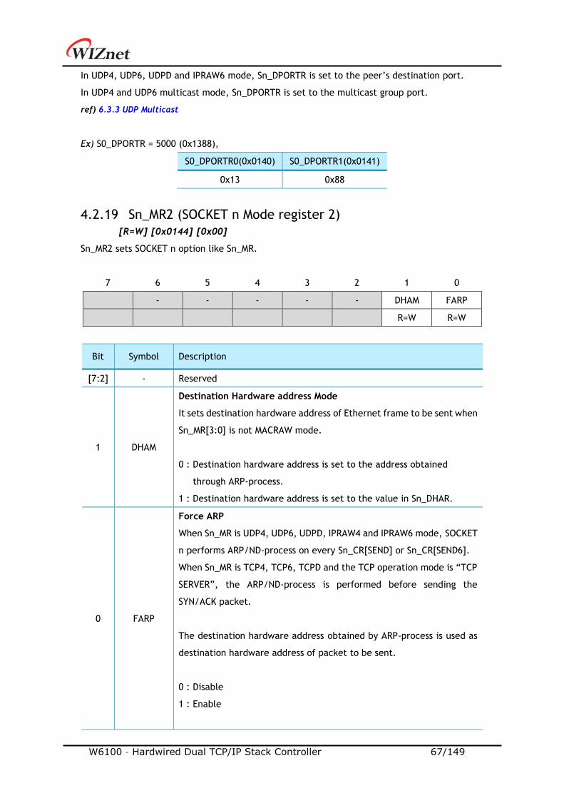
W6100 – Hardwired Dual TCP/IP Stack Controller 67/149
In UDP4, UDP6, UDPD and IPRAW6 mode, Sn_DPORTR is set to the peer’s destination port.
In UDP4 and UDP6 multicast mode, Sn_DPORTR is set to the multicast group port.
ref) 6.3.3 UDP Multicast
Ex) S0_DPORTR = 5000 (0x1388),
S0_DPORTR0(0x0140) S0_DPORTR1(0x0141)
0x13 0x88
4.2.19 Sn_MR2 (SOCKET n Mode register 2)
[R=W] [0x0144] [0x00]
Sn_MR2 sets SOCKET n option like Sn_MR.
7 6 5 4 3 2 1 0
- - - - - DHAM FARP
R=W R=W
Bit Symbol Description
[7:2] - Reserved
1 DHAM
Destination Hardware address Mode
It sets destination hardware address of Ethernet frame to be sent when
Sn_MR[3:0] is not MACRAW mode.
0 : Destination hardware address is set to the address obtained
through ARP-process.
1 : Destination hardware address is set to the value in Sn_DHAR.
0 FARP
Force ARP
When Sn_MR is UDP4, UDP6, UDPD, IPRAW4 and IPRAW6 mode, SOCKET
n performs ARP/ND-process on every Sn_CR[SEND] or Sn_CR[SEND6].
When Sn_MR is TCP4, TCP6, TCPD and the TCP operation mode is “TCP
SERVER”, the ARP/ND-process is performed before sending the
SYN/ACK packet.
The destination hardware address obtained by ARP-process is used as
destination hardware address of packet to be sent.
0 : Disable
1 : Enable
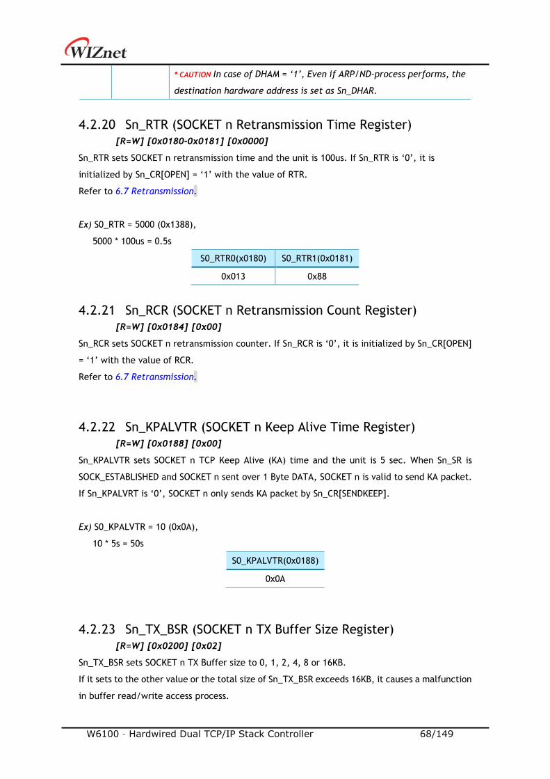
W6100 – Hardwired Dual TCP/IP Stack Controller 68/149
* CAUTION In case of DHAM = ‘1’, Even if ARP/ND-process performs, the
destination hardware address is set as Sn_DHAR.
4.2.20 Sn_RTR (SOCKET n Retransmission Time Register)
[R=W] [0x0180-0x0181] [0x0000]
Sn_RTR sets SOCKET n retransmission time and the unit is 100us. If Sn_RTR is ‘0’, it is
initialized by Sn_CR[OPEN] = ‘1’ with the value of RTR.
Refer to 6.7 Retransmission.
Ex) S0_RTR = 5000 (0x1388),
5000 * 100us = 0.5s
S0_RTR0(x0180) S0_RTR1(0x0181)
0x013 0x88
4.2.21 Sn_RCR (SOCKET n Retransmission Count Register)
[R=W] [0x0184] [0x00]
Sn_RCR sets SOCKET n retransmission counter. If Sn_RCR is ‘0’, it is initialized by Sn_CR[OPEN]
= ‘1’ with the value of RCR.
Refer to 6.7 Retransmission.
4.2.22 Sn_KPALVTR (SOCKET n Keep Alive Time Register)
[R=W] [0x0188] [0x00]
Sn_KPALVTR sets SOCKET n TCP Keep Alive (KA) time and the unit is 5 sec. When Sn_SR is
SOCK_ESTABLISHED and SOCKET n sent over 1 Byte DATA, SOCKET n is valid to send KA packet.
If Sn_KPALVRT is ‘0’, SOCKET n only sends KA packet by Sn_CR[SENDKEEP].
Ex) S0_KPALVTR = 10 (0x0A),
10 * 5s = 50s
S0_KPALVTR(0x0188)
0x0A
4.2.23 Sn_TX_BSR (SOCKET n TX Buffer Size Register)
[R=W] [0x0200] [0x02]
Sn_TX_BSR sets SOCKET n TX Buffer size to 0, 1, 2, 4, 8 or 16KB.
If it sets to the other value or the total size of Sn_TX_BSR exceeds 16KB, it causes a malfunction
in buffer read/write access process.
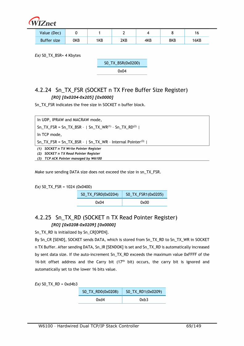
W6100 – Hardwired Dual TCP/IP Stack Controller 69/149
Value (Dec) 0 1 2 4 8 16
Buffer size 0KB 1KB 2KB 4KB 8KB 16KB
Ex) S0_TX_BSR= 4 Kbytes
S0_TX_BSR(0x0200)
0x04
4.2.24 Sn_TX_FSR (SOCKET n TX Free Buffer Size Register)
[RO] [0x0204-0x205] [0x0000]
Sn_TX_FSR indicates the free size in SOCKET n buffer block.
In UDP, IPRAW and MACRAW mode,
Sn_TX_FSR = Sn_TX_BSR – | Sn_TX_WR(1) – Sn_TX_RD(2) |
In TCP mode,
Sn_TX_FSR = Sn_TX_BSR – | Sn_TX_WR – Internal Pointer(3) |
(1) SOCKET n TX Write Pointer Register
(2) SOCKET n TX Read Pointer Register
(3) TCP ACK Pointer managed by W6100
Make sure sending DATA size does not exceed the size in sn_TX_FSR.
Ex) S0_TX_FSR = 1024 (0x0400)
S0_TX_FSR0(0x0204) S0_TX_FSR1(0x0205)
0x04 0x00
4.2.25 Sn_TX_RD (SOCKET n TX Read Pointer Register)
[RO] [0x0208-0x0209] [0x0000]
Sn_TX_RD is initialized by Sn_CR[OPEN].
By Sn_CR [SEND], SOCKET sends DATA, which is stored from Sn_TX_RD to Sn_TX_WR in SOCKET
n TX Buffer. After sending DATA, Sn_IR [SENDOK] is set and Sn_TX_RD is automatically increased
by sent data size. If the auto-increment Sn_TX_RD exceeds the maximum value 0xFFFF of the
16-bit offset address and the Carry bit (17th bit) occurs, the carry bit is ignored and
automatically set to the lower 16 bits value.
Ex) S0_TX_RD = 0xd4b3
S0_TX_RD0(0x0208) S0_TX_RD1(0x0209)
0xd4 0xb3
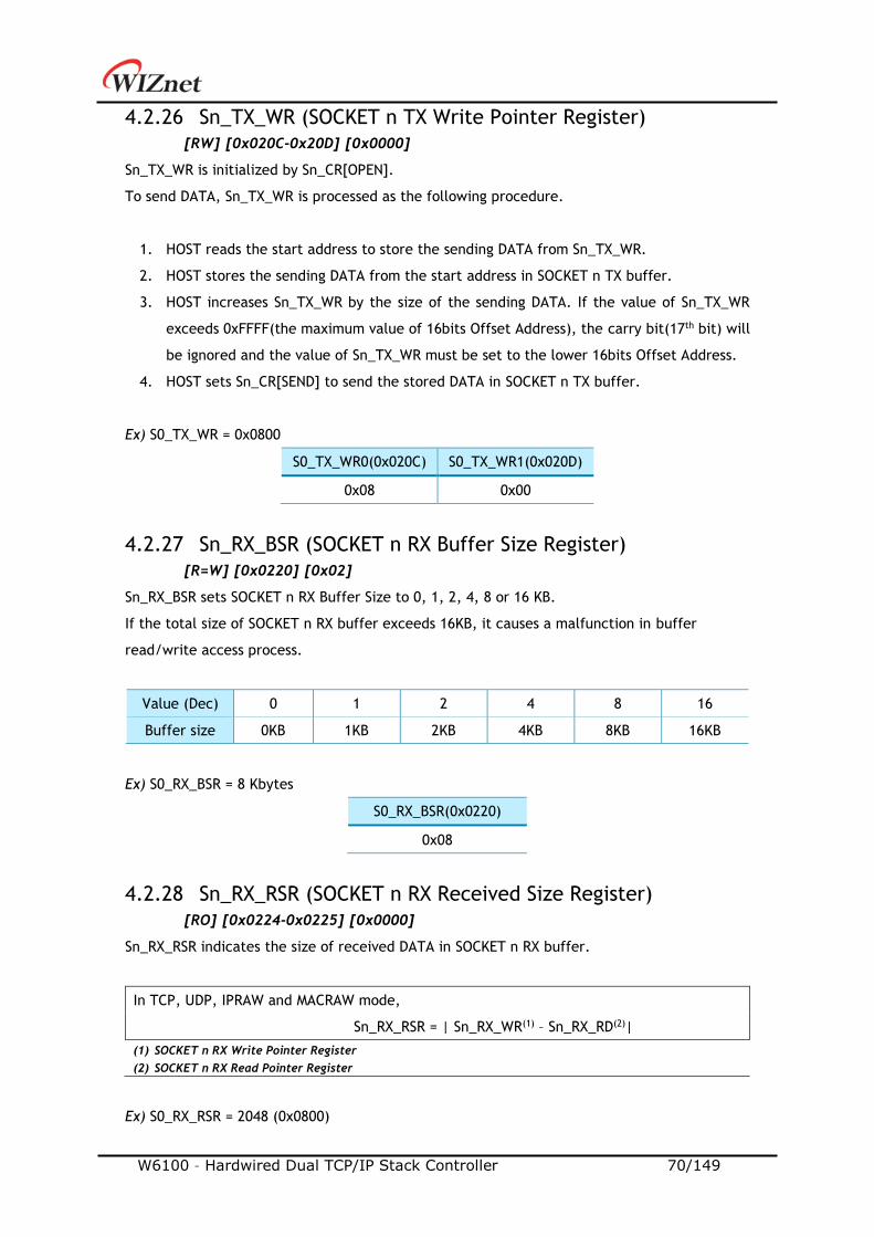
W6100 – Hardwired Dual TCP/IP Stack Controller 70/149
4.2.26 Sn_TX_WR (SOCKET n TX Write Pointer Register)
[RW] [0x020C-0x20D] [0x0000]
Sn_TX_WR is initialized by Sn_CR[OPEN].
To send DATA, Sn_TX_WR is processed as the following procedure.
1. HOST reads the start address to store the sending DATA from Sn_TX_WR.
2. HOST stores the sending DATA from the start address in SOCKET n TX buffer.
3. HOST increases Sn_TX_WR by the size of the sending DATA. If the value of Sn_TX_WR
exceeds 0xFFFF(the maximum value of 16bits Offset Address), the carry bit(17th bit) will
be ignored and the value of Sn_TX_WR must be set to the lower 16bits Offset Address.
4. HOST sets Sn_CR[SEND] to send the stored DATA in SOCKET n TX buffer.
Ex) S0_TX_WR = 0x0800
S0_TX_WR0(0x020C) S0_TX_WR1(0x020D)
0x08 0x00
4.2.27 Sn_RX_BSR (SOCKET n RX Buffer Size Register)
[R=W] [0x0220] [0x02]
Sn_RX_BSR sets SOCKET n RX Buffer Size to 0, 1, 2, 4, 8 or 16 KB.
If the total size of SOCKET n RX buffer exceeds 16KB, it causes a malfunction in buffer
read/write access process.
Value (Dec) 0 1 2 4 8 16
Buffer size 0KB 1KB 2KB 4KB 8KB 16KB
Ex) S0_RX_BSR = 8 Kbytes
S0_RX_BSR(0x0220)
0x08
4.2.28 Sn_RX_RSR (SOCKET n RX Received Size Register)
[RO] [0x0224-0x0225] [0x0000]
Sn_RX_RSR indicates the size of received DATA in SOCKET n RX buffer.
In TCP, UDP, IPRAW and MACRAW mode,
Sn_RX_RSR = | Sn_RX_WR(1) – Sn_RX_RD(2)|
(1) SOCKET n RX Write Pointer Register
(2) SOCKET n RX Read Pointer Register
Ex) S0_RX_RSR = 2048 (0x0800)
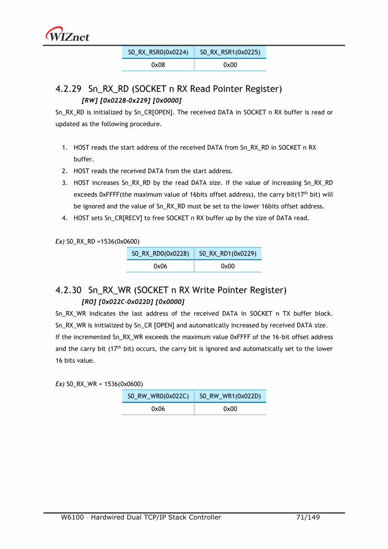
W6100 – Hardwired Dual TCP/IP Stack Controller 71/149
S0_RX_RSR0(0x0224) S0_RX_RSR1(0x0225)
0x08 0x00
4.2.29 Sn_RX_RD (SOCKET n RX Read Pointer Register)
[RW] [0x0228-0x229] [0x0000]
Sn_RX_RD is initialized by Sn_CR[OPEN]. The received DATA in SOCKET n RX buffer is read or
updated as the following procedure.
1. HOST reads the start address of the received DATA from Sn_RX_RD in SOCKET n RX
buffer.
2. HOST reads the received DATA from the start address.
3. HOST increases Sn_RX_RD by the read DATA size. If the value of increasing Sn_RX_RD
exceeds 0xFFFF(the maximum value of 16bits offset address), the carry bit(17th bit) will
be ignored and the value of Sn_RX_RD must be set to the lower 16bits offset address.
4. HOST sets Sn_CR[RECV] to free SOCKET n RX buffer up by the size of DATA read.
Ex) S0_RX_RD =1536(0x0600)
S0_RX_RD0(0x0228) S0_RX_RD1(0x0229)
0x06 0x00
4.2.30 Sn_RX_WR (SOCKET n RX Write Pointer Register)
[RO] [0x022C-0x022D] [0x0000]
Sn_RX_WR indicates the last address of the received DATA in SOCKET n TX buffer block.
Sn_RX_WR is initialized by Sn_CR [OPEN] and automatically increased by received DATA size.
If the incremented Sn_RX_WR exceeds the maximum value 0xFFFF of the 16-bit offset address
and the carry bit (17th bit) occurs, the carry bit is ignored and automatically set to the lower
16 bits value.
Ex) S0_RX_WR = 1536(0x0600)
S0_RW_WR0(0x022C) S0_RW_WR1(0x022D)
0x06 0x00
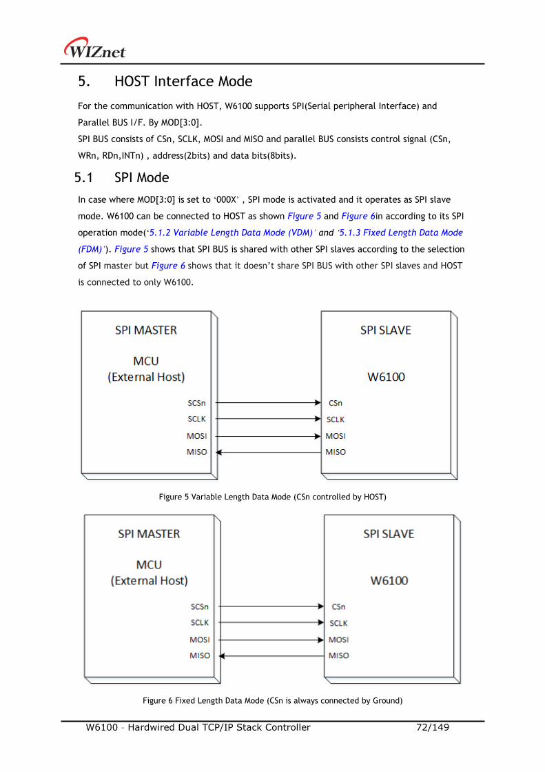
W6100 – Hardwired Dual TCP/IP Stack Controller 72/149
5. HOST Interface Mode
For the communication with HOST, W6100 supports SPI(Serial peripheral Interface) and
Parallel BUS I/F. By MOD[3:0].
SPI BUS consists of CSn, SCLK, MOSI and MISO and parallel BUS consists control signal (CSn,
WRn, RDn,INTn) , address(2bits) and data bits(8bits).
5.1 SPI Mode
In case where MOD[3:0] is set to ‘000X’ , SPI mode is activated and it operates as SPI slave
mode. W6100 can be connected to HOST as shown Figure 5 and Figure 6in according to its SPI
operation mode(‘5.1.2 Variable Length Data Mode (VDM)’ and ‘5.1.3 Fixed Length Data Mode
(FDM)’). Figure 5 shows that SPI BUS is shared with other SPI slaves according to the selection
of SPI master but Figure 6 shows that it doesn’t share SPI BUS with other SPI slaves and HOST
is connected to only W6100.
Figure 5 Variable Length Data Mode (CSn controlled by HOST)
Figure 6 Fixed Length Data Mode (CSn is always connected by Ground)
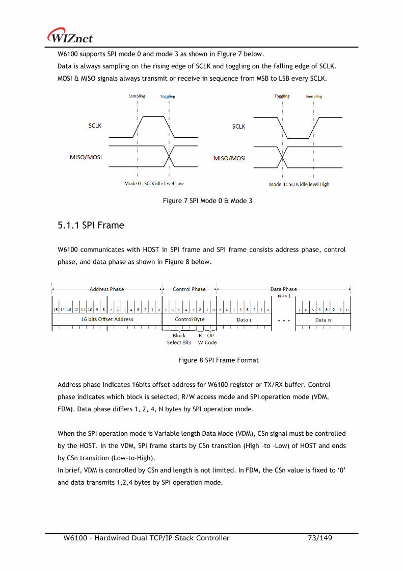
W6100 – Hardwired Dual TCP/IP Stack Controller 73/149
W6100 supports SPI mode 0 and mode 3 as shown in Figure 7 below.
Data is always sampling on the rising edge of SCLK and toggling on the falling edge of SCLK.
MOSI & MISO signals always transmit or receive in sequence from MSB to LSB every SCLK.
5.1.1 SPI Frame
W6100 communicates with HOST in SPI frame and SPI frame consists address phase, control
phase, and data phase as shown in Figure 8 below.
Address phase indicates 16bits offset address for W6100 register or TX/RX buffer. Control
phase indicates which block is selected, R/W access mode and SPI operation mode (VDM,
FDM). Data phase differs 1, 2, 4, N bytes by SPI operation mode.
When the SPI operation mode is Variable length Data Mode (VDM), CSn signal must be controlled
by the HOST. In the VDM, SPI frame starts by CSn transition (High –to –Low) of HOST and ends
by CSn transition (Low-to-High).
In brief, VDM is controlled by CSn and length is not limited. In FDM, the CSn value is fixed to ‘0’
and data transmits 1,2,4 bytes by SPI operation mode.
Figure 7 SPI Mode 0 & Mode 3
Figure 8 SPI Frame Format
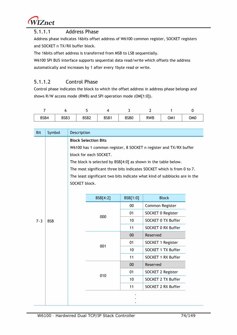
W6100 – Hardwired Dual TCP/IP Stack Controller 74/149
5.1.1.1 Address Phase
Address phase indicates 16bits offset address of W6100 common register, SOCKET registers
and SOCKET n TX/RX buffer block.
The 16bits offset address is transferred from MSB to LSB sequentially.
W6100 SPI BUS interface supports sequential data read/write which offsets the address
automatically and increases by 1 after every 1byte read or write.
5.1.1.2 Control Phase
Control phase indicates the block to which the offset address in address phase belongs and
shows R/W access mode (RWB) and SPI operation mode (OM[1:0]).
7 6 5 4 3 2 1 0
BSB4 BSB3 BSB2 BSB1 BSB0 RWB OM1 OM0
Bit Symbol Description
7~3 BSB
Block Selection Bits
W6100 has 1 common register, 8 SOCKET n register and TX/RX buffer
block for each SOCKET.
The block is selected by BSB[4:0] as shown in the table below.
The most significant three bits indicates SOCKET which is from 0 to 7.
The least significant two bits indicate what kind of subblocks are in the
SOCKET block.
BSB[4:2] BSB[1:0] Block
000
00 Common Register
01 SOCKET 0 Register
10 SOCKET 0 TX Buffer
11 SOCKET 0 RX Buffer
001
00 Reserved
01 SOCKET 1 Register
10 SOCKET 1 TX Buffer
11 SOCKET 1 RX Buffer
010
00 Reserved
01 SOCKET 2 Register
10 SOCKET 2 TX Buffer
11 SOCKET 2 RX Buffer
.
.
.
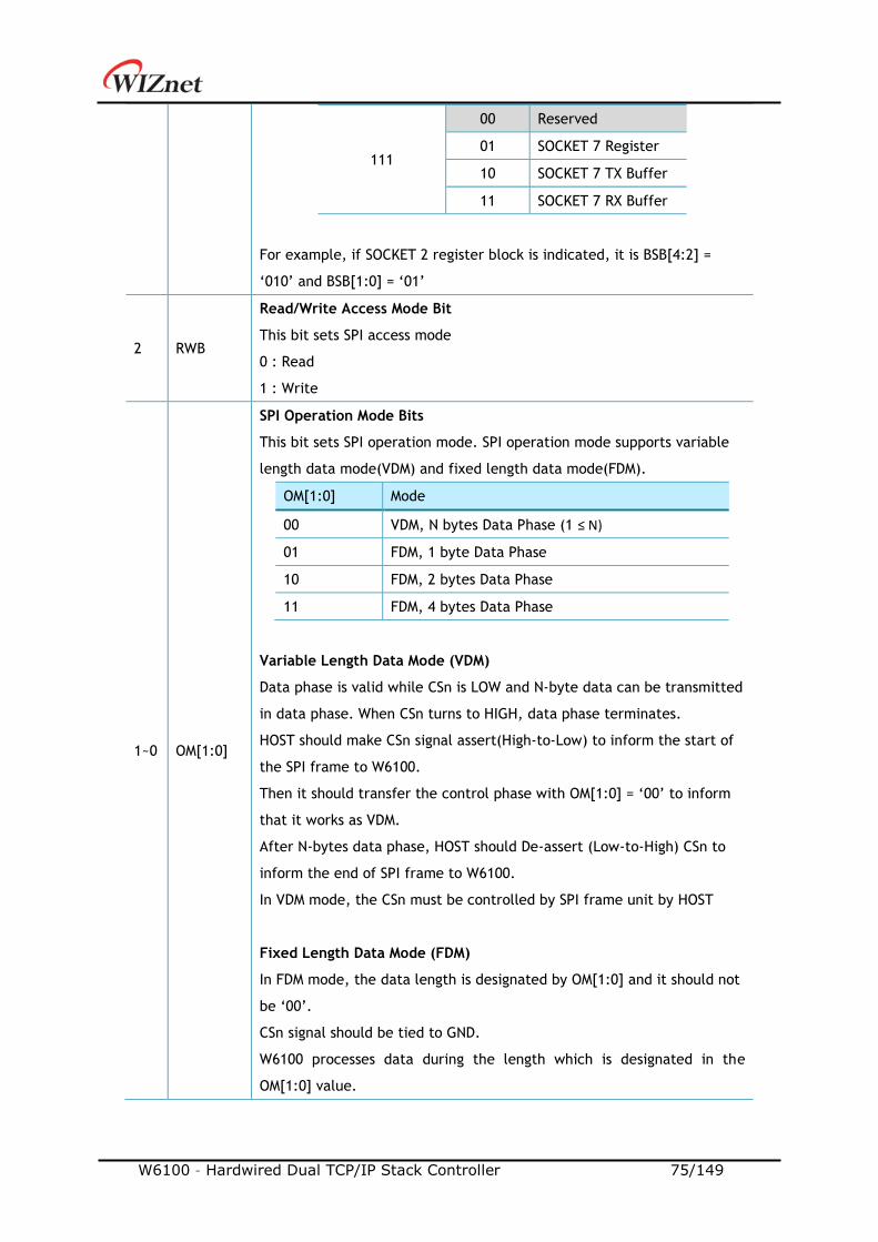
W6100 – Hardwired Dual TCP/IP Stack Controller 75/149
111
00 Reserved
01 SOCKET 7 Register
10 SOCKET 7 TX Buffer
11 SOCKET 7 RX Buffer
For example, if SOCKET 2 register block is indicated, it is BSB[4:2] =
‘010’ and BSB[1:0] = ‘01’
2 RWB
Read/Write Access Mode Bit
This bit sets SPI access mode
0 : Read
1 : Write
1~0 OM[1:0]
SPI Operation Mode Bits
This bit sets SPI operation mode. SPI operation mode supports variable
length data mode(VDM) and fixed length data mode(FDM).
OM[1:0] Mode
00 VDM, N bytes Data Phase (1 ≤ N)
01 FDM, 1 byte Data Phase
10 FDM, 2 bytes Data Phase
11 FDM, 4 bytes Data Phase
Variable Length Data Mode (VDM)
Data phase is valid while CSn is LOW and N-byte data can be transmitted
in data phase. When CSn turns to HIGH, data phase terminates.
HOST should make CSn signal assert(High-to-Low) to inform the start of
the SPI frame to W6100.
Then it should transfer the control phase with OM[1:0] = ‘00’ to inform
that it works as VDM.
After N-bytes data phase, HOST should De-assert (Low-to-High) CSn to
inform the end of SPI frame to W6100.
In VDM mode, the CSn must be controlled by SPI frame unit by HOST
Fixed Length Data Mode (FDM)
In FDM mode, the data length is designated by OM[1:0] and it should not
be ‘00’.
CSn signal should be tied to GND.
W6100 processes data during the length which is designated in the
OM[1:0] value.
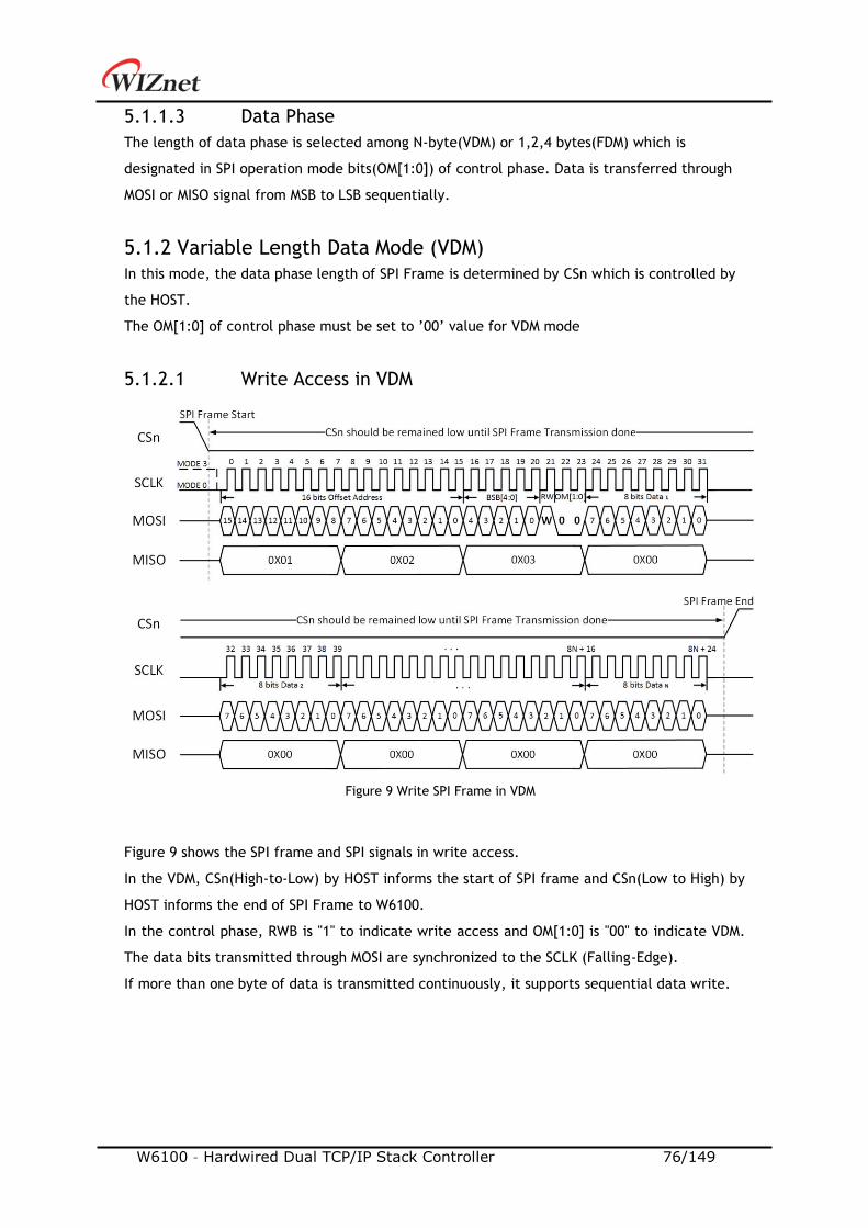
W6100 – Hardwired Dual TCP/IP Stack Controller 76/149
5.1.1.3 Data Phase
The length of data phase is selected among N-byte(VDM) or 1,2,4 bytes(FDM) which is
designated in SPI operation mode bits(OM[1:0]) of control phase. Data is transferred through
MOSI or MISO signal from MSB to LSB sequentially.
5.1.2 Variable Length Data Mode (VDM)
In this mode, the data phase length of SPI Frame is determined by CSn which is controlled by
the HOST.
The OM[1:0] of control phase must be set to ’00’ value for VDM mode
5.1.2.1 Write Access in VDM
Figure 9 shows the SPI frame and SPI signals in write access.
In the VDM, CSn(High-to-Low) by HOST informs the start of SPI frame and CSn(Low to High) by
HOST informs the end of SPI Frame to W6100.
In the control phase, RWB is "1" to indicate write access and OM[1:0] is "00" to indicate VDM.
The data bits transmitted through MOSI are synchronized to the SCLK (Falling-Edge).
If more than one byte of data is transmitted continuously, it supports sequential data write.
Figure 9 Write SPI Frame in VDM
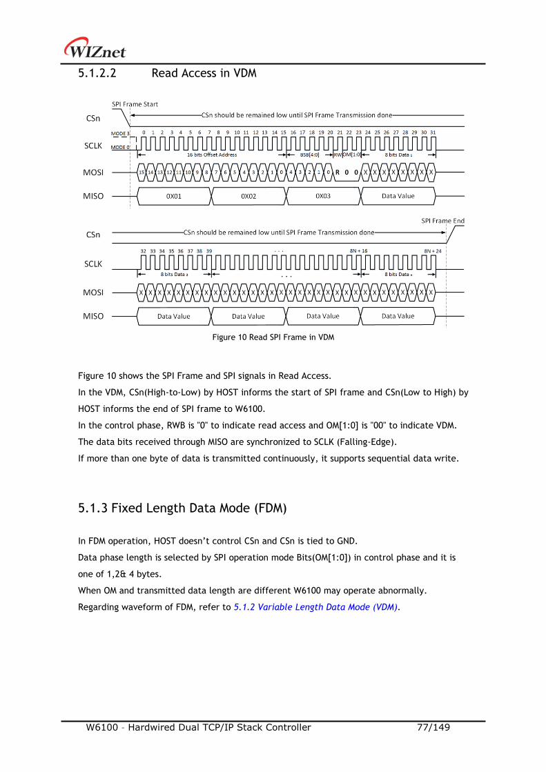
W6100 – Hardwired Dual TCP/IP Stack Controller 77/149
5.1.2.2 Read Access in VDM
Figure 10 Read SPI Frame in VDM
Figure 10 shows the SPI Frame and SPI signals in Read Access.
In the VDM, CSn(High-to-Low) by HOST informs the start of SPI frame and CSn(Low to High) by
HOST informs the end of SPI frame to W6100.
In the control phase, RWB is "0" to indicate read access and OM[1:0] is "00" to indicate VDM.
The data bits received through MISO are synchronized to SCLK (Falling-Edge).
If more than one byte of data is transmitted continuously, it supports sequential data write.
5.1.3 Fixed Length Data Mode (FDM)
In FDM operation, HOST doesn’t control CSn and CSn is tied to GND.
Data phase length is selected by SPI operation mode Bits(OM[1:0]) in control phase and it is
one of 1,2& 4 bytes.
When OM and transmitted data length are different W6100 may operate abnormally.
Regarding waveform of FDM, refer to 5.1.2 Variable Length Data Mode (VDM).
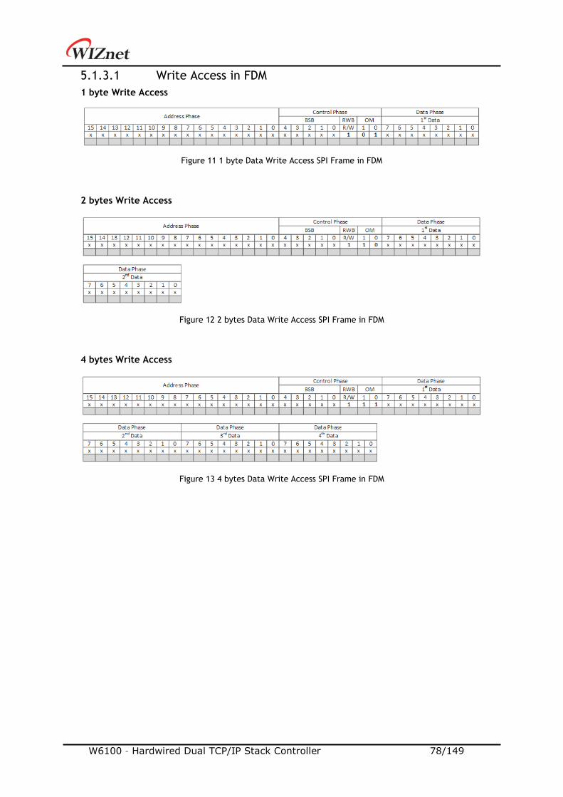
W6100 – Hardwired Dual TCP/IP Stack Controller 78/149
5.1.3.1 Write Access in FDM
1 byte Write Access
Figure 11 1 byte Data Write Access SPI Frame in FDM
2 bytes Write Access
Figure 12 2 bytes Data Write Access SPI Frame in FDM
4 bytes Write Access
Figure 13 4 bytes Data Write Access SPI Frame in FDM

W6100 – Hardwired Dual TCP/IP Stack Controller 79/149
5.1.3.2 Read Access in FDM
1 byte Read Access
Figure 14 1byte Data Read Access SPI Frame in FDM
2 bytes Read Access
Figure 15 2 bytes Data Read Access SPI Frame in FDM
4 bytes Read Access
Figure 16 4 bytes Data Read Access SPI Frame in FDM
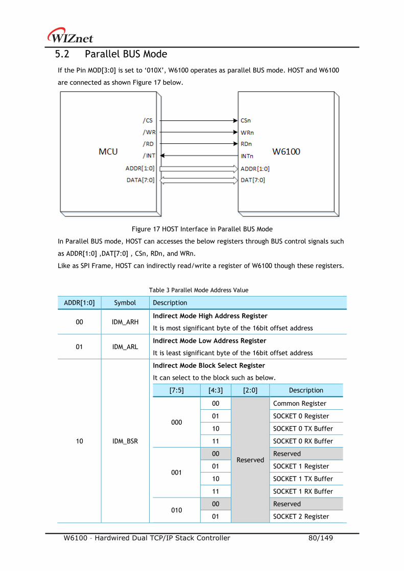
W6100 – Hardwired Dual TCP/IP Stack Controller 80/149
5.2 Parallel BUS Mode
If the Pin MOD[3:0] is set to ‘010X’, W6100 operates as parallel BUS mode. HOST and W6100
are connected as shown Figure 17 below.
Figure 17 HOST Interface in Parallel BUS Mode
In Parallel BUS mode, HOST can accesses the below registers through BUS control signals such
as ADDR[1:0] ,DAT[7:0] , CSn, RDn, and WRn.
Like as SPI Frame, HOST can indirectly read/write a register of W6100 though these registers.
Table 3 Parallel Mode Address Value
ADDR[1:0] Symbol Description
00 IDM_ARH Indirect Mode High Address Register
It is most significant byte of the 16bit offset address
01 IDM_ARL Indirect Mode Low Address Register
It is least significant byte of the 16bit offset address
10 IDM_BSR
Indirect Mode Block Select Register
It can select to the block such as below.
[7:5] [4:3] [2:0] Description
000
00
Reserved
Common Register
01 SOCKET 0 Register
10 SOCKET 0 TX Buffer
11 SOCKET 0 RX Buffer
001
00 Reserved
01 SOCKET 1 Register
10 SOCKET 1 TX Buffer
11 SOCKET 1 RX Buffer
010 00 Reserved
01 SOCKET 2 Register
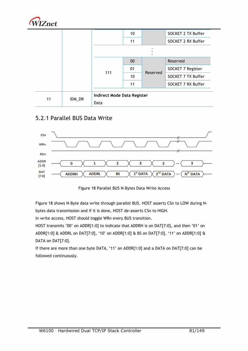
W6100 – Hardwired Dual TCP/IP Stack Controller 81/149
10 SOCKET 2 TX Buffer
11 SOCKET 2 RX Buffer
.
.
.
111
00
Reserved
Reserved
01 SOCKET 7 Register
10 SOCKET 7 TX Buffer
11 SOCKET 7 RX Buffer
11 IDM_DR Indirect Mode Data Register
Data
5.2.1 Parallel BUS Data Write
Figure 18 Parallel BUS N-Bytes Data Write Access
Figure 18 shows N-Byte data write through parallel BUS. HOST asserts CSn to LOW during N-
bytes data transmission and if it is done, HOST de-asserts CSn to HIGH.
In write access, HOST should toggle WRn every BUS transition.
HOST transmits ‘00’ on ADDR[1:0] to indicate that ADDRH is on DAT[7:0], and then ‘01’ on
ADDR[1:0] & ADDRL on DAT[7:0], ‘10’ on ADDR[1:0] & BS on DAT[7:0], ‘11’ on ADDR[1:0] &
DATA on DAT[7:0].
If there are more than one byte DATA, ‘11’ on ADDR[1:0] and a DATA on DAT[7:0] can be
followed continuously.

W6100 – Hardwired Dual TCP/IP Stack Controller 82/149
5.2.2 Parallel BUS Data Read
Figure 19 Parallel Mode Continuous Read Access
Figure 19 shows N-Byte data read through parallel BUS. HOST asserts CSn to LOW during N-
bytes data read and if it is done, HOST de-asserts CSn to HIGH.
In read access, HOST should toggle WRn for controlling BUS and toggle RDn for reading DATA,
every BUS transition.
HOST transmits ‘00’ on ADDR[1:0] to indicate that ADDRH is on DAT[7:0], and then ‘01’ on
ADDR[1:0] & ADDRL on DAT[7:0], ‘10’ on ADDR[1:0] & BS on DAT[7:0].
After transmitting three bytes, HOST transmits ‘11’ on ADDR[1:0] to read DATA on DAT[7:0].
If there are more than one byte DATA to read, HOST can transmit continuously ‘11’ on
ADDR[1:0], and reads a DATA on DAT[7:0].
W6100 – Hardwired Dual TCP/IP Stack Controller 83/149
6. Functional Description
W6100 can process internet connectivity by simply manipulating some registers. This section
shows how to set relative registers for W6100 initialization, using specific protocols like TCP,
UDP, IPRAW and MACRAW, and other functions.
6.1 Initialization
This shows the initialization of network information and TX/RX buffer memory.
6.1.1 Network Information Setting
It sets the basic network information for IPv4 or IPv6.
Network Configuration Unlock:
/* Network Unlock before set Network Information */
NETLCKR = 0x3A;
Source Hardware Address:
/* Source Hardware Address, 11:22:33:AA:BB:CC */
SHAR[0:5] = 0x11, 0x22, 0x33, 0xAA, 0xBB, 0xCC ;
IPv4 Network Information:
/* Gateway IP Address, 192.168.0.1 */
GAR[0:3] = 0xC0, 0xA8, 0x00, 0x01 ;
/* Subnet MASK Address, 255.255.255.0 */
SUBR[0:3] = 0xFF, 0xFF,, 0xFF, 0x00;
/* IP Address, 192.168.0.100 */
SIPR[0:3] = 0xC0, 0xA8,0x00, 0x64;
IPv6 Network Information:
/* Link Local Address, FE80::1322:33FF:FEAA:BBCC */
W6100 – Hardwired Dual TCP/IP Stack Controller 84/149
LLAR[0:15] = 0xFE, 0x80, 0x00, 0x01, 0x00, 0x00, 0x00, 0x00,
0x13, 0x22, 0x33, 0xFF, 0xFE, 0xAA, 0xBB, 0xCC ;
/* Global Unicast Address, 2001:0DB8:E001::1222:33FF:FEAA:BBCC */
GUAR[0:15] = 0x20, 0x01, 0x0D, 0xB8, 0xE0, 0x01, 0x00, 0x00,
0x13, 0x22, 0x33, 0xFF, 0xFE, 0xAA, 0xBB, 0xCC ;
/* IPv6 Subnet Mask Address, FFFF:FFFF:: */
SUB6R[0:15] = 0xFF, 0xFF, 0xFF, 0xFF, 0xFF, 0xFF, 0xFF, 0xFF
0x00, 0x00, 0x00, 0x00, 0x00, 0x00, 0x00, 0x00 ;
/* IPv6 Gateway Address, FE80::1322:33FF:FE44:5566 */
GA6R[0:15] = 0xFE, 0x80,0x00, 0x00, 0x00, 0x00, 0x00, 0x00,
0x13, 0x22, 0x33, 0xFF, 0xFE, 0x44, 0x55, 0x66 ;
Network Configuration Lock:
/* Network Lock before set Network Information */
NETLCKR = Any value except 0x3A;
6.1.2 SOCKET TX/RX Buffer Size Setting
Users need to define SOCKET n TX/RX buffer size by setting Sn_TX_BSR/Sn_RX_BSR before
SOCKET is opened.
SOCKET n TX/RX buffer size can be set to 0, 1, 2, 4, 8 or 16KB but the total size of TX or RX
buffer should not exceed 16KB each.
In case of, assign 2Kbytes RX/TX buffer per SOCKET
// set Base Address of TX/RX buffer for SOCKET n
TxTotalSize = 0; // for check the total size of SOCKET n TX Buffer
RxTotalSize = 0; // for check the total size of SOCKET n RX Buffer
for (n=0; n<7; n++)
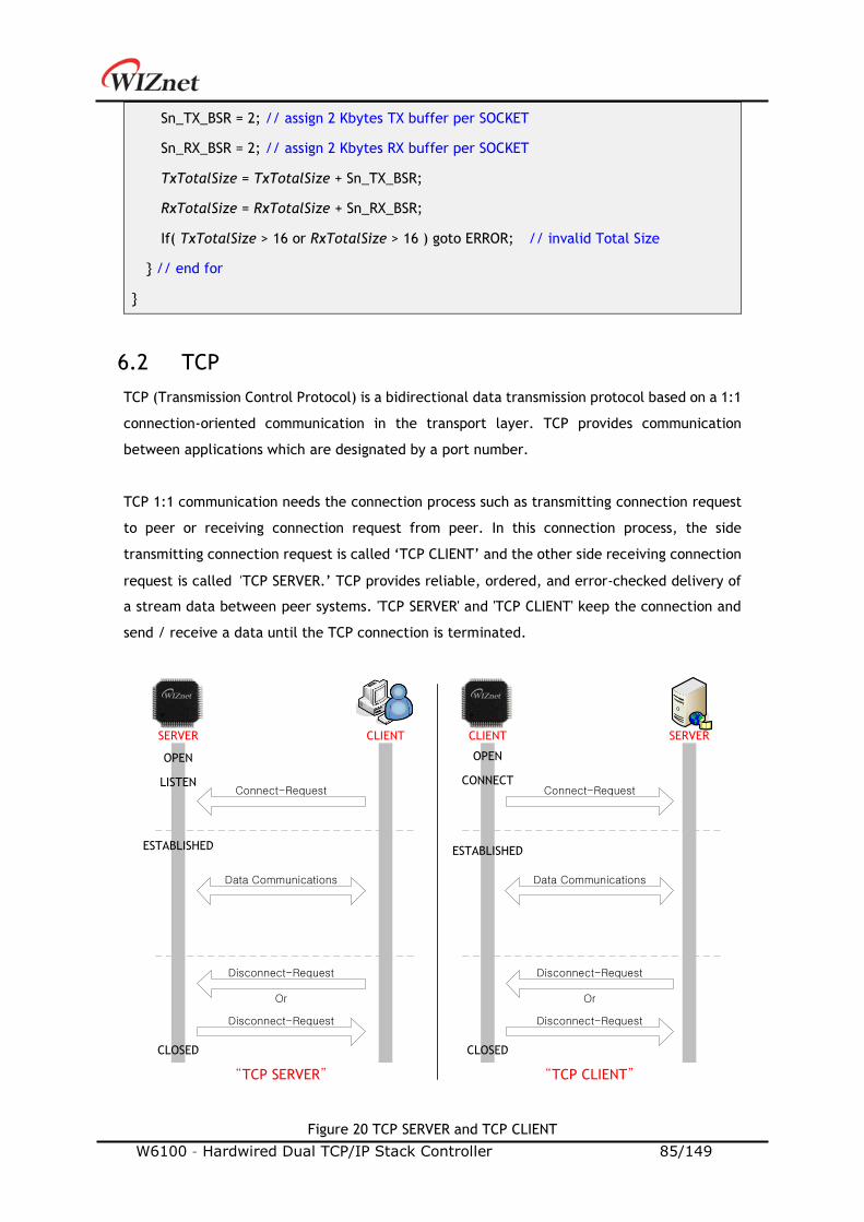
W6100 – Hardwired Dual TCP/IP Stack Controller 85/149
Sn_TX_BSR = 2; // assign 2 Kbytes TX buffer per SOCKET
Sn_RX_BSR = 2; // assign 2 Kbytes RX buffer per SOCKET
TxTotalSize = TxTotalSize + Sn_TX_BSR;
RxTotalSize = RxTotalSize + Sn_RX_BSR;
If( TxTotalSize > 16 or RxTotalSize > 16 ) goto ERROR; // invalid Total Size
// end for
6.2 TCP
TCP (Transmission Control Protocol) is a bidirectional data transmission protocol based on a 1:1
connection-oriented communication in the transport layer. TCP provides communication
between applications which are designated by a port number.
TCP 1:1 communication needs the connection process such as transmitting connection request
to peer or receiving connection request from peer. In this connection process, the side
transmitting connection request is called ‘TCP CLIENT’ and the other side receiving connection
request is called ‘TCP SERVER.’ TCP provides reliable, ordered, and error-checked delivery of
a stream data between peer systems. 'TCP SERVER' and 'TCP CLIENT' keep the connection and
send / receive a data until the TCP connection is terminated.
Figure 20 TCP SERVER and TCP CLIENT
SERVER CLIENT SERVERCLIENT
“TCP SERVER” “TCP CLIENT”
OPEN
LISTEN
ESTABLISHED
CLOSED
OPEN
CONNECT
ESTABLISHED
CLOSED
Connect-Request
Data Communications
Disconnect-Request
Or
Disconnect-Request
Or
Disconnect-Request
Disconnect-Request
Data Communications
Connect-Request
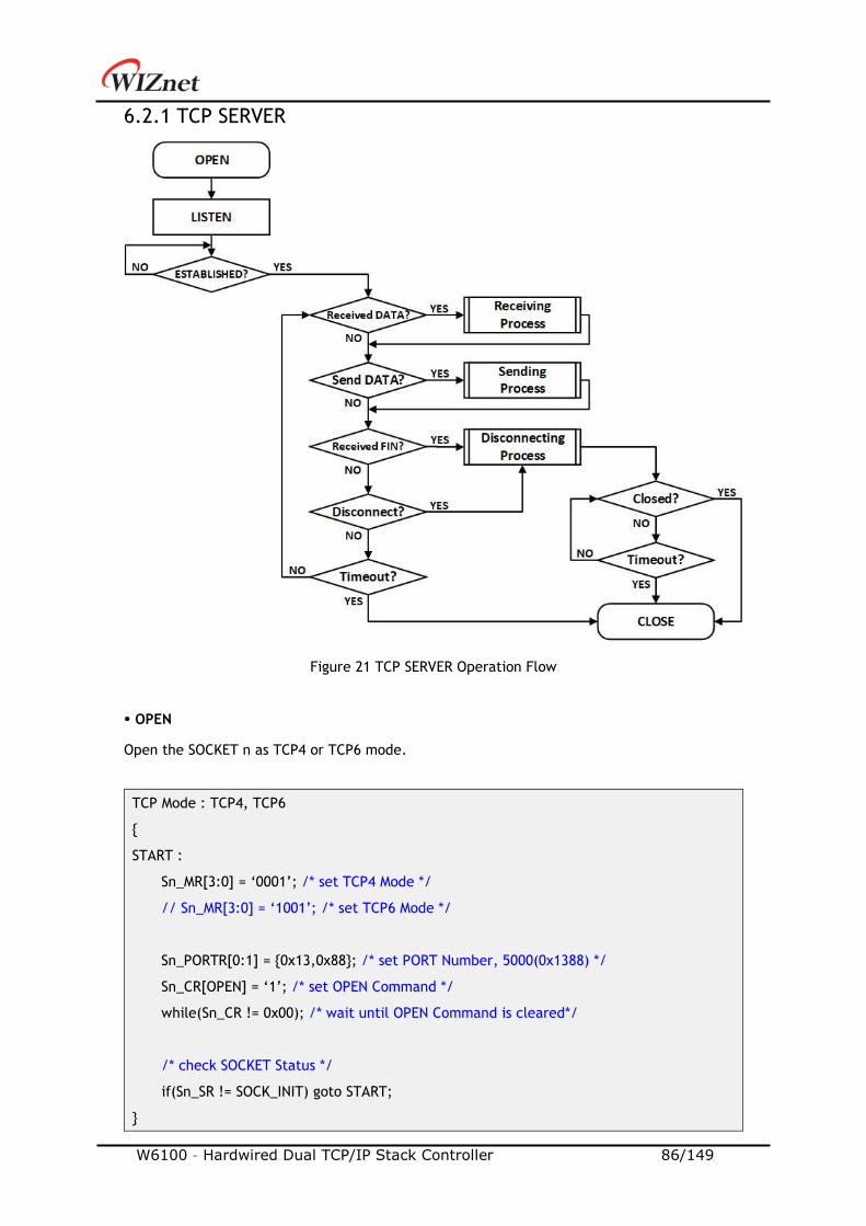
W6100 – Hardwired Dual TCP/IP Stack Controller 86/149
6.2.1 TCP SERVER
Figure 21 TCP SERVER Operation Flow
OPEN
Open the SOCKET n as TCP4 or TCP6 mode.
TCP Mode : TCP4, TCP6
START :
Sn_MR[3:0] = ‘0001’; /* set TCP4 Mode */
// Sn_MR[3:0] = ‘1001’; /* set TCP6 Mode */
Sn_PORTR[0:1] = 0x13,0x88; /* set PORT Number, 5000(0x1388) */
Sn_CR[OPEN] = ‘1’; /* set OPEN Command */
while(Sn_CR != 0x00); /* wait until OPEN Command is cleared*/
/* check SOCKET Status */
if(Sn_SR != SOCK_INIT) goto START;

W6100 – Hardwired Dual TCP/IP Stack Controller 87/149
LISTEN
SOCKET n is listening as ‘TCP SERVER’ by Sn_CR [LISTEN] command. Users can check it by
reading Sn_SR (SOCK_LISTEN).
Sn_CR = LISTEN; /* set LISTEN Command */
while(Sn_CR != 0x00); /* wait until LISTEN Command is cleared*/
if(Sn_SR != SOCK_LISTEN) goto OPEN; /* check SOCKET Status */
ESTABLISHED?
‘TCP SERVER’ remains LISTEN status (Sn_SR=SOCK_LISTEN) until receiving SYN Packet. If ‘TCP
SERVER’ receives SYN packet from ‘TCP CLIENT’, it transmits SYN/ACK packet to ‘TCP CLIENT’
and the connection between ‘TCP SERVER’ and ‘TCP CLIENT’ is established if it receives ACK
packet.
When the connection is established, Sn_IR[CON] interrupt occurs and Sn_SR value is changed
to SOCK_ESTABLISHED. And users can read the destination address from the Sn_DIPR or
Sn_DIP6R register.
First method :
/* check SOCKET Interrupt */
if(Sn_IR[CON] == ‘1’)
Sn_IRCLR[CON] = ‘1’; /* clear SOCKET Interrupt */
goto Received DATA?; /* or goto Send DATA?; */
// end if
else if(Sn_IR[TIMEOUT] == ‘1’) goto Timeout?;
/* check destination address */
if(Sn_MR[3:0] == TCP6 Mode)
destination_addr[0:15] = Sn_DIP6R;
else if(Sn_MR[3:0] == TCP4 Mode)
destination_addr[0:3] = Sn_DIPR;
Second method :
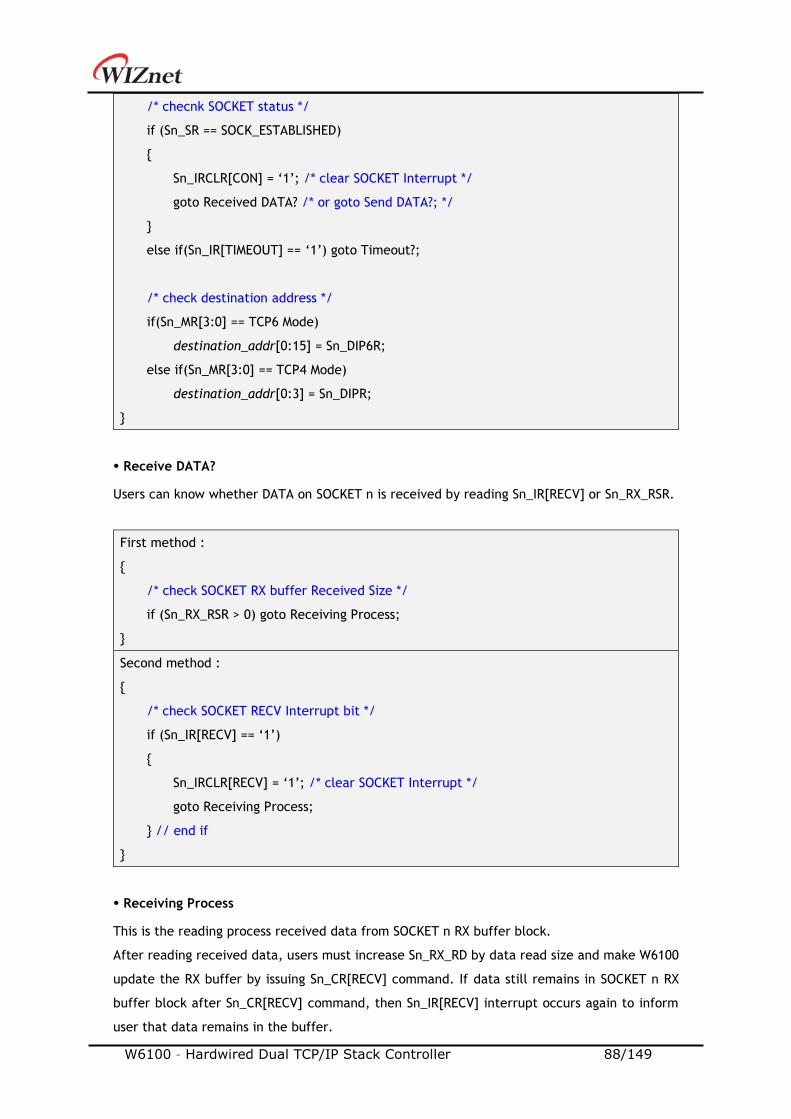
W6100 – Hardwired Dual TCP/IP Stack Controller 88/149
/* checnk SOCKET status */
if (Sn_SR == SOCK_ESTABLISHED)
Sn_IRCLR[CON] = ‘1’; /* clear SOCKET Interrupt */
goto Received DATA? /* or goto Send DATA?; */
else if(Sn_IR[TIMEOUT] == ‘1’) goto Timeout?;
/* check destination address */
if(Sn_MR[3:0] == TCP6 Mode)
destination_addr[0:15] = Sn_DIP6R;
else if(Sn_MR[3:0] == TCP4 Mode)
destination_addr[0:3] = Sn_DIPR;
Receive DATA?
Users can know whether DATA on SOCKET n is received by reading Sn_IR[RECV] or Sn_RX_RSR.
First method :
/* check SOCKET RX buffer Received Size */
if (Sn_RX_RSR > 0) goto Receiving Process;
Second method :
/* check SOCKET RECV Interrupt bit */
if (Sn_IR[RECV] == ‘1’)
Sn_IRCLR[RECV] = ‘1’; /* clear SOCKET Interrupt */
goto Receiving Process;
// end if
Receiving Process
This is the reading process received data from SOCKET n RX buffer block.
After reading received data, users must increase Sn_RX_RD by data read size and make W6100
update the RX buffer by issuing Sn_CR[RECV] command. If data still remains in SOCKET n RX
buffer block after Sn_CR[RECV] command, then Sn_IR[RECV] interrupt occurs again to inform
user that data remains in the buffer.
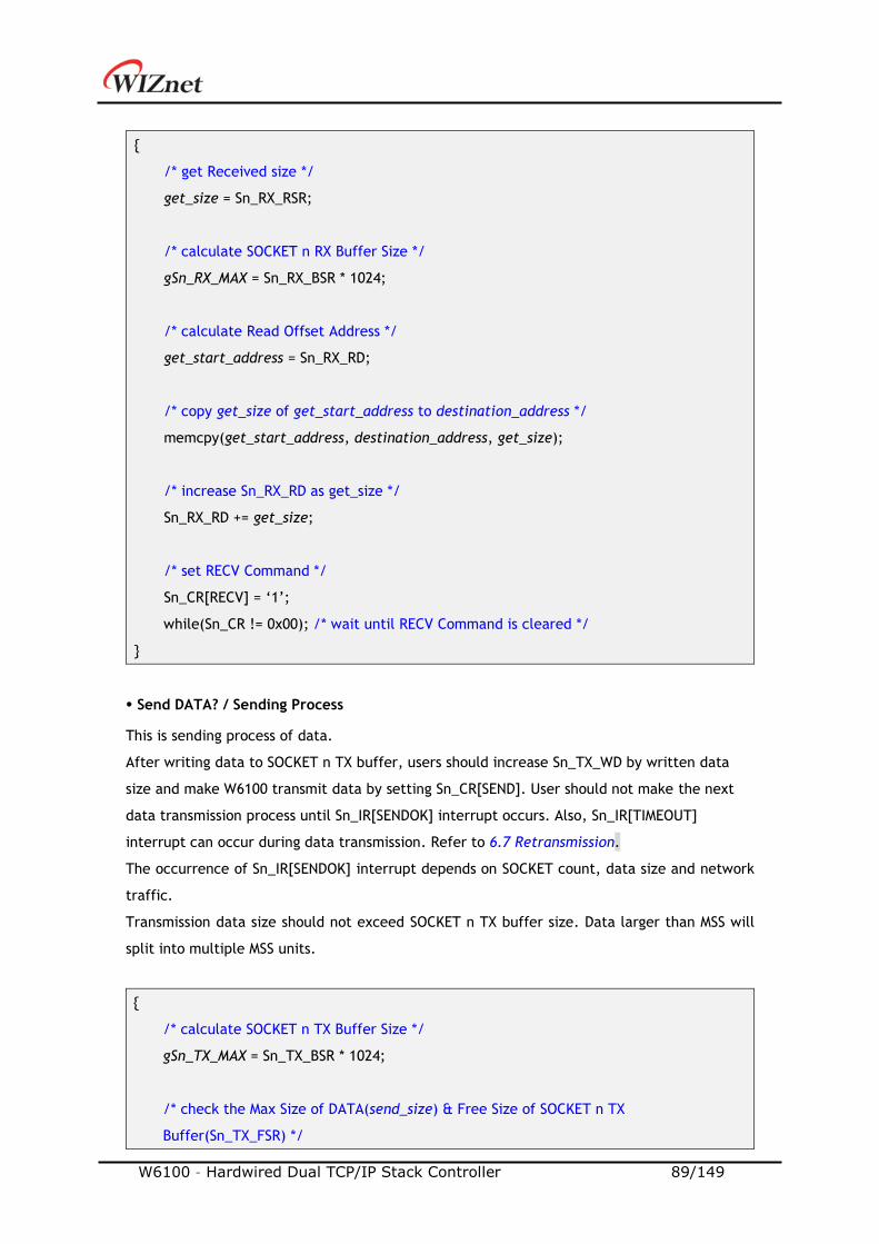
W6100 – Hardwired Dual TCP/IP Stack Controller 89/149
/* get Received size */
get_size = Sn_RX_RSR;
/* calculate SOCKET n RX Buffer Size */
gSn_RX_MAX = Sn_RX_BSR * 1024;
/* calculate Read Offset Address */
get_start_address = Sn_RX_RD;
/* copy get_size of get_start_address to destination_address */
memcpy(get_start_address, destination_address, get_size);
/* increase Sn_RX_RD as get_size */
Sn_RX_RD += get_size;
/* set RECV Command */
Sn_CR[RECV] = ‘1’;
while(Sn_CR != 0x00); /* wait until RECV Command is cleared */
Send DATA? / Sending Process
This is sending process of data.
After writing data to SOCKET n TX buffer, users should increase Sn_TX_WD by written data
size and make W6100 transmit data by setting Sn_CR[SEND]. User should not make the next
data transmission process until Sn_IR[SENDOK] interrupt occurs. Also, Sn_IR[TIMEOUT]
interrupt can occur during data transmission. Refer to 6.7 Retransmission.
The occurrence of Sn_IR[SENDOK] interrupt depends on SOCKET count, data size and network
traffic.
Transmission data size should not exceed SOCKET n TX buffer size. Data larger than MSS will
split into multiple MSS units.
/* calculate SOCKET n TX Buffer Size */
gSn_TX_MAX = Sn_TX_BSR * 1024;
/* check the Max Size of DATA(send_size) & Free Size of SOCKET n TX
Buffer(Sn_TX_FSR) */
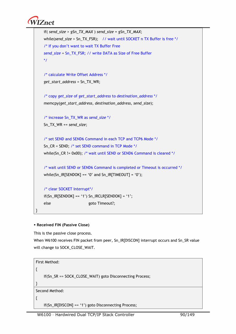
W6100 – Hardwired Dual TCP/IP Stack Controller 90/149
if( send_size > gSn_TX_MAX ) send_size = gSn_TX_MAX;
while(send_size > Sn_TX_FSR); // wait until SOCKET n TX Buffer is free */
/* If you don’t want to wait TX Buffer Free
send_size = Sn_TX_FSR; // write DATA as Size of Free Buffer
*/
/* calculate Write Offset Address */
get_start_address = Sn_TX_WR;
/* copy get_size of get_start_address to destination_address */
memcpy(get_start_address, destination_address, send_size);
/* increase Sn_TX_WR as send_size */
Sn_TX_WR += send_size;
/* set SEND and SEND6 Command in each TCP and TCP6 Mode */
Sn_CR = SEND; /* set SEND command in TCP Mode */
while(Sn_CR != 0x00); /* wait until SEND or SEND6 Command is cleared */
/* wait until SEND or SEND6 Command is completed or Timeout is occurred */
while(Sn_IR[SENDOK] == ‘0’ and Sn_IR[TIMEOUT] = ‘0’);
/* clear SOCKET Interrupt*/
if(Sn_IR[SENDOK] == ‘1’) Sn_IRCLR[SENDOK] = ‘1’;
else goto Timeout?;
Received FIN (Passive Close)
This is the passive close process.
When W6100 receives FIN packet from peer, Sn_IR[DISCON] interrupt occurs and Sn_SR value
will change to SOCK_CLOSE_WAIT.
First Method:
If(Sn_SR == SOCK_CLOSE_WAIT) goto Disconnecting Process;
Second Method:
If(Sn_IR[DISCON] == ‘1’) goto Disconnecting Process;
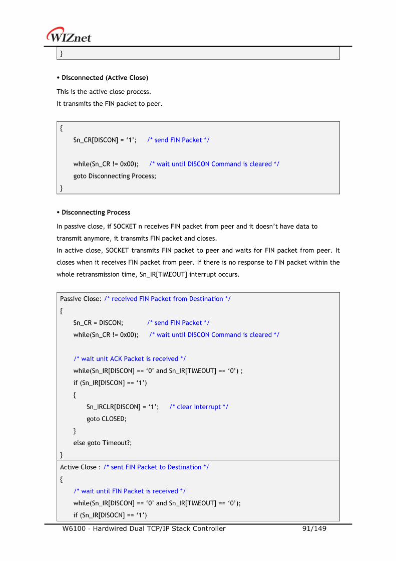
W6100 – Hardwired Dual TCP/IP Stack Controller 91/149
Disconnected (Active Close)
This is the active close process.
It transmits the FIN packet to peer.
Sn_CR[DISCON] = ‘1’; /* send FIN Packet */
while(Sn_CR != 0x00); /* wait until DISCON Command is cleared */
goto Disconnecting Process;
Disconnecting Process
In passive close, if SOCKET n receives FIN packet from peer and it doesn’t have data to
transmit anymore, it transmits FIN packet and closes.
In active close, SOCKET transmits FIN packet to peer and waits for FIN packet from peer. It
closes when it receives FIN packet from peer. If there is no response to FIN packet within the
whole retransmission time, Sn_IR[TIMEOUT] interrupt occurs.
Passive Close: /* received FIN Packet from Destination */
Sn_CR = DISCON; /* send FIN Packet */
while(Sn_CR != 0x00); /* wait until DISCON Command is cleared */
/* wait unit ACK Packet is received */
while(Sn_IR[DISCON] == ‘0’ and Sn_IR[TIMEOUT] == ‘0’) ;
if (Sn_IR[DISCON] == ‘1’)
Sn_IRCLR[DISCON] = ‘1’; /* clear Interrupt */
goto CLOSED;
else goto Timeout?;
Active Close : /* sent FIN Packet to Destination */
/* wait until FIN Packet is received */
while(Sn_IR[DISCON] == ‘0’ and Sn_IR[TIMEOUT] == ‘0’);
if (Sn_IR[DISOCN] == ‘1’)
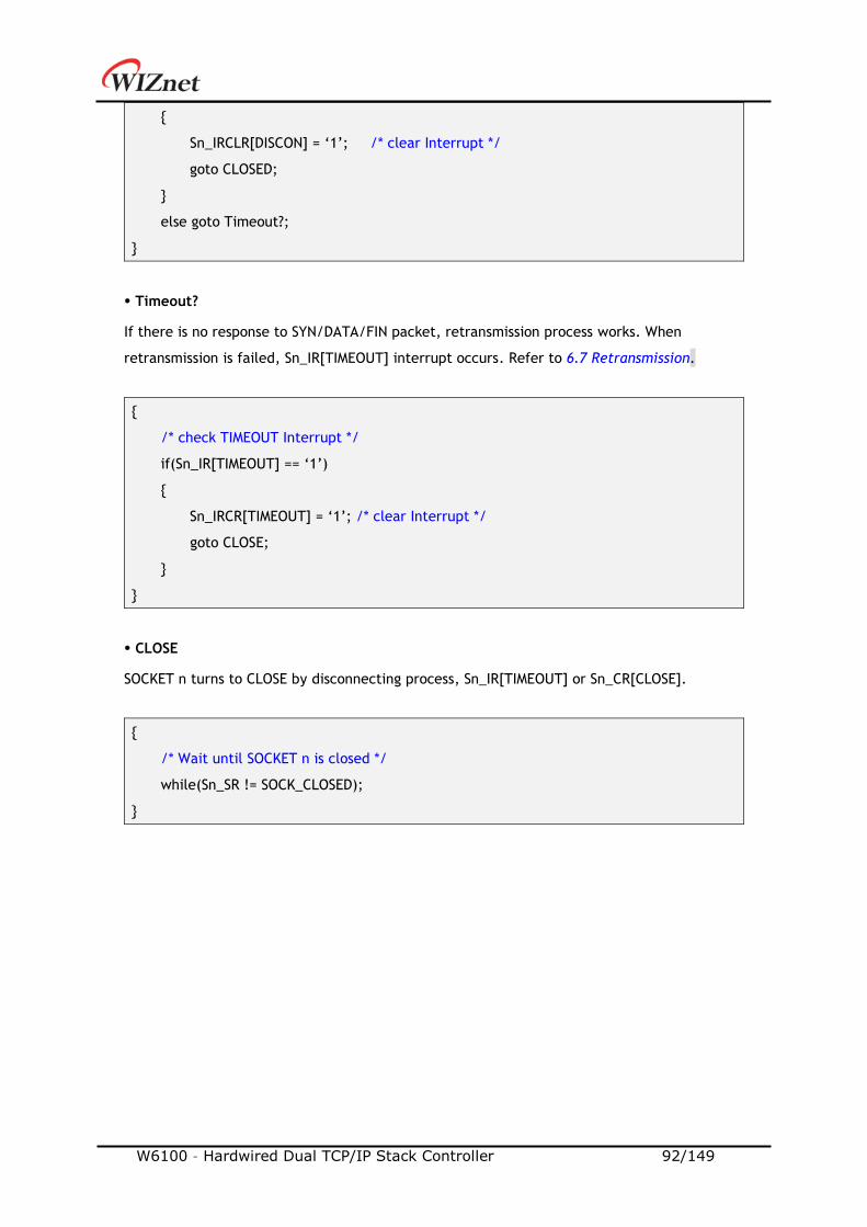
W6100 – Hardwired Dual TCP/IP Stack Controller 92/149
Sn_IRCLR[DISCON] = ‘1’; /* clear Interrupt */
goto CLOSED;
else goto Timeout?;
Timeout?
If there is no response to SYN/DATA/FIN packet, retransmission process works. When
retransmission is failed, Sn_IR[TIMEOUT] interrupt occurs. Refer to 6.7 Retransmission.
/* check TIMEOUT Interrupt */
if(Sn_IR[TIMEOUT] == ‘1’)
Sn_IRCR[TIMEOUT] = ‘1’; /* clear Interrupt */
goto CLOSE;
CLOSE
SOCKET n turns to CLOSE by disconnecting process, Sn_IR[TIMEOUT] or Sn_CR[CLOSE].
/* Wait until SOCKET n is closed */
while(Sn_SR != SOCK_CLOSED);
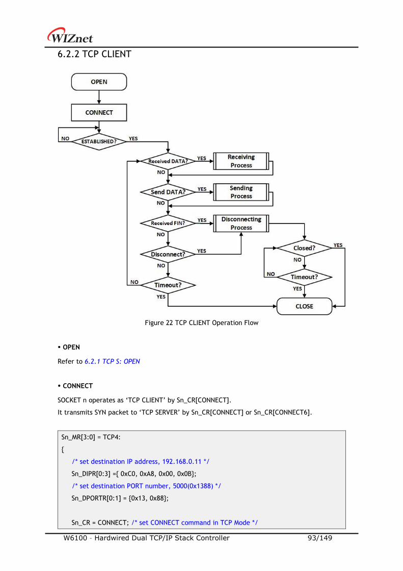
W6100 – Hardwired Dual TCP/IP Stack Controller 93/149
6.2.2 TCP CLIENT
Figure 22 TCP CLIENT Operation Flow
OPEN
Refer to 6.2.1 TCP S: OPEN
CONNECT
SOCKET n operates as ‘TCP CLIENT’ by Sn_CR[CONNECT].
It transmits SYN packet to ‘TCP SERVER’ by Sn_CR[CONNECT] or Sn_CR[CONNECT6].
Sn_MR[3:0] = TCP4:
/* set destination IP address, 192.168.0.11 */
Sn_DIPR[0:3] = 0xC0, 0xA8, 0x00, 0x0B;
/* set destination PORT number, 5000(0x1388) */
Sn_DPORTR[0:1] = 0x13, 0x88;
Sn_CR = CONNECT; /* set CONNECT command in TCP Mode */
W6100 – Hardwired Dual TCP/IP Stack Controller 94/149
while(Sn_CR != 0x00); /* wait until CONNECT or CONNECT6 command is cleared */
goto ESTABLISHED?;
Sn_MR[3:0] = TCP6:
/* set destination IP address, FE80::10D:FC:34A:EF90 */
Sn_DIP6R[0:15] = 0xFE, 0x80, 0x00, 0x00, 0x00, 0x00, 0x00, 0x00
0x01, 0x0D, 0x00, 0xFC, 0x03, 0x4A, 0xEF, 0x90;
/* set destination PORT number, 5000(0x1388) */
Sn_PORTR[0:1] = 0x13, 0x88;
Sn_CR = CONNECT6; /* set CONNECT6 command in TCP6 Mode */
while(Sn_CR != 0x00); /* wait until CONNECT or CONNECT6 command is cleared */
goto ESTABLISHED?;
ESTABLISHED?
After transmitting SYN packet, ‘TCP CLIENT’ maintains status SOCK_SYNSENT until receiving
SYN/ACK packet from ‘TCP SERVER’. When receiving SYN/ACK packet which is transferred from
‘TCP SERVER’, the connection process between ‘TCP SERVER’ and ‘TCP CLIENT’ is completed.
If the connection is completed, Sn_IR[CON] interrupt occurs and Sn_SR is changed to
SOCK_ESTABLISHED. Users can know the destination address through the Sn_DIPR or Sn_DIP6R
register.
Refer to 6.2.1 TCP SERVER : ESTABLISHED?
Others flow
Refer to 6.2.1 TCP SERVER : ESTABLISHED?
6.2.3 TCP DUAL
SOCKET provides TCP Dual (TCPD) mode based on IP version 4 or 6.
When the SOCKET that is opened in TCPD Mode operates as 'TCP DUAL SERVER' by Sn_CR [LISTEN],
whether it works as TCP4 or TCP6 is determined according to the IP version of connected
destination.
When operating as 'TCP DUAL CLIENT', whether it operates as TCP4 or TCP6 is determined by
Sn_CR[CONNECT] or Sn_CR[CONNECT6].
When the connection is established, the HOST can know whether the SOCKET operates as TCP4
or TCP6 through checking Sn_ESR[TCPM].

W6100 – Hardwired Dual TCP/IP Stack Controller 95/149
6.2.3.1 TCP DUAL SERVER
‘TCP DUAL SERVER’ operation flow is same to Figure 21.
OPEN
Open SOCKET n as TCPD mode.
TCP Mode : TCP4, TCP6, TCPD
START :
Sn_MR[3:0] = ‘1101’; /* set TCPD Mode */
Sn_PORTR[0:1] = 0x13,0x88; /* set PORT Number, 5000(0x1388) */
Sn_CR[OPEN] = ‘1’; /* set OPEN Command */
while(Sn_CR != 0x00); /* wait until OPEN Command is cleared */
/* check SOCKET Status */
if(Sn_SR != SOCK_INIT) goto START;
Others flow
Refer to 6.2.1 TCP SERVER
6.2.3.2 TCP DUAL CLIENT
‘TCP DUAL CLIENT’ operation flow is same to Figure 22.
OPEN
Refer to 6.2.3.1 TCP DUAL SERVER : OPEN
CONNECT
By Sn_CR[CONNECT] or Sn_CR[CONNECT6], SOCKET n sends SYN packet to destination.
TCP4 :
/* set destination IP address, 192.168.0.11 */
Sn_DIPR[0:3] = 0xC0, 0xA8, 0x00, 0x0B;
/* set destination PORT number, 5000(0x1388) */
Sn_DPORTR[0:1] = 0x13, 0x88;
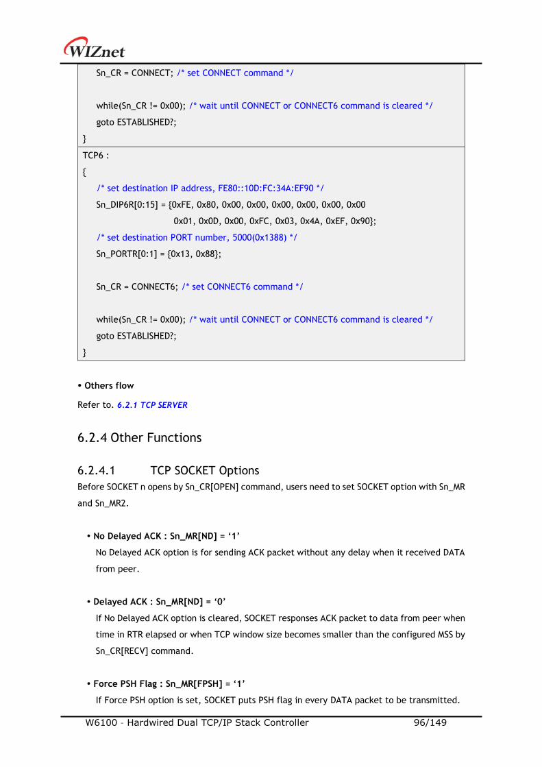
W6100 – Hardwired Dual TCP/IP Stack Controller 96/149
Sn_CR = CONNECT; /* set CONNECT command */
while(Sn_CR != 0x00); /* wait until CONNECT or CONNECT6 command is cleared */
goto ESTABLISHED?;
TCP6 :
/* set destination IP address, FE80::10D:FC:34A:EF90 */
Sn_DIP6R[0:15] = 0xFE, 0x80, 0x00, 0x00, 0x00, 0x00, 0x00, 0x00
0x01, 0x0D, 0x00, 0xFC, 0x03, 0x4A, 0xEF, 0x90;
/* set destination PORT number, 5000(0x1388) */
Sn_PORTR[0:1] = 0x13, 0x88;
Sn_CR = CONNECT6; /* set CONNECT6 command */
while(Sn_CR != 0x00); /* wait until CONNECT or CONNECT6 command is cleared */
goto ESTABLISHED?;
Others flow
Refer to. 6.2.1 TCP SERVER
6.2.4 Other Functions
6.2.4.1 TCP SOCKET Options
Before SOCKET n opens by Sn_CR[OPEN] command, users need to set SOCKET option with Sn_MR
and Sn_MR2.
No Delayed ACK : Sn_MR[ND] = ‘1’
No Delayed ACK option is for sending ACK packet without any delay when it received DATA
from peer.
Delayed ACK : Sn_MR[ND] = ‘0’
If No Delayed ACK option is cleared, SOCKET responses ACK packet to data from peer when
time in RTR elapsed or when TCP window size becomes smaller than the configured MSS by
Sn_CR[RECV] command.
Force PSH Flag : Sn_MR[FPSH] = ‘1’
If Force PSH option is set, SOCKET puts PSH flag in every DATA packet to be transmitted.
W6100 – Hardwired Dual TCP/IP Stack Controller 97/149
Auto PSH Flag : Sn_MR[FPSH] = ‘0’
If Force PSH option is cleared, SOCKET places the PSH flag in the last DATA packet sent by
Sn_CR[SEND].
Destination Hardware Address by Sn_DHAR : Sn_MR2[DHAM] = ‘1’
If Sn_MR2[DHAM] is set, ARP/ND-process is skipped and Sn_DHAR is used as destination
hardware address.
Destination Hardware Address by ARP : Sn_MR2[DHAM] = ‘0’
In ‘TCP SERVER’ mode, destination hardware address is acquired from received SYN packet.
In ‘TCP CLIENT’ mode, destination hardware address is acquired from ARP/ND-process.
Destination Hardware Address by Sn_DHAR : Sn_MR2[FARP] = ‘1’
In 'TCP SERVER' mode, ARP process is performed before responding a SYN / ACK packet to
the SYN packet received from the "TCP client". And the address acquired from ARP/ND-
process is used as the destination hardware address.
If Sn_MR2 [DHAM] is also set, ARP/ND-process is performed but the Sn_DHAR is used as the
destination hardware address.
Destination Hardware Address Mode by ARP : Sn_MR2[FARP] = ‘0’
In ‘TCP SERVER’ mode, destination hardware address is acquired from received SYN packet.
In ‘TCP CLIENT’ mode, destination hardware address is acquired from ARP/ND-process.
6.2.4.2 Keep Alive
Keep Alive (KA) is to retransmit the last 1 byte of the already transmitted DATA packet to check
whether the connection is valid. Data size of 1 byte or more must be transmitted before using
Keep Alive function. If there is no response to KA packet within the whole retransmission time,
Sn_IR[TIMEOUT] interrupt occurs.
The period of KA packet transmission is set in Sn_KPALVTR. If Sn_KPALVTR is set to zero, KA
packet is able to be transmitted by Sn_CR[SEND_KEEP] command.
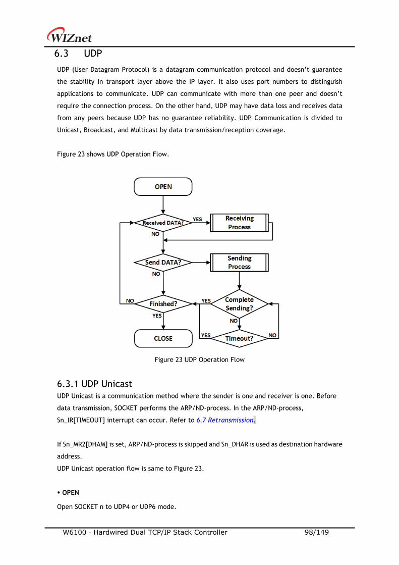
W6100 – Hardwired Dual TCP/IP Stack Controller 98/149
6.3 UDP
UDP (User Datagram Protocol) is a datagram communication protocol and doesn’t guarantee
the stability in transport layer above the IP layer. It also uses port numbers to distinguish
applications to communicate. UDP can communicate with more than one peer and doesn’t
require the connection process. On the other hand, UDP may have data loss and receives data
from any peers because UDP has no guarantee reliability. UDP Communication is divided to
Unicast, Broadcast, and Multicast by data transmission/reception coverage.
Figure 23 shows UDP Operation Flow.
Figure 23 UDP Operation Flow
6.3.1 UDP Unicast
UDP Unicast is a communication method where the sender is one and receiver is one. Before
data transmission, SOCKET performs the ARP/ND-process. In the ARP/ND-process,
Sn_IR[TIMEOUT] interrupt can occur. Refer to 6.7 Retransmission.
If Sn_MR2[DHAM] is set, ARP/ND-process is skipped and Sn_DHAR is used as destination hardware
address.
UDP Unicast operation flow is same to Figure 23.
OPEN
Open SOCKET n to UDP4 or UDP6 mode.
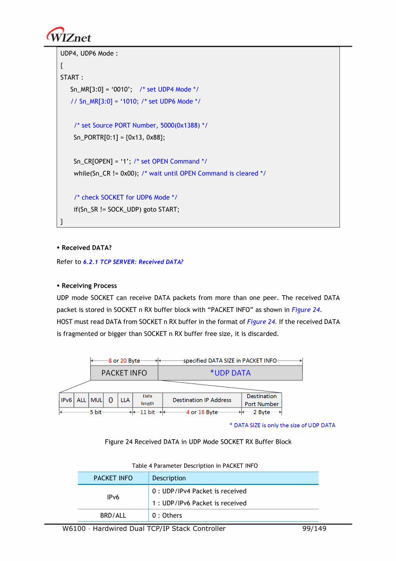
W6100 – Hardwired Dual TCP/IP Stack Controller 99/149
UDP4, UDP6 Mode :
START :
Sn_MR[3:0] = ‘0010’; /* set UDP4 Mode */
// Sn_MR[3:0] = ‘1010; /* set UDP6 Mode */
/* set Source PORT Number, 5000(0x1388) */
Sn_PORTR[0:1] = 0x13, 0x88;
Sn_CR[OPEN] = ‘1’; /* set OPEN Command */
while(Sn_CR != 0x00); /* wait until OPEN Command is cleared */
/* check SOCKET for UDP6 Mode */
if(Sn_SR != SOCK_UDP) goto START;
Received DATA?
Refer to 6.2.1 TCP SERVER: Received DATA?
Receiving Process
UDP mode SOCKET can receive DATA packets from more than one peer. The received DATA
packet is stored in SOCKET n RX buffer block with “PACKET INFO” as shown in Figure 24.
HOST must read DATA from SOCKET n RX buffer in the format of Figure 24. If the received DATA
is fragmented or bigger than SOCKET n RX buffer free size, it is discarded.
Figure 24 Received DATA in UDP Mode SOCKET RX Buffer Block
Table 4 Parameter Description in PACKET INFO
PACKET INFO Description
IPv6 0 : UDP/IPv4 Packet is received
1 : UDP/IPv6 Packet is received
BRD/ALL 0 : Others
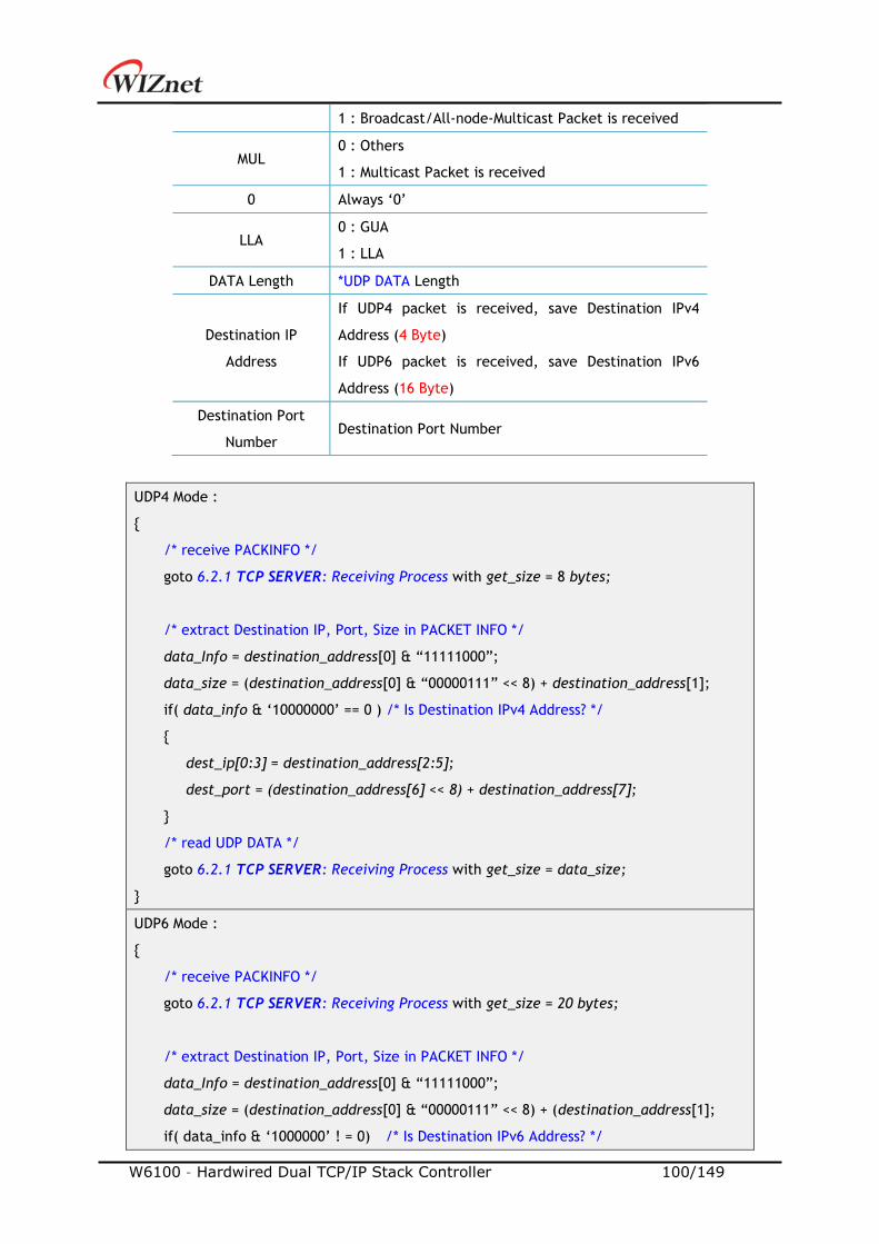
W6100 – Hardwired Dual TCP/IP Stack Controller 100/149
1 : Broadcast/All-node-Multicast Packet is received
MUL 0 : Others
1 : Multicast Packet is received
0 Always ‘0’
LLA 0 : GUA
1 : LLA
DATA Length *UDP DATA Length
Destination IP
Address
If UDP4 packet is received, save Destination IPv4
Address (4 Byte)
If UDP6 packet is received, save Destination IPv6
Address (16 Byte)
Destination Port
Number Destination Port Number
UDP4 Mode :
/* receive PACKINFO */
goto 6.2.1 TCP SERVER: Receiving Process with get_size = 8 bytes;
/* extract Destination IP, Port, Size in PACKET INFO */
data_Info = destination_address[0] & “11111000”;
data_size = (destination_address[0] & “00000111” << 8) + destination_address[1];
if( data_info & ‘10000000’ == 0 ) /* Is Destination IPv4 Address? */
dest_ip[0:3] = destination_address[2:5];
dest_port = (destination_address[6] << 8) + destination_address[7];
/* read UDP DATA */
goto 6.2.1 TCP SERVER: Receiving Process with get_size = data_size;
UDP6 Mode :
/* receive PACKINFO */
goto 6.2.1 TCP SERVER: Receiving Process with get_size = 20 bytes;
/* extract Destination IP, Port, Size in PACKET INFO */
data_Info = destination_address[0] & “11111000”;
data_size = (destination_address[0] & “00000111” << 8) + (destination_address[1];
if( data_info & ‘1000000’ ! = 0) /* Is Destination IPv6 Address? */

W6100 – Hardwired Dual TCP/IP Stack Controller 101/149
dest_ip[0:15] = destination_address[2:17];
dest_port = (destination_address[18] << 8) + destination_address[19];
/* read UDP DATA */
goto 6.2.1 TCP SERVER: Receiving Process with get_size = data_size;
Send DATA? / Sending Process
Refer to 6.2.1 TCP SERVER: Send DATA? / Sending Process
UDP4 Mode
/* set destination IP address, 192.168.0.11 */
Sn_DIPR[0:3] = 0xC0, 0xA8, 0x00, 0x0B;
/* set destination PORT number, 5000(0x1388) */
Sn_DPORTR[0:1] = 0x13, 0x88;
goto 6.2.1 TCP SERVER: Sending Process with Sn_CR[SEND];
UDP6 Mode
/* set destination IP address, FE80::10D:FC:34A:EF90 */
Sn_DIP6R[0:15] = 0xFE, 0x80, 0x00, 0x00, 0x00, 0x00, 0x00, 0x00
0x01, 0x0D, 0x00, 0xFC, 0x03, 0x4A, 0xEF, 0x90;
/* set destination PORT number, 5000(0x1388) */
Sn_DPORTR[0:1] = 0x13, 0x88;
goto 6.2.1 TCP SERVER: Sending Process with Sn_CR[SEND6];
Complete Sending? / Timeout?
When HOST sends data to a destination at the beginning or a different destination, ARP process
is performed prior to transmitting DATA packet. In the ARP Process, if there is no response to
ARP request from peer within the whole retransmission time, Sn_IR[TIMEOUT] interrupt occurs.
Unlike TCP, UDP SOCKET does not close by Sn_IR[TIMEOUT] because it supports 1:N
communication.
Refer to 6.7 Retransmission.
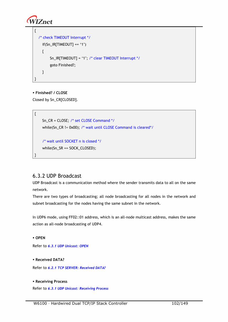
W6100 – Hardwired Dual TCP/IP Stack Controller 102/149
/* check TIMEOUT Interrupt */
if(Sn_IR[TIMEOUT] == ‘1’)
Sn_IR[TIMEOUT] = ‘1’; /* clear TIMEOUT Interrupt */
goto Finished?;
Finished? / CLOSE
Closed by Sn_CR[CLOSED].
Sn_CR = CLOSE; /* set CLOSE Command */
while(Sn_CR != 0x00); /* wait until CLOSE Command is cleared*/
/* wait until SOCKET n is closed */
while(Sn_SR == SOCK_CLOSED);
6.3.2 UDP Broadcast
UDP Broadcast is a communication method where the sender transmits data to all on the same
network.
There are two types of broadcasting; all node broadcasting for all nodes in the network and
subnet broadcasting for the nodes having the same subnet in the network.
In UDP6 mode, using FF02::01 address, which is an all-node multicast address, makes the same
action as all-node broadcasting of UDP4.
OPEN
Refer to 6.3.1 UDP Unicast: OPEN
Received DATA?
Refer to 6.2.1 TCP SERVER: Received DATA?
Receiving Process
Refer to 6.3.1 UDP Unicast: Receiving Process
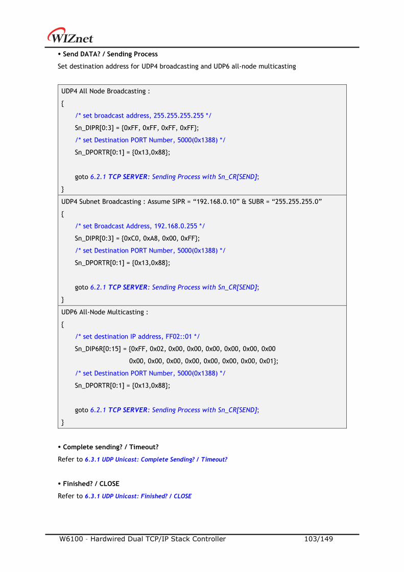
W6100 – Hardwired Dual TCP/IP Stack Controller 103/149
Send DATA? / Sending Process
Set destination address for UDP4 broadcasting and UDP6 all-node multicasting
UDP4 All Node Broadcasting :
/* set broadcast address, 255.255.255.255 */
Sn_DIPR[0:3] = 0xFF, 0xFF, 0xFF, 0xFF;
/* set Destination PORT Number, 5000(0x1388) */
Sn_DPORTR[0:1] = 0x13,0x88;
goto 6.2.1 TCP SERVER: Sending Process with Sn_CR[SEND];
UDP4 Subnet Broadcasting : Assume SIPR = “192.168.0.10” & SUBR = “255.255.255.0”
/* set Broadcast Address, 192.168.0.255 */
Sn_DIPR[0:3] = 0xC0, 0xA8, 0x00, 0xFF;
/* set Destination PORT Number, 5000(0x1388) */
Sn_DPORTR[0:1] = 0x13,0x88;
goto 6.2.1 TCP SERVER: Sending Process with Sn_CR[SEND];
UDP6 All-Node Multicasting :
/* set destination IP address, FF02::01 */
Sn_DIP6R[0:15] = 0xFF, 0x02, 0x00, 0x00, 0x00, 0x00, 0x00, 0x00
0x00, 0x00, 0x00, 0x00, 0x00, 0x00, 0x00, 0x01;
/* set Destination PORT Number, 5000(0x1388) */
Sn_DPORTR[0:1] = 0x13,0x88;
goto 6.2.1 TCP SERVER: Sending Process with Sn_CR[SEND];
Complete sending? / Timeout?
Refer to 6.3.1 UDP Unicast: Complete Sending? / Timeout?
Finished? / CLOSE
Refer to 6.3.1 UDP Unicast: Finished? / CLOSE
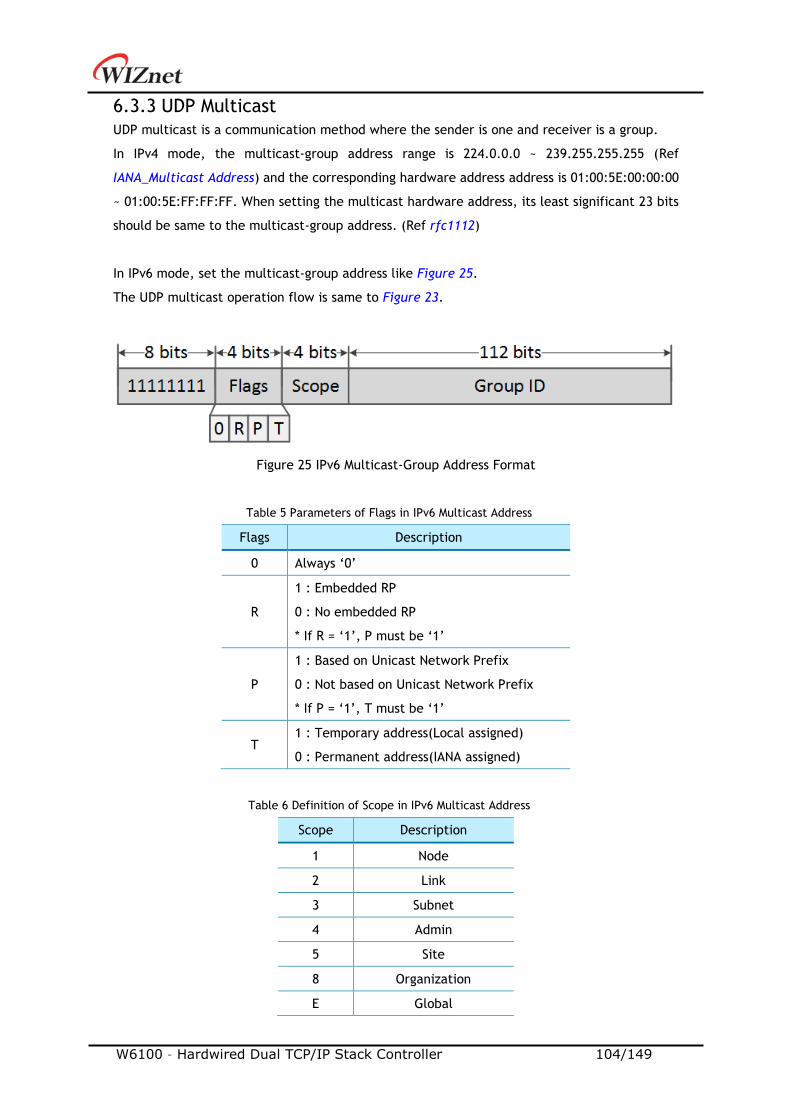
W6100 – Hardwired Dual TCP/IP Stack Controller 104/149
6.3.3 UDP Multicast
UDP multicast is a communication method where the sender is one and receiver is a group.
In IPv4 mode, the multicast-group address range is 224.0.0.0 ~ 239.255.255.255 (Ref
IANA_Multicast Address) and the corresponding hardware address address is 01:00:5E:00:00:00
~ 01:00:5E:FF:FF:FF. When setting the multicast hardware address, its least significant 23 bits
should be same to the multicast-group address. (Ref rfc1112)
In IPv6 mode, set the multicast-group address like Figure 25.
The UDP multicast operation flow is same to Figure 23.
Figure 25 IPv6 Multicast-Group Address Format
Table 5 Parameters of Flags in IPv6 Multicast Address
Flags Description
0 Always ‘0’
R
1 : Embedded RP
0 : No embedded RP
* If R = ‘1’, P must be ‘1’
P
1 : Based on Unicast Network Prefix
0 : Not based on Unicast Network Prefix
* If P = ‘1’, T must be ‘1’
T 1 : Temporary address(Local assigned)
0 : Permanent address(IANA assigned)
Table 6 Definition of Scope in IPv6 Multicast Address
Scope Description
1 Node
2 Link
3 Subnet
4 Admin
5 Site
8 Organization
E Global
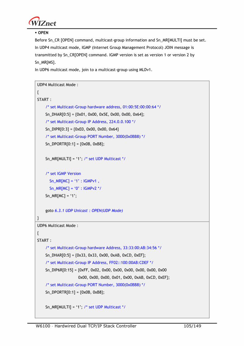
W6100 – Hardwired Dual TCP/IP Stack Controller 105/149
OPEN
Before Sn_CR [OPEN] command, multicast-group information and Sn_MR[MULTI] must be set.
In UDP4 multicast mode, IGMP (Internet Group Management Protocol) JOIN message is
transmitted by Sn_CR[OPEN] command. IGMP version is set as version 1 or version 2 by
Sn_MR[MS].
In UDP6 multicast mode, join to a multicast-group using MLDv1.
UDP4 Multicast Mode :
START :
/* set Multicast-Group hardware address, 01:00:5E:00:00:64 */
Sn_DHAR[0:5] = 0x01, 0x00, 0x5E, 0x00, 0x00, 0x64;
/* set Multicast-Group IP Address, 224.0.0.100 */
Sn_DIPR[0:3] = 0xE0, 0x00, 0x00, 0x64
/* set Multicast-Group PORT Number, 3000(0x0BB8) */
Sn_DPORTR[0:1] = 0x0B, 0xB8;
Sn_MR[MULTI] = ‘1’; /* set UDP Multicast */
/* set IGMP Version
Sn_MR[MC] = ‘1’ : IGMPv1 ,
Sn_MR[MC] = ‘0’ : IGMPv2 */
Sn_MR[MC] = ‘1’;
goto 6.3.1 UDP Unicast : OPEN(UDP Mode)
UDP6 Multicast Mode :
START :
/* set Multicast-Group hardware Address, 33:33:00:AB:34:56 */
Sn_DHAR[0:5] = 0x33, 0x33, 0x00, 0xAB, 0xCD, 0xEF;
/* set Multicast-Group IP Address, FF02::100:00AB:CDEF */
Sn_DIP6R[0:15] = 0xFF, 0x02, 0x00, 0x00, 0x00, 0x00, 0x00, 0x00
0x00, 0x00, 0x00, 0x01, 0x00, 0xAB, 0xCD, 0xEF;
/* set Multicast-Group PORT Number, 3000(0x0BB8) */
Sn_DPORTR[0:1] = 0x0B, 0xB8;
Sn_MR[MULTI] = ‘1’; /* set UDP Multicast */
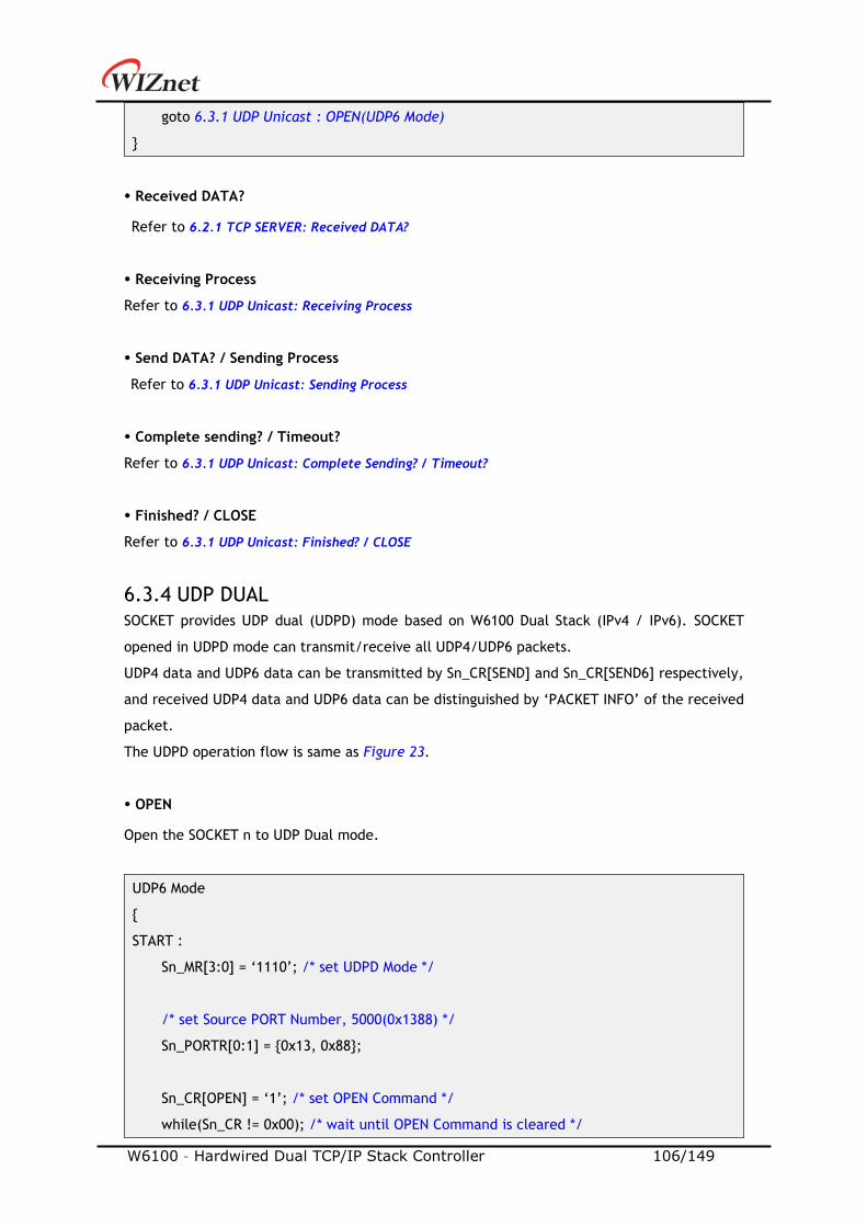
W6100 – Hardwired Dual TCP/IP Stack Controller 106/149
goto 6.3.1 UDP Unicast : OPEN(UDP6 Mode)
Received DATA?
Refer to 6.2.1 TCP SERVER: Received DATA?
Receiving Process
Refer to 6.3.1 UDP Unicast: Receiving Process
Send DATA? / Sending Process
Refer to 6.3.1 UDP Unicast: Sending Process
Complete sending? / Timeout?
Refer to 6.3.1 UDP Unicast: Complete Sending? / Timeout?
Finished? / CLOSE
Refer to 6.3.1 UDP Unicast: Finished? / CLOSE
6.3.4 UDP DUAL
SOCKET provides UDP dual (UDPD) mode based on W6100 Dual Stack (IPv4 / IPv6). SOCKET
opened in UDPD mode can transmit/receive all UDP4/UDP6 packets.
UDP4 data and UDP6 data can be transmitted by Sn_CR[SEND] and Sn_CR[SEND6] respectively,
and received UDP4 data and UDP6 data can be distinguished by ‘PACKET INFO’ of the received
packet.
The UDPD operation flow is same as Figure 23.
OPEN
Open the SOCKET n to UDP Dual mode.
UDP6 Mode
START :
Sn_MR[3:0] = ‘1110’; /* set UDPD Mode */
/* set Source PORT Number, 5000(0x1388) */
Sn_PORTR[0:1] = 0x13, 0x88;
Sn_CR[OPEN] = ‘1’; /* set OPEN Command */
while(Sn_CR != 0x00); /* wait until OPEN Command is cleared */
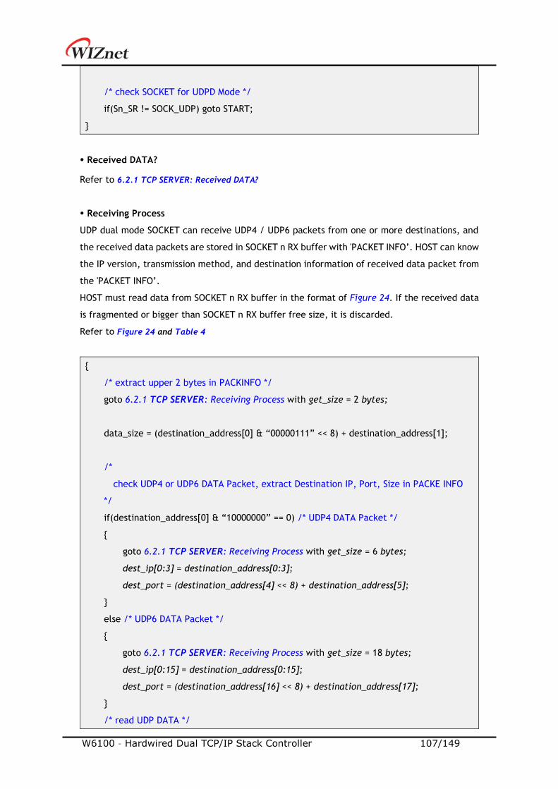
W6100 – Hardwired Dual TCP/IP Stack Controller 107/149
/* check SOCKET for UDPD Mode */
if(Sn_SR != SOCK_UDP) goto START;
Received DATA?
Refer to 6.2.1 TCP SERVER: Received DATA?
Receiving Process
UDP dual mode SOCKET can receive UDP4 / UDP6 packets from one or more destinations, and
the received data packets are stored in SOCKET n RX buffer with 'PACKET INFO’. HOST can know
the IP version, transmission method, and destination information of received data packet from
the 'PACKET INFO’.
HOST must read data from SOCKET n RX buffer in the format of Figure 24. If the received data
is fragmented or bigger than SOCKET n RX buffer free size, it is discarded.
Refer to Figure 24 and Table 4
/* extract upper 2 bytes in PACKINFO */
goto 6.2.1 TCP SERVER: Receiving Process with get_size = 2 bytes;
data_size = (destination_address[0] & “00000111” << 8) + destination_address[1];
/*
check UDP4 or UDP6 DATA Packet, extract Destination IP, Port, Size in PACKE INFO
*/
if(destination_address[0] & “10000000” == 0) /* UDP4 DATA Packet */
goto 6.2.1 TCP SERVER: Receiving Process with get_size = 6 bytes;
dest_ip[0:3] = destination_address[0:3];
dest_port = (destination_address[4] << 8) + destination_address[5];
else /* UDP6 DATA Packet */
goto 6.2.1 TCP SERVER: Receiving Process with get_size = 18 bytes;
dest_ip[0:15] = destination_address[0:15];
dest_port = (destination_address[16] << 8) + destination_address[17];
/* read UDP DATA */
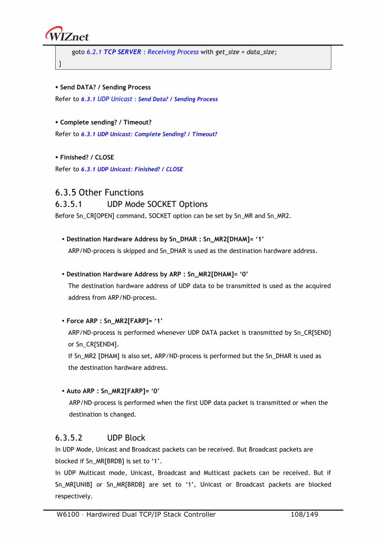
W6100 – Hardwired Dual TCP/IP Stack Controller 108/149
goto 6.2.1 TCP SERVER : Receiving Process with get_size = data_size;
Send DATA? / Sending Process
Refer to 6.3.1 UDP Unicast : Send Data? / Sending Process
Complete sending? / Timeout?
Refer to 6.3.1 UDP Unicast: Complete Sending? / Timeout?
Finished? / CLOSE
Refer to 6.3.1 UDP Unicast: Finished? / CLOSE
6.3.5 Other Functions
6.3.5.1 UDP Mode SOCKET Options
Before Sn_CR[OPEN] command, SOCKET option can be set by Sn_MR and Sn_MR2.
Destination Hardware Address by Sn_DHAR : Sn_MR2[DHAM]= ‘1’
ARP/ND-process is skipped and Sn_DHAR is used as the destination hardware address.
Destination Hardware Address by ARP : Sn_MR2[DHAM]= ‘0’
The destination hardware address of UDP data to be transmitted is used as the acquired
address from ARP/ND-process.
Force ARP : Sn_MR2[FARP]= ‘1’
ARP/ND-process is performed whenever UDP DATA packet is transmitted by Sn_CR[SEND]
or Sn_CR[SEND4].
If Sn_MR2 [DHAM] is also set, ARP/ND-process is performed but the Sn_DHAR is used as
the destination hardware address.
Auto ARP : Sn_MR2[FARP]= ‘0’
ARP/ND-process is performed when the first UDP data packet is transmitted or when the
destination is changed.
6.3.5.2 UDP Block
In UDP Mode, Unicast and Broadcast packets can be received. But Broadcast packets are
blocked if Sn_MR[BRDB] is set to ‘1’.
In UDP Multicast mode, Unicast, Broadcast and Multicast packets can be received. But if
Sn_MR[UNIB] or Sn_MR[BRDB] are set to ‘1’, Unicast or Broadcast packets are blocked
respectively.
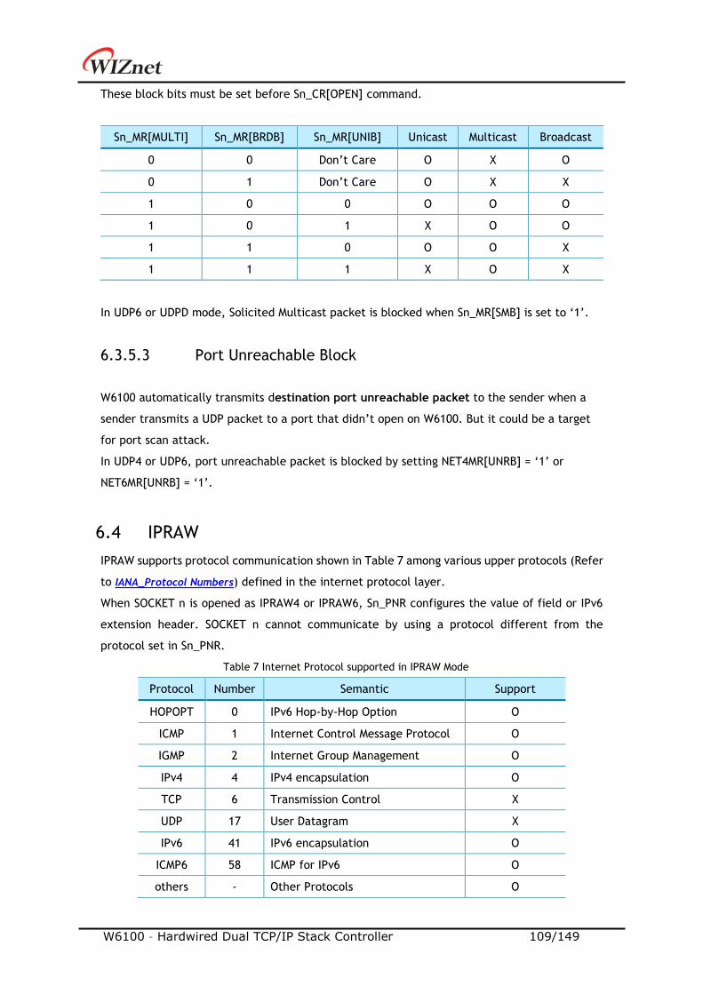
W6100 – Hardwired Dual TCP/IP Stack Controller 109/149
These block bits must be set before Sn_CR[OPEN] command.
Sn_MR[MULTI] Sn_MR[BRDB] Sn_MR[UNIB] Unicast Multicast Broadcast
0 0 Don’t Care O X O
0 1 Don’t Care O X X
1 0 0 O O O
1 0 1 X O O
1 1 0 O O X
1 1 1 X O X
In UDP6 or UDPD mode, Solicited Multicast packet is blocked when Sn_MR[SMB] is set to ‘1’.
6.3.5.3 Port Unreachable Block
W6100 automatically transmits destination port unreachable packet to the sender when a
sender transmits a UDP packet to a port that didn’t open on W6100. But it could be a target
for port scan attack.
In UDP4 or UDP6, port unreachable packet is blocked by setting NET4MR[UNRB] = ‘1’ or
NET6MR[UNRB] = ‘1’.
6.4 IPRAW
IPRAW supports protocol communication shown in Table 7 among various upper protocols (Refer
to IANA_Protocol Numbers) defined in the internet protocol layer.
When SOCKET n is opened as IPRAW4 or IPRAW6, Sn_PNR configures the value of field or IPv6
extension header. SOCKET n cannot communicate by using a protocol different from the
protocol set in Sn_PNR.
Table 7 Internet Protocol supported in IPRAW Mode
Protocol Number Semantic Support
HOPOPT 0 IPv6 Hop-by-Hop Option O
ICMP 1 Internet Control Message Protocol O
IGMP 2 Internet Group Management O
IPv4 4 IPv4 encapsulation O
TCP 6 Transmission Control X
UDP 17 User Datagram X
IPv6 41 IPv6 encapsulation O
ICMP6 58 ICMP for IPv6 O
others - Other Protocols O
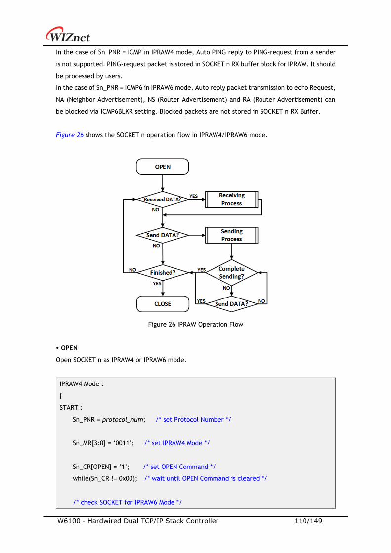
W6100 – Hardwired Dual TCP/IP Stack Controller 110/149
In the case of Sn_PNR = ICMP in IPRAW4 mode, Auto PING reply to PING-request from a sender
is not supported. PING-request packet is stored in SOCKET n RX buffer block for IPRAW. It should
be processed by users.
In the case of Sn_PNR = ICMP6 in IPRAW6 mode, Auto reply packet transmission to echo Request,
NA (Neighbor Advertisement), NS (Router Advertisement) and RA (Router Advertisement) can
be blocked via ICMP6BLKR setting. Blocked packets are not stored in SOCKET n RX Buffer.
Figure 26 shows the SOCKET n operation flow in IPRAW4/IPRAW6 mode.
Figure 26 IPRAW Operation Flow
OPEN
Open SOCKET n as IPRAW4 or IPRAW6 mode.
IPRAW4 Mode :
START :
Sn_PNR = protocol_num; /* set Protocol Number */
Sn_MR[3:0] = ‘0011’; /* set IPRAW4 Mode */
Sn_CR[OPEN] = ‘1’; /* set OPEN Command */
while(Sn_CR != 0x00); /* wait until OPEN Command is cleared */
/* check SOCKET for IPRAW6 Mode */
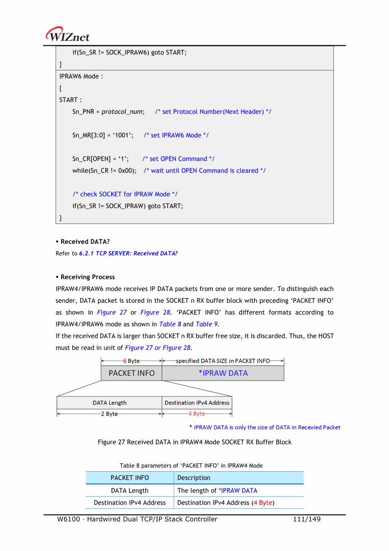
W6100 – Hardwired Dual TCP/IP Stack Controller 111/149
if(Sn_SR != SOCK_IPRAW6) goto START;
IPRAW6 Mode :
START :
Sn_PNR = protocol_num; /* set Protocol Number(Next Header) */
Sn_MR[3:0] = ‘1001’; /* set IPRAW6 Mode */
Sn_CR[OPEN] = ‘1’; /* set OPEN Command */
while(Sn_CR != 0x00); /* wait until OPEN Command is cleared */
/* check SOCKET for IPRAW Mode */
if(Sn_SR != SOCK_IPRAW) goto START;
Received DATA?
Refer to 6.2.1 TCP SERVER: Received DATA?
Receiving Process
IPRAW4/IPRAW6 mode receives IP DATA packets from one or more sender. To distinguish each
sender, DATA packet is stored in the SOCKET n RX buffer block with preceding ‘PACKET INFO’
as shown in Figure 27 or Figure 28. ‘PACKET INFO’ has different formats according to
IPRAW4/IPRAW6 mode as shown in Table 8 and Table 9.
If the received DATA is larger than SOCKET n RX buffer free size, it is discarded. Thus, the HOST
must be read in unit of Figure 27 or Figure 28.
Figure 27 Received DATA in IPRAW4 Mode SOCKET RX Buffer Block
Table 8 parameters of ‘PACKET INFO’ in IPRAW4 Mode
PACKET INFO Description
DATA Length The length of *IPRAW DATA
Destination IPv4 Address Destination IPv4 Address (4 Byte)

W6100 – Hardwired Dual TCP/IP Stack Controller 112/149
Figure 28 Received DATA in IPRAW6 Mode SOCKET RX Buffer Block
Table 9 parameters of ‘PACKET INFO’ in IPRAW6 Mode
PACKET INFO Description
IPv6 If IPv6 Packet is received, set to ‘1’
ALL If All Node Packet is received, set to ‘1’
MUL If Multicast Packet is received, set to ‘1’
GUA If Destination Address is GUA, set to ‘1’
LLA If Destination Address is LLA, set to ‘1’
DATA Length The length of *IPRAW DATA
Destination IPv6 Address Destination IPv6 Address (16 Byte)
IPRAW4 Mode :
/* receive PACKINFO */
goto 6.2.1 TCP S: Receiving Process with get_size = 6;
/* extract Destination DATA Size, IP Address in PACKET INFO*/
data_size = (destination_address[0] << 8) + destination_address[1];
dest_ip[0:3] = destination_address[2:5];
/* read UDP DATA */
goto 6.2.1 TCP SERVER : Receiving Process with get_size = data_size;
IPRAW6 Mode :
/* receive PACKINFO */
goto 6.2.1 TCP SERVER: Receiving Process with get_size = 18;
/* extract Destination Information, DATA Size, IP Address in PACKET INFO */
data_Info = destination_address[0] & “11111000”;
data_size = (destination_address[0] & “00000111” << 8) + (destination_address[1];
W6100 – Hardwired Dual TCP/IP Stack Controller 113/149
dest_ip[0:15] = destination_address[2:17];
/* read UDP DATA */
goto 6.2.1 TCP SERVER: Receiving Process with get_size = data_size;
Sending DATA? / Sending Process
Data to send must not exceed SOCKET n TX buffer free size. If data size is larger than MSS,
HOST must split the lager data into multiple MSS units.
MSS of IPRAW6 mode cannot be larger than 1460, MSS of IPRAW mode cannot be larger than
1480.
IPRAW4 Mode :
/* set Destination IP Address, 192.168.0.11 */
Sn_DIPR[0:3] = 0xC0, 0xA8, 0x00, 0x0B;
goto 6.2.1 TCP SERVER: Sending Process;
IPRAW6 Mode :
/* set destination IP address, FE80::10D:FC:34A:EF90 */
Sn_DIP6R[0:15] = 0xFE, 0x80, 0x00, 0x00, 0x00, 0x00, 0x00, 0x00
0x01, 0x0D, 0x00, 0xFC, 0x03, 0x4A, 0xEF, 0x90;
goto 6.2.1 TCP SERVER: Sending Process;
Complete sending? / Timeout?
ARP/ND-process is performed before first DATA packet is sent to by Sn_CR[SEND] or
Sn_CR[SEND6] or before DATA packet is sent to different destination from the previous
destination.
In ARP/ND-process, Sn_IR[TIMEOUT] may occur and the corresponding DATA packet is discarded.
Since IPRAW4 or IPRAW6 supports 1:N communication like as UDP, SOCKET n doesn’t close even
if Sn_IR[TIMEOUT] occurs (Refer to 0
Retransmission).
/* check TIMEOUT Interrupt */
W6100 – Hardwired Dual TCP/IP Stack Controller 114/149
if(Sn_IR[TIMEOUT] == ‘1’)
Sn_IR[TIMEOUT] = ‘1’; /* clear TIMEOUT Interrupt */
goto Finished?;
Finished? / CLOSE
In case that there is no more data to send, close SOCKET n by Sn_CR[CLOSE].
Sn_CR = CLOSE; /* set CLOSE Command */
while(Sn_CR != 0x00); /* wait until CLOSE Command is cleared*/
/* wait until SOCKET n is closed */
while(Sn_SR == SOCK_CLOSED);
6.4.1 Other Functions
6.4.1.1 IPRAW Mode SOCKET Options
In the process of opening SOCKER n as IPRAW4/IPRAW6 mode, SOCKET option is set via Sn_MR
and Sn_MR2.
Destination Hardware Address by Sn_DHAR : Sn_MR2[DHAM]= ‘1’
ARP/ND-process is skipped and Sn_DHAR is used as the destination hardware address.
Destination Hardware Address by ARP : Sn_MR2[DHAM]= ‘0’
The destination hardware address of IPRAW data to be transmitted is used as the acquired
address from ARP/ND-process.
Force ARP : Sn_MR2[FARP]= ‘1’
ARP/ND-process is performed whenever IPRAW4 or IPRAW6 DATA is transmitted by
Sn_CR[SEND] or Sn_CR[SEND6].
Auto ARP : Sn_MR2[FARP]= ‘0’
ARP/ND-process is performed when the first IPRAW data packet is transmitted or when
the destination is changed.
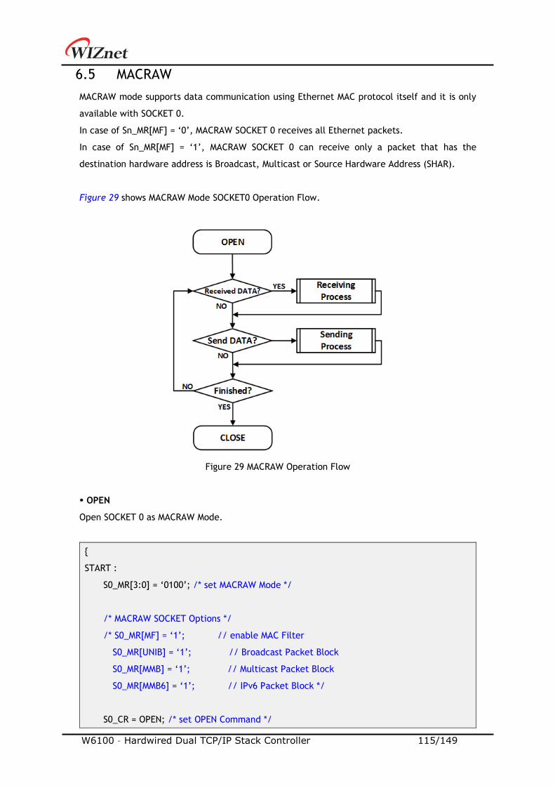
W6100 – Hardwired Dual TCP/IP Stack Controller 115/149
6.5 MACRAW
MACRAW mode supports data communication using Ethernet MAC protocol itself and it is only
available with SOCKET 0.
In case of Sn_MR[MF] = ‘0’, MACRAW SOCKET 0 receives all Ethernet packets.
In case of Sn_MR[MF] = ‘1’, MACRAW SOCKET 0 can receive only a packet that has the
destination hardware address is Broadcast, Multicast or Source Hardware Address (SHAR).
Figure 29 shows MACRAW Mode SOCKET0 Operation Flow.
Figure 29 MACRAW Operation Flow
OPEN
Open SOCKET 0 as MACRAW Mode.
START :
S0_MR[3:0] = ‘0100’; /* set MACRAW Mode */
/* MACRAW SOCKET Options */
/* S0_MR[MF] = ‘1’; // enable MAC Filter
S0_MR[UNIB] = ‘1’; // Broadcast Packet Block
S0_MR[MMB] = ‘1’; // Multicast Packet Block
S0_MR[MMB6] = ‘1’; // IPv6 Packet Block */
S0_CR = OPEN; /* set OPEN Command */
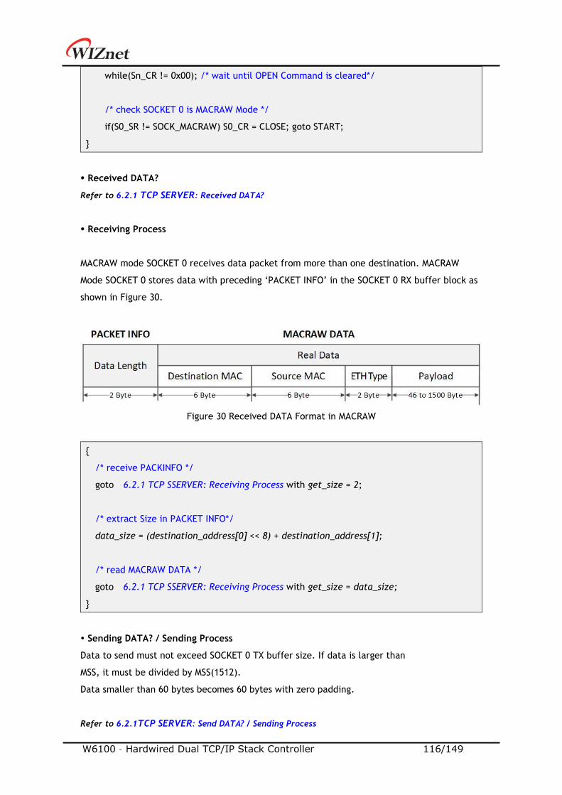
W6100 – Hardwired Dual TCP/IP Stack Controller 116/149
while(Sn_CR != 0x00); /* wait until OPEN Command is cleared*/
/* check SOCKET 0 is MACRAW Mode */
if(S0_SR != SOCK_MACRAW) S0_CR = CLOSE; goto START;
Received DATA?
Refer to 6.2.1 TCP SERVER: Received DATA?
Receiving Process
MACRAW mode SOCKET 0 receives data packet from more than one destination. MACRAW
Mode SOCKET 0 stores data with preceding ‘PACKET INFO’ in the SOCKET 0 RX buffer block as
shown in Figure 30.
Figure 30 Received DATA Format in MACRAW
/* receive PACKINFO */
goto 6.2.1 TCP SSERVER: Receiving Process with get_size = 2;
/* extract Size in PACKET INFO*/
data_size = (destination_address[0] << 8) + destination_address[1];
/* read MACRAW DATA */
goto 6.2.1 TCP SSERVER: Receiving Process with get_size = data_size;
Sending DATA? / Sending Process
Data to send must not exceed SOCKET 0 TX buffer size. If data is larger than
MSS, it must be divided by MSS(1512).
Data smaller than 60 bytes becomes 60 bytes with zero padding.
Refer to 6.2.1TCP SERVER: Send DATA? / Sending Process
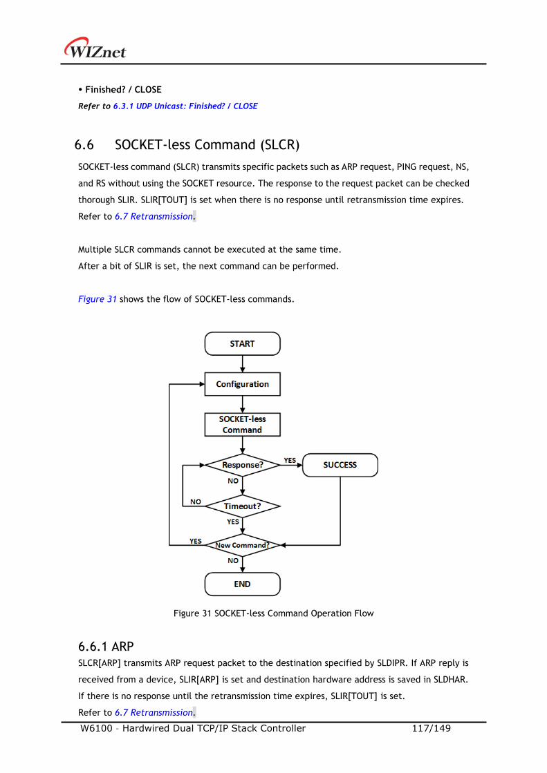
W6100 – Hardwired Dual TCP/IP Stack Controller 117/149
Finished? / CLOSE
Refer to 6.3.1 UDP Unicast: Finished? / CLOSE
6.6 SOCKET-less Command (SLCR)
SOCKET-less command (SLCR) transmits specific packets such as ARP request, PING request, NS,
and RS without using the SOCKET resource. The response to the request packet can be checked
thorough SLIR. SLIR[TOUT] is set when there is no response until retransmission time expires.
Refer to 6.7 Retransmission.
Multiple SLCR commands cannot be executed at the same time.
After a bit of SLIR is set, the next command can be performed.
Figure 31 shows the flow of SOCKET-less commands.
Figure 31 SOCKET-less Command Operation Flow
6.6.1 ARP
SLCR[ARP] transmits ARP request packet to the destination specified by SLDIPR. If ARP reply is
received from a device, SLIR[ARP] is set and destination hardware address is saved in SLDHAR.
If there is no response until the retransmission time expires, SLIR[TOUT] is set.
Refer to 6.7 Retransmission.
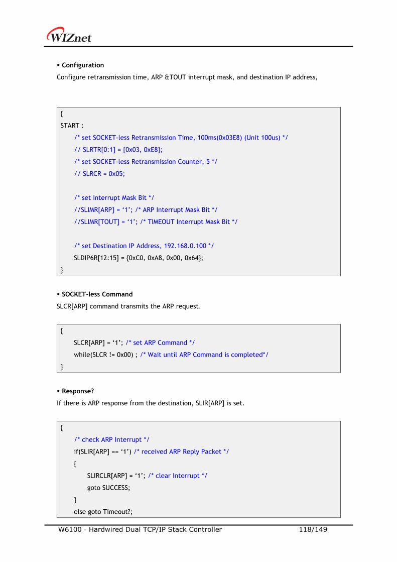
W6100 – Hardwired Dual TCP/IP Stack Controller 118/149
Configuration
Configure retransmission time, ARP &TOUT interrupt mask, and destination IP address,
START :
/* set SOCKET-less Retransmission Time, 100ms(0x03E8) (Unit 100us) */
// SLRTR[0:1] = 0x03, 0xE8;
/* set SOCKET-less Retransmission Counter, 5 */
// SLRCR = 0x05;
/* set Interrupt Mask Bit */
//SLIMR[ARP] = ‘1’; /* ARP Interrupt Mask Bit */
//SLIMR[TOUT] = ‘1’; /* TIMEOUT Interrupt Mask Bit */
/* set Destination IP Address, 192.168.0.100 */
SLDIP6R[12:15] = 0xC0, 0xA8, 0x00, 0x64;
SOCKET-less Command
SLCR[ARP] command transmits the ARP request.
SLCR[ARP] = ‘1’; /* set ARP Command */
while(SLCR != 0x00) ; /* Wait until ARP Command is completed*/
Response?
If there is ARP response from the destination, SLIR[ARP] is set.
/* check ARP Interrupt */
if(SLIR[ARP] == ‘1’) /* received ARP Reply Packet */
SLIRCLR[ARP] = ‘1’; /* clear Interrupt */
goto SUCCESS;
else goto Timeout?;
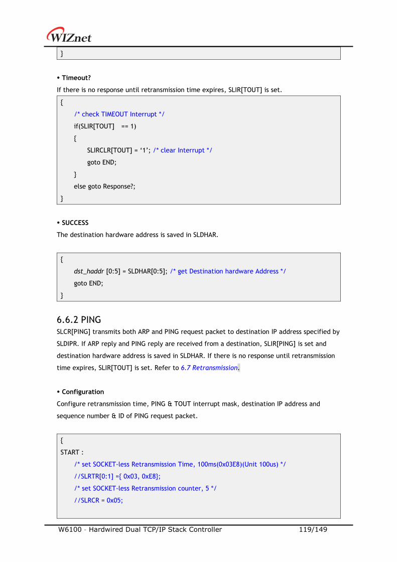
W6100 – Hardwired Dual TCP/IP Stack Controller 119/149
Timeout?
If there is no response until retransmission time expires, SLIR[TOUT] is set.
/* check TIMEOUT Interrupt */
if(SLIR[TOUT] == 1)
SLIRCLR[TOUT] = ‘1’; /* clear Interrupt */
goto END;
else goto Response?;
SUCCESS
The destination hardware address is saved in SLDHAR.
dst_haddr [0:5] = SLDHAR[0:5]; /* get Destination hardware Address */
goto END;
6.6.2 PING
SLCR[PING] transmits both ARP and PING request packet to destination IP address specified by
SLDIPR. If ARP reply and PING reply are received from a destination, SLIR[PING] is set and
destination hardware address is saved in SLDHAR. If there is no response until retransmission
time expires, SLIR[TOUT] is set. Refer to 6.7 Retransmission.
Configuration
Configure retransmission time, PING & TOUT interrupt mask, destination IP address and
sequence number & ID of PING request packet.
START :
/* set SOCKET-less Retransmission Time, 100ms(0x03E8)(Unit 100us) */
//SLRTR[0:1] = 0x03, 0xE8;
/* set SOCKET-less Retransmission counter, 5 */
//SLRCR = 0x05;
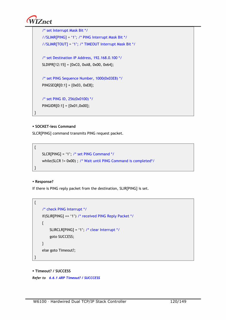
W6100 – Hardwired Dual TCP/IP Stack Controller 120/149
/* set Interrupt Mask Bit */
//SLIMR[PING] = ‘1’; /* PING Interrupt Mask Bit */
//SLIMR[TOUT] = ‘1’; /* TIMEOUT Interrupt Mask Bit */
/* set Destination IP Address, 192.168.0.100 */
SLDIPR[12:15] = 0xC0, 0xA8, 0x00, 0x64;
/* set PING Sequence Number, 1000(0x03E8) */
PINGSEQR[0:1] = 0x03, 0xE8;
/* set PING ID, 256(0x0100) */
PINGIDR[0:1] = 0x01,0x00;
SOCKET-less Command
SLCR[PING] command transmits PING request packet.
SLCR[PING] = ‘1’; /* set PING Command */
while(SLCR != 0x00) ; /* Wait until PING Command is completed*/
Response?
If there is PING reply packet from the destination, SLIR[PING] is set.
/* check PING Interrupt */
if(SLIR[PING] == ‘1’) /* received PING Reply Packet */
SLIRCLR[PING] = ‘1’; /* clear Interrupt */
goto SUCCESS;
else goto Timeout?;
Timeout? / SUCCESS
Refer to 6.6.1 ARP Timeout? / SUCCCESS

W6100 – Hardwired Dual TCP/IP Stack Controller 121/149
6.6.3 ARP6 (ND, Neighbor Discovery)
SLCR[ARP6] transmits ICMPv6 NS (Neighbor Solicitation) packet to destination IP address
specified by SLDIP6R and it is similar to ARP-process. If NA (Neighbor Advertisement) is
received from destination, SLIR[ARP6] is set and destination hardware address is saved in
SLDHAR. If there is no response until the retransmission time, SLIR[TOUT] is set.
Refer to 6.7 Retransmission.
Configuration
Configure retransmission time, ARP6 & TOUT interrupt mask and destination IP address.
START :
/* set SOCKET-less Retransmission Timer, 100ms(0x03E8) (Unit 100us) */
//SLRTR[0:1] = 0x03, 0xE8;
/* set SOCKET-less Retransmission Counter, 5 */
//SLRCR = 0x05;
/* set Interrupt Mask Bit */
//SLIMR[ARP6] = ‘1’; /* ARP6 Interrupt Mask Bit */
//SLIMR[TOUT] = ‘1’; /* TIMEOUT Interrupt Mask Bit */
/* set Target IP Address, FE80::1D0:AABB:CCDD */
SLDIP6R[0:15] = 0xFE, 0x80, 0x00, 0x01, 0x00, 0x00, 0x00, 0x00,
0x13, 0x22, 0x33, 0xFF, 0xFE, 0xAA, 0xBB, 0xCC ;
SOCKET-less Command
SLCR[ARP6] command transmits NS packet
SLCR[ARP6] = ‘1’; /* set ARP6 Command */
while(SLCR != 0x00) ; /* Wait until ARP6 Command is completed*/
Response?
If there is NA packet from the destination, SLIR[ARP6] is set.
/* check ND Interrupt */
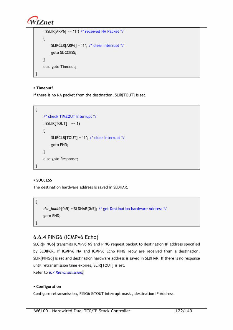
W6100 – Hardwired Dual TCP/IP Stack Controller 122/149
if(SLIR[ARP6] == ‘1’) /* received NA Packet */
SLIRCLR[ARP6] = ‘1’; /* clear Interrupt */
goto SUCCESS;
else goto Timeout;
Timeout?
If there is no NA packet from the destination, SLIR[TOUT] is set.
/* check TIMEOUT Interrupt */
if(SLIR[TOUT] == 1)
SLIRCLR[TOUT] = ‘1’; /* clear Interrupt */
goto END;
else goto Response;
SUCCESS
The destination hardware address is saved in SLDHAR.
dst_haddr[0:5] = SLDHAR[0:5]; /* get Destination hardware Address */
goto END;
6.6.4 PING6 (ICMPv6 Echo)
SLCR[PING6] transmits ICMPv6 NS and PING request packet to destination IP address specified
by SLDIP6R. If ICMPv6 NA and ICMPv6 Echo PING reply are received from a destination,
SLIR[PING6] is set and destination hardware address is saved in SLDHAR. If there is no response
until retransmission time expires, SLIR[TOUT] is set.
Refer to 6.7 Retransmission.
Configuration
Configure retransmission, PING6 &TOUT interrupt mask , destination IP Address.
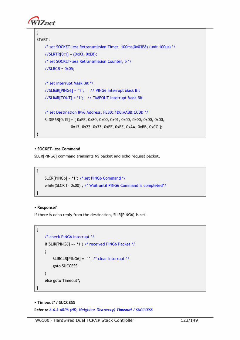
W6100 – Hardwired Dual TCP/IP Stack Controller 123/149
START :
/* set SOCKET-less Retransmission Timer, 100ms(0x03E8) (unit 100us) */
//SLRTR[0:1] = 0x03, 0xE8;
/* set SOCKET-less Retransmission Counter, 5 */
//SLRCR = 0x05;
/* set Interrupt Mask Bit */
//SLIMR[PING6] = ‘1’; // PING6 Interrupt Mask Bit
//SLIMR[TOUT] = ‘1’; // TIMEOUT Interrupt Mask Bit
/* set Destination IPv6 Address, FE80::1D0:AABB:CCDD */
SLDIP6R[0:15] = 0xFE, 0x80, 0x00, 0x01, 0x00, 0x00, 0x00, 0x00,
0x13, 0x22, 0x33, 0xFF, 0xFE, 0xAA, 0xBB, 0xCC ;
SOCKET-less Command
SLCR[PING6] command transmits NS packet and echo request packet.
SLCR[PING6] = ‘1’; /* set PING6 Command */
while(SLCR != 0x00) ; /* Wait until PING6 Command is completed*/
Response?
If there is echo reply from the destination, SLIR[PING6] is set.
/* check PING6 Interrupt */
if(SLIR[PING6] == ‘1’) /* received PING6 Packet */
SLIRCLR[PING6] = ‘1’; /* clear Interrupt */
goto SUCCESS;
else goto Timeout?;
Timeout? / SUCCESS
Refer to 6.6.3 ARP6 (ND, Neighbor Discovery) Timeout? / SUCCCESS
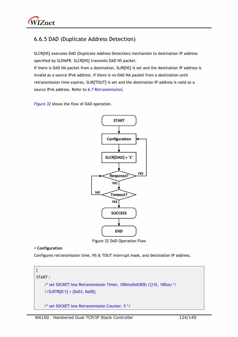
W6100 – Hardwired Dual TCP/IP Stack Controller 124/149
6.6.5 DAD (Duplicate Address Detection)
SLCR[NS] executes DAD (Duplicate Address Detection) mechanism to destination IP address
specified by SLDI6PR. SLCR[NS] transmits DAD NS packet.
If there is DAD NA packet from a destination, SLIR[NS] is set and the destination IP address is
invalid as a source IPv6 address. If there is no DAD NA packet from a destination until
retransmission time expires, SLIR[TOUT] is set and the destination IP address is valid as a
source IPv6 address. Refer to 6.7 Retransmission.
Figure 32 shows the flow of DAD operation.
Figure 32 DAD Operation Flow
Configuration
Configures retransmission time, NS & TOUT interrupt mask, and destination IP address.
START :
/* set SOCKET-less Retransmission Timer, 100ms(0x03E8) (단위, 100us) */
//SLRTR[0:1] = 0x03, 0xE8;
/* set SOCKET-less Retransmission Counter, 5 */
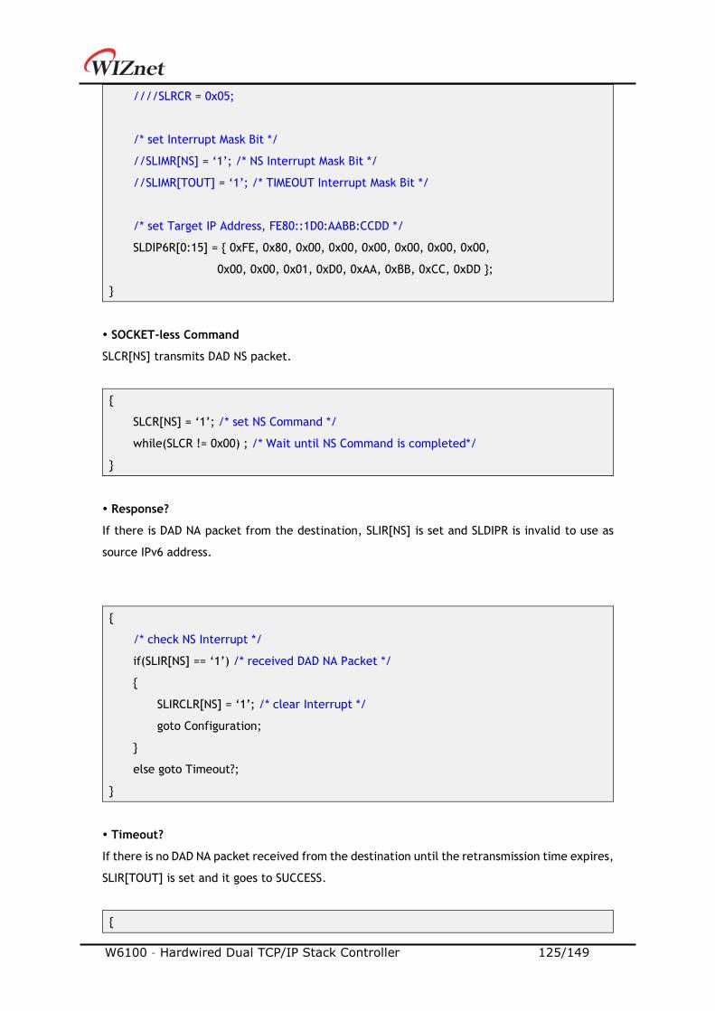
W6100 – Hardwired Dual TCP/IP Stack Controller 125/149
////SLRCR = 0x05;
/* set Interrupt Mask Bit */
//SLIMR[NS] = ‘1’; /* NS Interrupt Mask Bit */
//SLIMR[TOUT] = ‘1’; /* TIMEOUT Interrupt Mask Bit */
/* set Target IP Address, FE80::1D0:AABB:CCDD */
SLDIP6R[0:15] = 0xFE, 0x80, 0x00, 0x00, 0x00, 0x00, 0x00, 0x00,
0x00, 0x00, 0x01, 0xD0, 0xAA, 0xBB, 0xCC, 0xDD ;
SOCKET-less Command
SLCR[NS] transmits DAD NS packet.
SLCR[NS] = ‘1’; /* set NS Command */
while(SLCR != 0x00) ; /* Wait until NS Command is completed*/
Response?
If there is DAD NA packet from the destination, SLIR[NS] is set and SLDIPR is invalid to use as
source IPv6 address.
/* check NS Interrupt */
if(SLIR[NS] == ‘1’) /* received DAD NA Packet */
SLIRCLR[NS] = ‘1’; /* clear Interrupt */
goto Configuration;
else goto Timeout?;
Timeout?
If there is no DAD NA packet received from the destination until the retransmission time expires,
SLIR[TOUT] is set and it goes to SUCCESS.
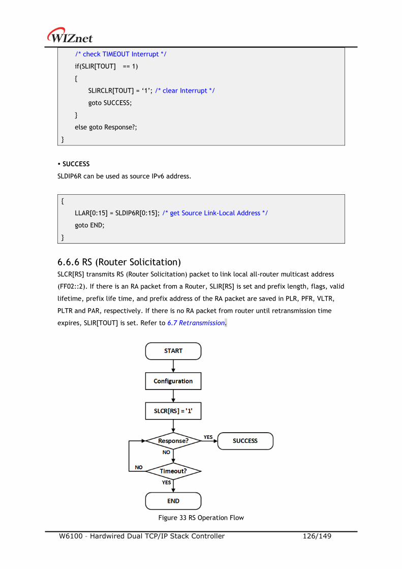
W6100 – Hardwired Dual TCP/IP Stack Controller 126/149
/* check TIMEOUT Interrupt */
if(SLIR[TOUT] == 1)
SLIRCLR[TOUT] = ‘1’; /* clear Interrupt */
goto SUCCESS;
else goto Response?;
SUCCESS
SLDIP6R can be used as source IPv6 address.
LLAR[0:15] = SLDIP6R[0:15]; /* get Source Link-Local Address */
goto END;
6.6.6 RS (Router Solicitation)
SLCR[RS] transmits RS (Router Solicitation) packet to link local all-router multicast address
(FF02::2). If there is an RA packet from a Router, SLIR[RS] is set and prefix length, flags, valid
lifetime, prefix life time, and prefix address of the RA packet are saved in PLR, PFR, VLTR,
PLTR and PAR, respectively. If there is no RA packet from router until retransmission time
expires, SLIR[TOUT] is set. Refer to 6.7 Retransmission.
Figure 33 RS Operation Flow
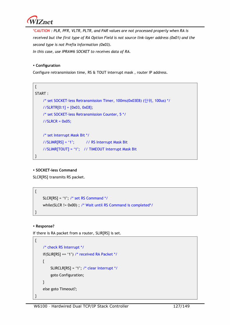
W6100 – Hardwired Dual TCP/IP Stack Controller 127/149
*CAUTION : PLR, PFR, VLTR, PLTR, and PAR values are not processed properly when RA is
received but the first type of RA Option Field is not source link-layer address (0x01) and the
second type is not Prefix Information (0x03).
In this case, use IPRAW6 SOCKET to receives data of RA.
Configuration
Configure retransmission time, RS & TOUT interrupt mask , router IP address.
START :
/* set SOCKET-less Retransmission Timer, 100ms(0x03E8) (단위, 100us) */
//SLRTR[0:1] = 0x03, 0xE8;
/* set SOCKET-less Retransmission Counter, 5 */
//SLRCR = 0x05;
/* set Interrupt Mask Bit */
//SLIMR[RS] = ‘1’; // RS Interrupt Mask Bit
//SLIMR[TOUT] = ‘1’; // TIMEOUT Interrupt Mask Bit
SOCKET-less Command
SLCR[RS] transmits RS packet.
SLCR[RS] = ‘1’; /* set RS Command */
while(SLCR != 0x00) ; /* Wait until RS Command is completed*/
Response?
If there is RA packet from a router, SLIR[RS] is set.
/* check RS Interrupt */
if(SLIR[RS] == ‘1’) /* received RA Packet */
SLIRCLR[RS] = ‘1’; /* clear Interrupt */
goto Configuration;
else goto Timeout?;

W6100 – Hardwired Dual TCP/IP Stack Controller 128/149
Timeout?
If there is no RA packet during retransmission time, SLIR[TOUT] is set.
/* check TIMEOUT Interrupt */
if(SLIR[TOUT] == 1)
SLIRCLR[TOUT] = ‘1’; /* clear Interrupt */
goto SUCCESS;
else goto Response?;
SUCCESS
Prefix length, flags, valid lifetime, prefix lifetime, and prefix address of the RA packet are
saved in PLR, PFR, VLTR, PLTR, and PAR, respectively.
Prefix_length = PLR; /* RA Prefix Length */
Flags = RAFLGR; /* RA Flags */
Valid_Lifetime = VLTR; /* RA Valid Life Time */
Prefix_Lifetime = PLTR; /* RA Prefix Life Time */
Prefix_address[0:15] = PAR[0:15]; /* RA Prefix Address */
6.6.7 Unsolicited NA(Neighbor Advertisement)
SLCR[NA] transmits unsolicited NA packet. Destination address is automatically configured
FF02::1(All-Node Multicast Address) and Target address is automatically configured by LLAR or
GUAR according to SLPR.
Because Unsolicited NA is an unresponsive message, SLIR [TIOUT] is set when the transmission
is completed.
Figure 34 shows the flow of unsolicited NA operation.
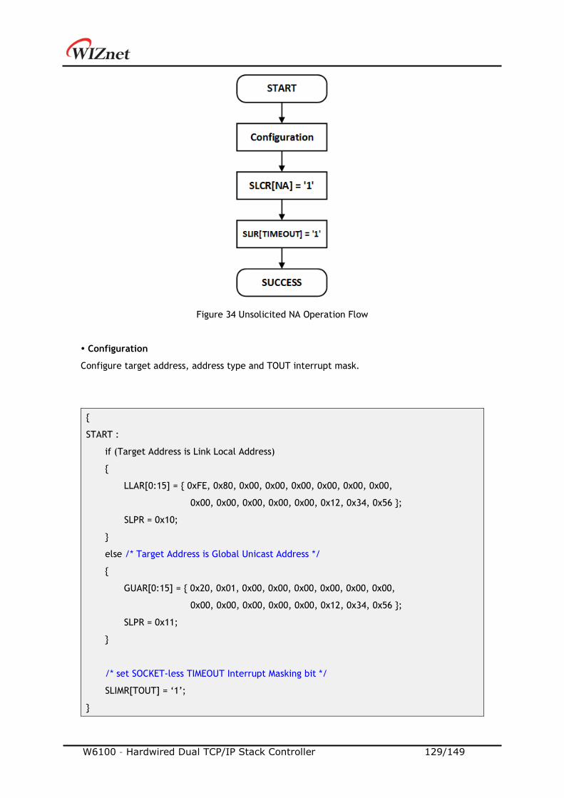
W6100 – Hardwired Dual TCP/IP Stack Controller 129/149
Figure 34 Unsolicited NA Operation Flow
Configuration
Configure target address, address type and TOUT interrupt mask.
START :
if (Target Address is Link Local Address)
LLAR[0:15] = 0xFE, 0x80, 0x00, 0x00, 0x00, 0x00, 0x00, 0x00,
0x00, 0x00, 0x00, 0x00, 0x00, 0x12, 0x34, 0x56 ;
SLPR = 0x10;
else /* Target Address is Global Unicast Address */
GUAR[0:15] = 0x20, 0x01, 0x00, 0x00, 0x00, 0x00, 0x00, 0x00,
0x00, 0x00, 0x00, 0x00, 0x00, 0x12, 0x34, 0x56 ;
SLPR = 0x11;
/* set SOCKET-less TIMEOUT Interrupt Masking bit */
SLIMR[TOUT] = ‘1’;
W6100 – Hardwired Dual TCP/IP Stack Controller 130/149
SOCKET-less Command
SLCR[NA] transmits unsolicited NA packet to all-node.
SLCR[NA] = ‘1’; /* set Unsolicited NA Command */
while(SLCR != 0x00) ; /* Wait until Unsolicited NA Command is completed*/
Timeout
SLIR[TOUT] is set when the transmission is completed.
/* check TIMEOUT Interrupt */
if(SLIR[TOUT] == 1)
SLIRCLR[TOUT] = ‘1’; /* clear Interrupt */
goto SUCCESS;
6.7 Retransmission
6.7.1 ARP & PING & ND Retransmission
When there is no response from a destination against of ARP/PING/ND Packet, ARP/PING/ND
retransmission is performed. In retransmission process, the request packet is retransmitted
every RTR until the response packet is received. And if the count of retransmission exceeds
RCR, TIMEOUT occurs. The below table shows retransmission TIMEOUT (ARPTO, PINGTO, NDTO).
ARPTO, PINGTO, NDTO = (TIMEOUTVAL x 0.1ms) x (TIMEOUTCNT + 1)
TIMEOUTVAL = SLRTR or Sn_RTR TIMEOUTCNT = SLRCR or Sn_RCR
Ex) TIMEOUTVAL = 2000(0x07D0), TIMEOUTCNT = 8(0x0008)
ARPTO= 2000 X 0.1ms X 9 = 1.8s
ARPTO occurs when there is no response from a destination in ARP-process by Sn_CR [CONNECT]
in TCP4 mode, Sn_CR[SEND] in UDP4 & IPRAW4 mode, and SLCR[ARP] in SOCKET-less command.
Sn_IR[TIMEOUT] or SLIR[TOUT] is set by ARPTO.
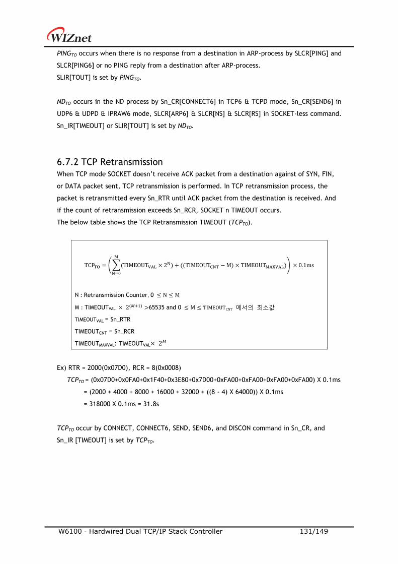
W6100 – Hardwired Dual TCP/IP Stack Controller 131/149
PINGTO occurs when there is no response from a destination in ARP-process by SLCR[PING] and
SLCR[PING6] or no PING reply from a destination after ARP-process.
SLIR[TOUT] is set by PINGTO.
NDTO occurs in the ND process by Sn_CR[CONNECT6] in TCP6 & TCPD mode, Sn_CR[SEND6] in
UDP6 & UDPD & IPRAW6 mode, SLCR[ARP6] & SLCR[NS] & SLCR[RS] in SOCKET-less command.
Sn_IR[TIMEOUT] or SLIR[TOUT] is set by NDTO.
6.7.2 TCP Retransmission
When TCP mode SOCKET doesn’t receive ACK packet from a destination against of SYN, FIN,
or DATA packet sent, TCP retransmission is performed. In TCP retransmission process, the
packet is retransmitted every Sn_RTR until ACK packet from the destination is received. And
if the count of retransmission exceeds Sn_RCR, SOCKET n TIMEOUT occurs.
The below table shows the TCP Retransmission TIMEOUT (TCPTO).
TCPTO = (∑(TIMEOUTVAL × 2N)
M
N=0
+ ((TIMEOUTCNT − M) × TIMEOUTMAXVAL)) × 0.1ms
N : Retransmission Counter, 0 ≤ N ≤ M
M : TIMEOUTVAL × 2(𝑀+1) >65535 and 0 ≤ M ≤ TIMEOUTCNT 에서의 최소값
TIMEOUTVAL = Sn_RTR
TIMEOUTCNT = Sn_RCR
TIMEOUTMAXVAL: TIMEOUTVAL× 2𝑀
Ex) RTR = 2000(0x07D0), RCR = 8(0x0008)
TCPTO = (0x07D0+0x0FA0+0x1F40+0x3E80+0x7D00+0xFA00+0xFA00+0xFA00+0xFA00) X 0.1ms
= (2000 + 4000 + 8000 + 16000 + 32000 + ((8 - 4) X 64000)) X 0.1ms
= 318000 X 0.1ms = 31.8s
TCPTO occur by CONNECT, CONNECT6, SEND, SEND6, and DISCON command in Sn_CR, and
Sn_IR [TIMEOUT] is set by TCPTO.
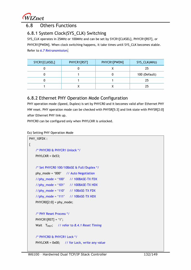
W6100 – Hardwired Dual TCP/IP Stack Controller 132/149
6.8 Others Functions
6.8.1 System Clock(SYS_CLK) Switching
SYS_CLK operates in 25MHz or 100MHz and can be set by SYCR1[CLKSEL], PHYCR1[RST], or
PHYCR1[PWDN]. When clock switching happens, it take times until SYS_CLK becomes stable.
Refer to 6.7 Retransmission.
SYCR1[CLKSEL] PHYCR1[RST] PHYCR1[PWDN] SYS_CLK(MHz)
0 0 X 25
0 1 0 100 (Default)
0 1 1 25
1 X X 25
6.8.2 Ethernet PHY Operation Mode Configuration
PHY operation mode (Speed, Duplex) is set by PHYCR0 and it becomes valid after Ethernet PHY
HW reset. PHY operation mode can be checked with PHYSR[5:3] and link state with PHYSR[2:0]
after Ethernet PHY link up.
PHYCR0 can be configured only when PHYLCKR is unlocked.
Ex) Setting PHY Operation Mode
PHY_10FDX :
/* PHYCR0 & PHYCR1 Unlock */
PHYLCKR = 0x53;
/* Set PHYCR0 100/10BASE & Full/Duplex */
phy_mode = ‘000’ // Auto Negotiation
//phy_mode = ‘100’ // 100BASE-TX FDX
//phy_mode = ‘101’ // 100BASE-TX HDX
//phy_mode = ‘110’ // 10BASE-TX FDX
//phy_mode = ‘111’ // 10BASE-TX HDX
PHYCR0[2:0] = phy_mode;
/* PHY Reset Process */
PHYCR1[RST] = ‘1’;
Wait TPRST; // refer to 8.4.1 Reset Timing
/* PHYCR0 & PHYCR1 Lock */
PHYLCKR = 0x00; // for Lock, write any value
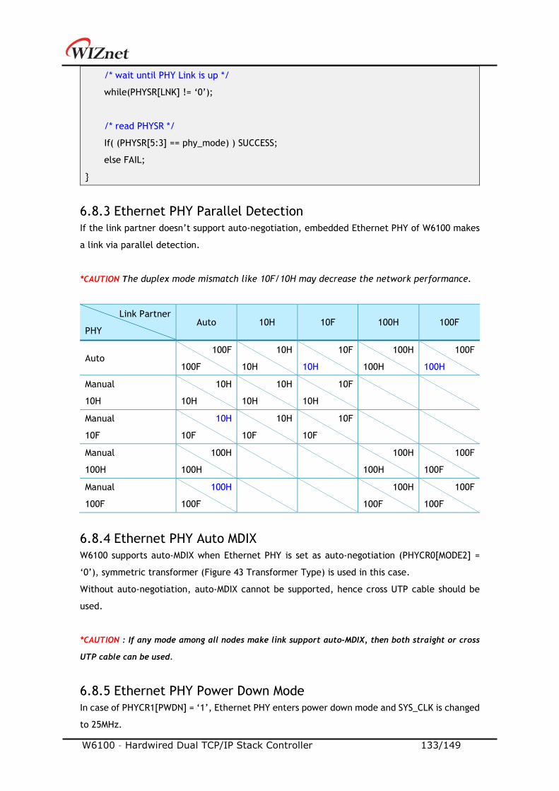
W6100 – Hardwired Dual TCP/IP Stack Controller 133/149
/* wait until PHY Link is up */
while(PHYSR[LNK] != ‘0’);
/* read PHYSR */
If( (PHYSR[5:3] == phy_mode) ) SUCCESS;
else FAIL;
6.8.3 Ethernet PHY Parallel Detection
If the link partner doesn’t support auto-negotiation, embedded Ethernet PHY of W6100 makes
a link via parallel detection.
*CAUTION The duplex mode mismatch like 10F/10H may decrease the network performance.
Link Partner
PHY Auto 10H 10F 100H 100F
Auto 100F
100F
10H
10H
10F
10H
100H
100H
100F
100H
Manual
10H
10H
10H
10H
10H
10F
10H
Manual
10F
10H
10F
10H
10F
10F
10F
Manual
100H
100H
100H
100H
100H
100F
100F
Manual
100F
100H
100F
100H
100F
100F
100F
6.8.4 Ethernet PHY Auto MDIX
W6100 supports auto-MDIX when Ethernet PHY is set as auto-negotiation (PHYCR0[MODE2] =
‘0’), symmetric transformer (Figure 43 Transformer Type) is used in this case.
Without auto-negotiation, auto-MDIX cannot be supported, hence cross UTP cable should be
used.
*CAUTION : If any mode among all nodes make link support auto-MDIX, then both straight or cross
UTP cable can be used.
6.8.5 Ethernet PHY Power Down Mode
In case of PHYCR1[PWDN] = ‘1’, Ethernet PHY enters power down mode and SYS_CLK is changed
to 25MHz.
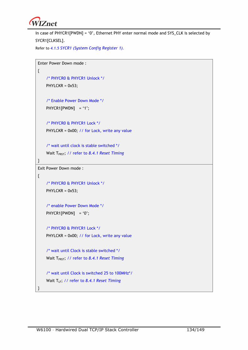
W6100 – Hardwired Dual TCP/IP Stack Controller 134/149
In case of PHYCR1[PWDN] = ‘0’, Ethernet PHY enter normal mode and SYS_CLK is selected by
SYCR1[CLKSEL].
Refer to 4.1.5 SYCR1 (System Config Register 1).
Enter Power Down mode :
/* PHYCR0 & PHYCR1 Unlock */
PHYLCKR = 0x53;
/* Enable Power Down Mode */
PHYCR1[PWDN] = ‘1’;
/* PHYCR0 & PHYCR1 Lock */
PHYLCKR = 0x00; // for Lock, write any value
/* wait until clock is stable switched */
Wait TPRST; // refer to 8.4.1 Reset Timing
Exit Power Down mode :
/* PHYCR0 & PHYCR1 Unlock */
PHYLCKR = 0x53;
/* enable Power Down Mode */
PHYCR1[PWDN] = ‘0’;
/* PHYCR0 & PHYCR1 Lock */
PHYLCKR = 0x00; // for Lock, write any value
/* wait until Clock is stable switched */
Wait TPRST; // refer to 8.4.1 Reset Timing
/* wait until Clock is switched 25 to 100MHz*/
Wait TLF; // refer to 8.4.1 Reset Timing
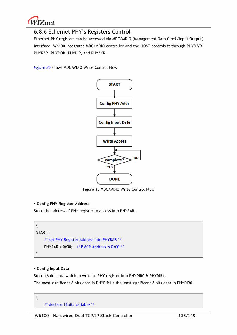
W6100 – Hardwired Dual TCP/IP Stack Controller 135/149
6.8.6 Ethernet PHY’s Registers Control
Ethernet PHY registers can be accessed via MDC/MDIO (Management Data Clock/Input Output)
interface. W6100 integrates MDC/MDIO controller and the HOST controls it through PHYDIVR,
PHYRAR, PHYDOR, PHYDIR, and PHYACR.
Figure 35 shows MDC/MDIO Write Control Flow.
Figure 35 MDC/MDIO Write Control Flow
Config PHY Register Address
Store the address of PHY register to access into PHYRAR.
START :
/* set PHY Register Address into PHYRAR */
PHYRAR = 0x00; /* BMCR Address is 0x00 */
Config Input Data
Store 16bits data which to write to PHY register into PHYDIR0 & PHYDIR1.
The most significant 8 bits data in PHYDIR1 / the least significant 8 bits data in PHYDIR0.
/* declare 16bits variable */
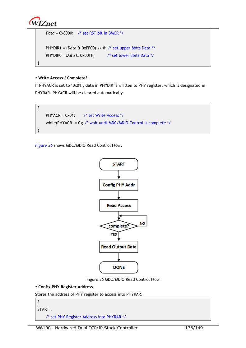
W6100 – Hardwired Dual TCP/IP Stack Controller 136/149
Data = 0x8000; /* set RST bit in BMCR */
PHYDIR1 = (Data & 0xFF00) >> 8; /* set upper 8bits Data */
PHYDIR0 = Data & 0x00FF; /* set lower 8bits Data */
Write Access / Complete?
If PHYACR is set to ‘0x01’, data in PHYDIR is written to PHY register, which is designated in
PHYRAR. PHYACR will be cleared automatically.
PHYACR = 0x01; /* set Write Access */
while(PHYACR != 0); /* wait until MDC/MDIO Control is complete */
Figure 36 shows MDC/MDIO Read Control Flow.
Figure 36 MDC/MDIO Read Control Flow
Config PHY Register Address
Stores the address of PHY register to access into PHYRAR.
START :
/* set PHY Register Address into PHYRAR */
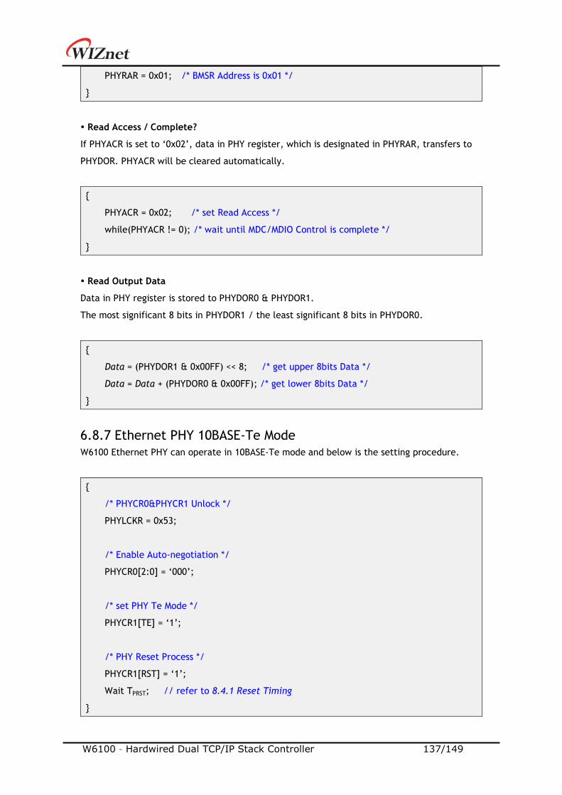
W6100 – Hardwired Dual TCP/IP Stack Controller 137/149
PHYRAR = 0x01; /* BMSR Address is 0x01 */
Read Access / Complete?
If PHYACR is set to ‘0x02’, data in PHY register, which is designated in PHYRAR, transfers to
PHYDOR. PHYACR will be cleared automatically.
PHYACR = 0x02; /* set Read Access */
while(PHYACR != 0); /* wait until MDC/MDIO Control is complete */
Read Output Data
Data in PHY register is stored to PHYDOR0 & PHYDOR1.
The most significant 8 bits in PHYDOR1 / the least significant 8 bits in PHYDOR0.
Data = (PHYDOR1 & 0x00FF) << 8; /* get upper 8bits Data */
Data = Data + (PHYDOR0 & 0x00FF); /* get lower 8bits Data */
6.8.7 Ethernet PHY 10BASE-Te Mode
W6100 Ethernet PHY can operate in 10BASE-Te mode and below is the setting procedure.
/* PHYCR0&PHYCR1 Unlock */
PHYLCKR = 0x53;
/* Enable Auto-negotiation */
PHYCR0[2:0] = ‘000’;
/* set PHY Te Mode */
PHYCR1[TE] = ‘1’;
/* PHY Reset Process */
PHYCR1[RST] = ‘1’;
Wait TPRST; // refer to 8.4.1 Reset Timing
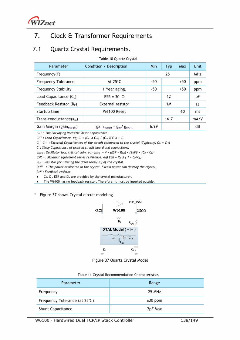
W6100 – Hardwired Dual TCP/IP Stack Controller 138/149
7. Clock & Transformer Requirements
7.1 Quartz Crystal Requirements.
Table 10 Quartz Crystal
Parameter Condition / Description Min Typ Max Unit
Frequency(F) 25 MHz
Frequency Tolerance At 25C -50 +50 ppm
Frequency Stability 1 Year aging. -50 +50 ppm
Load Capacitance (CL) ESR = 30 Ω 12 pF
Feedback Resistor (RF) External resistor 1M Ω
Startup time W6100 Reset 60 ms
Trans-conductance(gm) 16.7 mA/V
Gain Margin (gainmargin) gainmargin = gm / gmcrit 6.99 dB
C0(1) : The Packaging Parasitic Shunt Capacitance.
CL(1) : Load Capacitance. eq) CL = (CL1 X CL2) / (CL1 X CL2) + Cs
CL1 , CL2 : External Capacitances of the circuit connected to the crystal (Typically, CL1 = CL2)
Cs : Stray Capacitance of printed circuit board and connections.
gmcrit : Oscillator loop critical gain. eq) gmcrit = 4 × (ESR + RExt) × (2πF)2 × (C0 + CL)2
ESR(1) : Maximal equivalent series resistance. eq) ESR = Rm X ( 1 + C0/CL)2
RExt : Resistor for limiting the drive level(DL) of the crystal.
DL(1) : The power dissipated in the crystal. Excess power can destroy the crystal.
RF(2)
: Feedback resistor.
C0, CL, ESR and DL are provided by the crystal manufacturer.
The W6100 has no feedback resistor. Therefore, it must be inserted outside.
* Figure 37 shows Crystal circuit modeling.
Figure 37 Quartz Crystal Model
Table 11 Crystal Recommendation Characteristics
Parameter Range
Frequency 25 MHz
Frequency Tolerance (at 25) ±30 ppm
Shunt Capacitance 7pF Max

W6100 – Hardwired Dual TCP/IP Stack Controller 139/149
Drive Level 500uW
Load Capacitance 12pF
Aging (at 25) ±3ppm / year Max
7.2 Oscillator requirements.
Table 12 Oscillator Characteristics
Parameter Condition / Description Min Typ Max Unit
Frequency 25 MHz
Frequency Tolerance At 25C -50 +50 ppm
Frequency Stability 1 Year aging. 25C -50 +50 ppm
Clock Duty 50% of waveform 45 50 55 %
Input High Voltage - 0.97 - V
Input Low Voltage - 0.13 - V
Rise/Fall Time 10% to 90% of waveform 8ns
Start Up Time - - 10ms
Operating Voltage 1.08V 1.2V 1.32V
Aging (at 25) ±3 / year Max ppm
7.3 Transformer Characteristics
Table 13 Transformer Characteristics
Parameter Transmit End Receive End
Turn Ratio 1:1 1:1
Inductance 350 uH 350 uH
Figure 38 Transformer Type
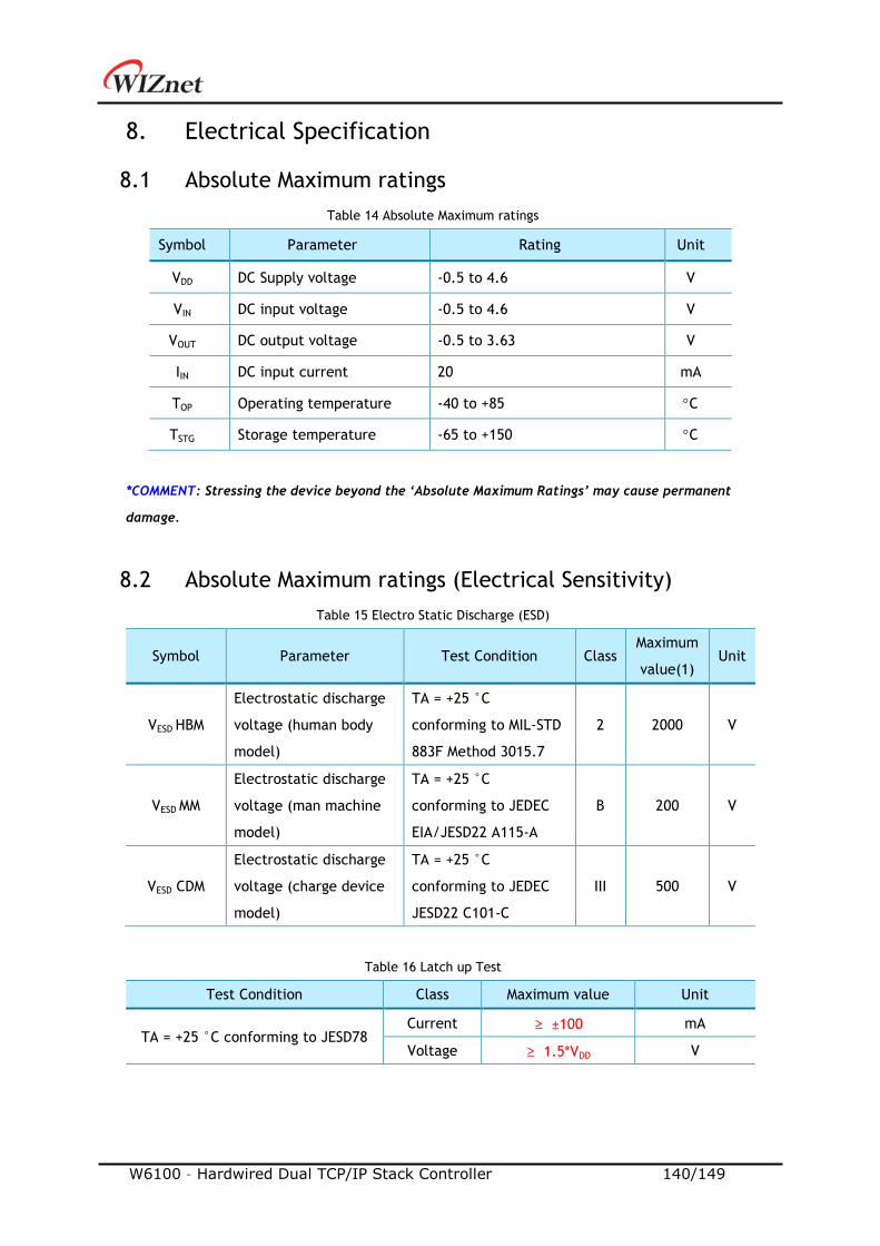
W6100 – Hardwired Dual TCP/IP Stack Controller 140/149
8. Electrical Specification
8.1 Absolute Maximum ratings
Table 14 Absolute Maximum ratings
Symbol Parameter Rating Unit
VDD DC Supply voltage -0.5 to 4.6 V
VIN DC input voltage -0.5 to 4.6 V
VOUT DC output voltage -0.5 to 3.63 V
IIN DC input current 20 mA
TOP Operating temperature -40 to +85 C
TSTG Storage temperature -65 to +150 C
*COMMENT: Stressing the device beyond the ‘Absolute Maximum Ratings’ may cause permanent
damage.
8.2 Absolute Maximum ratings (Electrical Sensitivity)
Table 15 Electro Static Discharge (ESD)
Symbol Parameter Test Condition Class Maximum
value(1) Unit
VESD HBM
Electrostatic discharge
voltage (human body
model)
TA = +25 °C
conforming to MIL-STD
883F Method 3015.7
2 2000 V
VESD MM
Electrostatic discharge
voltage (man machine
model)
TA = +25 °C
conforming to JEDEC
EIA/JESD22 A115-A
B 200 V
VESD CDM
Electrostatic discharge
voltage (charge device
model)
TA = +25 °C
conforming to JEDEC
JESD22 C101-C
III 500 V
Table 16 Latch up Test
Test Condition Class Maximum value Unit
TA = +25 °C conforming to JESD78 Current ≥ ±100 mA
Voltage ≥ 1.5*VDD V
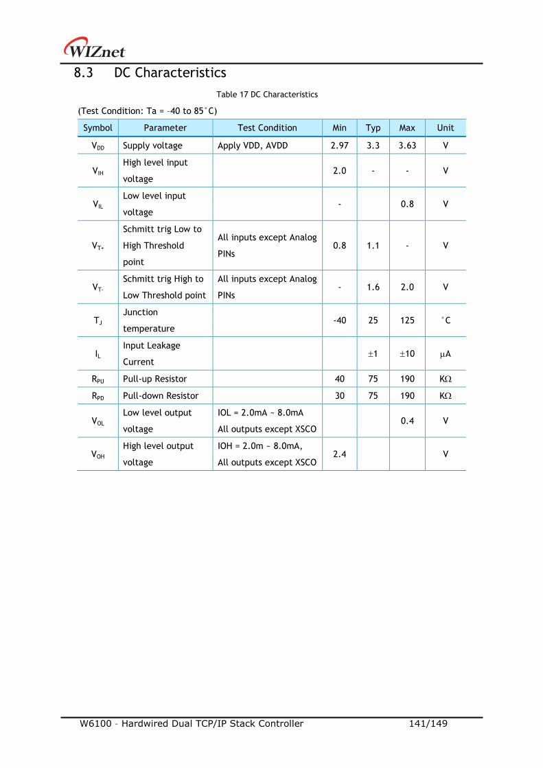
W6100 – Hardwired Dual TCP/IP Stack Controller 141/149
8.3 DC Characteristics
Table 17 DC Characteristics
(Test Condition: Ta = –40 to 85°C)
Symbol Parameter Test Condition Min Typ Max Unit
VDD Supply voltage Apply VDD, AVDD 2.97 3.3 3.63 V
VIH High level input
voltage 2.0 - - V
VIL Low level input
voltage - 0.8 V
VT+
Schmitt trig Low to
High Threshold
point
All inputs except Analog
PINs 0.8 1.1 - V
VT- Schmitt trig High to
Low Threshold point
All inputs except Analog
PINs - 1.6 2.0 V
TJ Junction
temperature -40 25 125 °C
IL Input Leakage
Current 1 10 A
RPU Pull-up Resistor 40 75 190 K
RPD Pull-down Resistor 30 75 190 K
VOL Low level output
voltage
IOL = 2.0mA ~ 8.0mA
All outputs except XSCO 0.4 V
VOH High level output
voltage
IOH = 2.0m ~ 8.0mA,
All outputs except XSCO 2.4 V
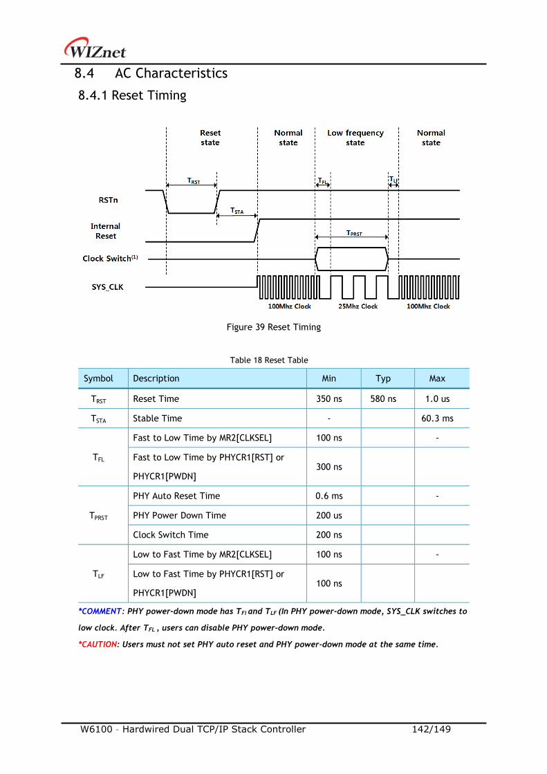
W6100 – Hardwired Dual TCP/IP Stack Controller 142/149
8.4 AC Characteristics
8.4.1 Reset Timing
Figure 39 Reset Timing
Table 18 Reset Table
Symbol Description Min Typ Max
TRST Reset Time 350 ns 580 ns 1.0 us
TSTA Stable Time - 60.3 ms
TFL
Fast to Low Time by MR2[CLKSEL] 100 ns -
Fast to Low Time by PHYCR1[RST] or
PHYCR1[PWDN] 300 ns
TPRST
PHY Auto Reset Time 0.6 ms -
PHY Power Down Time 200 us
Clock Switch Time 200 ns
TLF
Low to Fast Time by MR2[CLKSEL] 100 ns -
Low to Fast Time by PHYCR1[RST] or
PHYCR1[PWDN] 100 ns
*COMMENT: PHY power-down mode has TFI and TLF (In PHY power-down mode, SYS_CLK switches to
low clock. After TFL , users can disable PHY power-down mode.
*CAUTION: Users must not set PHY auto reset and PHY power-down mode at the same time.
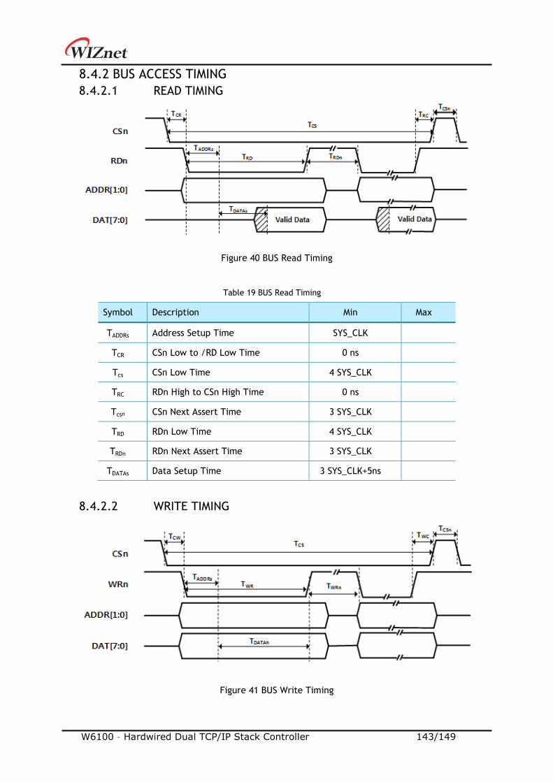
W6100 – Hardwired Dual TCP/IP Stack Controller 143/149
8.4.2 BUS ACCESS TIMING
8.4.2.1 READ TIMING
Figure 40 BUS Read Timing
Table 19 BUS Read Timing
Symbol Description Min Max
TADDRs Address Setup Time SYS_CLK
TCR CSn Low to /RD Low Time 0 ns
Tcs CSn Low Time 4 SYS_CLK
TRC RDn High to CSn High Time 0 ns
Tcsn CSn Next Assert Time 3 SYS_CLK
TRD RDn Low Time 4 SYS_CLK
TRDn RDn Next Assert Time 3 SYS_CLK
TDATAs Data Setup Time 3 SYS_CLK+5ns
8.4.2.2 WRITE TIMING
Figure 41 BUS Write Timing
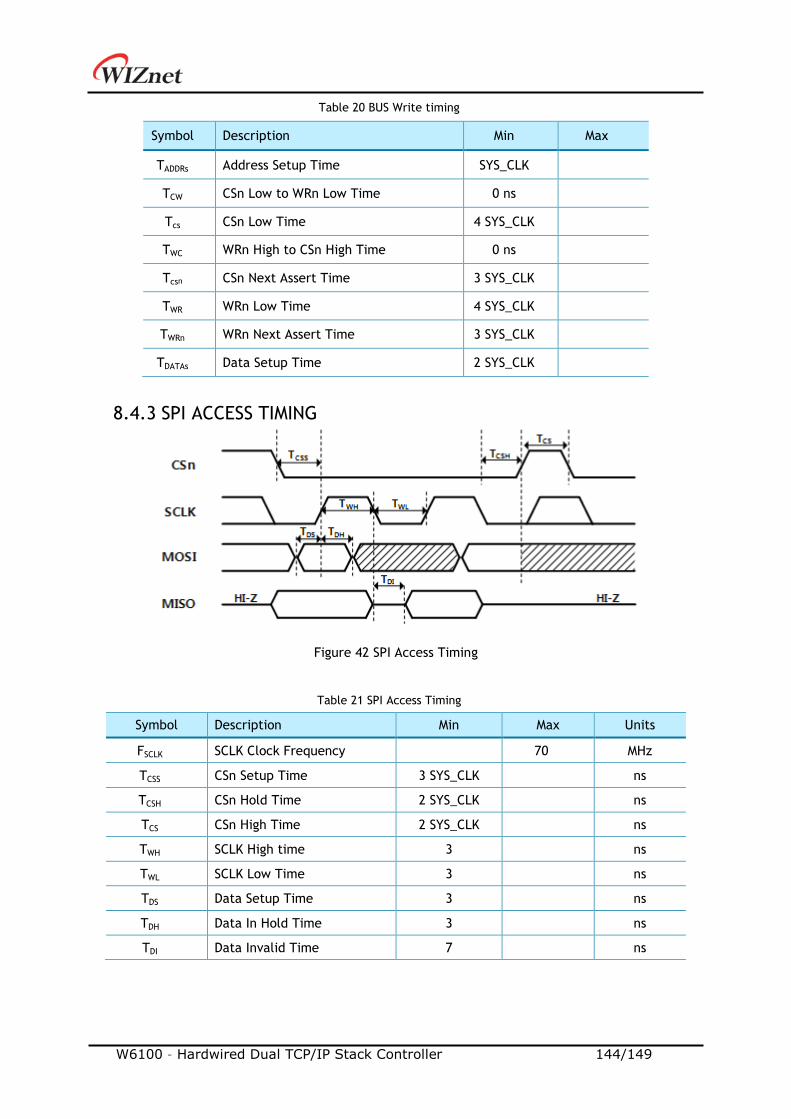
W6100 – Hardwired Dual TCP/IP Stack Controller 144/149
Table 20 BUS Write timing
Symbol Description Min Max
TADDRs Address Setup Time SYS_CLK
TCW CSn Low to WRn Low Time 0 ns
Tcs CSn Low Time 4 SYS_CLK
TWC WRn High to CSn High Time 0 ns
Tcsn CSn Next Assert Time 3 SYS_CLK
TWR WRn Low Time 4 SYS_CLK
TWRn WRn Next Assert Time 3 SYS_CLK
TDATAs Data Setup Time 2 SYS_CLK
8.4.3 SPI ACCESS TIMING
Figure 42 SPI Access Timing
Table 21 SPI Access Timing
Symbol Description Min Max Units
FSCLK SCLK Clock Frequency 70 MHz
TCSS CSn Setup Time 3 SYS_CLK ns
TCSH CSn Hold Time 2 SYS_CLK ns
TCS CSn High Time 2 SYS_CLK ns
TWH SCLK High time 3 ns
TWL SCLK Low Time 3 ns
TDS Data Setup Time 3 ns
TDH Data In Hold Time 3 ns
TDI Data Invalid Time 7 ns
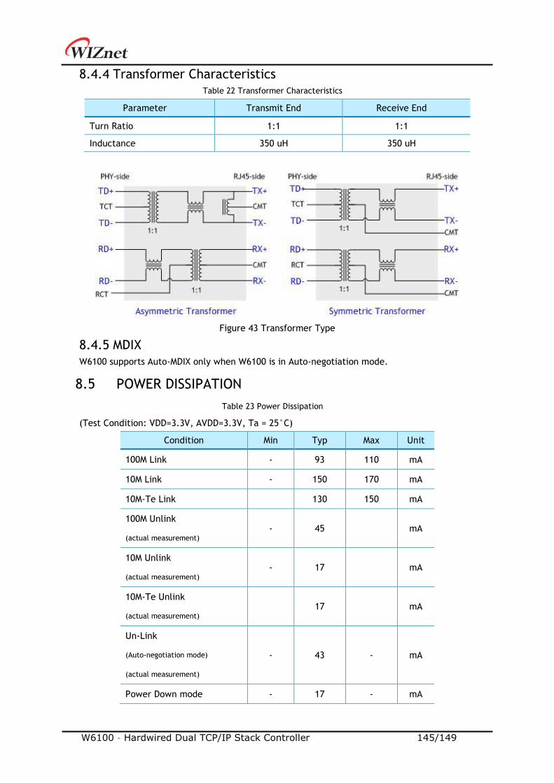
W6100 – Hardwired Dual TCP/IP Stack Controller 145/149
8.4.4 Transformer Characteristics Table 22 Transformer Characteristics
Parameter Transmit End Receive End
Turn Ratio 1:1 1:1
Inductance 350 uH 350 uH
Figure 43 Transformer Type
8.4.5 MDIX
W6100 supports Auto-MDIX only when W6100 is in Auto-negotiation mode.
8.5 POWER DISSIPATION
Table 23 Power Dissipation
(Test Condition: VDD=3.3V, AVDD=3.3V, Ta = 25°C)
Condition Min Typ Max Unit
100M Link - 93 110 mA
10M Link - 150 170 mA
10M-Te Link 130 150 mA
100M Unlink
(actual measurement) - 45 mA
10M Unlink
(actual measurement) - 17 mA
10M-Te Unlink
(actual measurement) 17 mA
Un-Link
(Auto-negotiation mode)
(actual measurement)
- 43 - mA
Power Down mode - 17 - mA
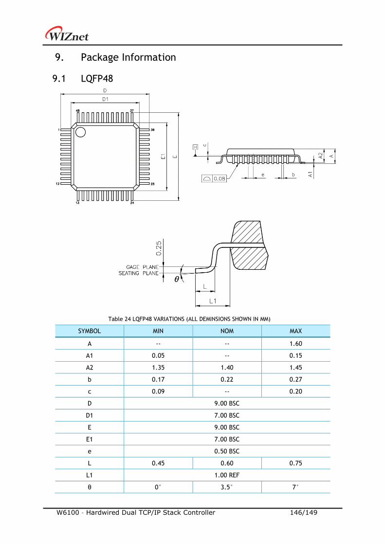
W6100 – Hardwired Dual TCP/IP Stack Controller 146/149
9. Package Information
9.1 LQFP48
Table 24 LQFP48 VARIATIONS (ALL DEMINSIONS SHOWN IN MM)
SYMBOL MIN NOM MAX
A -- -- 1.60
A1 0.05 -- 0.15
A2 1.35 1.40 1.45
b 0.17 0.22 0.27
c 0.09 -- 0.20
D 9.00 BSC
D1 7.00 BSC
E 9.00 BSC
E1 7.00 BSC
e 0.50 BSC
L 0.45 0.60 0.75
L1 1.00 REF
θ 0° 3.5° 7°
W6100 – Hardwired Dual TCP/IP Stack Controller 147/149
NOTES:
1. JEDEC OUTLINE:
MS-026 BBC
MS-026 BBC-HD (THERMALLY ENHANCED VARIATIONS ONLY)
2. DATUM PLANE H IS LOCATED AT THE BOTTOM OF THE MOLD PARTING LINE COINCIDENT WITH
WHERE THE LEAD EXITS THE BODY
3. DIMENSIONS D1 AND E1 DO NOT INCLUDE MOLD PROTRUSION. ALLOWABLE PROTRUSION IS 0.25
mm PER SIDE. DIMENSIONS D1 AND E1 DO INCLUDE MOLD MISMATCH AND ARE DETERMINED AT
DATUM PLANE H.
4. DIMENSION b DOES NOT INCLUDE DAMBAR PROTRUSION.

W6100 – Hardwired Dual TCP/IP Stack Controller 148/149
9.2 QFN48
Table 25 QFN48 VARIATIONS (ALL DEMINSIONS SHOWN IN MM)
SYMBOL MIN NOM MAX
A 0.70 0.75 0.80
A1 0.00 0.02 0.05
A3 0.203 REF
b 0.20 0.25 0.30
D 7.00 BSC
E 7.00 BSC
e 0.50 BSC
D2 5.25 5.30 5.35
E2 5.25 5.30 5.35
L 0.35 0.40 0.45
K 0.20 -- --
LEAD FINISH Pure Tin V PPF X
JEDEC CODE N/A
NOTES:
1. ALL DIMENSIONS ARE IN MILLIMETERS
2. DEMENSION B APPLIES TO METALLIZED TERMINAL AND IS MEASURED BETWEEN 0.15mm AND
0.30mm FROM THE TERMINAL TIP. IF THE TERMINAL HAS THE OPTIONAL RADIUS ON THE OTHER
END OF THE TERMINAL, THE DIMENSION b SHOULD NOT BE MEASURED IN THAT RADIUS AREA.
3. BILATERAL COPLANARITY ZONE APPLIES TO THE EXPOSED HEAT SINK SLUG AS WELL AS THE
TERMINALS.
W6100 – Hardwired Dual TCP/IP Stack Controller 149/149
10. Document Revision History
Version Date Descriptions
Ver. 1.0.0 1FEB2019 Initial Release
Copyright Notice Copyright 2019 WIZnet Co., Ltd. All Rights Reserved.
Technical Support: https://forum.wiznet.io/
Wiki : https://wizwiki.net
Sales & Distribution: mailto:[email protected]
For more information, visit our website at http://www.wiznet.io/