Embed Size (px)
Citation preview
VOL. 9 ~o. 2, p. 33-6~ • 1947
Philfps Te~hnicaI'DEÄLING WITIi TECHNICAL ,PROBLEMS.
RELATING TO ,THE PRODUCTS~ PROCESSES AND .INVESTIGATIONS OF
N.V. PBILIPS' GLOEILAMPENFABRIEKEN·.'
·EDITED BY THE RESEARCH LABORATORY OF N.V. pmî:.Jps' GLOEILAMPENFABRmKEN, EINDHOVEN, HOLLAND. , . . ' ,~ . ' '\'
• I
A NEW ELECTRON MICROSCOPE WITH CONTINUOUSLY VARIABLE. . " .' MAGNIFICATION - , . , '
Jby J. B. le POOL;E. 621.385.833..
- .-
Several articles concerning electronic riû~roscopes will be published in this ~eriodical.In this first article of the 'series' some characteristics of ordinary optical microscopes are \'reviewed. The wave nature of light sets a limit to the resolving power: The .smallest distancebetween two distinguishable details is 1000ÁngstrÖni units'with the best opticalmicroscopes.A significaht improvement in resolving power is obiiiined by using electron beams instead
, of light. The principle of the electron microscope is first explained with particular reference',to the focusing óf electron-beams by magnetic lenses. A description is then given of a..
" new electronmicroscope now in use at the Institute for Electron Microscopy at Delft.'. \ ", ... . ~The advantages of the new construètion over previous models are explained. The resolvingpower amounts to about 25 Á and the magnification is continuously variable from 1000to 80 000 times. With this instrument it' is also possible to get an electron" diffraction
. pattern of a part of the specimen which has first been studied electron-optically, whichoffers the advantage of ~n easier id~ntification of the materials which are being investigated.In conclusion several applications of electronic microscopes are mentioned.
~ "
In r~cent years investigations hav~ been carried ,èentrates' a be~~' of light on the 'object~Jurtliè; an"out in '\~any countries with.microscopes where use: \ objectivo .whioh forms an .enlarged intermediate .
. is made of electron beams. This has also been the, image of the Object, and an ocular Withwhich this.• case in the Netherlands, especially at the Technical image is observed. The total magnification is foundUnivérsity at D,elft'and in the. Philips Laberatory by multiplying the enlargement ~f the objective~.
. 'at Eindhoven. It is our intenii~n to devote several h'y'thát of the ócular.· .'''- articles in this periodical to that subject. .In this It is easy to see that the wave nature of light sets'first article a description is given of the electron a limit to the resolving power, i.è. to the small-. "...microscope. that was construèted by the_author est distance between two details which can .just
',' for the Institute for Electron Microscopy at Delft, he distinguished from.each other. When.a beam of_' which is under his-dire~tion. This instrument was light rays strikes an' objeet they will be' stopped
c completed in 1944and was then used for onemonth. by the non-transparent parts. rhe transparent parts. It was then taken apart and the parts were hidden' transmit the rays, which, when a lens is' placed in- to prevent their ....being carried off by the enemy. their path, converge again in-the plane of the image.•. Immediately .afte~ the liberatión the instrument If, however,_-die opening between two non-trans-was assembled a~d taken into use again. parent parts is of the order-of magnitude of theAs an introduetion to-the description of the new wavelength of the light used, the light is strongly'
. microscope we shall first rèview several charac-' diffracted' and scattered at the other side of the • -.teristics of the optical micr oadop e for purposes object over a wide angle. Because only a small part , .of comparison, and then- deal briefly with the of this beam reaches the lens thè part of the imagegeneral principles upon which the' functioning of . ccrreaponding to the opening will still remain dark.the electron microscope is based. . In this way it can bè understood that' the resolving
. power'of an optical microscope is of the same orderThe optical ~cros~pe . " of magnitude as the wavelength of the lighi used.It is a matter of general knowledge that a light. This wavelength of visible light lies between 0;8 .(.1.
microscope contains a eondeneer lens which con-' and 0.4 (.1." .',
..
,
:. ,
.'
34 PHILIPS TECHNICAL. REVIEW •. ..,. ,1~47 '
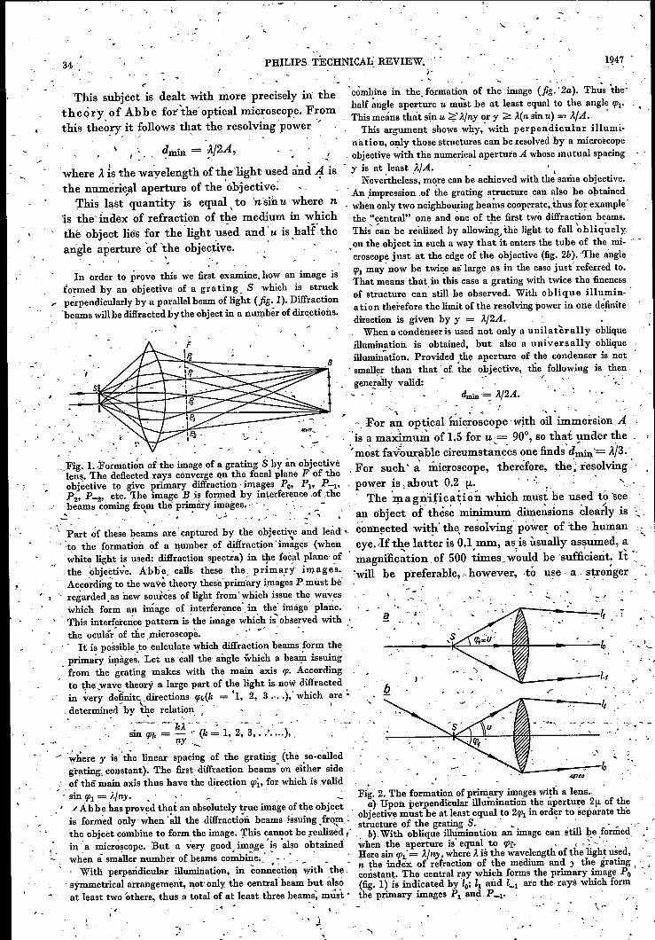
'_ I': .combine in the.formation of the image (jig.' 2a). Thu's 'the:half ~ngle aperture u mUStbe at least equal to the angle f{Jl"
This means thát sin u ;;;{Ä/ny or y ~ Ä(n sin 11) = NA. 'This argument shows why: with perpendicular illumi-
n a ti on, only those structures can be resolved 'by a microsec pedmin = .).j2A, ',. ,.. .:. ' objective with the numerical aperture A whosemutual spacing
.where .itis the wayelength of thelight used and A is, - y is at ,least AlA. , ,the nunûîric,alaperture of the .óbjective. . Nevertheless, m~re can be achieved with the same objective.
, An ,impression .of the grating structure can also be obtained'l'his ,l~st quantity is equal \to 'nsinu where n . when only two neighbouring bea~s cooperate, thus for example'
'is the' index of refraction of the medium in which the "central" one and one of the first two diffracti~n beams.thè object lies for thelight u;ed andu is ha,l:f.the This'~an be realized by allowing ...the light to faU'obliq~ely.angle aperture 'of t,he objective. " .on the object in such a way that it enters the tube of the mi- ~ .
.croscope just at the edge of the objéctive (fig. 2b). The angle .!PI may' now be twice as' large as in the 'case just' referred to.That means that in this case a grating with twice the finenessof structure can' still be observed. With oblique illumin- .a tion therefore the limit of the resolving power in one définitedirection is given by y = Aj2A. .When a condènser is used not only a unilatèrally oblique
illumination is obtained, but also a un iv.er s a Il y oblique~t~b:~~;::;~~~:::~~~1Bill~tion. Provided the aperture of the condenser is nott. . smaller than that. of Îhe objective, the following is thengenerally valid: ' ,/ "
dmin'~ ).j2A.
'-. '-'kÄ-~ -.' --'- ,._.'sin !pk = - "(k = 1, 2, 3, .-.' .... ),~, - ~ ~y '_ <
~here y is' the linear spacing of the gratirig (thè so-called, grating, constant). The first diffraction beamson either side: of thê main axis thus have the direction !pi, for which is .valid/ :'sin f{J1= AJny. ,." . _ Fig. 2. The formation of primacy images with a lens.. ', "Àbbe 'has proved that an absolutely true image of the object ' a) Upon perpendicular illumination the aperture 2fJ.of theis forme<l onI,y when' ill the difIracti;:ii beams issuing ,trQm,.: " objective must be at least equal to 2f{J1 in order to separate the
, structure of the grating S. ,'. ," • _ 'the object combine to form the image. This cannot be realieèd / " b). With oblique Illumination an image can still he .formedin 'a microscope. But a very good image 'is -also obtained when the aperture is' equal to !p.f· ., - ~, '. 'when à smiller number of beams co~hîe •. ' . , '.' , Here sin !Pl'= Ä/ny, where Ä is the. wavelength of the 'light used,
. .' • _ • •• ' p •• - n the index of .refraction of the medium and y the grating, Witlî perpendicular illumination, in connection with the, constant. Thé central ray which forms the primary image Po ', symmetrical arrangement, not-only the central beam but also (fig. 1) is indicated by lo; II and Cl are the rays which format least two 'others, thus a total of at least three beams; mûst· the primary images Pi an~,P -1'
This subject is dealt with more precisely in thetheory. of Abbe for'the' optical microscope.Fromthis theory it follows that the resolving power '
• ~ x • ~.
In order to prove this we first examine. how an image isformed by an objective of a grating, S which is struck
" pe-rpendicularly by a parallel beam of light (jig. 1). Diffraction'beams will be diffracted :by~e object in a number of directions,
. ,"Fig. 1..Fo;mati~n of the image of a grating S by an objectivèlens. 'lhe deflected rays converge on the focal plane F of theobjectivo to give primary diffraction images' Po, Pi' P4.' 'P2, P-2, etc. The image B is formed by interference .of'thebeams coming from the primary images." , . ."... ' '< ..# "~ .... ~ .• ..: '
Part ~f these beams are' captured by the objective and lead'" _."to' the formation of a number of diffraction "images (when,~hite light is used: difîraction spectra) in the focal plane ~fthe objective. Abbe. calls these the prim:ari imag es.,Acc6~ding to the wa,v~theory these primary images P must hé
-; regarded as new sourcea of light from'which issuethe waveswhich fo~m an image of interferencedn the' image plane.:
: Tbis interfei:e-O:cepattern is the image which is' observed with .the ocular~of the microscope. . .' r': -'. ". It is possible to .calculate which diffraction beams form theprimary imàges, Let us èall the angle which a bear? issuingfrom the grating makes with the main 'axis rp. Accordingto thewave theory a large part of the light is.now diffractedin very defimt<:.directions f{Jk(k = 'I, 2, 3,- .. ); which are ~- \determined by ~e relation ; . I
"
"
";'
'-"1 " '"I.
-,For an optical mîcroscope with oil immersion A-is a maximum of1.5 for u = 90°,so thai under the"most fav"our:ablecircumsta~c'esonefinds'd~' - .it/3..For such';' microscope, therefore, the; resclving"power is,about 0.2.11-' . '-: , .. ., ': ",", The 'l!1agn#ica~iónwhich must he used tó 'see
,., , • ,.t.
an object of these mimmum dimensions clearly is ...,'connected with'the, resolving power.of :the humaneye.Ht4,e latter is O.l.mni~asis usually assumed, a -,magnification of 500 times. would be sufficient. It-:'will he preferahle.>however,' .tó use· a ~~ro:rÎger',
.-..'.
.;'- ..
., .
, \
magnification than strictlynecessary in order 'not. Sinée With electron beams wav~lengths are thus't~ tire the' eye too much and to make every detail rea'ch~d which are, for 'exampl~, ,100 000 times aseasily visible. A' magnification of 1000 x'or 1500 X small ~s those-oftlÎe lightused for ultra microscopy, ' '
, is usually used. Creater magnifications are in' general theoretically an .increase in the resolving po~er ~Y :,' ~flittle use-with án optical microscopé.', . . the same factor, is possible when the image' of an.. The only- way of improving thê resclviag.power : object-is formed with electron rays. This does notwhen, the Ii.u~ericál .aperture is á maximurn is to mean that this is a practical possibility. In the first·, ~use light of á shorter wavelength:, The use of. micro- , place _itis necessary thatit should actually be possible
,', Scopès for u It r avv.io l e t light is based on this fact., to form an image with electron rays, and, in the, . , Since glass does not transmit ultra-violet rays these second'~place,. if that .can b~ done, the resolving
, instruments .must he equipped with quartz lenses. . power attained, still, depends upon the' quality .öf ~,In this way' -the resolving power-Ja increased h-y::- , the, lenses to be used for the image-formation. In. ~. factor 2. ' '".' ,:' .' • , ' .: " the' ca~e of X-ray~, which also possess the yery' I
:- Fo~ the distance between ,tw9. details which can. ,short wavelengths mentioned and therefore promisejust be seen separately a limit of 0.( (l. or 1000. theoretically.;. a high resolving power, the fi~st!,' ",flngströ~~ is then found. In many modern investi-: " condition is 'no(' satisfied; no medium jis known v.' ~.:
. ~ gations, however, therf:?-is need of an' mstrttment which has ~ refractive m'dex for X~ráys' appreciably" '~':with a stili ¥ihér,_ resolving p~w~r.'·' ' different from unity, Therefore it is impossible to ~-
c " • " make "x!-ray lenses". "Electron rays on the,' other ''Prin"ciple of. the electron 'riûcros~o~e " ., hand can be _refracted .and 1'ocused by, means of'
An important improvement in the resolving power magnetic, or electrostatic fields> al{d thus án image' r.
" is obtained by usipgeleetron beams ilÎs~ead of light. '. can be obtained. Thè ,ter_¥linology of the optical, In 1924'Louis de Broglie announced that a microscope has beentaken ~ver and one speaks of
.. ..., .-....... I' . ~,
,. .wavenature must be assigned to moving electrons. .m a g a e t ic , and e l e c tr o's t a tic len s e's, The', Experimentally 'this was confirmed shortly -after- . 'unavoidable errors of, these' lenses, as it ~loser' '.w~rd~'by'interferenée experimeûts carried out'hy the theor~tical co~sidei~tion shows,' make it· ir'npo~sihl~Americ~~ inveSjigators I?aviss~~,"~d'Gernie-r.' !o obtain anywhere the limit '4?f't~~ resolving'The wavelength of the' electron depends upon 'its power that \vould be' expected on .the basis of. t~e ,velocity. The greater the velocity the shorter the' wàvel~ngth:With an ~éceleràting voltage ofI50 kV,wav~length. According to 'de Bno gl ie the wave na- , it will not pe 'possible to go farther thàn-5 k. In' '-
, ture of an. ~lectron is characterized hy -~ .;' . 'practice, at this voltage, a resolving power of 15 ..to';' " rh" '~;" ' " " . 3Ó Á has already been rea~hed. A magnetic eleétioh
,~", .' • • A -, ' ' léns is' ä.short éoil'which thus gives a uon-homogen-':" ,~. " ,m'!!,.... - - 5' " \' ' ' • . ~QUS ~agnetic field with rotational ,syni:rn:etry'-
, . where, h is P)anck',s consta~t, m the m'a~s and v' .An electrostatic lens IS usually some 'co~bination• C the velocity of the electron, • " J • • '':" ' or other of electrode's ,which gives an electrostatic', '_ When ~n electron with the ch~~ge e passes t~ougIl .non-homogèneous field;: likewise with 'rotational~_.a potential,differenc~ 'V its kinetic energy is '.. symmetry. In both casesthe field often has, more;',_ '". - -.:: ; '~/;' ',. 2 . V. . ' over, 'a-plane of ~ymmet.ry p'etpe~dicular to. the axis~, mv = e . . .. , .
2 ., 'l " of symmetry. Concepts such af? object distancè. a"from which It follows thá~' '; ," and image distance i; focal distance j and power l/J . f '
of a lens are also'; defined in electron-optics in thesame 'way as in ordinary optics. The relatiorr between "a, b an-df here is also given by' ~ " " ..
•~ ... 'I 1 1-, . - + - ='-. '.
'" ,à- b -i
.' ~'-,..
- AN ELEÇTRON;MICROSCOPEVOL 9, No. 2."
, ./
,",- 'y2eV" - . y-j;2.-. ·v:_ --.- and Ä. =. --"., .-. m..'·~' 2meV
When we "suhstitute the known values in "this:h = 6.6; X 10-27; m =~9!1 X' 10-:-28; e __,4.8 X 10-:;-10,e.s.u., 'expressing Vin volts, we obtain' '
. -:/, y150 8" ", 12.3. A" . ''Ä. '= -- ·10- cm ='= _ ••
V, ,1 V' ". , • f
. ',.
One also speaks oft hin lenses, meaningJenses so'. constructed that-the thi~kness of th~ region within, which the influence 0:Q. the path of ámoving electroncannot be disregarded is small _compa,~edwith theobject and image, distance. -For' the, power of' athin lens' in -the electrostatic case the followinghólds:
(I)
Correspondiug to electrons of an energy of 159 kV,.vwe therefo~e have waves of matter óf about 0.03 A,=- 3',X· IO-~o.cm', thus a wavelength of the order of .ni~gnitude of hard X-rays. ' _
, . ~..... ,
, .,
35 -
, '
(2)
l
"
36 P~ILIPS TECHNIÇAL REVIEW 1947
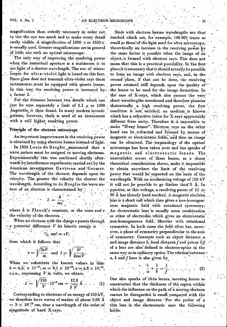
. Thefact that it is possible to focus -electron rays is by no,means aelf-evident," especially in the' magnetic case 1Vherethe force acting on the electron ,depends upon', the •vel?cityof the latter; We shall prove this below l), för the magneticlens in a special case, namely for electrons which start froma point ofthe axis and follow trajectories in the neighbourhoodof the axis (paraxial rays).' We wish to' show that all the elec-
" trens issuing from a point Rl on the axis which lies in front On the basis otfig. 4 ~e shall ~ow calculate this H" In.theofthe coil.und whose trajectories make a small angle a with the figure A1B1 and AzBz represent two circular cross sectionsaxis, converge again at the other side of the lens ata point Pz' with the radius T taken perpendicular to the axis ~f the coil
': on the axis. In fig. 3 the tr!_ljectoryof one of these electrons , at the points. Xj_ and ~2" The .~Xial 'co~pon:ents" gf .the 'field, through the field of the lens is represented diagrammatically. strength at Xj_ and xa we. shall' call Hi and Ha respectively. 'We call its distance fró~ the. axis r and it~ velocity v. The The number of magnetic lines of force 'passing through the,'small'radial velocity of the electron _!hen amounts initially cross section AaBa but not through A1E1 is mZ(H2_:_H1). 'to va. The distances from P1 and Pa to the niiddlè~of the lens This is the number of lines of force cutting the cylindricalare 'respe~tively ~ 'ana b. Fro~ the fact "that we :<;onfin~our- " surface with the ~area 2m(xz"":"'Xj_). The jrverage ;alue' of theselves to paraxial rays it also follows that the- maximum radial magnetic fo~ce is therefore Hr = T(Hr-H1)/2(~2-Xj_),dist~ce TO to the axis is so small that at that distance thè axial from-which, upon passing over to an infinitésimal distance,
" component H of the magnetic fi~ld'is practicçlly the àame as one finds ~that ". ~~• 'on 'the axis.' , -r ':' ',,' ',' , ~ '\_ " • ' , I T dH, Hr=--'- -;As soon as the electron enters the magnetic fieldit is deflected ,I .. I 2 dx "
laterally. It will then travel along a helix aro~nd the axis:with a-gradually changing radius. The éhangein the radius,which-amounts to 'a movement of the electron towards theaxis, is caused by a forée 'which' is, the .r~sult ot:.the axialmagnetic field and the angular ve!?city, with respect to the,axis. This angular velocity rp can be qalculated in the followingway. The change per unit of time in the impulse, moment of
. ,
+0>1 ,,1 - f' 1 (dV)2 . ,f ' 8 VVo iVa dx ~
, - ,-co "
and in the' magnetic case: ~
1 :-'6'·'f+O> - "-= -,- H2dx, .
,,- .f 8m Vo ~,
-;
-co ,
where the x-axis is the axis of symmetry, Vo is theaccelerating potential, V'the electrostatic potentialon the axis .and H the magnetic field 'on the axis.
, The 'magnifi~ation is' given in ~oth "cases by us:
"
, _(
\
_'
"'.
,r
48897
Fig. 3. Diagram of the path of an electrón In a thin magneticlens: projection on a plane through the axis of symmetry (left)
.. and projection on a plane perpendicular to this axis (right).The linea-of forée drawn characterize the magnetic afield ofthe lens. The electron leaves the axis- at P1 and reáches itagain at P 8' The distances 'from P 1 and Pa _to the. middleplane of the lens are à and b, respectively; the angles which.'the ray make with the axis at P1 and P2 are a and (Jo respec-tively. The maximum distance of tile electron from the axisis TO' ' " "
1) A similar proof. may be found: also in .(1.. Bo uwer s,Physica 4, 200, 1937.
(3)
, ,the electron: with respect to the axis is equal to the momentof the ~orentz force,with respect, to the axis, Hence '
d ' ,-dim T2 q., ='7 T (e Vr H -\ e v Hr); -:. . (~)
where v, is the radial velocity and Hr the radial magneticfield (calculated as positive in the direction ~of th~ axis),Here v cos a is replaced by v.
(4)
, At
Fig. 4. The magnetic lines of force ,ID a small cylinder whosêaxis coincides with the axis of symmetry of the magneticlens. The cylinder with the radius T is shown in C!:,osssection;A1B1 and A!B2 represent two circular cross sections of thecylinder perpendicular to its axis at the 'points Xj_ and X2'
The axial components of the field strength at Xl and Xs areHl and Hz respectively. -
(6)
" The above equation of motion (5) thus becomes-' , ~ .
,i r~' =~, (T ~' :u ~ ê dH dx)" .dt.':IP m dt, 2dxdt
, .The expression between parentheses in the second member
is nothing/else than the differentlal quotient of the producti/2 T2H with respect to time, so that we obtain '. '" _.. .~.
d e d '" di T~ q., ~ ;;i di 1/~T2 K.
From this it follows that'
(7)
We see, therefore, that the angular vefocity of theelectron 'is propottion:al to the axial magnetic field., Itbecomes zero as -soon as the electron has "passed through thefield of the coil. The electron cannot pass the axis, Behindthe coil it moves in a plane which passes through the axisand the~, ~hê'n !he fi~ld of the coil is strong enough, i~ muststrike the axis due to its in~ardly directed velocity. •In order to find the inwai:dly <!!rected acceleration o(the'
electron it must b~ notèd that a centripetal force mrpr~ wouldbe necessary to keep the electron at' a constant distance T
fro~ the axis. But the' axial magnetic field and the l~teratvelocity together-cause an in'rilrdly directed Lorentz forêe:
-Kr = eq.,'rH., \
VOL. 9, No. 2 AN ELECTRON MICROSCOPE 37
The resulting acceleration is therefore
'r = Krim + qh,or, according to (7)
.• e2r H2r = - 4m2 •
IFor the case of a thin lens, thus where the field acts only
over a short distance, r may be considered a constant ro.Equation (8) can then easily be integrated. By setting dt = dx/v- which is permissible, because we have confined ourselvesto rays in the neighbourhood of the axis - we find that
+'"._vro e2ro r 2r - - - 4- 2 H dx . . . . .
a m " ,
Due to this velocity the electron will reach the axis after thetime 1: = rol;. Since it is found from fot mula (9) that thistime is the same for all electrons issuing from a point PIon the axis, they are indeed all focused at the same point P2,
which concludes the proof.For a thin lens it is now easy to prove formulae (4) and (2).
Just as the electron has the radial velocity; = vro/a beforeentering the magnetic field, thus between PI and the lens.after leaving the magnetic field, thus between the lens and P2,
it will have the radial velocity
• vror=-b'
b being the image distance, i.e. the distance between P2 andthe lens. When this is substituted in (9) we find that
+'"1 1 e2 fa + b = 4 m2 v2 H2 dx,
which corresponds to (2) when the expression (4) is sub-stituted for I/j and 1/2mv2 = eVo is taken into account.
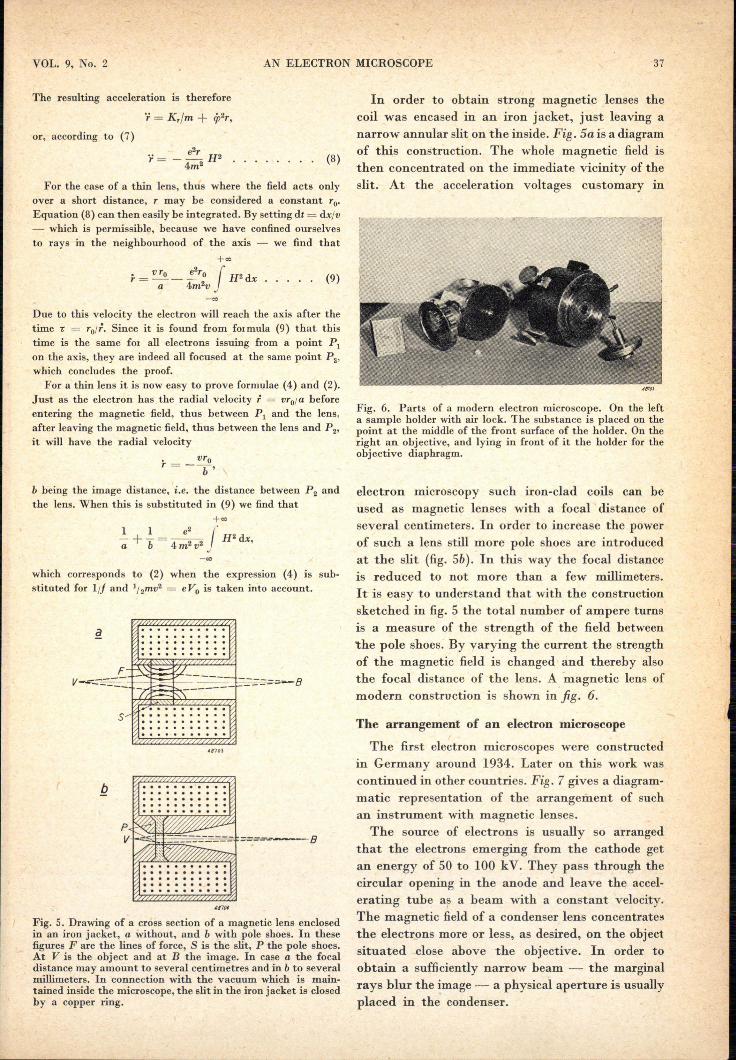
............. .. .. .. .. .. .. .. .. .. .......................... .. .. .. .. .. .. .. .. .. .... .. .. .. .. .. .. .. .. .. ..F
V-=::~~4-~-~~--
5.................. Ilo •.. .. .. .. . .. .. . ..... .. .. . . . ..
4(/703
................... .. .. .. .. .. .. .. .. .. ..................... .. .. . .. .. .. .. .. .
.............................................. .. .. .. .. .. .. .. .. .. .... .. .. .. .. ... . .. .. ..
Fig. S. Drawing of a cross section of a magnetic lens enclosedin an iron jacket, a without, and b with pole shoes. In thesefigures F are the lines of force, S is the slit, P the pole shoes.At V is the object and at B the image. In case a the focaldistance may amount to several centimetres and in b to severalmillimeters. In connection with the vacuum which is main-tained inside the microscope, the slit in the iron jacket is closedby a copper ring.
(8)
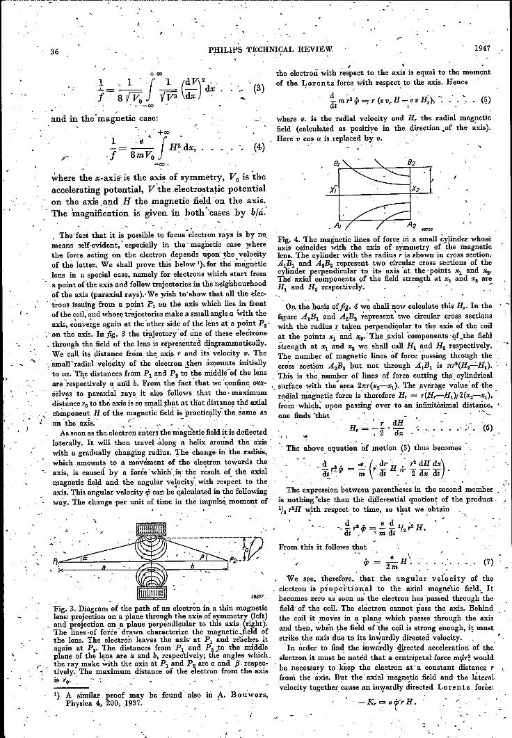
In order to obtain strong magnetic lenses thecoil was encased in an iron jacket, just leaving anarrow annular slit on the inside. Fig. Sa is a diagramof this construction. The whole magnetic field isthen concentrated on the immediate vicinity of theslit. At the acceleration voltages customary in
(9)
4~71)j
Fig. 6. Parts of a modern electron microscope. On the lefta sample holder with air lock. The substance is placed on thepoint at the middle of the front surface of the holder. On theright an objective, and lying in front of it the holder for theobjective diaphragm.
electron microscopy such iron-clad coils can beused as magnetic lenses with a focal distance ofseveral centimeters. In order to increase the powerof such a lens still more pole shoes are introducedat the slit (fig. Sb). In this way the focal distanceis reduced to not more than a few millimeters.It is easy to understand that with the constructionsketched in fig. 5 the total number of ampere turnsis a measure of the strength of the field between'the pole shoes: By varying the current the strengthof the magnetic field is changed and thereby alsothe focal distance of the lens. A magnetic lens ofmodern construction is shown in fig. 6.
The arrangement of an electron microscope
The first electron microscopes were constructedin Germany around 1934. Later on this work wascontinued in other countries. Fig. 7 gives a diagram-matic representation of the arrangement of suchan instrument with magnetic lenses.The source of electrons is usually so arranged
that the electrons emerging from the cathode getan energy of 50 to 100 kV. They pass through thecircular opening in the anode and leave the accel-erating tube as a beam with a constant velocity.The magnetic field of a condenser lens concentrateethe electrons more or less, as desired, on the objectsituated close above the objective. In order toobtain a sufficiently narrow beam - the marginalrays blur the image - a physical a,perture is usuallyplaced in the condenser,
38 PHILlPS TECHNICAL REVIEW 1947
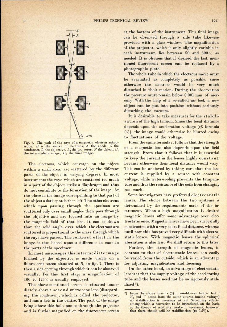
Fig. 7. The path of the rays of a magnetic electron micro-scope. E is the source of electrons, A the anode, C thecondenser, L; the objective, L2 the projector, P the object, Blthe intermediate image, B2 the final image.
The electrons, which converge on the objectwithin a small area, are scattered by the differentparts of the object in varying degrees. In mostinstruments the rays which are scattered too muchin a part of the object strike a diaphragm and thusdo not contribute to the formation of the' image. Atthe place in the image corresponding to that part ofthe ,object a dark spot is then left. The other electronswhich upon passing through the specimen arescattered only over small angles then pass throughthe obj ective and are focused into an ima ge bythe magnetic field of that lens. It can be shownthat the solid angle over which the electrons arescattered is proportional to the mass through whichthe rays have passed. The contrast effect in theimage is thus based upon a difference in mass inthe parts of the specimen.
In most microscopes this intermediate imageformed by the obj ective is made visible on a.fluorescent screen situated at BI in fig. 7. There isthen a side opening through which it can be observedvisually. For this first stage a magnification of100 to 125X is usually employed.The above-mentioned screen is situated imme-
diately above a second microscope lens (disregard-ing the condenser), which is called the projector,and has a hole in the centre: The part of the imagelying above this hole passes through the projectorand is further magnified on the fluorescent screen
at the bottom of the instrument. This final imagecan be observed through a side tube likewiseprovided with a glass window. The magnificationof the projector, which is only slightly variable ineach instrument, lies between 50 and 300X asneeded. It is obvious that if desired the last men-tioned fluorescent screen can be replaced by aphotographic plate.
The whole tube in which the electrons move mustbe evacuated as completely as possible, sinceotherwise the electrons would be very muchdisturbed in their motion. During the observationthe pressure must remain below 0.001 mm of mer-cury. With the help of a so-called air lock a newobject can be put into position without seriouslydisturbing the vacuum.It is desirable to take measures for the stabili-
sa tion of the high tension. Since the focal distancedepends upon the acceleration voltage (cf. formula(4)), the image would otherwise be blurred owingto fluctuations of the voltage.
From the same formula it follows that the strengthof a magnetic lens also depends upon the fieldstrength. From that it follows that it is essentialto keep the current in the lenses highly con sta n t,because otherwise their focal distance would vary.This can be achieved by taking care that the lenscurrent is supplied by a source with constantvoltage, while water-cooling prevents the tempera-ture and thus the resistance of the coils from changingtoo much.Some investigators have preferred electrostatic
lenses. The choice between the two systems isdetermined by the requirements made of the in-strument. When a high magnifi cation is desiredmagnetic lenses offer some advantage over elec-trostatic ones. Magnetic lenses have been succesfullyconstructed with a very short focal distance, whereasuntil now this has proved very difficult with electro-static lenses. With magnetic lenses the sphericalaberration is also less. We shall return to this later.
Further, the strength of magnetic lenses, incontrast to that of electrostatic lenses, can easilybe varied from the outside, which is an advantagefor adjusting magnification and focusing.
On the other hand, an advantage of electrostaticlenses is that the supply voltage of the acceleratingtube and the lenses need not be so rigorously stab-ilized 2).
2) From the above formula (3) it would even follow that ifVo and V come from the same source (mains voltage)no stabilization is necessary at all. Secondary effects,among which a correction to be introduced on the basisof the theory of relativity, make it necessary, however,that there should still be stabilization (to 0.5%).
:-
, , \,...,r j •
-;.", \,
• s , AN ELECTRON MICROS_COPE/
,,;' 39Jt .. ~ . . /'
Th~ instrument decribed in this article i'i equipped' '~._In the casé of the projector of the Inic!,oscopewith magnetic leÎises., '> - :' . ' -. .' ,..~' described here the diameter of the bore 'amounts to
. '," 3.5 mm, so that the di~met~j; of the useful fieÎd, i.e.- , ,The use 0 of an intermediate lens of h 'f ' . I' ,, ~ • , , ' '~ • • . 0, t ë. cross sec~io~ 0 the beam permissih ~ within '. , In the discussion ofthe ~newelectron ~croscope . the lens, is 1 mm. The diameter of the final screen
.we shalrgiv~ special attention to the properties ',:amounts to 18Q mm; If'this 'is 'to be used to :"" ,whjch distinguish it from the electron microscopes its full extent; therefore, a magnification of
-so far described in literature., 180 X -is necessary. The projector has 'thè~efo~e b'een .An impo~tl1:nt, improvement- is the introdué'tion. constructed for this normalmaximum magnification; "
of a third lens between. objective and projector -, with à further increase in' power the ~trength of ~.::. which mak~s it, possible, to vary' the : ~1llJ!gpf, ,the projector ip.creases only slightly. It is of course
. fication continuously between-wide limits: 'possible' to 'obtain an image with a lower magnifi-,~,In order-to' make this clear ,we shall, first, explain \ cation, hut then only part of the _fin~l screen'js, ,
~ ~that in, atwo-stage microscope it Ismrposslble. to, ,filled, so that the' possibilities" of the instrument' ", '- alt'ef the magnification '()ver a wide ràiig~. This is" are not fully ~tilised. . . . <, •• ( • " '
, connected With the 'aberrations .occurring ,undér " ' The magnification by th~ objective 'is entirely'-certaîn:: circumstances and', with the construction - fixed. In this case die position of the object is fixed, '
• f • ' .. - . ._. , , ..'
,of the microscope. ". _' while the image, distance ,is determined by ,the ", . "Ip."el~ctron microscopes aberrations occur' which . position of the object' plane of the projector lying
are analogous t~' those- in optical ·lens~s.. One of -' immediately ab'ov~ that lens. ' J'
.~ . 'the most important ofthese~ the sph~rica~ a,?er- , In á two:st~ge microscope t~e magnificatipn can ' 'r a ti 0 n, resulting from the fact that the edgé'zones of therefore only. be varied within narrow limits., ,
" a lens' are stronger th~n t~e centre. By increasing the " When it is required of a microscope that. th~field. strength '<?f'a lens, it~ focal di~ta~ce, becomes t , magnification sh-,a~~,b'e, ' comp!eteIYi:;controllable, ,.smaller, and with the same/angular aperture a part J special measure's mus~ be taken . .It i's advisable toof the magnetic field lying closer to the axis is used. find a solution where the proj ector, which in any, .The influence of-spherical aberration then becOJ:~es' c~se can' only be changed' to a slight extent, is. ' ....'less. Itis therefore desirable to increase the nU:mber_r ~aintained at 'a/. perfectly. constantstrength.' ...of a~pe:J;e ~urns as much as possible. A limit is set When this is -done it is possible" to adapt this lens ', ' ;:',-to this 'by' the magnetic saturation taking place . entirely to the magnification it is required-to give,
z : in ,the, 'pole' pieces. Nów in order' to, ävoid this, ': i.e. 'to'èÓnstruct it iD. such a waythat with' respect, 'all thê dimensions of the ~le~s could' be ~creased, 'to' distortion it is corrected to a high degree, while'_ :.. put thi~ raises the, difficulties that :the lenses then ' 'the largest possible field' angle is llsed.. ,', " '. consume t~p much energy and' the microscope 'A simple method of varying the magnification',' , , assu~es ,~oo,!a~ge -proporfions. A,~omprorri.ise must' is nçw ,obtained by adding an 'extt'à lens ..between., :therefore he.sought, A satisfactory solution can-be dbjective gnd-' projector. When the 'projector is .
. found, at ~the voltage of 150 kV chosen for Our kept constant the aperture of th~' projector 'm~y be, instrument, by using lenses with about 30QOa-;Upere' considered as the projection screen of the "two-turns. With such lenses a focal distance for the oh- stage microscope" consisting ofthe objective andjective of j = 4.5 mm has been obtained. For, the th:e_new lens. Because the projector has a high 'other, lenses a focal distance of 3.5 mm _can' be magnification .'t}ris -ocular ,aperture will be small, ' -attairied, because in those cases there aié no diffi- even when.a reasonablylargefinalscreeriis provided. ,- ,.culties connected with the in(roduction, of the ,We háve already stated that in our-case the .dia: _'
';"'.specimen. .' , mete; of the bore of the' projector amounts !o 3:5, From calculations of Gla,ser ~nd Do sse it is mm and consequently that of the ocular iaperturefound that only about, 1/4 to 1/3 ,of the -inner .amounts to about 1 mm. ' ,diameter of a magnetic lens may be used if it is. The extra lens - whichwe shall è~ll the In ter-desired to prevent "distortion, an. image aberration." me diat.e le!ls _:_'~eed only fill this- small fieldclosely connected with spherical aberration, from free :of distortion. In the case of the, two-stage
. being l~~ger ~han' J 5 to 10 percent, a limit' 'Which is - 'microscope. discussed above (formed by objective, considered permissible also in the optical microscope. ánd projector) the possibility of regulation, was' onlyAs a result of this limitation the' magnification .of a ', slight because of"the requirement' made that the' \magnetic lens' in a nrièrosc()pe can be .regulated . 'fin~l sereen of 180 min dia~eter should always be ...
v within rather narrow limits, as we shall prove below. filled. Without that requirement variation'ofthe
.:
"
-;
PHILIPS TECHNICAL REVIEW 194740 ', . .,
, magnification wo~ld also have 'b'een po~~ible with lens 'is reduced ~ts magnification decreases. ' Thethat microscope. With" thé- two-stage microscope point, of intersectien of the rays, seen in fig. 8a,formed by objective and intermediate- lens the between the intermediate lens and 'the projector
, requirement is now, made that it shall merely fill then shifts towards ,the projector. When the powera "screen" of 1mm diameter. It will be clear that of the intérmediate 'lens is further reduced there
\ '
this can easily be satisfied also with a great . comes a moment when the above-mentioned pointvariatioIl,' of magnification. . ' ,of intersection of the rays lies in the object plane
The introduetion of an intermediate lens not of the projector. This position is veryImportant,only makes' it possible to vary the magnification, because, as will appear in the continuatien of thisbut 'also the maximum magnification now consider- article, a diffraction image is then obtained. Theably, exceeds that 'which is attainable 'with two magnification is then zero,' As the power is further.lenses. In the case of the microscope described here, ' r~duced the point of intersection falls still lower.
- objective and projector together give a mágnifi-' Upon passing through the' magnification zero the'cation of 6000 times .. By changing the powering image is inverted. The magnification theq increasesof the intermediate lens the - magnification can agáin until finally no pöwer current, at all flows.be varied froin 6000 to 80 000 times. This total', through the' intermediate lens and we have once'magnification is - of course the product of the more the two-stage microscope with whlch we began,magnifiçations of the three separate-lenses. In practice, however, there is 3: serious objection'
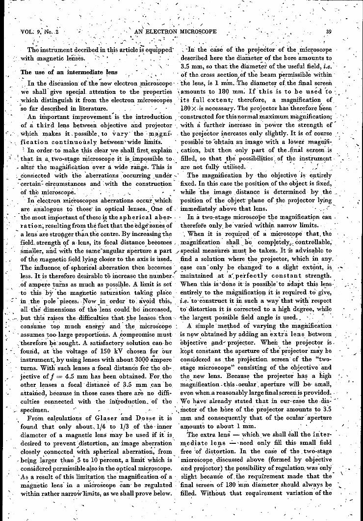
The trajectories when three lenses are us~d are ,to this method. When the point of convergence ofshown diagrammati_cally in fig: Ba. - the rays is shifted to :"a'lower level, an Increasingly,Is it now also possible by means of the- inter- large part of the bore of the mtermediate lens has - .-mediate lens to vary 'the magnification from 6000 to he used, (The final screen must in any case h~-times to' smaller values? Theoretically it certainly filled.) _Theref~re ,the distortion' hIcreases. At lo~is .. ~he.n the R0'Yer supplied to ~he intermediate magnificati,on,' therefore, this image, aberration
c becomes much too large. This could be remediedby making 'the bore of the pole pieces of the inier:mediate lens Iarger,' Then, however, its _minimtiinfocal distance also beéomes larger, so that 'the'maxi-mum magnification of this lens is reduced., A better solution is to use 'another intermediate . "
, lens with .a large bore for the range of l~w magnifi-cations. 'For' these reaSons a fourth lens was',introduced into the microscope. Since this is' alsoused for making dJffr;=tctionpP-?togra:ehs' (this. will' ~be discussed later) it is called the diffraction _
, Ien.s. It is 'situated between the-objective and the', iiÏtermediate lens.' When this fourth len~ is used'the üitermediate Iéns" is 'switched -off;' By varying
.,,; " - th/cUrrent in the diffraction lens the magnificationFig. 8. Diagram of' the path of the rays in the electron can be ~àde vari~ble for all values between 6000microscope described in this article. : and 1000 timès. The magnification of the instru- \Ll ~sthe objective, Lz the projector, Lo the intermediate lens, ' "' 'L4 the dillraction lens, Dl the objective' diaphragm and D2· ment is thu~ as a whole c ont in uo u sly variablethe diffraction diaphragm. fr 1000 80000' Th I limi-, a) The intermediate le~s is in action. Tills lens converges. om to tunes. e ower It gIVes",the rays so strongly that they meet above the projector and, the desired transition to the magnification of the '; ,then form a new intermediate image of the image formed by optical microscope. " r
the objective lens. The intermediate lens makes it possible .'to vary the magnification continuously between 6000X' and In fig. 8b the path. of the rays îs shown, dia- . "80 000x., ' '," - '. II l' h h h diff: ., . b) The difJraction lens deflects the rays which have passed grammatica y ror t e case w ere t e ractionthrough the objective, before they have formed an image, lens is used. This, lens is given such a power that
, and thereby reduces the size cifthe image. The magnifiëatión the point' of convergence of the rays mentioned.'.is variable from 6000X to 1000x.
c) The-microscope is used for studying a diffraction pattern. above Hes' below the object plane of the projeetor.As for image formation, the setting is for the magnification O. The diffraction lens is weaker than the intermediateThe diffraction image, which is formed as "primary' image"in the focal plane of the objective, is projected in magnified lens. It does not give ~a real In te rm ed iat eform ón the finalscreen by the diffraction lens and the projector. ' • I' fr .' I h . •Theobjectivedial!hragmisnowpushed.uptoallowthepassage Image; t re acts more or ess t e,rays.c0D¥ng
, of. the diffraction beams. " , .from thê objective and In,this' way reduces jhe
D,
VOL. 9,No. 2 AN ELECTRON MICROSCOPE 41
magnification as compared with that of the originaltwo-stage microscope.
We shall now first discuss the second functionof the diffraction lens.
The recording of diffraction patterns
In 1927 G. P. Thomson demonstrated m aperfect manner the correspondence between movingele trons and short electromagnetic waves (X-rays),when he showed that it is also possible toobtain the well-known Debije-Scherrer ringswhen beams of fast electrons are sent through thinfoils.The significanee of these d iff'r a ot.i on diagrams
for the identification of substances and the studyof their crystalline state has already been discussedin this periodical 3).
When a sample of a substance is investigatedwith an electron microscope it is in many casesdesirable to have a diffraction pattern of thesubstance at one's disposal at the same time.When a diffraction diagram is to be made with
the electronic microscopes so far described in liter-ature the lenses are switched off. But the smalldiameter of the pole pieces of the projector makesit impossible to record a diffraction pattern imme-diately, because the diffraction rings are then cutoff. Thus either these pole pieces must be removed,which takes some time, or the sample must beplaced in an air lock anew under the projector,or an extra plate camera has to be introduced abovethe projector, which makes the construction muchmore complicated. Only in the last case is it still
48708
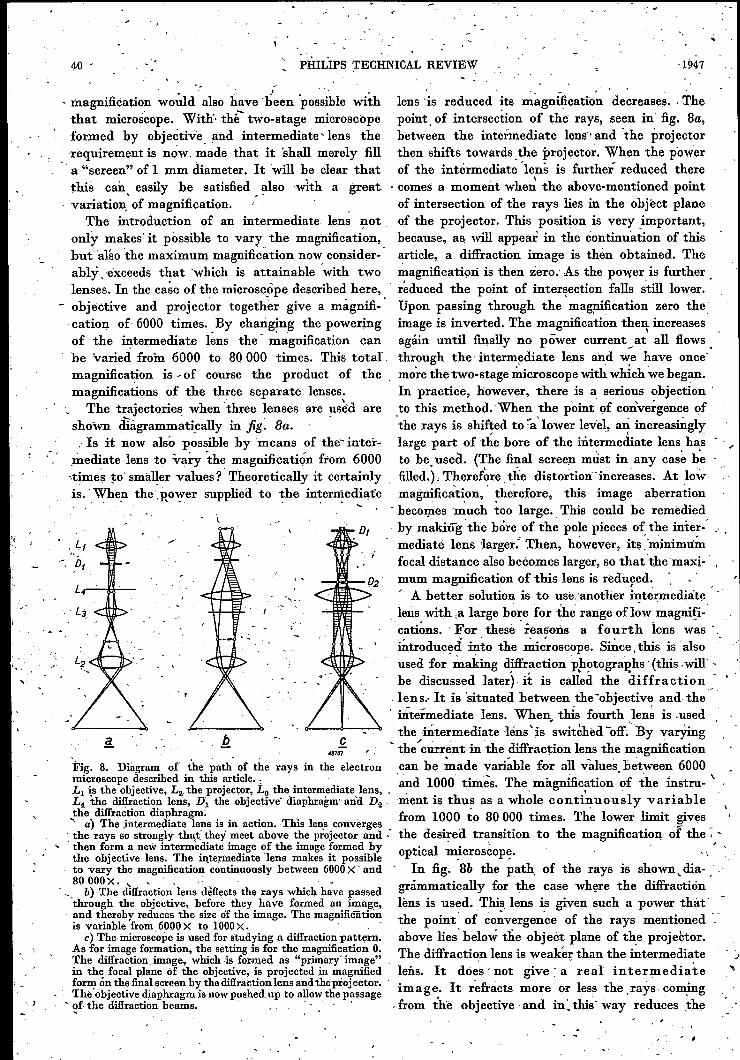
Fig. 9. Diffraction diagram of a gold sol taken with the instru-ment described in this article.
3) W. G. Burgers, X-rays and electron rays as aids inchemical and metallographic investigation. Philips Techn.Rev. 5, 161, 1940.
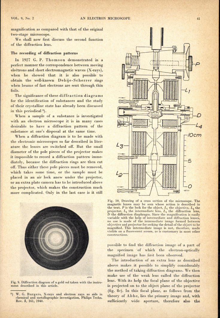
Fig. 10. Drawing of a cross section of the microscope. Themagnetic lenses may be seen whose action is described inthe text. P is the lock for the object, L1 the objective, L2 theprojector, L3 the intermediate lens, L4 the diffraction lens,D the diffraction diaphragm. Since the magnification is easilyvariable with the help of intermediate and diffraction lenses,no use is made of the intermediate image formed betweenobj ective and proj ector for seeking the detail of the obj ect to bemagnified. This intermediate image is not, therefore, madevisible on a fluorescent screen, as is customary in most otherconstructions.
possible to find the diffraction image of a part ofthe specimen /of .which the electron-opticallymagnified image has first been observed.
The introduction of an extra lens as describedabove makes it possible to simplify considerablythe method of taking diffraction diagrams. We thenmake use of the weak lens called the diffractionlens. With its help the focal plane of the objectiveis projected on to the object plane of the projector(fig. 8c). In this focal plane, as follows from thetheory of Abbe, lies the primary image and, withsufficiently wide aperture, therefore also the
can be accurately adjusted from the outside.But when diffraction is employed it is just thestrongly scattered rays which are needed. For thatpurpose the objective diaphragm is raised and thusput out of .action, the diaphragm in the diffractionlens then being brought into play. In this lens thereare two diffraction apertures of different size, whichcan be used at discretion. When the small apertureis used it is possible to make diffraction diaphragmsof very small regions, for when the object is sharplyfocussed on this diaphragm only those electronscan pass through which come from the correspond-
ing part of the object. In thecase of the microscope describedhere the magnification on thediaphragm is 13 x. When theaperture of 40 (1. is used it ispossible to scan the object andto cut out regions with a diameterof 3 fL.The great advantage ofthis
construction is that it is easy toswitch over from the electronimage to the diffraction imageand that one can then observea difiraction pattern of that partof the object whose image hasfirst been studied microscopically.This furnishes a good methodfor the identification of thecrystals in the specimen beinginvestigated.
42 PHILlPS TECHNI CAL REVIEW
diffraction image (cf. fig. 1). This diffraction imageis very small owing to the small focal distance ofthe ohjective, but the projector enlarges it to thesize customary for such patterns. Fig. 9 gives anexample of a diffraction pattern obtained in thisway.In order to obtain good image formation with
sufficient contrast when using the instrument in anormal way, it is necessary to screen off the raysthat are too strongly scattered by the specimen.For that purpose a diaphragm with an apertureof about 70 (J. is introduced in the objective, which
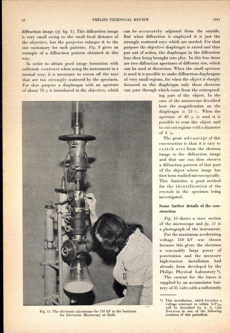
Fig. 11. The electronic microscope for 150 kV in the Institutefor Electronic Microscopy at Delft.
1947
Some further details of the con-struction
Fig. 10 shows a cross sectionof the microscope and fig. 11 isa photograph of the instrument.
For the maximum acceleratingvoltage 150 kV was chosenbecause this gives the electronsa reasonably large power ofpenetration and the necessaryhigh-tension installation hadalready been developed by thePhilips Physical Laberatory 4).
The current for the lenses issupplied by an accumulator bat-tery of 35 volts with a sufficiently
4) This installation, which furnishes avoltage constant to within 0.2%°'will be described by A. C. vanDorsten in one of the followingnumber~ of this periodical.
VOL. 9, No. 2 AN ELECTRON MICROSCOPE 43
constant voltage. The maximum current per lensis about 1.4 ampere. Each of the lenses is cooledseparately. In order to obtain a rapid dissipationof heat, layers of copper are introduced betweenthe windings at regular intervals. The conductionof heat towards the cooled side walls is thus in-creased, so that a current density of 6.5 A/mm2
became permissible.The introduçtion of a third lens between objective
and projector also gives the advantage that thelength ofthe microscope tube could be considerably. decreased. The total distance from the objectto the final image in the new microscope amountsto 600 mm, which is short considering that thediameter of the final image is 180 mm.The electrons thus have short trajectories, and
that also has several advantages. In the first placethere is less chance of collision with residual gasmolecules in the tube, and in the second place theinfluence of disturbing fields is less. The path ofthe rays between the objective and the next lensis most sensitive to these fields. Its length in ourmicroscope amounts to only 10 cm, compared with30 cm in the model' which until now was the bestin that respect. Moreover, owing to the compactstructure the path of the rays is doubly shieldedby the tube itself and by the coil jacket. As a thirdadvantage of a short microscope tube the smallvolume may be mentioned, which makes it possibleto reach a high vacuum more quickly.
The coils of the rarious lenses are separated bythe iron side walls of the jackets. Only betweenthe objective and the diffraction lens is a small~pace left free in which several essential componentsare housed: in the first place the three adjustingscrews by means of which the objective can bealigned with respect to the other lenses; further asimilar arrangement for adjusting the objectivediaphragm - here is also located the fork with whichthe last mentioned diaphragm can be moved upfor making diffraction photographs - and finallyin this space the diaphragm holder is housed withthe two already ~entioned apertures of differentsize for the electron diffraction. The larger or thesmaller of these can be used at will, or the passagecan be made entirely free. All these arrangementscan be operated while the microscope is in use.In electron microscopy the visual image is
usually only used to obtain an impression of thespecimen and for sharp focusing. The most impor-tant observations, however, are made photo-graphically. A photographic plate or film mustthen be brought into the path of the rays.
It is desirable to obtain sharp photographs of
the who Ie image. As already stated, the diameterof the final i:r;nageis 180 mm. It would bë difficultto introduce a photographic plate of that size intothe vacuum close to the final screen. We thereforeuse a 35 mm film, which, in order to be able tocover the whole image, is introduced at a spot wherethe cross section of the beam is still sufficientlysmall. Because of the small apertures customaryin electron microscopy, the depth of focus is morethan sufficient to obtain a sharp image at that spotwithout a new adjustment. In this way the ex-posures are made with IJS ofthe total magnification.This must not, however, by any means be ,con-
sidered as a disadvantage. The resolving power ofthe film is much better than that of the' eye. It istherefore possible subsequently to enlarge the smallphotographs more than five times.The fact that the camera is 'placed close to the
projector has also. the advantage that because ofthe high current density of the beam impingingon the film a short exposure is sufficient.It is obvious that in visual ohservations the
camera must be removed from the beam of the rays.Itwas found, possible to introduce a simple arrange-ment with which the film holder can be -tipped
-I87/Q
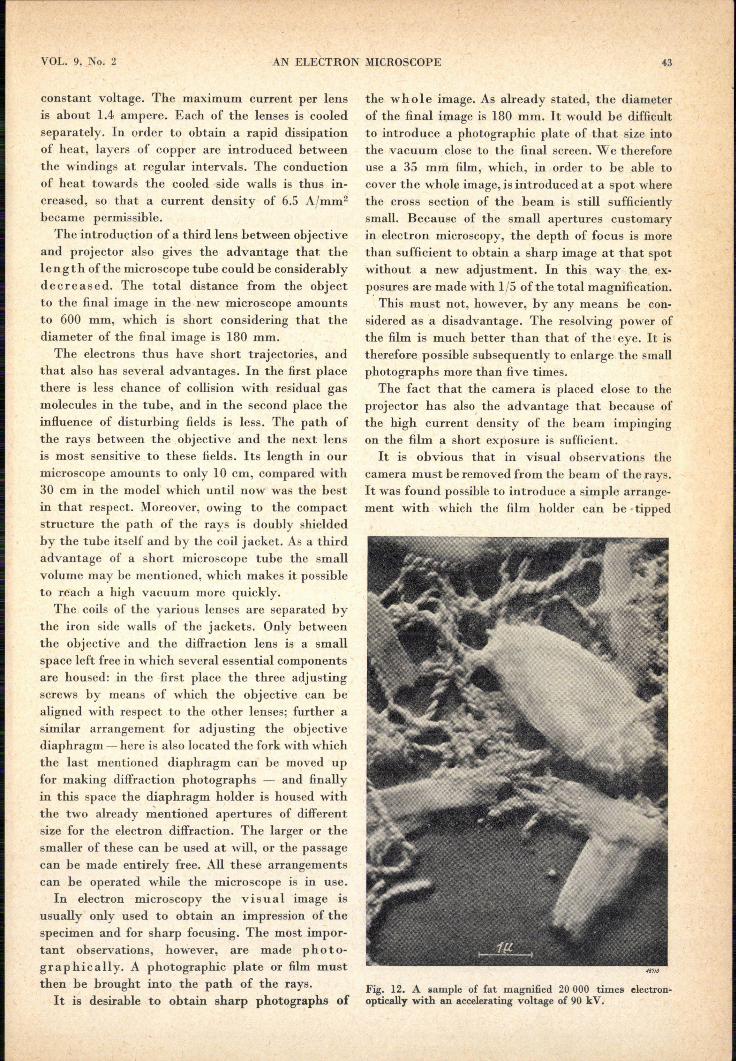
Fig. 12. A sample of fat magnified 20 000 times electron-optically with an accelerating voltage of 90 kV.
44 PHILlPS TECHNICAL REVIEW 1947
upwards from the outside. In order to preventdouble èxposure the film is automatically shiftedwhen the camera is tipped up. When 25 photographshave been made a new film must be placed in thevacuum. Then the whole microscope has to be ex-hausted anew. Although in this process the gaseswhich the new film brings with it have also to beremoved, this operation does not take longer thanabout 10 min.
One of the difficul'ties attending the use of highmagnifications is the low brightness of the finalimage. This makes the focusing very difficult.A special focusing arrangement has thereforebeen introduced.
By means of the electric field between two setsof parallel plates situated between the condenserand the objective lens, the incident ray is causedto oscillate back and forth with a frequency of50 c/sec. When the microscope is not exactlyfocused this oscillation will blur the image. Thepower current of the objective is now varied until,in spite of the oscillation of the incident ray,the image remains sharp, whereupon the voltageon thf deflection plates is switched off again.
The-focusing arrangement is so constructed thatthe incident beam oscillates over an angle ofljl00 radian. Very good results are obtained withthis method. Since in this way rays which have anaperture 20 times as large as the beam used forimage formation are focused as well as possible,the adjustment can be improved by a factor of 20.
In conclusion it may be mentioned that theresolving power of the microscope lies between25 and 30 Ángström. It will be possible to approachthe theoretical limit of 5 Á, mentioned at thebeginning of this article, more closely by improvingthe rotational symmetry of the lenses.
Infi,'is.12 and 13 two photographs are reproducedwhich were taken with this instrument.
Summarizing, the most important advantages ofthe electron microscope described here as comparedwith previous types are the following:1) The magnification can easily be continuously
varied between 1000 X and 80 000X .• 2) The length is shorter and therefore the effect
of disturbing fields is also smaller.3) The image field is much larger.4) With the 35 mm camera it is possible to make
a large number of exposures in a short time.5) A special arrangement provides 'for accurate
focusing.6) It is possible to pass over immediately from
electron to diffraction pattern and to make a
diffraction pattern exposure of a selected regionof 3 [.I. diameter in the sample whose image' hasfirst been studied microscopically.
Applications of the electron microscope
The electron microscope has opened up entirelynew fields of investigation for various branches ofscience. Its applications are widely varied and wecan only mention a few of them.
44711
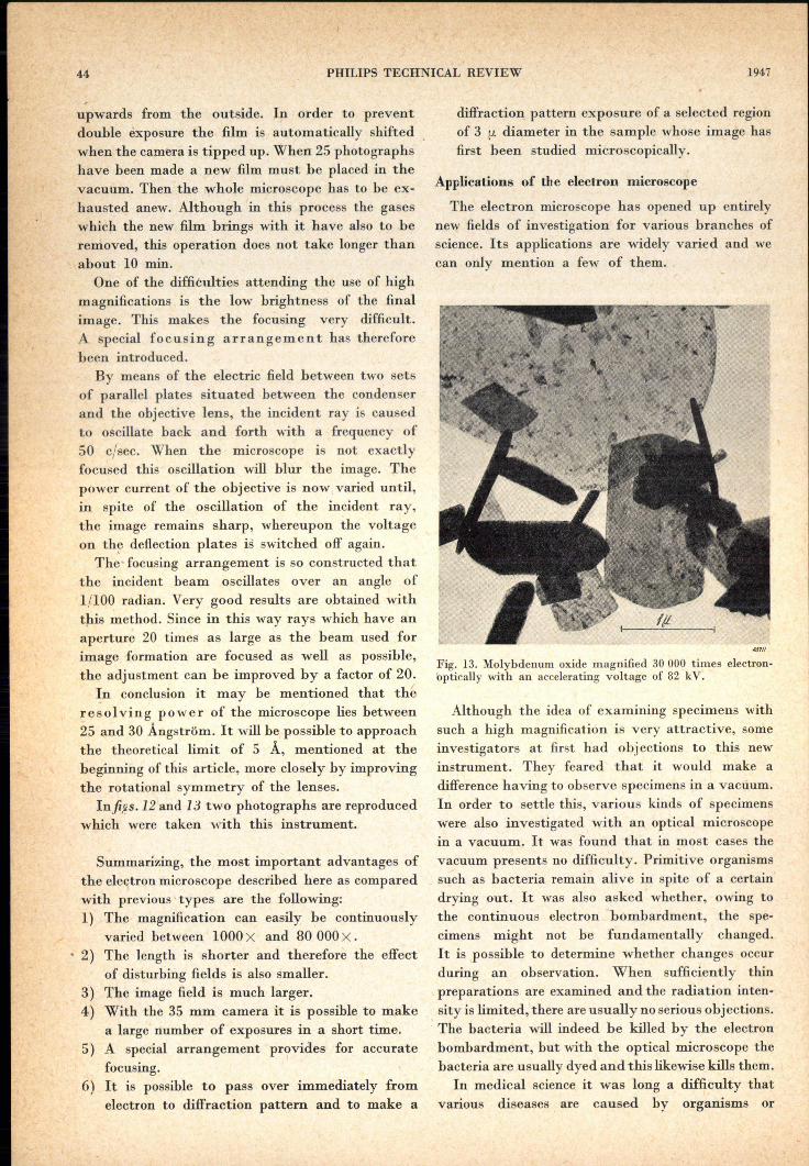
Fig. 13. Molybdenum oxide magnified 30 000 times electron-optically with an accelerating voltage of 82 kV.
Although the idea of examining specimens withsuch a high magnification is very attractive, someinvestigators at first had objections to this newinstrument. They feared that it would make adifference having to observe specimens in a vacuum.In order to settle this, various kinds of specimenswere also investigated with an optical microscopein a vacuum. It was found that in most cases thevacuum presents no difficulty. Primitive organismssuch as bacteria remain alive in spite of a certaindrying out. It was also asked whether, owing tothe continuous electron bombardment, the spe-cimens might not be fundamentally changed.It is possible to determine whether changes occurduring an ohservation. When sufficiently thinpreparations are examined and the radiation inten-sity is limited, there are usually no serious obj ections.The bacteria will indeed be killed by the electronbombardment, but with the optical microscope thebacteria are usually dyed and this likewise kills them.
In medical science it was long a difficulty thatvarious diseases are caused by organisms or
.' '-, . <
1.
I
,_,(- ' \ '.
'Î
'" .. '
AN ELECT]W~ MICROSCOPE'.' .:::., """ ...
.'.' 45
I
,VOL.. 9, No. 2
, \
: \.
substan:ée~which are invisible ~der an ordina:ry ,'only in~de clearly' "visible ' :With: el~ctron .riys. '"microscope. Such 'ia.' virtis elm' as '~ rule be·, : For miner'alogy' and technolo-gy the,'n~wmi-observed with a~ electron lni6róscope.:'- »Ó» ' è~os~opeis also an iillpofiani aid.' In the problems'
,~, , With this instrument it is alsopossible to observ~ there -ell'counteredit is 'often desired'also to be' able'. / stru'ctu~ál elements only' a fewmu' i;; size ill tuJier! to obsen::ea diff~acti~ndiagram ill' order to 'identify
• ~ ", 1 .• ' " . . ~. ..;1-.... I
. "culus bacillae and other .bacteria.v which 'provides. the crystals with the J.telpofthe Dèb ij e-Sch er r er, . ,I • '. •
,_ .the possibility of distinguishing ,morphologically . rings. It is of gr~at advantage whe;'lOlieca~ easilydifferent types .of / disease 'producers:' Further, . switch over from the electron' to the diffraction
I 'me~dical investigators and biologists* have' made image'. ,',/' " " ,.'') use ,of the instrument to study the' structure 'of In the field ofsilicates, hy the application' of themuscles.and 'nerve fibrilla:as ~ell "asthe structure ',' new method discov~ries ha~e been made which.'
, of, protoplasm 'and the .proble~s: of chr~m.~somê' are of great importance in ceramics, '; , " ., structure and 'the, àrràngement,'óf. the genes. 'It It is import'ant to note that here there hasbeen
, " 'Was ~lso' ve~y important' that' várious 'not ' yet a 'ttansition~ from qualitative to, "quantitatiye, .", - ,_ , . .' . - .' ~ . . . \ "'"
-:. 'completely 'explained processes, such ,a~thè 'occur- "methods. The adsorption power' of the Surface of ': ._rence of coagulation in: blood, ~ould' be studied particles of clay has Mte"D.to be investigat~d", .'.,
_ ',-under' very; high,magnificationk.' '. ': :,'; One then ~~unts aiId measures under an electron' J' -< -, ", 'Ma,ny' plant diseases,are also calÏs~d by viruses., microscope,for instance, 1000~c~yst~lsofa substance' -,
,-' ,.The .virus 'of-the tobacco mosaic disease and :that . and 'n{akes a', distribution -curve..of their' sizes: . "," of a' -Verydestructive 'potato'..dise.ise'h'ave, among' In making such distrihution curves it is vêfy desir~
. ;",~others, beex:..made ,visible::wi~h the -. electron.. ,able to he able to change 'over ,Casily to à. l~w!'l~.. . . microscope. This has, led to' great advances being" magnification.The s~udyof chemical processes at i\
made Îl:!'phyto.Plitholögy .in ,r~.ce~t·years. '1,'he. magnification ,of '20,~OO to 30000 x' ,is also~very" ~"viruses often prove to be rodlike in shape and of " instructivevAs an r example-wetmay mentioü-an"die orde~of magnitude of molecules. v , " excellent investigatiOli' of '.~he 'manner 'in ~hiéh.,It'has, al~~ been; possible 'withJ, an electron an image is,formed"on a 'photographic plate, which
'$icp?~cope to ~ake various bacteriophages visible.' was carried out by V 0 n: Ar d enn é,before '1940.",These'are kinds' of. viruees'which destroy certain " It'may.be·àssumed that'within a reasonable tini~' ,
,~ )acteri~. This process .:..-,called bacteriophage every., laig_e hospital and v every ,~aboratory f?r":. ." lysi~~_:_has 'also heen investigated With the elec- researc~ i~ the' field of·microbiology, mill,eralogy.·, "tron jnicroscope'.' ,-, and tecluiology.,will be employing e~ectr~nmicr?- . ~l''. Bacteria .had already long .bèén observed with scopes. ,... .' " "'. ~\.
':, the. 'optical microscope, but -rhe, 'cilia of these '. -At the Institut» for Electron Microscópy' at,~ ,o~ganisms, w~ch have à 'thick~es's','~f from 0.02,. Delft the microsc~pe d~sér~ed, here,has IC?p.~bee,n", ': .<\", to.' 0.02 (I., 'and all kinds of details: and COIn:" in' 'daily use' for investigations in the interest 'df .. ',~ - - •• .... .-_- ,"," . -' ~ ~- / # "
~', .l'~cated structures of the ~\a~teiial cell ~erë , industry and scie~~e. ,-,' , ',' ,:.- _v .\. .' ;
"
,,~ ...
,'. ."
, -,-t..'_ I F~': .
\ ," . ",',"'. ;
", '"
., '\i •
J', '
, .. -,"
. ,I,
" .. ~t •
, .'\ / ,
'. \, , ,
, . " / ., '. , ,
' ... '.. ',-
': . , ': .,ol •
,_, ,"
""
-, J'