Embed Size (px)
Citation preview
be
arting era.
ents ly of
you
a.
your lt IP 0).
Step 6 — Evaluate a Captured Image and Auto CalibrateYou will see the Image view after selecting your device. This view allows you to evaluate your first image capture, providing information such as image size and a histogram. Click the Auto Calibration button to set optimal camera parameters automatically. You can also adjust Exposure, Gain, and Focus as needed, and set the desired Lighting Mode.
Step 7 — Create Your First Job with AutoVISIONAfter you have evaluated a captured image and Auto Calibrated the camera in the Image view, you will move to the Edit view. This interface allows you to set camera parameters, add machine vision tools to captured images, set tool parameters, and configure I/O inspection outputs.
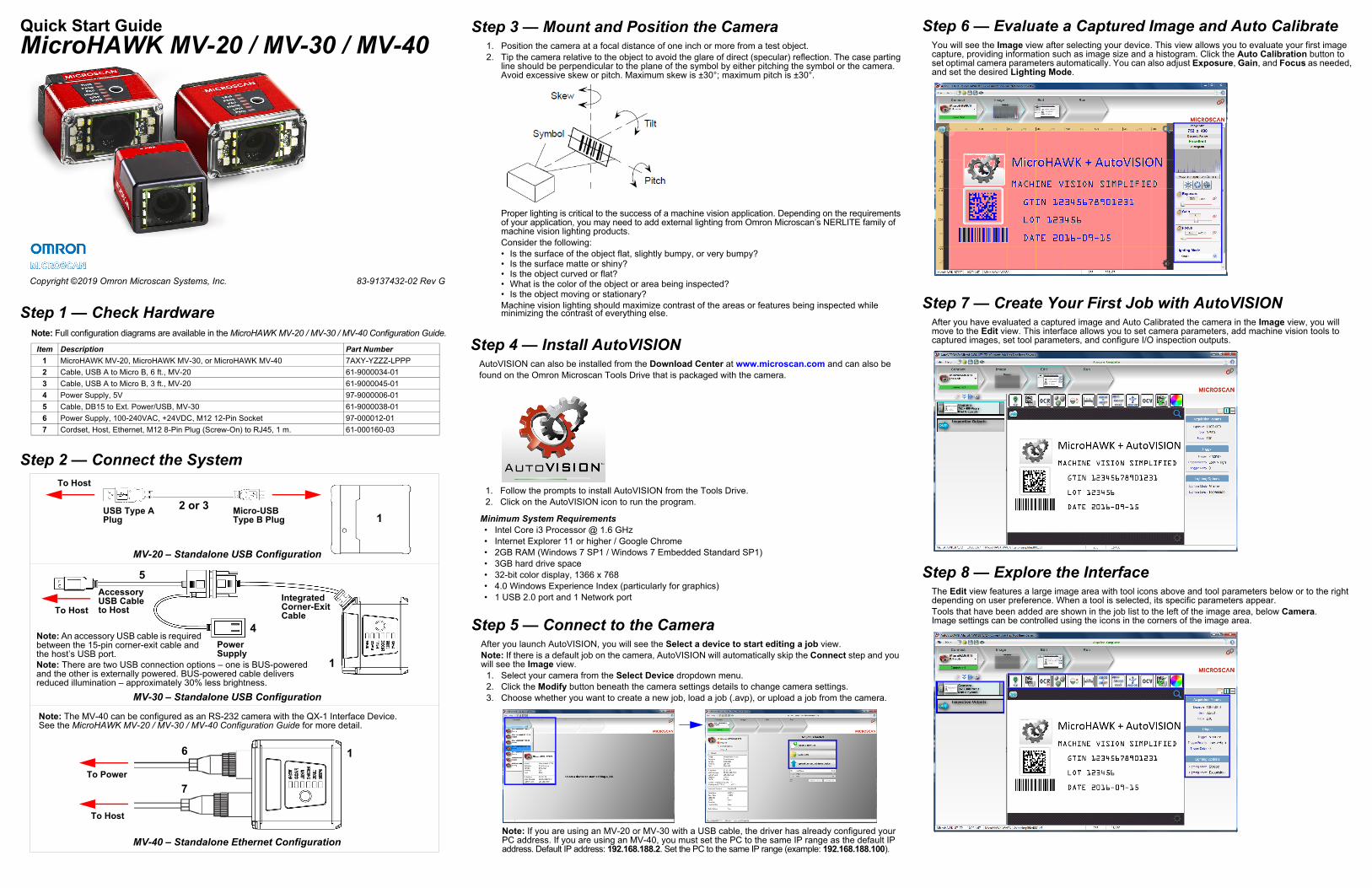
Step 8 — Explore the InterfaceThe Edit view features a large image area with tool icons above and tool parameters below or to the right depending on user preference. When a tool is selected, its specific parameters appear.Tools that have been added are shown in the job list to the left of the image area, below Camera. Image settings can be controlled using the icons in the corners of the image area.
Step 4 — Install AutoVISIONAutoVISION can also be installed from the Download Center at www.microscan.com and can alsofound on the Omron Microscan Tools Drive that is packaged with the camera.
1. Follow the prompts to install AutoVISION from the Tools Drive.2. Click on the AutoVISION icon to run the program.
Minimum System Requirements• Intel Core i3 Processor @ 1.6 GHz• Internet Explorer 11 or higher / Google Chrome• 2GB RAM (Windows 7 SP1 / Windows 7 Embedded Standard SP1)• 3GB hard drive space• 32-bit color display, 1366 x 768• 4.0 Windows Experience Index (particularly for graphics)• 1 USB 2.0 port and 1 Network port
Step 3 — Mount and Position the Camera1. Position the camera at a focal distance of one inch or more from a test object.2. Tip the camera relative to the object to avoid the glare of direct (specular) reflection. The case p
line should be perpendicular to the plane of the symbol by either pitching the symbol or the camAvoid excessive skew or pitch. Maximum skew is ±30°; maximum pitch is ±30°.
Proper lighting is critical to the success of a machine vision application. Depending on the requiremof your application, you may need to add external lighting from Omron Microscan’s NERLITE famimachine vision lighting products.Consider the following:• Is the surface of the object flat, slightly bumpy, or very bumpy?• Is the surface matte or shiny?• Is the object curved or flat?• What is the color of the object or area being inspected?• Is the object moving or stationary?Machine vision lighting should maximize contrast of the areas or features being inspected whileminimizing the contrast of everything else.
Step 5 — Connect to the CameraAfter you launch AutoVISION, you will see the Select a device to start editing a job view.Note: If there is a default job on the camera, AutoVISION will automatically skip the Connect step andwill see the Image view.
1. Select your camera from the Select Device dropdown menu.2. Click the Modify button beneath the camera settings details to change camera settings.3. Choose whether you want to create a new job, load a job (.avp), or upload a job from the camer
Note: If you are using an MV-20 or MV-30 with a USB cable, the driver has already configured PC address. If you are using an MV-40, you must set the PC to the same IP range as the defauaddress. Default IP address: 192.168.188.2. Set the PC to the same IP range (example: 192.168.188.10
Quick Start GuideMicroHAWK MV-20 / MV-30 / MV-40
Copyright ©2019 Omron Microscan Systems, Inc. 83-9137432-02 Rev G
Step 1 — Check HardwareNote: Full configuration diagrams are available in the MicroHAWK MV-20 / MV-30 / MV-40 Configuration Guide.
Item Description Part Number1 MicroHAWK MV-20, MicroHAWK MV-30, or MicroHAWK MV-40 7AXY-YZZZ-LPPP2 Cable, USB A to Micro B, 6 ft., MV-20 61-9000034-013 Cable, USB A to Micro B, 3 ft., MV-20 61-9000045-014 Power Supply, 5V 97-9000006-015 Cable, DB15 to Ext. Power/USB, MV-30 61-9000038-016 Power Supply, 100-240VAC, +24VDC, M12 12-Pin Socket 97-000012-017 Cordset, Host, Ethernet, M12 8-Pin Plug (Screw-On) to RJ45, 1 m. 61-000160-03
Step 2 — Connect the System
MV-20 – Standalone USB Configuration
To Host
USB Type A Plug
Micro-USB Type B Plug 1
2 or 3
MV-30 – Standalone USB Configuration
1
1
MV-40 – Standalone Ethernet Configuration
To Power
Note: An accessory USB cable is required between the 15-pin corner-exit cable and the host’s USB port.
To Host
To Host
Power Supply
Integrated Corner-Exit Cable
Accessory USB Cable to Host
Note: The MV-40 can be configured as an RS-232 camera with the QX-1 Interface Device. See the MicroHAWK MV-20 / MV-30 / MV-40 Configuration Guide for more detail.
5
4
6
7
Note: There are two USB connection options – one is BUS-powered and the other is externally powered. BUS-powered cable delivers reduced illumination – approximately 30% less brightness.
d the tools y
the age,
Power Requirements and Pin AssignmentsMicroHAWK MV-20: 5VDC ± 5%; 350 mA at 5VDC (typ.) MicroHAWK MV-30: 5VDC ± 5%; 600 mA at 5VDC (typ.) MicroHAWK MV-40: 4.75 – 30VDC; 200 mV p-p max ripple, 150 mA at 24VDC (typ.)Important: See the MicroHAWK MV-20 / MV-30 / MV-40 Smart Camera Guide for full electrical specifications.MicroHAWK MV-20 Micro-USB Type B Socket
Pin Function1 Vbus (5V)2 D–3 D+4 N/C5 Ground
MicroHAWK MV-30 High-Density 15-Pin Dsub USB/Serial Socket
MicroHAWK MV-40 M12 Connectors
Pin Function1 +5VDC2 TX2323 RX2324 GND5 D+6 N/C7 Output 1+8 Default+9 Trigger+
10 D–11 Output 3+12 New Master+13 N/C14 Output 2+15 Vbus
Ground
Output 3
Output 1
Output 2
New Master Default
Power
Input CommonOutput Common
RS-232 (Host) RxD
Trigger
RS-232 (Host) TxD
M12 12-pin Plug
Note: An accessory cable is required between the MV-30’s 15-pin corner-exitcable and the host’sUSB port.
TX (+)
RX (–)
RX (+)
TX (–)
V+
V–
M12 8-Pin Socket (Ethernet)
V+
V–
MicroHAWK MV Part Number StructureMicroHAWK MV part numbers follow the format 7ABX-YZZZ-LPPP.7 = MicroHAWK. Example Part Number: 7412-2000-2104Description: MicroHAWK MV-40, IP65 Case, 24V, Ethernet, Machine Vision, SXGA, 1.2 Megapixel, Mono, High-Density, Autofocus, White Outer LEDs, AutoVISION + Verification + Visionscape.(A) Model1: Engine, No Case, USB2: MV-20, IP40 Case, USB3: MV-30, IP54 Case, 5V, USB4: MV-40, IP65 Case, 24V, Ethernet(B) Application Type 1: Machine Vision(X) Sensor 1: WVGA, 0.3 Megapixel, Mono 2: SXGA, 1.2 Megapixel, Mono 3: QSXGA, 5 Megapixel, Color(Y) Optics0: Custom1: Standard-Density2: High-Density3: Ultra-High-Density4: Long-Range (Autofocus Long Range available for SXGA sensor only.)5: Ultra-High-Density with Polarizer(ZZZ) Focus Distance 000: Autofocus050: 50 mm = 1.96 in.064: 64 mm = 2.51 in. – UHD FF081: 81 mm = 3.18 in.102: 102 mm = 4.02 in.133: 133 mm = 5.23 in.190: 190 mm = 7.48 in.300: 300 mm = 11.81 in.400: 400 mm = 15.75 in. – UHD FF(L) Outer LED Color 0: N/A (Engine and MV-20)1: Red (Not available with QSXGA sensor.)2: White3: Blue4: IR(PPP) Software License Bundles 100: AutoVISION Sensor101: AutoVISION102: AutoVISION + Visionscape103: AutoVISION + Verification104: AutoVISION + Verification + VisionscapeNotes:• (A) Model: The MicroHAWK Engine is available for OEM-certified partners only.• (L) Outer LED Color: Outer LEDs provide extra illumination. Base level illumination included with all cameras.• Field Upgrades: Not available for optics or illumination due to factory settings for optical alignment, LED balancing, and
sealing for IP enclosure rating. However, the camera’s software is field-upgradeable via licenses.
WVGA 752 x 480, 0.3 MP, Mono Global Standard: 10 FPS / High: 52 FPSSXGA 1280 x 960, 1.2 MP, Mono Global Standard: 10 FPS / High: 40 FPS
QSXGA 2592 x 1944, 5 MP, Color Rolling 5 FPS
Step 12 — Run the JobWhen all job parameters are set, click on the Run step at the top of the interface. The software will downloavision job just created to the camera and will begin the inspection. Inspection results and the list of activeare shown at the right of the image view. That information can also be moved below the image area bclicking the orientation buttons above the inspection results area.
Test JobsNote: For descriptions of more advanced functionality, such as setting Inspection Outputs or using Locate Tool and Decode Tool’s Dynamic Locate functionality to track multiple tools from image to imsee the help documentation in AutoVISION software.
Decode Tool, OCR Tool, Match Strings Tool, String Format Tool
Measure Tool, Count Tool
LOT 123456DATE 05/2024
VISIONSIMPLIFIED
Measure:Measure the distance betweenthe jaws of the caliper gauges at left.
Count:Count the circles on the dice shownat right.
Step 9 — Set Camera Parameters1. Click on the Camera box to the left of the image area.2. In the camera parameters below the image area, select the desired type of Trigger, Trigger Polarity,
Photometry (Exposure and Gain), Focus, and Lighting.
Step 10 — Add Tools to the Job1. Click on the Decode Tool or drag it onto the image area.2. Use the anchor points at the corners of the region of interest to form a box around the Data Matrix
symbol. Leave plenty of space on each side of the symbol.3. Now add a second Decode Tool and do the same for the 1D symbol below the Data Matrix symbol.4. Finally, add an OCR Tool and drag the region of interest around the area of the image where “123456”
is printed.
Step 11 — Try Out the JobOnce you have configured the tools as desired, use the arrow icons in the Job area to try the job you have just created.Note: Most jobs will inspect multiple captured images. If only one image is being inspected, the effect of the arrow icons will not be evident.
Try Out Job Once
Try Out Job in Loop
Copyright ©2019 Omron Microscan Systems, Inc.