Embed Size (px)
Citation preview
ISSN(Online) : 2319-8753 ISSN (Print) : 2347-6710
International Journal of Innovative Research in Science, Engineering and Technology
(An ISO 3297: 2007 Certified Organization)
Vol. 5, Issue 4, April 2016
Copyright to IJIRSET DOI:10.15680/IJIRSET.2016.0504236 6353
Experimental Investigation on Multi Pass Drilling of GFRP Using Fuzzy Inference System
S.Sankara Narayanan1, Dr.B.Kumaragurubaran2, Dr.T.Senthil Kumar3, N.Ganesh4
P.G Scholar (M.E - Manufacturing Engineering), Department of Mechanical Engineering, University College of
Engineering, BIT Campus, Anna University, Trichy, Tamil Nadu, India,1
Assistant Professor, Department of Mechanical Engineering, University College of Engineering, BIT Campus, Anna
University, Trichy, Tamil Nadu, India,.2
Professor, Department of Mechanical Engineering, University College of Engineering, BIT Campus, Anna University
Trichy, Tamil Nadu, India.3
Assistant Professor, Department of Mechanical Engineering, K.Ramakrishnan College of Engineering, Trichy, Tamil
Nadu, India4
ABSTRACT: Drilling is a hole making process in metal cutting operation performed by extrusion which finds wide application in various industries for manufacturing components using metals and non metals. This process is applied widely in assembly of components or elements, where processing challenges are severe issue such as to maintain surface integrity, ovality, machining time, Metal Removal Rate etc., In the recent trends of engineering GFRP is a fast growing material which found to have the application of drilling operation and also facing the above mentioned processing challenges in the hole making process. So in this work the drilling of GFRP was investigated for characteristic behavior of cutting parameters spindle speed, feed with 10 mm diameter of hole. The experiment was carried out using 6 mm HSS, 6 mm TiN coated HSS,10 mm HSS, 10 mm TiN coated HSS drill bits in three different configuration of drill pass ie., three multipass (1. 6mm HSS then 10mm HSS drill 2. 6mm TiN coated HSS then 10mm TiN coated HSS drill 3. 6mm TiN coated HSS then 10mm HSS drill). The responses considered were Surface finish, Delamination, ovality and machining time were tested for significance for the effects of parameters and the results were found to be good. The inferences were analyzed both in regression modeling and fuzzy logic modeling and it was found that the fuzzy logic gives more detailed inference system comparatively than regression modeling. KEYWORDS: single objective, GFRP, delmaination, drill combination, speed, feed, Taguchi method, FIS.
1. INTRODUCTION GFRP is an emerging composite material widely used in almost all the vital components of the present and the mere future to come. GFRP is replacing conventional metallic materials which are being used in manufacturing of engineering application components. They are used in aerospace, ships, automobiles and sports. Composite materials have many positive properties such as light weight, high strength, high stiffness, corrosion and fatigue resistance. Composites are materials comprising of more than one constituent material resulting in superior quality than the conventional material. GFRP is an anisotropic and inhomogenous material which results in delamination, burrs, swelling ,ovality and fibre pullout and poor surface finish.
II. LITERATURE REVIEW Eda Okutan et al. [1] conducted the study on the derivation of parametric cutting force equations in drilling of GFRP Composites using DIN 338 HSS drills. Machining of the GFRP samples was performed with different diameters of
ISSN(Online) : 2319-8753 ISSN (Print) : 2347-6710
International Journal of Innovative Research in Science, Engineering and Technology
(An ISO 3297: 2007 Certified Organization)
Vol. 5, Issue 4, April 2016
Copyright to IJIRSET DOI:10.15680/IJIRSET.2016.0504236 6354
drills and different feed rates. To minimize vibration during machining, the drill dynamometer was fixed to the table of the machine It was determined that when the drill diameter and feed rate are increased while machining GFRP, the thrust force and drill torque increase. B.Ramesh et al. [2] studied Experimental investigation and optimization in Drilling GFRP polymeric composites using Taguchi and ANOVA to determine the surface roughness and delamination factor. The drill tool used was coated cemented carbide drill. The experimental result shown that The optimal process parameter levels for drilling non-laminated GFRP composites to produce lower order damage factor at entrance are 0.15 mm/rev feed and 1250 rpm speed and that to produce lower order damage factor at exit are 0.05 mm/rev feed and 1000 rpm speed. K. Giasin et al. [3] has conducted drilling test on GLARE fiber metal laminates using TiAlN coated carbide twist drills and observed that increase in feed rate increases the cutting force, increase in spindle speed reduces the cutting forces. Fiber orientation in GLARE had no influence on the cutting forces. Shiba narayan sahu et al. [4] conducted drilling experiment on GFRP using 8 facets solid carbide drill bit. The work focused effects of cutting parameters on Thrust force and torque. The inferences shows feed is proportional to thrust force and torque. Speed is inversely proportionally to the thrust force. The cutting parameters has been optimized using CNSGA – II algorithm. Hari Vasudevan et al. [5] conducted experimentally investigated on multi objective optimization of drilling characteristics for NEMA G-11 GFRP/ EPOXY composite. In this work the desirability optimization is used to find optimal cutting parameters. The experiment is designed using Taguchi’s design. The experiment is carried out using WC drill bit. It was concluded that Delamination increases with drill diameter. If feed rate is increased hrust force is increased. Vikas Sonkar et al. [6] investigated on drilling of GFRP composites using TiAlN coated solid carbide drill bits. The process parameters considered in this work are Spindle speed, Feed rate, Plate thickness, Drill diameter. Optimal parametric combination obtained from TOPSIS and Deng’s similarity method have been found similar to each other.Sunil Hansda et al. [7] experimentally analyzed the effects of Material thickness, drill diameter, spindle speed, feed rate in drilling of GFRP using HSS twist drill for responses Delamination and surface roughness. The prediction shows Spindle speed is insignificant and feed is highly significant and effective than drill diameter and material thickness. Pandu R. Vundavilli et al. [8] carried out drilling investigation on GFRP using Polycrystalline Diamond, with application of Differential evolution and particle swarm optimization, Artificial bee colony algorithms and found optimal values of cutting parameters. Vinod kumar vankanti et al. [9] considered chisel edge width and point angle also as process parameters in addition to speed, feed and the objectives selected were Torque, thrust force, surface roughness, circularity. It was concluded that For thrust force speed of 500rpm, feed 0.04mm/rev, point angle at 90 deg. And chisel edge with of 0.8mm was optimum. Feed rate and speed are most significant influencing surface finish. Panda et al. [10] conducted drilling experiment on Bone using HSS drill bit for responses temperature, surface roughness and force with application of methodologies ANOVA and Fuzzy logic. It has been predicted that Optimum level was feed 40mm/min, speed 500 rpm . Feed rate has strongest influence on the multiple response characteristics. MAJ.Bosco et al. [11] has experimentally investigated on drilling of GFRP armour steel sandwich plates using solid carbide drill and it has been concluded that Increase of drill diameter increases delamination. Increase of spindle speed reduces delamination.Tom Sunny et al. [12] carried out investigation on drilling of Unidirectional E glass fiber using HSS twist drill and it has been observed that all the tools have high delamination factor at very low feed rate. Drilling induced delamination increases with spindle speed (1000 rpm -2500 rpm) and decrease with feed rate (100mm/min to 400mm/min).
III. ISSUES AND CHALLENGES INVOLVED IN THE PRESENT WORK The various issues faced while drilling GFRP were unable to maintain a minimal Surface roughness of the drilled surface, ovality in the drilled hole , delamination of the GFRP material at the drilled surface.
IV. SCOPE AND OBJECTIVES OF THE PRESENT WORK
To reduce surface roughness, ovality and to eliminate delamination by selecting optimal cutting parameters like speed, feed and to find best combination of drill bits and to analyze the inferences using regression modeling and fuzzy system and to find the best one.
ISSN(Online) : 2319-8753 ISSN (Print) : 2347-6710
International Journal of Innovative Research in Science, Engineering and Technology
(An ISO 3297: 2007 Certified Organization)
Vol. 5, Issue 4, April 2016
Copyright to IJIRSET DOI:10.15680/IJIRSET.2016.0504236 6355
V. METHODOLOGY OF PRESENT WORK The experimentation has been carried out from Taguchi Design of experiments L9 orthoghonal array (3 Levels and maximum 4 factors), since 2 factors and 3 levels were considered in the work. The experimental runs of (i) two pass using 6mm, 10mm HSS drill bit shown in table (ii) Two pass using 6mm, 10mm TiN coated HSS drill bits. (iii) Two pass using 6mm TiN coated HSS drill , 10mm HSS drill bits. Taguchi’s design of experiments helps in reduction of runs with effective design points of quantitative change in response accordance with process parameters. The Analysis of Variance is used to predict the extent of considerable effects of process parameters on responses. In drilling of GFRP surface roughness must be reduced not only for smoother mating but also it is necessary because it affects the delamination.
VI. PRESENT WORK The drilling is carried out using HSS, TiN coated HSS drill bits shown in figure 2 as follows: 1 Two pass using 6mm, 10mm HSS drill bits. 2 Two pass using 6mm, 10mm TiN coated HSS drill bits. 3 Two pass using 6mm TiN coated HSS drill bit, 10mm HSS drill bit.
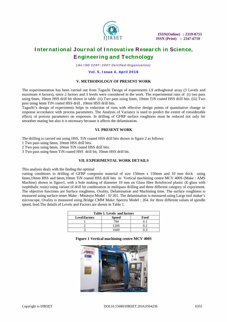
VII. EXPERIMENTAL WORK DETAILS This analysis deals with the finding the optimal cutting conditions in drilling of GFRP composite material of size 150mm x 150mm and 10 mm thick using 6mm,10mm HSS and 6mm,10mm TiN coated HSS drill bits in Vertical machining centre MCV 400S (Make : AMS Machine) shown in figure1, with a hole making of diameter 10 mm on Glass fibre Reinforced plastic (E-glass with isophthalic resin) using variant of drill bit combination in multipass drilling and three different category of experiment. The objective functions are Surface roughness, Ovality, Delamination and Machining time. The surface roughness is measured using surface tester Make : Mitutoyo Model : SJ 201. The delamination is measured using Large tool maker’s microscope, Ovality is measured using Bridge CMM Make: Spectra Model : 264. for three different values of spindle speed, feed.The details of Levels and Factors are shown in Table 1.
Table 1. Levels and factors Level/factors Speed Feed
1 790 0.1 2 1200 0.2 3 1600 0.3
Figure 1 Vertical machining centre MCV 400S
ISSN(Online) : 2319-8753 ISSN (Print) : 2347-6710
International Journal of Innovative Research in Science, Engineering and Technology
(An ISO 3297: 2007 Certified Organization)
Vol. 5, Issue 4, April 2016
Copyright to IJIRSET DOI:10.15680/IJIRSET.2016.0504236 6356
VIII. DATA ANALYSIS
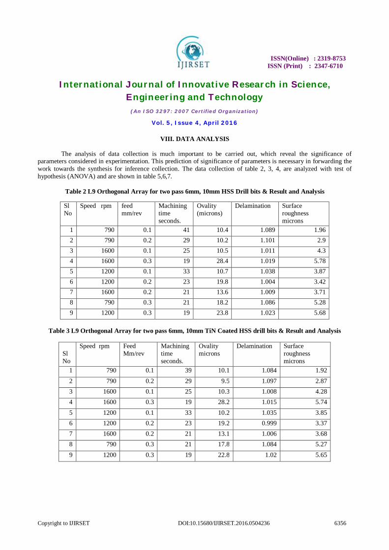
The analysis of data collection is much important to be carried out, which reveal the significance of parameters considered in experimentation. This prediction of significance of parameters is necessary in forwarding the work towards the synthesis for inference collection. The data collection of table 2, 3, 4, are analyzed with test of hypothesis (ANOVA) and are shown in table 5,6,7.
Table 2 L9 Orthogonal Array for two pass 6mm, 10mm HSS Drill bits & Result and Analysis
Sl No
Speed rpm feed mm/rev
Machining time seconds.
Ovality (microns)
Delamination Surface roughness microns
1 790 0.1 41 10.4 1.089 1.96 2 790 0.2 29 10.2 1.101 2.9 3 1600 0.1 25 10.5 1.011 4.3 4 1600 0.3 19 28.4 1.019 5.78 5 1200 0.1 33 10.7 1.038 3.87 6 1200 0.2 23 19.8 1.004 3.42 7 1600 0.2 21 13.6 1.009 3.71 8 790 0.3 21 18.2 1.086 5.28 9 1200 0.3 19 23.8 1.023 5.68
Table 3 L9 Orthogonal Array for two pass 6mm, 10mm TiN Coated HSS drill bits & Result and Analysis
Sl No
Speed rpm Feed Mm/rev
Machining time seconds.
Ovality microns
Delamination Surface roughness microns
1 790 0.1 39 10.1 1.084 1.92 2 790 0.2 29 9.5 1.097 2.87 3 1600 0.1 25 10.3 1.008 4.28 4 1600 0.3 19 28.2 1.015 5.74 5 1200 0.1 33 10.2 1.035 3.85 6 1200 0.2 23 19.2 0.999 3.37 7 1600 0.2 21 13.1 1.006 3.68 8 790 0.3 21 17.8 1.084 5.27 9 1200 0.3 19 22.8 1.02 5.65

ISSN(Online) : 2319-8753 ISSN (Print) : 2347-6710
International Journal of Innovative Research in Science, Engineering and Technology
(An ISO 3297: 2007 Certified Organization)
Vol. 5, Issue 4, April 2016
Copyright to IJIRSET DOI:10.15680/IJIRSET.2016.0504236 6357
Table 4 L9 Orthogonal Array for two pass 6mm TiN coated HSS & 10mm HSS drill bits & Result and Analysis
Sl No Speed rpm
feed mm/rev
Machining time seconds.
Ovality microns Delamination
Surface roughness microns
1 790 0.1 39 10.6 1.964 1.93 2 790 0.2 29 10.7 2.904 2.87 3 1600 0.1 25 10.6 4.305 4.27 4 1600 0.3 19 30.5 5.776 5.74 5 1200 0.1 33 10.5 3.875 3.85 6 1200 0.2 23 20.8 3.423 3.38 7 1600 0.2 21 14.1 3.715 3.68 8 790 0.3 21 20.1 5.286 5.26 9 1200 0.3 19 24.8 5.685 5.65
Table. 5 ANOVA results for two pass 6mm, 10mm HSS Drill Bits & Result and Analysis
From Table 5 it is obvious that the Machining time, Ovality, Delamination and Surface roughness is significant with cutting parameters Speed and Feed rate for two pass HSS drill at 95% confidence level with F –value. R – squared value for all the above responses are greater than 0.8 this shows that the fitness function holds good.
MAC HI NI NG TI ME OVALITY DELAMINATION SUR FA CE ROU GH NESS MO DE L 2 F I LINE AR LINE AR 2 F I S S 428.4816094 282.5127 0.0094379 10.363225 D O F 3 2 2 3 M S 142.8272031 141.2563 0.004719 3.4544085 F VAL UE 61.99963539 10.57006 10.941989 5.6169707 PROB>F 0 . 0 0 0 2 0. 0108 0 . 0 1 0 0 0 . 0 4 6 6 RESULT Significant significant Significant significant
R - SQ U A R ED 0.97382184 0.778925 0.7848227 0.7711766 S/N R A T I O 2 1 . 7 7 8 8 . 3 0 3 6 . 8 8 8 6 . 5 5 4
ISSN(Online) : 2319-8753 ISSN (Print) : 2347-6710
International Journal of Innovative Research in Science, Engineering and Technology
(An ISO 3297: 2007 Certified Organization)
Vol. 5, Issue 4, April 2016
Copyright to IJIRSET DOI:10.15680/IJIRSET.2016.0504236 6358
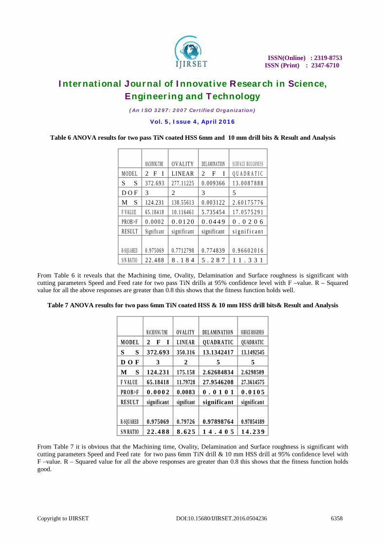
Table 6 ANOVA results for two pass TiN coated HSS 6mm and 10 mm drill bits & Result and Analysis
MACHINING TIME OVALITY DELAMINATION S U R F A C E R O U G H N E S S MODE L 2 F I LINEAR 2 F I Q U A D R A T I C S S 3 7 2 .6 9 3 277 .11225 0 .009366 1 3 . 0 0 8 7 8 8 8 D O F 3 2 3 5 M S 124.231 138 .55613 0 .003122 2 . 6 0 1 7 5 7 7 6 F VALUE 6 5 . 1 8 4 1 8 10 .116461 5 .735454 1 7 . 0 5 7 5 2 9 1 PROB>F 0 . 0 0 0 2 0 . 01 20 0 . 0 4 4 9 0 . 0 2 0 6 RESULT Signi fic an t signi fi cant significant s i g n i f i c a n t
R- SQ U A RE D 0 . 9 7 5 0 6 9 0 .7712798 0 .774839 0 . 9 6 6 0 2 0 1 6 S/N RA TIO 2 2 . 4 8 8 8 . 1 8 4 5 . 2 8 7 1 1 . 3 3 1
From Table 6 it reveals that the Machining time, Ovality, Delamination and Surface roughness is significant with cutting parameters Speed and Feed rate for two pass TiN drills at 95% confidence level with F –value. R – Squared value for all the above responses are greater than 0.8 this shows that the fitness function holds well.
Table 7 ANOVA results for two pass 6mm TiN coated HSS & 10 mm HSS drill bits& Result and Analysis
M A C H I N I N G T I M E OV A L I T Y DEL A MIN AT IO N S URFACE ROUGH NES S MODEL 2 F I LIN EAR QUADR ATIC QUAD RATIC S S 372.693 350.316 13.1342417 13.1492545 D O F 3 2 5 5 M S 124.231 175.158 2.62684834 2.6298509 F V A L U E 65.18418 11.79728 27.9546208 27.3614575 PR OB>F 0 . 00 0 2 0.0083 0 . 0 1 0 1 0 . 0 1 0 5 RESU LT significant significant significant significant
R -SQ U A R E D 0.975069 0.79726 0.97898764 0.97854189 S/N RATIO 2 2 . 4 8 8 8 . 62 5 1 4 . 4 0 5 1 4 . 2 3 9
From Table 7 it is obvious that the Machining time, Ovality, Delamination and Surface roughness is significant with cutting parameters Speed and Feed rate for two pass 6mm TiN drill & 10 mm HSS drill at 95% confidence level with F –value. R – Squared value for all the above responses are greater than 0.8 this shows that the fitness function holds good.
ISSN(Online) : 2319-8753 ISSN (Print) : 2347-6710
International Journal of Innovative Research in Science, Engineering and Technology
(An ISO 3297: 2007 Certified Organization)
Vol. 5, Issue 4, April 2016
Copyright to IJIRSET DOI:10.15680/IJIRSET.2016.0504236 6359
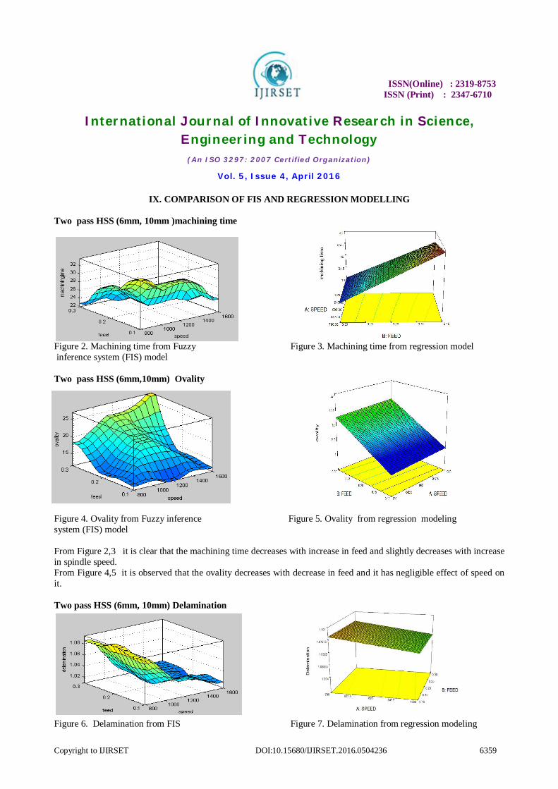
IX. COMPARISON OF FIS AND REGRESSION MODELLING Two pass HSS (6mm, 10mm )machining time
Figure 2. Machining time from Fuzzy Figure 3. Machining time from regression model inference system (FIS) model Two pass HSS (6mm,10mm) Ovality Figure 4. Ovality from Fuzzy inference Figure 5. Ovality from regression modeling system (FIS) model From Figure 2,3 it is clear that the machining time decreases with increase in feed and slightly decreases with increase in spindle speed. From Figure 4,5 it is observed that the ovality decreases with decrease in feed and it has negligible effect of speed on it. Two pass HSS (6mm, 10mm) Delamination
Figure 6. Delamination from FIS Figure 7. Delamination from regression modeling

ISSN(Online) : 2319-8753 ISSN (Print) : 2347-6710
International Journal of Innovative Research in Science, Engineering and Technology
(An ISO 3297: 2007 Certified Organization)
Vol. 5, Issue 4, April 2016
Copyright to IJIRSET DOI:10.15680/IJIRSET.2016.0504236 6360
From Figure 6,7 it reveals that the delamination decreases with increase in spindle speed and has negligible effect of feed on it. Two pass HSS (6mm, 10mm)surface roughness
Figure 8. Surface roughness from FIS Figure 9 Surface roughness from regression modeling From Figure 8,9 it shows that the surface roughness decreases with decrease in feed and it has negligible effect of speed Two pass TiN (6mm, 10mm)Machining time
Fig 10 machining time from FIS Figure 11. Machining time from regression modeling From Figure 10, 11 it is clear that the machining time decreases with increase in feed and slightly decreases with speed.
ISSN(Online) : 2319-8753 ISSN (Print) : 2347-6710
International Journal of Innovative Research in Science, Engineering and Technology
(An ISO 3297: 2007 Certified Organization)
Vol. 5, Issue 4, April 2016
Copyright to IJIRSET DOI:10.15680/IJIRSET.2016.0504236 6361
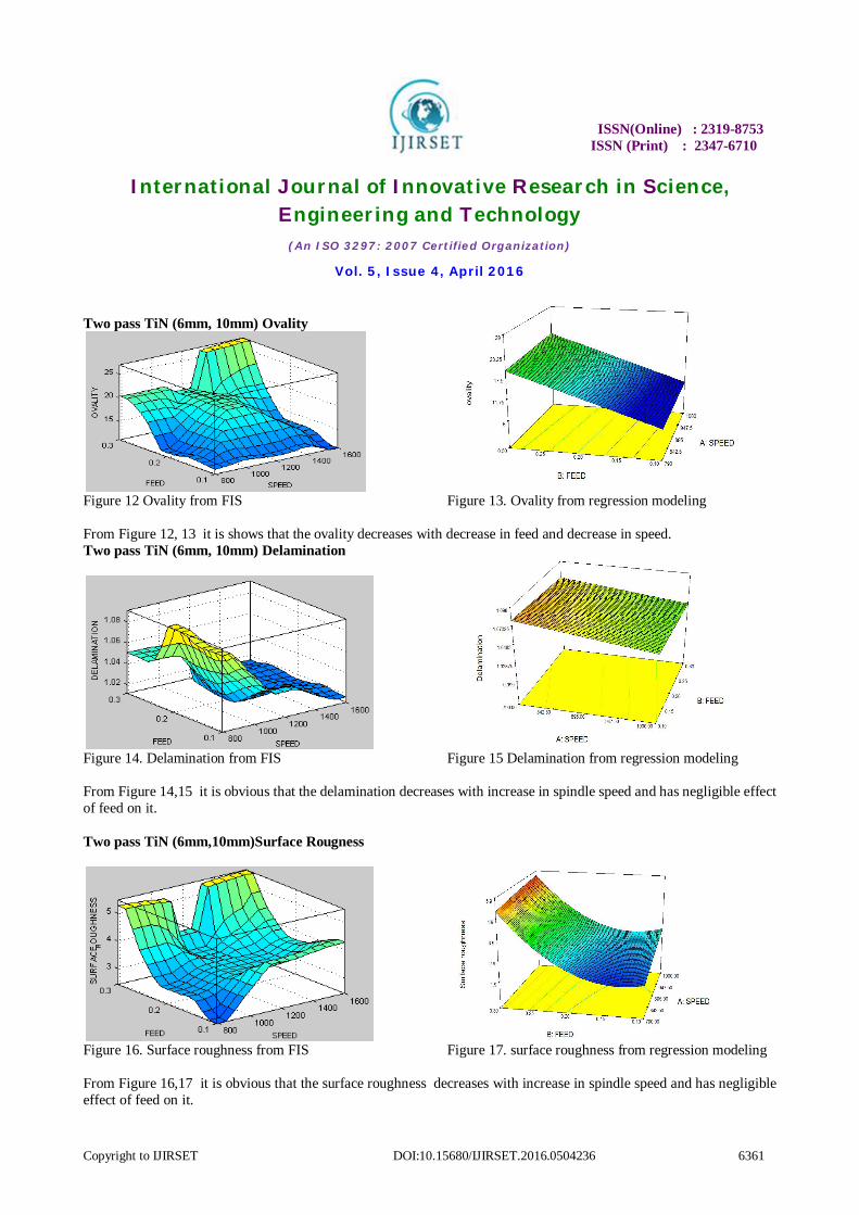
Two pass TiN (6mm, 10mm) Ovality
Figure 12 Ovality from FIS Figure 13. Ovality from regression modeling From Figure 12, 13 it is shows that the ovality decreases with decrease in feed and decrease in speed. Two pass TiN (6mm, 10mm) Delamination
Figure 14. Delamination from FIS Figure 15 Delamination from regression modeling From Figure 14,15 it is obvious that the delamination decreases with increase in spindle speed and has negligible effect of feed on it. Two pass TiN (6mm,10mm)Surface Rougness
Figure 16. Surface roughness from FIS Figure 17. surface roughness from regression modeling From Figure 16,17 it is obvious that the surface roughness decreases with increase in spindle speed and has negligible effect of feed on it.

ISSN(Online) : 2319-8753 ISSN (Print) : 2347-6710
International Journal of Innovative Research in Science, Engineering and Technology
(An ISO 3297: 2007 Certified Organization)
Vol. 5, Issue 4, April 2016
Copyright to IJIRSET DOI:10.15680/IJIRSET.2016.0504236 6362
Two pass Tin and HSS (6mm,10mm) machining time
Figure 18 Machining time from FIS Figure 19. Machining time from regression modeling From Figure 18,19 it is clear that the machining time decreases with increase in feed and slightly decreases with speed. Two pass Tin and HSS (6mm, 10mm) ovality
Figure 20. Ovality from FIS Ffigure 21. ovality from regression modeling. From Figure 20,21 it is obvious that the ovality decreases with decrease in feed and slightly decreases with decrease in speed. Ovality is maximum at the highest feed rate. Two pass TiN and HSS (6mm, 10mm) Delamination
Figure 22. Delamination from FIS Figure 23. Delamination from regression modeling From Figure 22,23 it is clear that the delamination gradually decreases with increase in spindle speed and has negligible effect of feed on it.
ISSN(Online) : 2319-8753 ISSN (Print) : 2347-6710
International Journal of Innovative Research in Science, Engineering and Technology
(An ISO 3297: 2007 Certified Organization)
Vol. 5, Issue 4, April 2016
Copyright to IJIRSET DOI:10.15680/IJIRSET.2016.0504236 6363
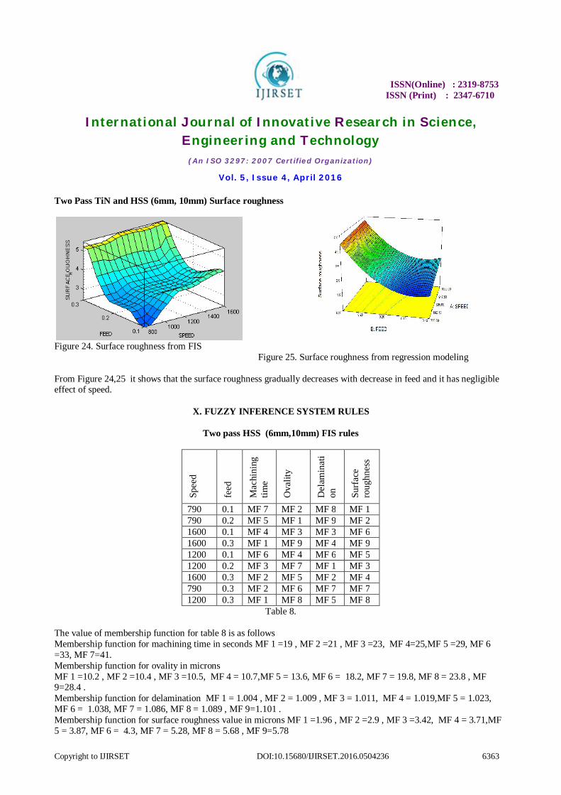
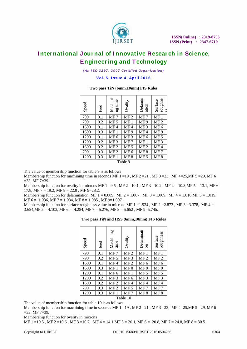
Two Pass TiN and HSS (6mm, 10mm) Surface roughness
Figure 24. Surface roughness from FIS
Figure 25. Surface roughness from regression modeling
From Figure 24,25 it shows that the surface roughness gradually decreases with decrease in feed and it has negligible effect of speed.
X. FUZZY INFERENCE SYSTEM RULES
Two pass HSS (6mm,10mm) FIS rules
Spee
d
feed
Mac
hini
ng
time
Ova
lity
Del
amin
ati
on
Surf
ace
roug
hnes
s
790 0.1 MF 7 MF 2 MF 8 MF 1 790 0.2 MF 5 MF 1 MF 9 MF 2 1600 0.1 MF 4 MF 3 MF 3 MF 6 1600 0.3 MF 1 MF 9 MF 4 MF 9 1200 0.1 MF 6 MF 4 MF 6 MF 5 1200 0.2 MF 3 MF 7 MF 1 MF 3 1600 0.3 MF 2 MF 5 MF 2 MF 4 790 0.3 MF 2 MF 6 MF 7 MF 7 1200 0.3 MF 1 MF 8 MF 5 MF 8
Table 8. The value of membership function for table 8 is as follows Membership function for machining time in seconds MF 1 =19 , MF 2 =21 , MF 3 =23, MF 4=25,MF 5 =29, MF 6 =33, MF 7=41. Membership function for ovality in microns MF 1 =10.2 , MF 2 =10.4 , MF 3 =10.5, MF 4 = 10.7,MF 5 = 13.6, MF 6 = 18.2, MF 7 = 19.8, MF 8 = 23.8 , MF 9=28.4 . Membership function for delamination MF 1 = 1.004 , MF 2 = 1.009 , MF 3 = 1.011, MF 4 = 1.019,MF 5 = 1.023, MF 6 = 1.038, MF 7 = 1.086, MF 8 = 1.089 , MF 9=1.101 . Membership function for surface roughness value in microns MF 1 =1.96 , MF 2 =2.9 , MF 3 =3.42, MF 4 = 3.71,MF 5 = 3.87, MF 6 = 4.3, MF 7 = 5.28, MF 8 = 5.68 , MF 9=5.78
ISSN(Online) : 2319-8753 ISSN (Print) : 2347-6710
International Journal of Innovative Research in Science, Engineering and Technology
(An ISO 3297: 2007 Certified Organization)
Vol. 5, Issue 4, April 2016
Copyright to IJIRSET DOI:10.15680/IJIRSET.2016.0504236 6364
Two pass TiN (6mm,10mm) FIS Rules
Spee
d
feed
Mac
hini
ng ti
me
Ova
lity
Del
amin
atio
n
Surf
ace
roug
hne
ss
790 0.1 MF 7 MF 2 MF 7 MF 1 790 0.2 MF 5 MF 1 MF 9 MF 2 1600 0.1 MF 4 MF 4 MF 3 MF 6 1600 0.3 MF 1 MF 9 MF 4 MF 9 1200 0.1 MF 6 MF 3 MF 6 MF 5 1200 0.2 MF 3 MF 7 MF 1 MF 3 1600 0.2 MF 2 MF 5 MF 2 MF 4 790 0.3 MF 2 MF 6 MF 8 MF 7 1200 0.3 MF 1 MF 8 MF 5 MF 8
Table 9
The value of membership function for table 9 is as follows Membership function for machining time in seconds MF 1 =19 , MF 2 =21 , MF 3 =23, MF 4=25,MF 5 =29, MF 6 =33, MF 7=39. Membership function for ovality in microns MF 1 =9.5 , MF 2 =10.1 , MF 3 =10.2, MF 4 = 10.3,MF 5 = 13.1, MF 6 = 17.8, MF 7 = 19.2, MF 8 = 22.8 , MF 9=28.2. Membership function for delamination MF 1 = 0.009 , MF 2 = 1.007 , MF 3 = 1.009, MF 4 = 1.016,MF 5 = 1.019, MF 6 = 1.036, MF 7 = 1.084, MF 8 = 1.085 , MF 9=1.097 . Membership function for surface roughness value in microns MF 1 =1.924 , MF 2 =2.873 , MF 3 =3.378, MF 4 = 3.684,MF 5 = 4.102, MF 6 = 4.284, MF 7 = 5.276, MF 8 = 5.652 , MF 9=5.745.
Two pass TiN and HSS (6mm,10mm) FIS Rules
Spee
d
feed
Mac
hini
ng
time
Ova
lity
Del
amin
ati
on
Surf
ace
roug
hnes
s
790 0.1 MF 7 MF 2 MF 1 MF 1 790 0.2 MF 5 MF 3 MF 2 MF 2 1600 0.1 MF 4 MF 2 MF 6 MF 6 1600 0.3 MF 1 MF 8 MF 9 MF 9 1200 0.1 MF 6 MF 1 MF 5 MF 5 1200 0.2 MF 3 MF 6 MF 3 MF 3 1600 0.2 MF 2 MF 4 MF 4 MF 4 790 0.3 MF 2 MF 5 MF 7 MF 7 1200 0.3 MF 1 MF 7 MF 8 MF 8
Table 10 The value of membership function for table 10 is as follows Membership function for machining time in seconds MF 1 =19 , MF 2 =21 , MF 3 =23, MF 4=25,MF 5 =29, MF 6 =33, MF 7=39. Membership function for ovality in microns MF 1 =10.5 , MF 2 =10.6 , MF 3 =10.7, MF 4 = 14.1,MF 5 = 20.1, MF 6 = 20.8, MF 7 = 24.8, MF 8 = 30.5.
ISSN(Online) : 2319-8753 ISSN (Print) : 2347-6710
International Journal of Innovative Research in Science, Engineering and Technology
(An ISO 3297: 2007 Certified Organization)
Vol. 5, Issue 4, April 2016
Copyright to IJIRSET DOI:10.15680/IJIRSET.2016.0504236 6365
Membership function for delamination MF 1 = 1.965 , MF 2 = 2.905 , MF 3 = 3.342, MF 4 = 3.715,MF 5 = 3.875, MF 6 = 4.305, MF 7 = 5.286, MF 8 = 5.685 , MF 9=5.776 . Membership function for surface roughness value in microns MF 1 =1.93 , MF 2 =2.87 , MF 3 =3.38, MF 4 = 3.68,MF 5 = 3.85, MF 6 = 4.27, MF 7 = 5.26, MF 8 = 5.65 , MF 9=5.74.
XI. RESULTS AND DISCUSSION In this work from all cases, multi pass drilling carried using HSS, TiN drill bits
1. The Machining time decreases with increase in speed and increase in feed. Minimum machining time can be obtained by increasing speed and feed.
2. The ovality decreases with decrease in feed and decrease in speed. Minimum ovality can be obtained by reducing the feed and speed.
3. The Delamination decreases with increase in speed and decrease in feed. In case of multi pass 6 mm TiN, 10 mm HSS the delamination decreases gradually with increase in speed and decrease in feed. However minimum delamination can be achieved by increased spindle speed and decreased feed.
4. Most probably the surface roughness decreases with decrease in feed and the effect of speed is negligible on it.
XII. CONCLUSION From all figures however the inferences obtained from FIS and Regression model are seems to be similar, the detail of perception from FIS provides higher vicinity of variation in the response with respect to change in process parameters. ie., the the graphical inference from the regression model simply represents the inferences in sharp and crisp form of straight line, whereas from the FIS it is more detailed for each and every point of variation of process parameter and the response (the graphical representation is in curve form) such a way the perception of prediction is so fine. So the Fuzzy modeling and Fuzzy Inference system works better for analyzing inference from graphical surface plots than Regression modeling inference system
REFERENCES [1] Eda Okutan et al “A Study on the Derivation of Parametric Cutting Force Equations in Drilling of GFRP Composites” , Journal of Mechanical Engineering,Vol 59, No.2, 2013 , pp. 97-105. [2] B. Ramesh et al “Optimization of Ovality On Drilling Glass fiber Reinforced Plastic Compoosite With Coated Tungsten Carbide Tool”, International Journal of Innovative Research in Sciences, Engineering & Technology, Vol. 2, 7 July 2013, pp. 2801-2809. [3] K. Glasin et al, “An experimental study on drilling of unidirectional GLARE fibre metal laminates”, ELSEVIER, Composite structures Vol. 133, 2015, Pp 794 – 808. [4] Shiba narayan sahu et al, “Thrust, torque analyses and optimisation in microdrilling of GFRP using full factorial design integrated CNSGA – II algorithm”, ELSEVIER, Procedia Material Science Vol 6, 2014, pp. 967-974. [5]Hari Vasudevan et al, “Multiobjective optimisation of drilling charecteristics for NEMA G-11 GFRP/ EPOXY composite using Desirability coupled with Taguchi Method”, ELSEVIER,Procedia Engineering, Vol. 97,2014, pp. 522 – 530. [6] Vikas Sonkar et al, “Multi objective optimisation in drilling of GFRP composites . A degree of similarity approach.”, ELSEVIER, Procedia material science ,Vol 6, 2014, pp. 538-543. [7] Sunil Hansda et al., “Optimising multi characteristics in drilling of GFRP composite using utility concept with Taguchi’s approach” , ELSEVIER, Procedia material science ,Vol. 6, 2014, pp. 1476-1488. [8] Pandu R. Vundavilli et al, “Evolutionary and swarm based optimisation of turning of GFRP composites using PCD tooling”, Academic journal of manufacturing engineering Vol 11, No. 1, 2013, pp. 125-130. [9] Vinod Kumar Vankanti et al, “Optimisation of process parameters in drilling of GFRP composite using Taguchi method”, ELSEVIER, Journal of Material Research and technology, 2014, Vol 3, No. 1, pp.35-41. [10] Panda et al, “Optimisation of bone drilling using Taguchi methodology coupled with fuzzy based desirability function approach”, SPRINGER , J Iintell Manuf, October 2013, published online. [11] MAJ .Bosco et al, “ Influencee of machining parameters on delamination in drilling of GFRP armour steel sandwich plates”, ELSEVIER Procedia engineering, Vol 51 , 2013, Pp 758 -763. [12] Tom Sunny Et al, “Experimental studies on effect of process parameters on delamination in drilling GFRp composites using Taguchi method”, ELSEVIER, Procedia Material Science, Vol 6, 2014 , pp. 1131-1142.