Embed Size (px)
Citation preview
Vission 20/20 Retrofit Instructions

3ViSSion® 20/20 Retrofi t Instructions • 35391SCRF
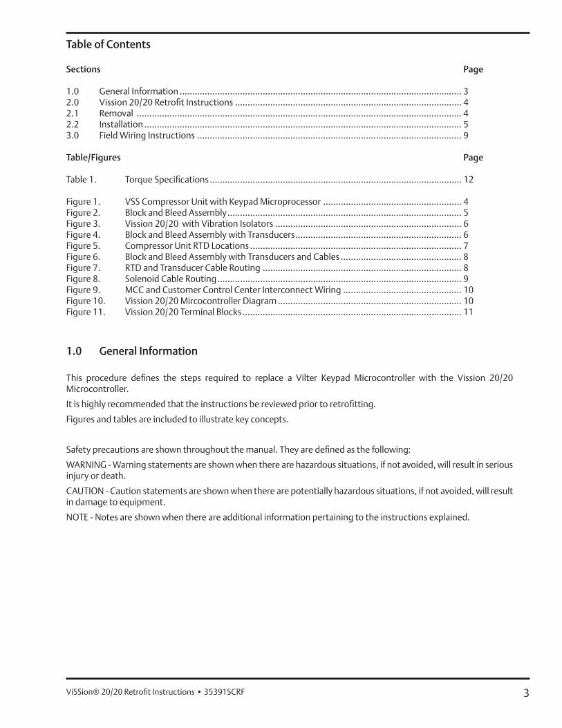
Table of Contents
Sections Page
1.0 General Information ................................................................................................................ 32.0 Vission 20/20 Retrofi t Instructions .......................................................................................... 42.1 Removal ................................................................................................................................. 42.2 Installation .............................................................................................................................. 53.0 Field Wiring Instructions ......................................................................................................... 9
Table/Figures Page
Table 1. Torque Specifi cations .................................................................................................... 12
Figure 1. VSS Compressor Unit with Keypad Microprocessor ....................................................... 4Figure 2. Block and Bleed Assembly ............................................................................................. 5Figure 3. Vission 20/20 with Vibration Isolators .......................................................................... 6Figure 4. Block and Bleed Assembly with Transducers .................................................................. 6Figure 5. Compressor Unit RTD Locations .................................................................................... 7Figure 6. Block and Bleed Assembly with Transducers and Cables ................................................ 8Figure 7. RTD and Transducer Cable Routing ............................................................................... 8Figure 8. Solenoid Cable Routing ................................................................................................. 9Figure 9. MCC and Customer Control Center Interconnect Wiring ............................................... 10Figure 10. Vission 20/20 Mircocontroller Diagram ......................................................................... 10Figure 11. Vission 20/20 Terminal Blocks ....................................................................................... 11
1.0 General Information
This procedure defi nes the steps required to replace a Vilter Keypad Microcontroller with the Vission 20/20 Microcontroller.
It is highly recommended that the instructions be reviewed prior to retrofi tting.
Figures and tables are included to illustrate key concepts.
Safety precautions are shown throughout the manual. They are defi ned as the following:
WARNING - Warning statements are shown when there are hazardous situations, if not avoided, will result in serious injury or death.
CAUTION - Caution statements are shown when there are potentially hazardous situations, if not avoided, will result in damage to equipment.
NOTE - Notes are shown when there are additional information pertaining to the instructions explained.
4 ViSSion® 20/20 Retrofi t Instructions • 35391SCRF
2.0 Vission 20/20 Retrofi t Instructions
This procedure defi nes the steps required to replace a Vilter Keypad Microcontroller with the Vission 20/20 Microcontroller.
2.1 Removal
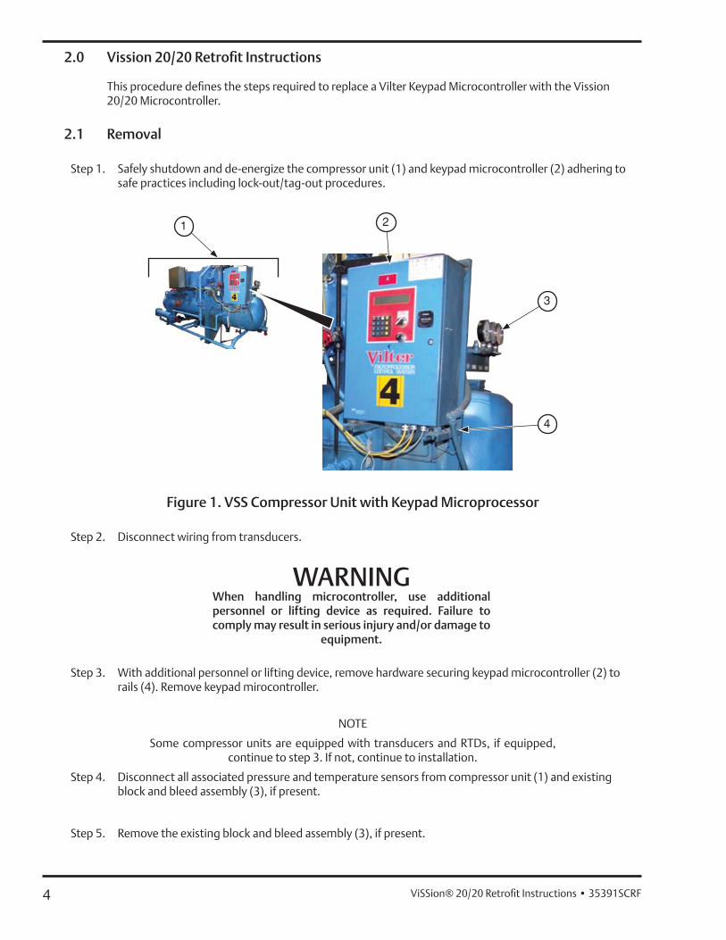
Step 1. Safely shutdown and de-energize the compressor unit (1) and keypad microcontroller (2) adhering to safe practices including lock-out/tag-out procedures.
Figure 1. VSS Compressor Unit with Keypad Microprocessor
Step 2. Disconnect wiring from transducers.
WARNINGWhen handling microcontroller, use additionalpersonnel or lifting device as required. Failure tocomply may result in serious injury and/or damage to
equipment.
Step 3. With additional personnel or lifting device, remove hardware securing keypad microcontroller (2) to rails (4). Remove keypad mirocontroller.
NOTE
Some compressor units are equipped with transducers and RTDs, if equipped, continue to step 3. If not, continue to installation.
Step 4. Disconnect all associated pressure and temperature sensors from compressor unit (1) and existing block and bleed assembly (3), if present.
Step 5. Remove the existing block and bleed assembly (3), if present.
5ViSSion® 20/20 Retrofi t Instructions • 35391SCRF
2.2 Installation
NOTE
Torque all hardware according to torque table specifi cations, see Table 1.
NOTE
Modifi cation to rails may be required to support and properly align Vission 20/20 microcontroller and block and bleed assembly. Follow standard practices for
weldment and fabrication procedures.
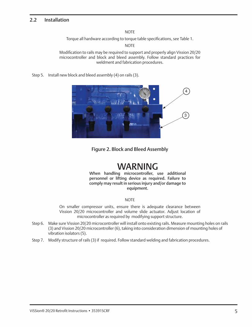
Step 5. Install new block and bleed assembly (4) on rails (3).
Figure 2. Block and Bleed Assembly
WARNINGWhen handling microcontroller, use additionalpersonnel or lifting device as required. Failure tocomply may result in serious injury and/or damage to
equipment.
NOTE
On smaller compressor units, ensure there is adequate clearance between Vission 20/20 microcontroller and volume slide actuator. Adjust location of
microcontroller as required by modifying support structure.
Step 6. Make sure Vission 20/20 microcontroller will install onto existing rails. Measure mounting holes on rails (3) and Vission 20/20 microcontroller (6), taking into consideration dimension of mounting holes of vibration isolators (5).
Step 7. Modify structure of rails (3) if required. Follow standard welding and fabrication procedures.
6 ViSSion® 20/20 Retrofi t Instructions • 35391SCRF
Step 8. Install hardware to secure new vibration isolators (5) to mounting holes of Vission 20/20 microcontroller (6).
Figure 3. Vission 20/20 with Vibration Isolators
Step 10. With additional personnel or lifting device, install hardware to secure Vission 20/20 microcontroller (6)with vibration isolators (5) to rails (3).
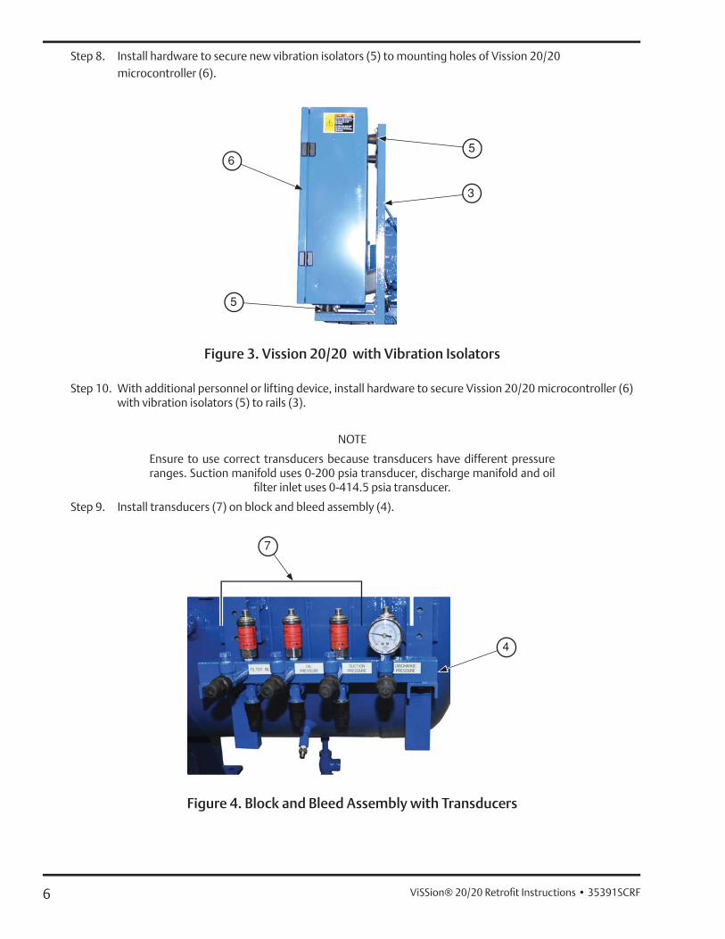
NOTE
Ensure to use correct transducers because transducers have different pressure ranges. Suction manifold uses 0-200 psia transducer, discharge manifold and oil
fi lter inlet uses 0-414.5 psia transducer.
Step 9. Install transducers (7) on block and bleed assembly (4).
Figure 4. Block and Bleed Assembly with Transducers
7ViSSion® 20/20 Retrofi t Instructions • 35391SCRF
NOTE
Stainless steel tubing is not provided in a retrofi t kit.
Step 10. Route stainless steel tubing from suction manifold, discharge manifold and oil fi lter inlet lines. If existing tubing is not reusable then cables can be secured to block and bleed assembly (4).
NOTE
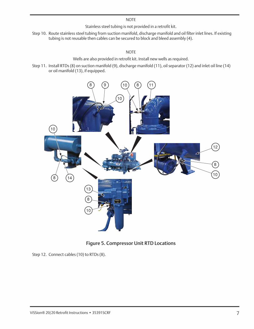
Wells are also provided in retrofi t kit. Install new wells as required.
Step 11. Install RTDs (8) on suction manifold (9), discharge manifold (11), oil separator (12) and inlet oil line (14) or oil manifold (13), if equipped.
Figure 5. Compressor Unit RTD Locations
Step 12. Connect cables (10) to RTDs (8).
8 ViSSion® 20/20 Retrofi t Instructions • 35391SCRF
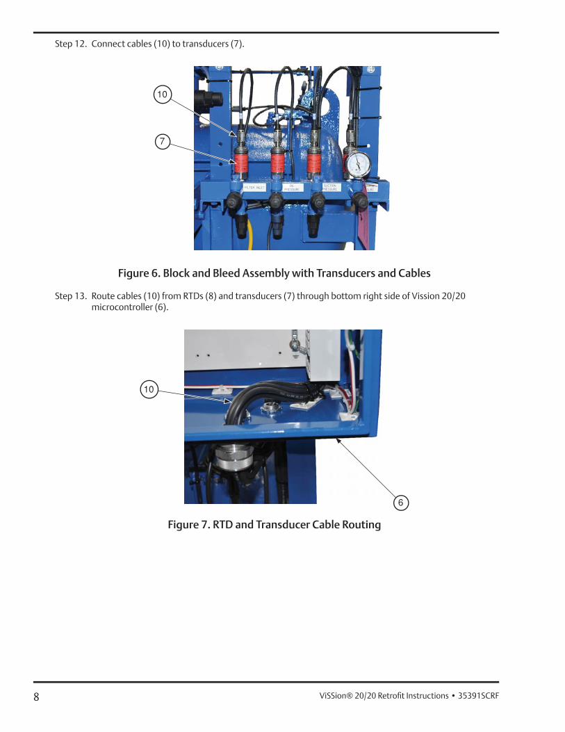
Step 12. Connect cables (10) to transducers (7).
Figure 6. Block and Bleed Assembly with Transducers and Cables
Step 13. Route cables (10) from RTDs (8) and transducers (7) through bottom right side of Vission 20/20 microcontroller (6).
Figure 7. RTD and Transducer Cable Routing
9ViSSion® 20/20 Retrofi t Instructions • 35391SCRF
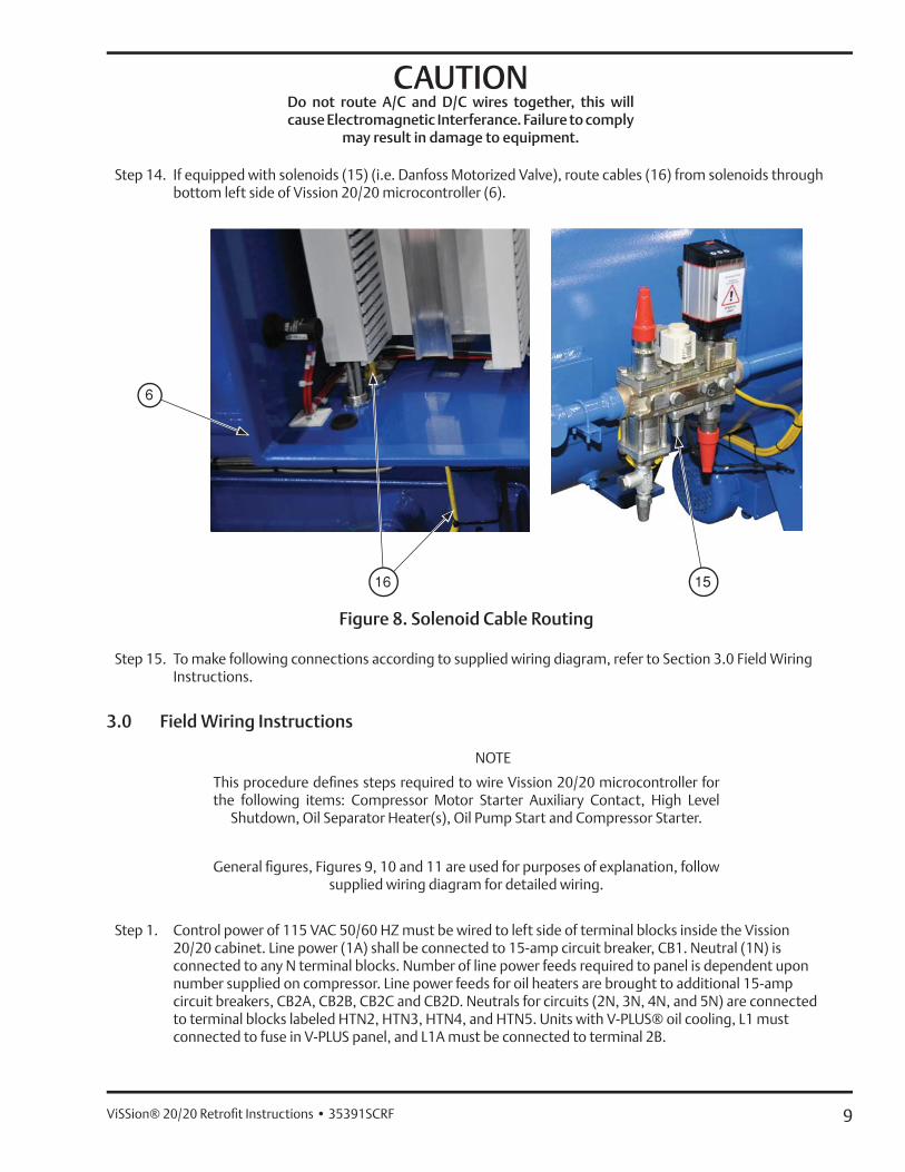
CAUTIONDo not route A/C and D/C wires together, this willcause Electromagnetic Interferance. Failure to comply
may result in damage to equipment.
Step 14. If equipped with solenoids (15) (i.e. Danfoss Motorized Valve), route cables (16) from solenoids through bottom left side of Vission 20/20 microcontroller (6).
Figure 8. Solenoid Cable Routing
Step 15. To make following connections according to supplied wiring diagram, refer to Section 3.0 Field Wiring Instructions.
3.0 Field Wiring Instructions
NOTE
This procedure defi nes steps required to wire Vission 20/20 microcontroller for the following items: Compressor Motor Starter Auxiliary Contact, High Level
Shutdown, Oil Separator Heater(s), Oil Pump Start and Compressor Starter.
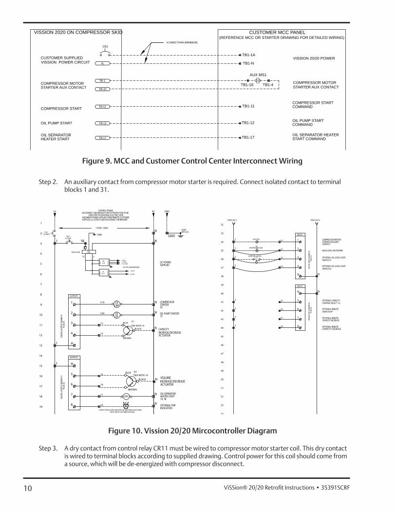
General fi gures, Figures 9, 10 and 11 are used for purposes of explanation, follow supplied wiring diagram for detailed wiring.
Step 1. Control power of 115 VAC 50/60 HZ must be wired to left side of terminal blocks inside the Vission 20/20 cabinet. Line power (1A) shall be connected to 15-amp circuit breaker, CB1. Neutral (1N) is connected to any N terminal blocks. Number of line power feeds required to panel is dependent upon number supplied on compressor. Line power feeds for oil heaters are brought to additional 15-amp circuit breakers, CB2A, CB2B, CB2C and CB2D. Neutrals for circuits (2N, 3N, 4N, and 5N) are connected to terminal blocks labeled HTN2, HTN3, HTN4, and HTN5. Units with V-PLUS® oil cooling, L1 must connected to fuse in V-PLUS panel, and L1A must be connected to terminal 2B.
10 ViSSion® 20/20 Retrofi t Instructions • 35391SCRF
Step 2. An auxiliary contact from compressor motor starter is required. Connect isolated contact to terminal blocks 1 and 31.
19
18
17
16
14
15
13
9
12
11
10
8
7
6
4
5
3
2
1
115VAC / 60HZDOORGND LUG
1A
DC POWER SUPPLIES
N1CONTROL POWERDISCONNECT AND BRANCH CIRCUIT PROTECTION TO BE
SIZED PER THE NATIONAL ELECTRIC CODE.INCOMING POWER SUPPLIED FROM REMOTE CUSTOMER SUPPLIED UL LISTED FUSED DISCONNECT OR BREAKER
15 AMPSCB 1
SW 1E-STOP
LINELOADEMI FILTER
TO CPU BASEBOARD
OUTPUTS
13
14
16
15
OIL SEPARATOR HEATER START74, 78
17
18 HHH OPTIONAL TRIP INDICATION
OUTPUT CAN ALSO BE USED WITH AN INDICATING LIGHT, HORN, OR PLC INPUT (CUSTOMER SUPPLIED)
GND
DIGI
TAL O
UTPU
T: BO
ARD
#1
PLUG
X1
DIGI
TAL O
UTPU
T: BO
ARD
#1
PLUG
X2
INPU
T
1C 2
OU
TPU
T +5VDC+12VDC5/12 COM
GND
OUTPUTS
N
N
1B1GND
RD-35-A
CRHA1 A2
1
1
N
N
N
N
N
H
5
6
7
8
H
4
3
2
1
RS-50-24
OU
TPU
T
INPU
T +24VDC
24 COM
COMPRESSOR STARTER70
OIL PUMP STARTER73
50
49
48
47
46
44
45
43
42
41
40
32
33
35
34
36
37
38
39
51
52
53
54
FROM LINE 31 FROM LINE 31
31
32
33
34
AUX MS1
HLSHUTDOWN AUX
COMPRESSOR MOTOR STARTER AUXILIARY CONTACT
HIGH LEVEL SHUTDOWN
OPTIONAL OIL LEVEL FLOAT SWITCH #1
OPTIONAL OIL LEVEL FLOAT SWITCH #2
OPTIONAL REMOTE CAPAPCITY DECREASE
OPTIONAL REMOTE CAPACITY INCREASE
OPTIONAL REMOTE START/STOP
OPTIONAL CAPACITY CONTROL SELECT 1/2
38
37
36
35
DIGI
TAL I
NPUT
: BOA
RD #3
PL
UG X
1DI
GITA
L INP
UT: B
OARD
#3
PLUG
X2
INPUTS
INPUTS
1
1
1
1
1
1
1
1
N
N
8
7
6
5
N
1
2
3
4
N
N
CROP
CRCMP
11A
12A
*SEE NOTE 10
A1
A2*SEE NOTE 10
BLACK
BLUE
BROWN
BLUE
BLACK
VOLUME INCREASE/DECREASE ACTUATOR
CAPACITY INCREASE/DECREASE ACTUATOR
BROWN
LOW OIL LEVELLS1
Figure 10. Vission 20/20 Mircocontroller Diagram
Step 3. A dry contact from control relay CR11 must be wired to compressor motor starter coil. This dry contact is wired to terminal blocks according to supplied drawing. Control power for this coil should come from a source, which will be de-energized with compressor disconnect.
VISSION 2020 ON COMPRESSOR SKID CUSTOMER MCC PANEL(REFERENCE MCC OR STARTER DRAWING FOR DETAILED WIRING)
OIL PUMP START
COMPRESSOR MOTOR STARTER AUX CONTACT
OIL SEPARATOR HEATER START
AUX MS1
COMPRESSOR MOTOR STARTER AUX CONTACT
TB-1
TB-31
CUSTOMER SUPPLIED VISSION POWER CIRCUIT N
OIL PUMP STARTCOMMAND
OIL SEPARATOR HEATER START COMMAND
COMPRESSOR STARTCOMPRESSOR STARTCOMMAND
CB1
TB1-1A
TB1-N
TB1-18 TB1-4
TB1-11
TB1-12
TB1-17
TB-11
TB-12
TB-17
VISSION 20/20 POWER
#12AWG THHN (MINIMUM)
Figure 9. MCC and Customer Control Center Interconnect Wiring
11ViSSion® 20/20 Retrofi t Instructions • 35391SCRF
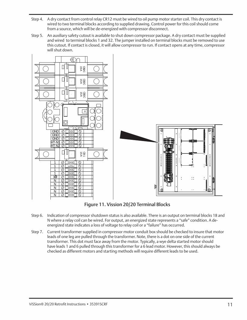
Step 4. A dry contact from control relay CR12 must be wired to oil pump motor starter coil. This dry contact is wired to two terminal blocks according to supplied drawing. Control power for this coil should come from a source, which will be de-energized with compressor disconnect.
Step 5. An auxiliary safety cutout is available to shut down compressor package. A dry contact must be supplied and wired to terminal blocks 1 and 32. The jumper installed on terminal blocks must be removed to use this cutout. If contact is closed, it will allow compressor to run. If contact opens at any time, compressor will shut down.
GNDGNDGND
1
HT-N2
CBA15 2C
CBA15
1CBA15 2C
HT-N1
CBA15 2C
DIGI
TAL W
IRIN
G
CUST
OMER
DIG
ITAL W
IRIN
G
CUST
OMER
ANA
LOG
WIR
ING
C5
5
OPE
N
C4
4321
GNDGNDGND
111111BNNNNN1112131415161718
2827262524232221
3132333435363738
X1
X2
X3
X4
X5
X1
X2
X3
X4
X5
ANAL
OG IN
PUT B
OARD
#7AN
ALOG
INPU
T BOA
RD #6
DIGI
TAL I
NPUT
BOA
RD #3
DIGI
TAL O
UTPU
T BOA
RD #2
DIGI
TAL O
UTPU
T BOA
RD #1
HT-N2
CBA15 2C
CBA15
1CBA15 2C
HT-N1
CBA15 2C
ANAL
OG O
UTPU
T BOA
RD #1
0
45464748
1111BNNNNN
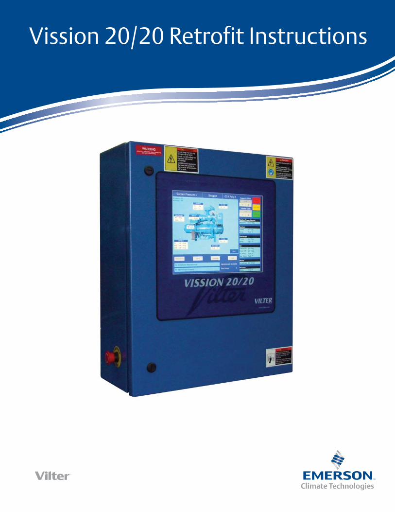
Figure 11. Vission 20/20 Terminal Blocks
Step 6. Indication of compressor shutdown status is also available. There is an output on terminal blocks 18 and N where a relay coil can be wired. For output, an energized state represents a “safe” condition. A de-energized state indicates a loss of voltage to relay coil or a “failure” has occurred.
Step 7. Current transformer supplied in compressor motor conduit box should be checked to insure that motor leads of one leg are pulled through the transformer. Note, there is a dot on one side of the current transformer. This dot must face away from the motor. Typically, a wye delta started motor should have leads 1 and 6 pulled through this transformer for a 6 lead motor. However, this should always be checked as different motors and starting methods will require different leads to be used.
12 ViSSion® 20/20 Retrofi t Instructions • 35391SCRF
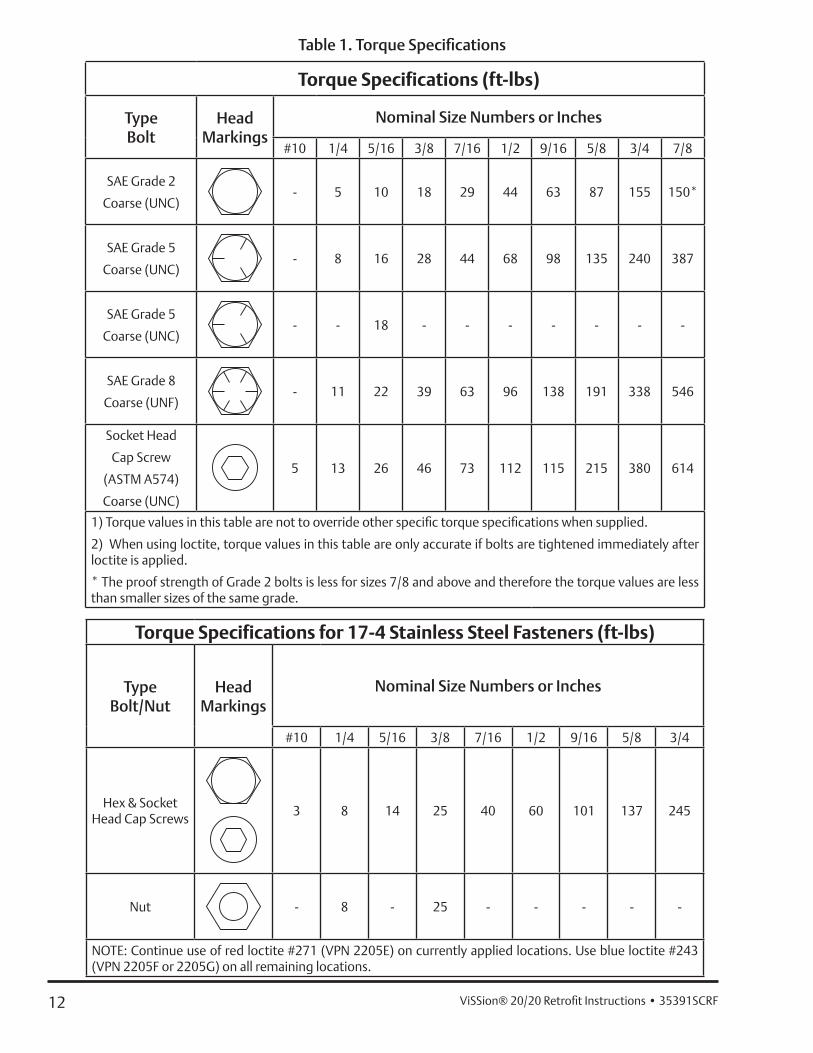
Torque Specifications (ft-lbs)
TypeBolt
HeadMarkings
Nominal Size Numbers or Inches
#10 1/4 5/16 3/8 7/16 1/2 9/16 5/8 3/4 7/8
SAE Grade 2
Coarse (UNC)- 5 10 18 29 44 63 87 155 150*
SAE Grade 5
Coarse (UNC)- 8 16 28 44 68 98 135 240 387
SAE Grade 5
Coarse (UNC)- - 18 - - - - - - -
SAE Grade 8
Coarse (UNF)- 11 22 39 63 96 138 191 338 546
Socket Head
Cap Screw
(ASTM A574)
Coarse (UNC)
5 13 26 46 73 112 115 215 380 614
1) Torque values in this table are not to override other specifi c torque specifi cations when supplied.
2) When using loctite, torque values in this table are only accurate if bolts are tightened immediately after loctite is applied.
* The proof strength of Grade 2 bolts is less for sizes 7/8 and above and therefore the torque values are less than smaller sizes of the same grade.
Torque Specifications for 17-4 Stainless Steel Fasteners (ft-lbs)
TypeBolt/Nut
HeadMarkings
Nominal Size Numbers or Inches
#10 1/4 5/16 3/8 7/16 1/2 9/16 5/8 3/4
Hex & Socket Head Cap Screws
3 8 14 25 40 60 101 137 245
Nut - 8 - 25 - - - - -
NOTE: Continue use of red loctite #271 (VPN 2205E) on currently applied locations. Use blue loctite #243 (VPN 2205F or 2205G) on all remaining locations.
Table 1. Torque Specifi cations


35391SCRF Rev. 1 (4/13) Emerson and Vilter are trademarks of Emerson Electric Co. or one of its affi liated companies. © 2012 Emerson Climate Technologies, Inc. All rights reserved. Printed in the USA.