Embed Size (px)
Citation preview
Virtual Measurements & Control
VC200 Series Setup ManualRevision G

Safety Notice ................................................................................................... 2Specifications ................................................................................................. 3VC201 Front Panel .......................................................................................... 4VC202/VC203 Front Panel .............................................................................. 4Status Indicators............................................................................................. 5Key Functions Group ‘A’................................................................................ 6Optional Key Functions Group ‘B’ ................................................................ 7Operating Instructions ................................................................................... 8Configuration Mode Key Functions ............................................................ 10Setup/Configuration Mode Access.............................................................. 11Configuration/Calibration Mode .................................................................. 11Configuration/Calibration Menu Choices ................................................... 12Calibration Audit Trail .................................................................................. 18Input/Output Connections............................................................................ 19Jumpers, Headers and Terminal Blocks Location..................................... 21Error Messages............................................................................................. 22Jumper Settings............................................................................................ 22Customizing Print Format (Optional) .......................................................... 23Date and Time Settings Operation .............................................................. 30Display Character Reference ....................................................................... 33ASCII Character Set ...................................................................................... 34Password....................................................................................................... 35
USA
Virtual Measurements & Control, Inc.1040A N. Dutton Ave, Santa Rosa,
CA 95401, USATell: (707) 573 3111, Fax: (707) 573 3113
Website: http://www.virtualmc.com
ASIA
Virtual Measurements & Control (Asia) Pte. Ltd.24, Hillview Terrace,Singapore 669235
Tel: (65) 6762 5522, Fax: (65) 6763 6656Email: [email protected]
2
Safety Notice
It is important that VMC’s equipment is installed and operated in such a waythat all applicable safety requirements are met. It is your responsibility as auser to ensure that you identify the relevant standards and comply with them.Failure to do so may result in damages to equipment and personal injury. Inparticular, you should review the contents of the Setup Manual carefully beforeinstalling or operating the equipment.
This equipment is not designed for placement in hazardous or explosiveenvironments that require Factory Mutual Approval.
Under no circumstances will the supplier of the equipment be liable for anyincidental, consequential, or special damages of any kind whatsoever,including but not limited to lost profits arising from or in any way associatedwith the use of the equipment or this Setup Manual.
3
Specifications
Internal Resolution 1,000,000 counts at 3mV/VDisplay Resolution Selectable (1/10,000 NTEP approval pending)Input Sensitivity 1µV/graduation typical, 0.4µV/graduation minimumDisplay Increments Selectable x1, x2, x5, x10, x20, x50, x100Decimal Point Selectable 0 ~ 4Display 7 Digits 7-Segment LED display, 14.2mm (0.56”) high, with
annunciators (7 LED lamps) for function select, Stable, Center Zero,Net, Print, kg, lb, and Low Battery display
Keyboard Standard - 6 button tactile keypad including Power On/Off keyOptional - 18 button tactile keypad including Power On/Off key
Audio Alarm Tone for key entry confirmation and low battery alarmA/D Conversion Rate 7.5 updates per secondLoad Cell ExcitationVoltage
9.7VDC or 5VDC selectable. Drive up to six 350 ohm load cells
Analog Input Range 0.2mV/V to 3.0mV/V maximumNon-Linearity 0.01% of full scale or lessOver Capacity Display “CAP OL” when exceeds full scale capacityTare Standard - Pushbutton tare
Optional - Pushbutton tare, numeric tare entry & 10 predefined tarerecall
Auto Zero Tracking Selectable to 3.0 d by 0.5 d stepMotion Window Key in data 0..255 (1 = 0.5 d)Calibration Method Software – Menu driven promptingUnits of Measure Selectable kg/lb/g/oz, up to 2 units displayableRFI/EMI Protection All signal and excitation lines filtered to –65db min. @ 500MHzFiltering Selectable digital filterRS-232C data output COM Port 1. Full Duplex or Bi-directional
COM Port 2. Simplex or Unidirectional (output only)Selectable baud rates (1200,2400,4800,9600,19200), manual or autoprint, continuous data out or bi-directional communication
Remote Display Standard – Remote onlyOptional - Programmable as Main Indicator or Remote Display
Custom Print Format Programmable, up to 119 characters for Custom Print Format and upto 23 characters for Continuous Print Format
Set Points Standard - NoneOptional - Selectable up to 2 Set Points for Low and High limit settings
Power 100/115VAC or 220/230VAC, 50-60Hz, 6VA with built-in Charger for12VDC 2-2.3AH Rechargeable Sealed Lead Acid Battery(Battery Dimension 67 (H) x 178 (W) x 34 (D) mm, is optional)
Current Consumption 100mA + 30mA per 350 ohm load cellOperating Temp -10 degrees C to + 40 degrees CRelative Humidity Maximum 90% RH, Non-condensingDimensions 150 (6”)H x 230 (9.1”)W x 100 (4”)D mm - ABS (Standard)
140 (5.5”)H x 230 (9.1”)W x 90 (3.5”)D mm - Stainless Steel (Optional)Shipping Weight 2.7lb (5.1lb with optional battery) – ABS (Standard)
4.7lb (7.1lb with optional battery) – Stainless Steel (Optional)Enclosure ABS plastic Casing, Optional Stainless Steel, NEMA 4-XWarranty One Year Limited Warranty
4
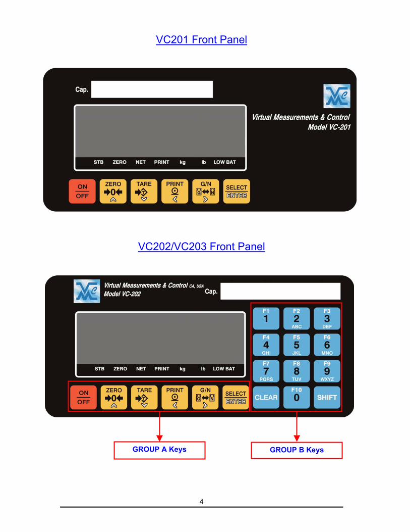
VC201 Front Panel
VC202/VC203 Front Panel
GROUP B KeysGROUP A Keys
5
Status Indicators
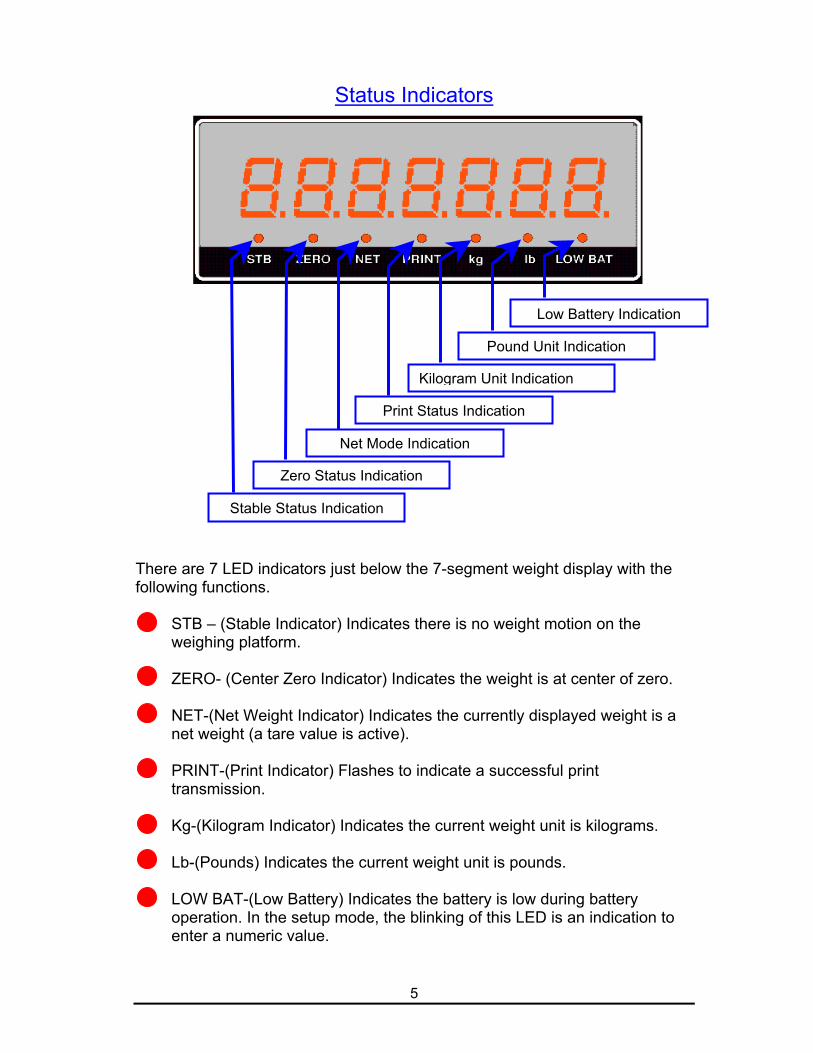
There are 7 LED indicators just below the 7-segment weight display with thefollowing functions.
STB – (Stable Indicator) Indicates there is no weight motion on theweighing platform.
ZERO- (Center Zero Indicator) Indicates the weight is at center of zero.
NET-(Net Weight Indicator) Indicates the currently displayed weight is anet weight (a tare value is active).
PRINT-(Print Indicator) Flashes to indicate a successful printtransmission.
Kg-(Kilogram Indicator) Indicates the current weight unit is kilograms.
Lb-(Pounds) Indicates the current weight unit is pounds.
LOW BAT-(Low Battery) Indicates the battery is low during batteryoperation. In the setup mode, the blinking of this LED is an indication toenter a numeric value.
Low Battery Indication
Pound Unit Indication
Kilogram Unit Indication
Print Status Indication
Net Mode Indication
Zero Status Indication
Stable Status Indication
6
Key Functions Group ‘A’
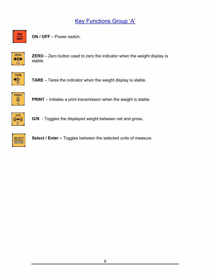
ON / OFF – Power switch.
ZERO – Zero button used to zero the indicator when the weight display isstable.
TARE – Tares the indicator when the weight display is stable.
PRINT – Initiates a print transmission when the weight is stable.
G/N - Toggles the displayed weight between net and gross.
Select / Enter – Toggles between the selected units of measure.
7
Optional Key Functions Group ‘B’
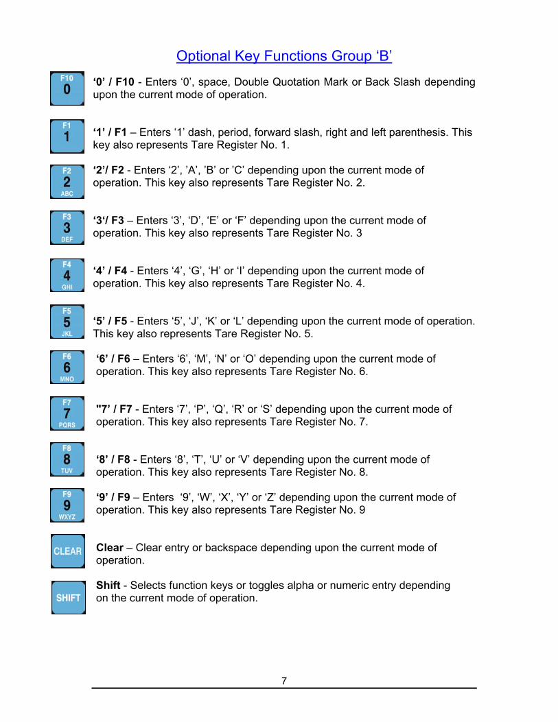
‘0’ / F10 - Enters ‘0’, space, Double Quotation Mark or Back Slash dependingupon the current mode of operation.
‘1’ / F1 – Enters ‘1’ dash, period, forward slash, right and left parenthesis. Thiskey also represents Tare Register No. 1.
‘2’/ F2 - Enters ‘2’, ’A’, ’B’ or ’C’ depending upon the current mode ofoperation. This key also represents Tare Register No. 2.
‘3‘/ F3 – Enters ‘3’, ‘D’, ‘E’ or ‘F’ depending upon the current mode ofoperation. This key also represents Tare Register No. 3
‘4’ / F4 - Enters ‘4’, ‘G’, ‘H’ or ‘I’ depending upon the current mode ofoperation. This key also represents Tare Register No. 4.
‘5’ / F5 - Enters ‘5’, ‘J’, ‘K’ or ‘L’ depending upon the current mode of operation.This key also represents Tare Register No. 5.
‘6’ / F6 – Enters ‘6’, ‘M’, ‘N’ or ‘O’ depending upon the current mode of operation. This key also represents Tare Register No. 6.
"7’ / F7 - Enters ‘7’, ‘P’, ‘Q’, ‘R’ or ‘S’ depending upon the current mode of operation. This key also represents Tare Register No. 7.
‘8’ / F8 - Enters ‘8’, ‘T’, ‘U’ or ‘V’ depending upon the current mode of operation. This key also represents Tare Register No. 8.
‘9’ / F9 – Enters ‘9’, ‘W’, ‘X’, ‘Y’ or ‘Z’ depending upon the current mode of operation. This key also represents Tare Register No. 9
Clear – Clear entry or backspace depending upon the current mode of operation.
Shift - Selects function keys or toggles alpha or numeric entry depending on the current mode of operation.
8
Operating Instructions
Power ON ZeroingUpon applying power the instrument will:
i) If the applied load is less than or equal to 2% of the calibration zero
point the instrument will establish zero and clear any tare values.
ii) If the applied load is greater than 2% of the calibration zero point the
instrument will display “- - - - - - -“. The load may be removed to
allow for automatic zeroing (above) or a manual zero may be
established by pressing the ‘Zero’ button. Note: If the instrument has
been configured to not allow for zeroing greater than 2% removing
the load will be necessary.
ZeroingTo zero the scale press the [Zero] button.
i) 2 % Zeroing
(1) This mode will allow pushbutton zero up to 2% of full scale
capacity. The available scale capacity will not be affected by the
zeroed amount.
ii) 100 % Zeroing
(1) This mode will allow pushbutton zero up to 100% of full scale
capacity. The available scale capacity will be reduced by the
zeroed amount.
Pushbutton Tare (If enabled)
Place the object to tare on the scale and press the [Tare] button.
The weight will be established as tare and the weight mode will
switch to net.
Tare by Numeric Key (VC202 & VC203, if enabled)
Key in the tare value using the numeric keys then press [Tare].In sealed applications this function is only permitted when the
gross weight is at zero.
9
Programming Recall Tare Values (VC202 & VC203, if enabled)
(1) The VC202 & VC203 can maintain up to 10 predefined Tare
values.
(2) To program a tare value press [Shift] and then [8]. The display
will prompt [T 0-END] and then [t no. 1]
(3) Key in the desired tare register number (1-10) and press [Enter].(4) The display will prompt [T XXX.XX]
(5) Enter the desired tare value.
(6) To Exit programming tare registers, enter ‘0’ at the tare register
prompt.
Recalling a Tare Value (VC202 & VC203, if enabled)
Enter the desired tare register (1-10) then press the
[Select/Enter] key. In sealed applications this function is only
available when the gross weight is at zero.
Preset Output Settings (VC202 & VC203, if enabled)
. Press [SHIFT] then press [ 9 ],
The display will prompt [S XXX.XX]. Key in the Start value for
Set point 1 and press [Enter],The display will prompt [E XXX.XX]. Key in the End value for
Set point 1 and press [Enter]Repeat the above sequence for Set point 2.
10
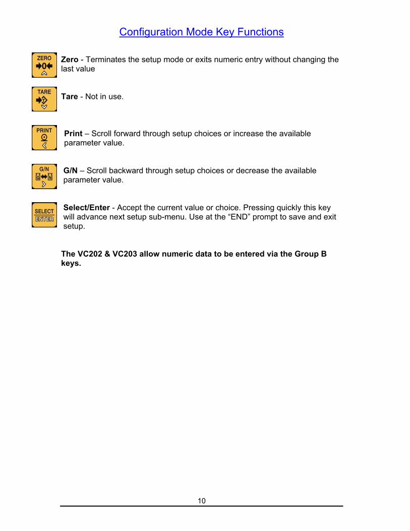
Configuration Mode Key Functions
Zero - Terminates the setup mode or exits numeric entry without changing thelast value
Tare - Not in use.
Print – Scroll forward through setup choices or increase the availableparameter value.
G/N – Scroll backward through setup choices or decrease the available parameter value.
Select/Enter - Accept the current value or choice. Pressing quickly this key will advance next setup sub-menu. Use at the “END” prompt to save and exit setup.
The VC202 & VC203 allow numeric data to be entered via the Group Bkeys.
11
Setup/Configuration Mode Access
There are two ways to access the Setup/Configuration Mode:
1) Using the Calibration Jumper (JP1)
i) Turn off the instrument and insert Jumper 1 (JP1).
ii) Turn the instrument on, the display will show the Audit Trail then
prompt for password entry [P 0].
iii) Enter the password “2001” and press the [Enter] key.
2) “Hot Key” entry if enabled (C1.2 is set to Enable.)
i) Press the [G/N] and [Enter] keys together while in normal operation
mode
ii) The display will show the Audit Trail then prompt for password entry
[P 0].
iii) Enter the setup/calibration password and press the [Enter] key.
Configuration/Calibration ModeCategory Selection:The setup mode is arranged into major categories and their individual
selections. Upon entering the setup mode the display will prompt ‘C1’
indicating category ‘1’. Using the ‘Print’ and ‘G/N’ keys scroll through the setup
categories until the desired category is displayed. When the desired category
is displayed press the ‘Enter’ key to begin setup. Pressing ‘Zero’ while in the
category menu will prompt ‘END’, pressing ‘Enter’ at this prompt exits the
setup menu.
Setup Selection:After entering the desired category use the ‘Print’ and ‘G/N’ keys to toggle
setup choices or alter setup values. Press ‘Enter’ to accept when the desired
value is displayed to save the value and advance to the next selection.
Note: Features requiring the Group B Function keys will not be availablewhen configuring the VC201
12
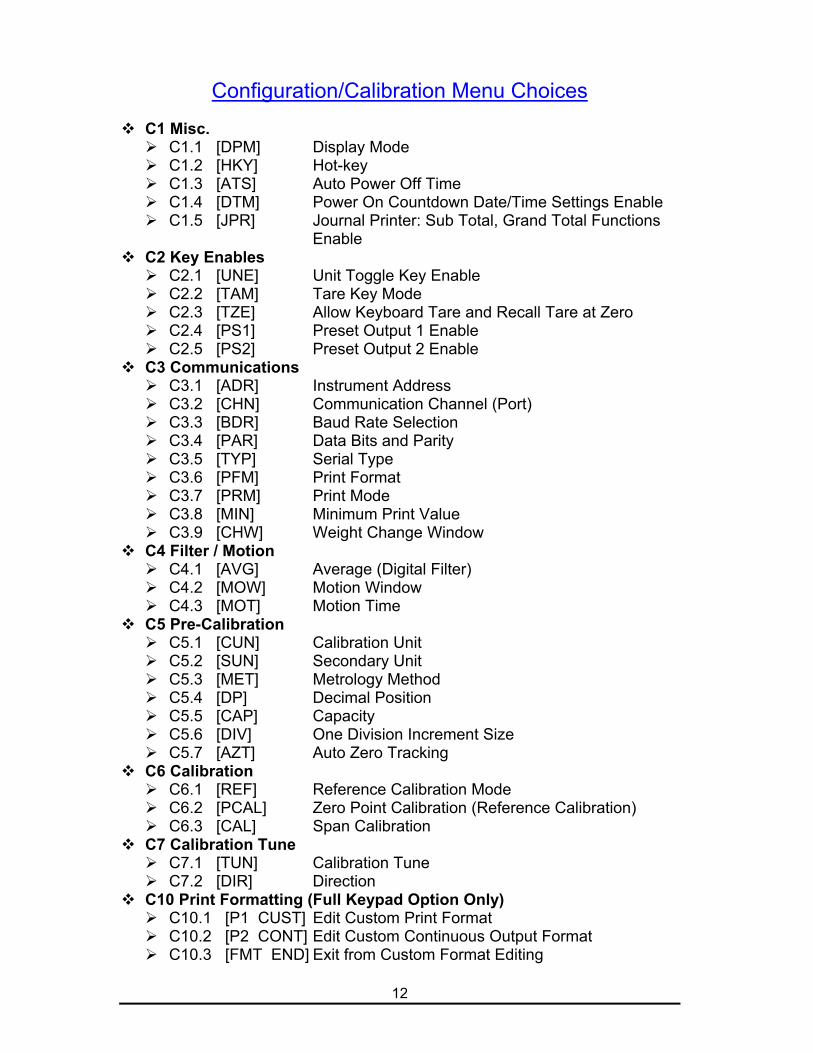
Configuration/Calibration Menu Choices
C1 Misc. C1.1 [DPM] Display Mode C1.2 [HKY] Hot-key C1.3 [ATS] Auto Power Off Time C1.4 [DTM] Power On Countdown Date/Time Settings Enable C1.5 [JPR] Journal Printer: Sub Total, Grand Total Functions
Enable C2 Key Enables
C2.1 [UNE] Unit Toggle Key Enable C2.2 [TAM] Tare Key Mode C2.3 [TZE] Allow Keyboard Tare and Recall Tare at Zero C2.4 [PS1] Preset Output 1 Enable C2.5 [PS2] Preset Output 2 Enable
C3 Communications C3.1 [ADR] Instrument Address C3.2 [CHN] Communication Channel (Port) C3.3 [BDR] Baud Rate Selection C3.4 [PAR] Data Bits and Parity C3.5 [TYP] Serial Type C3.6 [PFM] Print Format C3.7 [PRM] Print Mode C3.8 [MIN] Minimum Print Value C3.9 [CHW] Weight Change Window
C4 Filter / Motion C4.1 [AVG] Average (Digital Filter) C4.2 [MOW] Motion Window C4.3 [MOT] Motion Time
C5 Pre-Calibration C5.1 [CUN] Calibration Unit C5.2 [SUN] Secondary Unit C5.3 [MET] Metrology Method C5.4 [DP] Decimal Position C5.5 [CAP] Capacity C5.6 [DIV] One Division Increment Size C5.7 [AZT] Auto Zero Tracking
C6 Calibration C6.1 [REF] Reference Calibration Mode C6.2 [PCAL] Zero Point Calibration (Reference Calibration) C6.3 [CAL] Span Calibration
C7 Calibration Tune C7.1 [TUN] Calibration Tune C7.2 [DIR] Direction
C10 Print Formatting (Full Keypad Option Only) C10.1 [P1 CUST] Edit Custom Print Format C10.2 [P2 CONT] Edit Custom Continuous Output Format C10.3 [FMT END] Exit from Custom Format Editing
13
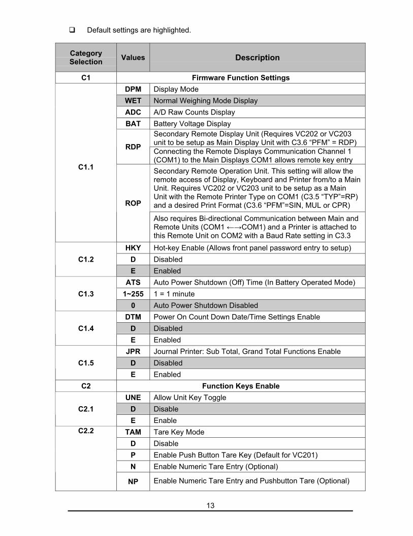
Default settings are highlighted.
CategorySelection Values Description
C1 Firmware Function SettingsDPM Display ModeWET Normal Weighing Mode DisplayADC A/D Raw Counts DisplayBAT Battery Voltage Display
Secondary Remote Display Unit (Requires VC202 or VC203unit to be setup as Main Display Unit with C3.6 “PFM” = RDP)RDP Connecting the Remote Displays Communication Channel 1(COM1) to the Main Displays COM1 allows remote key entrySecondary Remote Operation Unit. This setting will allow theremote access of Display, Keyboard and Printer from/to a MainUnit. Requires VC202 or VC203 unit to be setup as a MainUnit with the Remote Printer Type on COM1 (C3.5 “TYP”=RP)and a desired Print Format (C3.6 “PFM”=SIN, MUL or CPR)
C1.1
ROP
Also requires Bi-directional Communication between Main andRemote Units (COM1 ←→COM1) and a Printer is attached tothis Remote Unit on COM2 with a Baud Rate setting in C3.3
HKY Hot-key Enable (Allows front panel password entry to setup)D DisabledC1.2E Enabled
ATS Auto Power Shutdown (Off) Time (In Battery Operated Mode)1~255 1 = 1 minuteC1.3
0 Auto Power Shutdown DisabledDTM Power On Count Down Date/Time Settings Enable
D DisabledC1.4E Enabled
JPR Journal Printer: Sub Total, Grand Total Functions EnableD DisabledC1.5E Enabled
C2 Function Keys EnableUNE Allow Unit Key Toggle
D DisableC2.1E Enable
TAM Tare Key ModeD DisableP Enable Push Button Tare Key (Default for VC201)N Enable Numeric Tare Entry (Optional)
C2.2
NP Enable Numeric Tare Entry and Pushbutton Tare (Optional)
14
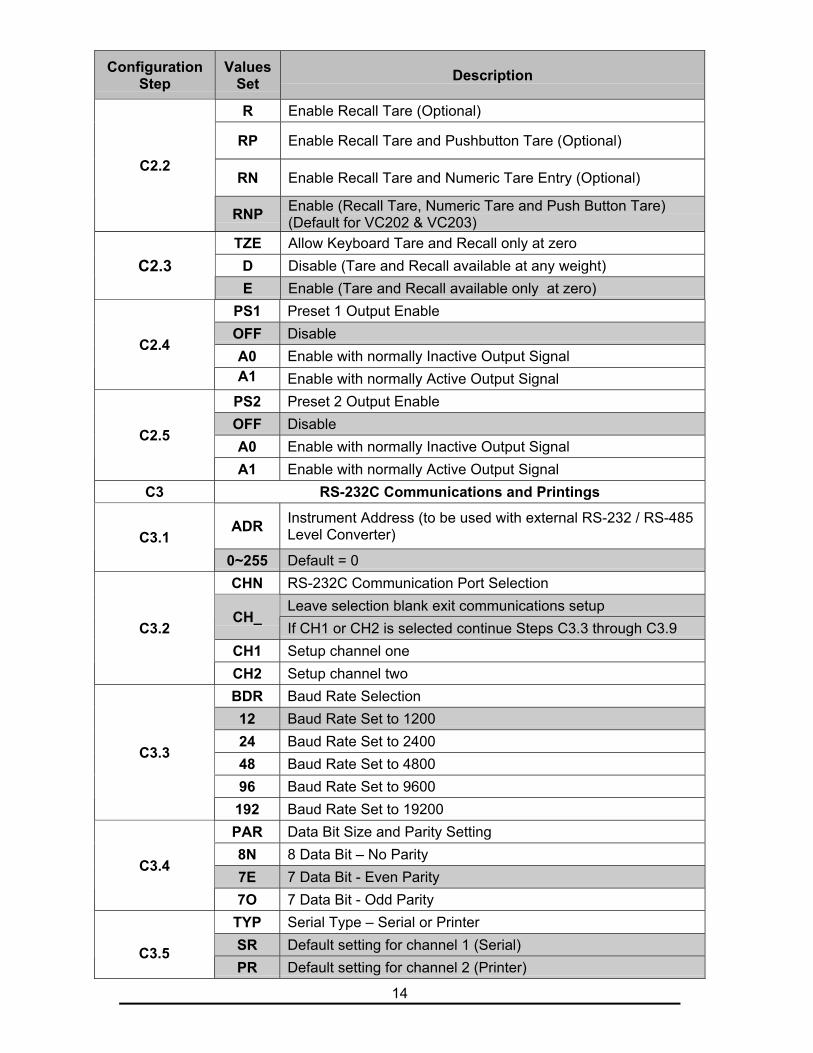
ConfigurationStep
ValuesSet Description
R Enable Recall Tare (Optional)
RP Enable Recall Tare and Pushbutton Tare (Optional)
RN Enable Recall Tare and Numeric Tare Entry (Optional)C2.2
RNP Enable (Recall Tare, Numeric Tare and Push Button Tare)(Default for VC202 & VC203)
TZE Allow Keyboard Tare and Recall only at zeroD Disable (Tare and Recall available at any weight)C2.3E Enable (Tare and Recall available only at zero)
PS1 Preset 1 Output EnableOFF DisableA0 Enable with normally Inactive Output Signal
C2.4
A1 Enable with normally Active Output SignalPS2 Preset 2 Output EnableOFF DisableA0 Enable with normally Inactive Output Signal
C2.5
A1 Enable with normally Active Output SignalC3 RS-232C Communications and Printings
ADR Instrument Address (to be used with external RS-232 / RS-485Level Converter)C3.1
0~255 Default = 0CHN RS-232C Communication Port Selection
Leave selection blank exit communications setupCH_
If CH1 or CH2 is selected continue Steps C3.3 through C3.9CH1 Setup channel one
C3.2
CH2 Setup channel twoBDR Baud Rate Selection12 Baud Rate Set to 120024 Baud Rate Set to 240048 Baud Rate Set to 480096 Baud Rate Set to 9600
C3.3
192 Baud Rate Set to 19200PAR Data Bit Size and Parity Setting8N 8 Data Bit – No Parity7E 7 Data Bit - Even Parity
C3.4
7O 7 Data Bit - Odd ParityTYP Serial Type – Serial or PrinterSR Default setting for channel 1 (Serial) C3.5PR Default setting for channel 2 (Printer)
15
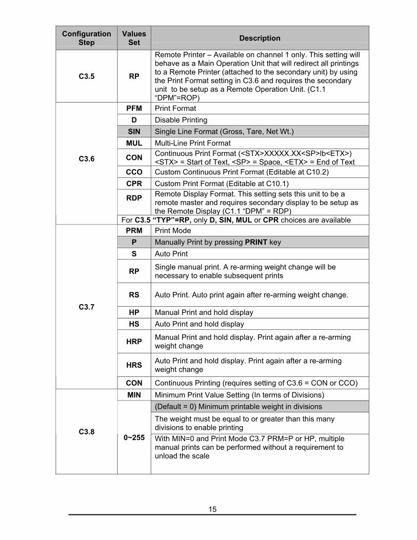
ConfigurationStep
ValuesSet Description
C3.5 RP
Remote Printer – Available on channel 1 only. This setting willbehave as a Main Operation Unit that will redirect all printingsto a Remote Printer (attached to the secondary unit) by usingthe Print Format setting in C3.6 and requires the secondaryunit to be setup as a Remote Operation Unit. (C1.1“DPM”=ROP)
PFM Print FormatD Disable Printing
SIN Single Line Format (Gross, Tare, Net Wt.)MUL Multi-Line Print Format
CON Continuous Print Format (<STX>XXXXX.XX<SP>lb<ETX>)<STX> = Start of Text, <SP> = Space, <ETX> = End of Text
CCO Custom Continuous Print Format (Editable at C10.2)CPR Custom Print Format (Editable at C10.1)
RDP Remote Display Format. This setting sets this unit to be aremote master and requires secondary display to be setup asthe Remote Display (C1.1 “DPM” = RDP)
C3.6
For C3.5 “TYP”=RP, only D, SIN, MUL or CPR choices are availablePRM Print Mode
P Manually Print by pressing PRINT keyS Auto Print
RP Single manual print. A re-arming weight change will benecessary to enable subsequent prints
RS Auto Print. Auto print again after re-arming weight change.
HP Manual Print and hold displayHS Auto Print and hold display
HRP Manual Print and hold display. Print again after a re-armingweight change
HRS Auto Print and hold display. Print again after a re-armingweight change
C3.7
CON Continuous Printing (requires setting of C3.6 = CON or CCO)MIN Minimum Print Value Setting (In terms of Divisions)
(Default = 0) Minimum printable weight in divisionsThe weight must be equal to or greater than this manydivisions to enable printingC3.8
0~255 With MIN=0 and Print Mode C3.7 PRM=P or HP, multiplemanual prints can be performed without a requirement tounload the scale
16
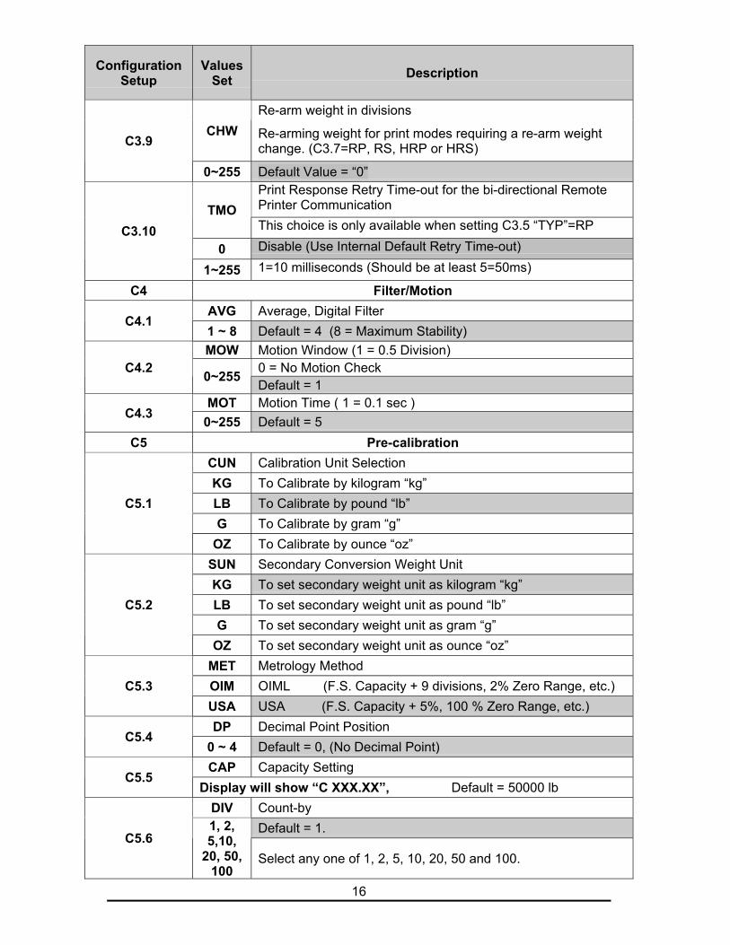
ConfigurationSetup
ValuesSet Description
Re-arm weight in divisionsCHW Re-arming weight for print modes requiring a re-arm weight
change. (C3.7=RP, RS, HRP or HRS)C3.9
0~255 Default Value = “0”Print Response Retry Time-out for the bi-directional RemotePrinter CommunicationTMOThis choice is only available when setting C3.5 “TYP”=RP
0 Disable (Use Internal Default Retry Time-out)C3.10
1~255 1=10 milliseconds (Should be at least 5=50ms)
C4 Filter/MotionAVG Average, Digital Filter
C4.11 ~ 8 Default = 4 (8 = Maximum Stability)MOW Motion Window (1 = 0.5 Division)
0 = No Motion CheckC4.2 0~255Default = 1
MOT Motion Time ( 1 = 0.1 sec )C4.3 0~255 Default = 5C5 Pre-calibration
CUN Calibration Unit SelectionKG To Calibrate by kilogram “kg”LB To Calibrate by pound “lb”G To Calibrate by gram “g”
C5.1
OZ To Calibrate by ounce “oz”SUN Secondary Conversion Weight UnitKG To set secondary weight unit as kilogram “kg”LB To set secondary weight unit as pound “lb”G To set secondary weight unit as gram “g”
C5.2
OZ To set secondary weight unit as ounce “oz”MET Metrology MethodOIM OIML (F.S. Capacity + 9 divisions, 2% Zero Range, etc.)C5.3USA USA (F.S. Capacity + 5%, 100 % Zero Range, etc.)DP Decimal Point Position
C5.40 ~ 4 Default = 0, (No Decimal Point)CAP Capacity Setting
C5.5Display will show “C XXX.XX”, Default = 50000 lb
DIV Count-byDefault = 1.
C5.61, 2,5,10,
20, 50,100
Select any one of 1, 2, 5, 10, 20, 50 and 100.
17
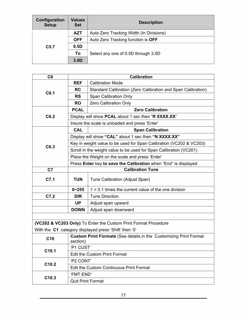
ConfigurationSetup
ValuesSet Description
AZT Auto Zero Tracking Width (In Divisions)OFF Auto Zero Tracking function is OFF0.5DTo
C5.7
3.0DSelect any one of 0.5D through 3.0D
C6 CalibrationREF Calibration ModeRC Standard Calibration (Zero Calibration and Span Calibration)RS Span Calibration Only
C6.1
RO Zero Calibration OnlyPCAL Zero Calibration
Display will show PCAL about 1 sec then “R XXXX.XX”C6.2Insure the scale is unloaded and press ‘Enter’
CAL Span CalibrationDisplay will show “CAL” about 1 sec then “N XXXX.XX”Key in weight value to be used for Span Calibration (VC202 & VC203)Scroll in the weight value to be used for Span Calibration (VC201)Place the Weight on the scale and press ‘Enter’
C6.3
Press Enter key to save the Calibration when “End” is displayedC7 Calibration Tune
C7.1 TUN Tune Calibration (Adjust Span)
0~255 1 = 0.1 times the current value of the one divisionC7.2 DIR Tune Direction
UP Adjust span upwardDOWN Adjust span downward
(VC202 & VC203 Only) To Enter the Custom Print Format ProcedureWith the C1 category displayed press ‘Shift’ then ‘0’
C10 Custom Print Formats (See details in the Customizing Print Formatsection)‘P1 CUST’
C10.1Edit the Custom Print Format‘P2 CONT’
C10.2Edit the Custom Continuous Print Format‘FMT END’
C10.3Quit Print Format
18
Calibration Audit Trail
The audit trail consists of two event counters, one for the adjustment(calibration) parameters (audit trail 1) and one for configuration parameters(audit trail 2). The range will be (000 to 999) for each counter.
To view the audit counters press the ‘G/N’ and ‘Enter’ keys at the same timewhile the instrument is in the normal weighing mode. The audit trail will bedisplayed as long as the keys are held.
If the calibration jumper is installed the audit trail will be displayed momentarilybefore the password prompt.
The audit trail format will be:AXXX.YYY where:XXX is audit trail 1 and YYY is audit trail 2.
Audit trail one will increment when changes are made to:Pre-calibration dataCalibrationCalibration Tune
Audit trail two will increment when changes are made to:Filter settingsPrint related settings C3.6-C3.9,Print FormatWeight related operation keys such as Tare mode
19
Input/Output Connections
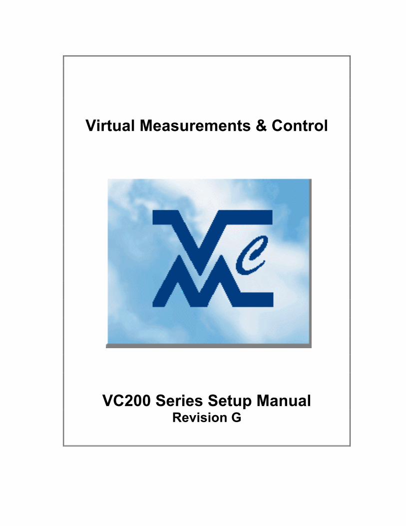
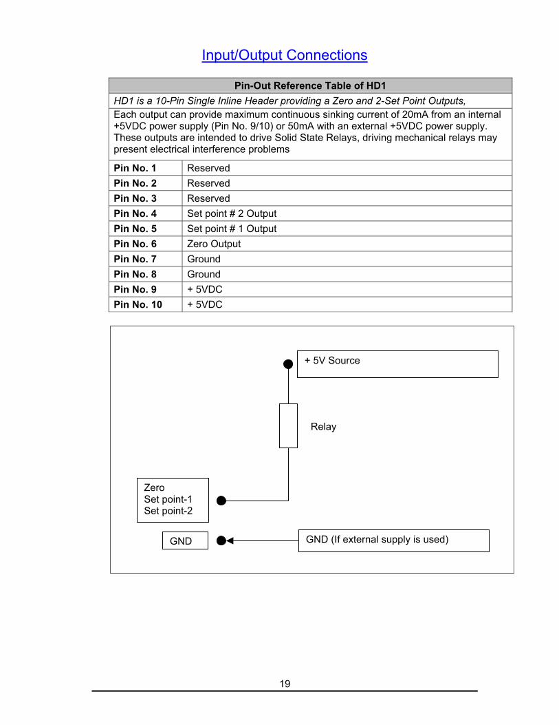
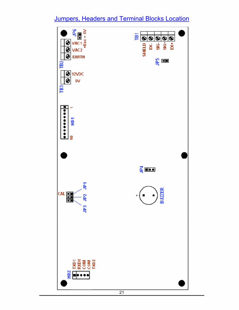
Pin-Out Reference Table of HD1HD1 is a 10-Pin Single Inline Header providing a Zero and 2-Set Point Outputs,Each output can provide maximum continuous sinking current of 20mA from an internal+5VDC power supply (Pin No. 9/10) or 50mA with an external +5VDC power supply.These outputs are intended to drive Solid State Relays, driving mechanical relays maypresent electrical interference problems
Pin No. 1 ReservedPin No. 2 ReservedPin No. 3 ReservedPin No. 4 Set point # 2 OutputPin No. 5 Set point # 1 OutputPin No. 6 Zero OutputPin No. 7 GroundPin No. 8 GroundPin No. 9 + 5VDCPin No. 10 + 5VDC
Relay
+ 5V Source
ZeroSet point-1Set point-2
GND GND (If external supply is used)
20
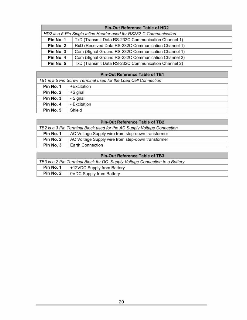
Pin-Out Reference Table of HD2HD2 is a 5-Pin Single Inline Header used for RS232-C Communication
Pin No. 1 TxD (Transmit Data RS-232C Communication Channel 1)Pin No. 2 RxD (Received Data RS-232C Communication Channel 1)Pin No. 3 Com (Signal Ground RS-232C Communication Channel 1)Pin No. 4 Com (Signal Ground RS-232C Communication Channel 2)Pin No. 5 TxD (Transmit Data RS-232C Communication Channel 2)
Pin-Out Reference Table of TB1TB1 is a 5 Pin Screw Terminal used for the Load Cell Connection
Pin No. 1 +ExcitationPin No. 2 +SignalPin No. 3 - SignalPin No. 4 - ExcitationPin No. 5 Shield
Pin-Out Reference Table of TB2TB2 is a 3 Pin Terminal Block used for the AC Supply Voltage Connection
Pin No. 1 AC Voltage Supply wire from step-down transformerPin No. 2 AC Voltage Supply wire from step-down transformerPin No. 3 Earth Connection
Pin-Out Reference Table of TB3TB3 is a 2 Pin Terminal Block for DC Supply Voltage Connection to a Battery
Pin No. 1 +12VDC Supply from BatteryPin No. 2 0VDC Supply from Battery
21
Jumpers, Headers and Terminal Blocks Location
22
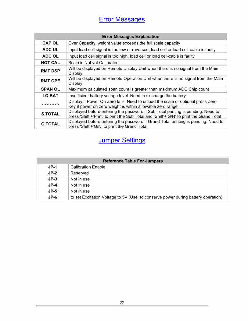
Error Messages
Error Messages ExplanationCAP OL Over Capacity, weight value exceeds the full scale capacityADC UL Input load cell signal is too low or reversed, load cell or load cell-cable is faultyADC OL Input load cell signal is too high, load cell or load cell-cable is faulty
NOT CAL Scale is Not yet Calibrated
RMT DSP Will be displayed on Remote Display Unit when there is no signal from the MainDisplay
RMT OPE Will be displayed on Remote Operation Unit when there is no signal from the MainDisplay
SPAN OL Maximum calculated span count is greater than maximum ADC Chip countLO BAT Insufficient battery voltage level. Need to re-charge the battery
- - - - - - - Display if Power On Zero fails. Need to unload the scale or optional press ZeroKey if power on zero weight is within allowable zero range
S.TOTAL Displayed before entering the password if Sub Total printing is pending. Need topress ‘Shift’+’Print’ to print the Sub Total and ‘Shift’+’G/N’ to print the Grand Total
G.TOTAL Displayed before entering the password if Grand Total printing is pending. Need topress ‘Shift’+’G/N’ to print the Grand Total
Jumper Settings
Reference Table For JumpersJP-1 Calibration EnableJP-2 ReservedJP-3 Not in useJP-4 Not in useJP-5 Not in useJP-6 to set Excitation Voltage to 5V (Use to conserve power during battery operation)
23
Customizing Print Format (Optional)Press [G/N] key and [Select/Enter] key together, Audit Trail will be displayed,when released the display will show [P 0] and the 7th LED will flash, whichmeans you need to enter the numeric value password to access the setup mode.
Key in the password [2] [0] [0] [1] and press [Enter], the display will show [C1 ]Press [Shift] then [0], [PRT FMT] will be displayed, then [P1 CUST] will bedisplayed.Here you can use the [PRINT] key or [G/N] key to browse the following three menus,(1) [P1 CUST] For Custom Print Formatting.(2) [P2 CONT] For Custom Formatting for Continuous Output.(3) [FMT END] to end the Custom Formatting and return to normal weighing mode.select the menu by pressing the Enter key and continue the setting.
The numeric characters (0, 1, … , 9), all alphabets (A, B, … , Z) and some othercharacters are already assigned to the Group-B keys (Ref: Key Explanation page asdescribe earlier) so these characters can be keyed in directly from Group-B keys.(Example: for “1” press [1] key,
for “A” press [Shift] then press [2] key,for “B” press [Shift] then press [2] and press [Shift] key.To confirm character entry, press [Enter] key after selecting the input
character).
There will be a blinking LED just below one of the 7-segment display digitswhich shows the active digit position or character insertion position.
The characters or text to be printed out should be placed inside the doublequotation marks.
(e.g. “FlexWeigh” will print out as FlexWeigh )
For Control characters or some other characters which cannot be used by thefront panel keys are to be keyed in by using the following format:
“\xxx” (where: xxx is the ASCII code or extended ASCII code (0~255) in decimal value of the character code to be printed)
Following Command Codes are provided:(1) “\R” = Carriage Return(2) “\N” = Line Feed
(3) “\E” = End of line (CR+LF) (e.g. “\E” = “\R\N” will be printed)(4) “\Lx” = “x” Line Feeds (e.g. “\L3” = “\N\N\N” = 3 Line Feeds will be printed)(5) “\Sx” = “x” Spaces (e.g. “\S4” = 4 spaces will be printed)(6) “\CX.Y” = Repeat printing a character X for a total of Y characters, X can be
“\xxx” form (e.g. “\C=.16” = Prints “=” for 16 characters or “\C\42.16 = Prints “*”for 16 characters)
Weight Format Command (WX.Y)X = Weight Type (0 = Net, 1 = Gross, 2 = Tare)Y = Field Width (Includes “.” if any)
Weight Unit Command (U)Appends the current unit of measurement to the printed weight and optional tareentry flag.(1) “^kg^^^” For Pushbutton Tare, Gross or Net Weight. (kg = current unit, ^= space)(2) “^kg(K)” For Keyboard Tare or Recall Tare Weight.
24
Delay Command (DX)Delay after print which is normally placed after CR/LF, where X = Delay Time
(1 = 0.1 sec).
Example: W1.8U = Print the gross weight right justified with a field width of 8followed by the current units: e.g. “ 3456.78 kg ”
To Print the current editing print format press [Tare] key then select [Print].To Erase the current editing print format press [Tare] key then select [Erase].
25
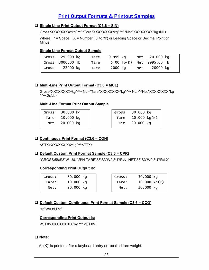
Print Output Formats & Printout Samples
Single Line Print Output Format (C3.6 = SIN)Gross^XXXXXXXX^kg^^^^^Tare^XXXXXXXX^kg^^^^^Net^XXXXXXXX^kg<NL>
Where: ^ = Space, X = Number (‘0’ to ‘9’) or Leading Space or Decimal Point or Minus
Single Line Format Output Sample
Multi-Line Print Output Format (C3.6 = MUL)Gross^XXXXXXXX^kg^^^<NL>^Tare^XXXXXXXX^kg^^^<NL>^^Net^XXXXXXXX^kg
^^^<2xNL>
Multi-Line Format Print Output Sample
Continuous Print Format (C3.6 = CON)<STX>XXXXXX.XX^kg^^^<ETX>
Default Custom Print Format Sample (C3.6 = CPR)“GROSS\58\S3”W1.8U”\R\N TARE\58\S3”W2.8U”\R\N NET\58\S3”W0.8U”\R\L2”
Corresponding Print Output is:
Default Custom Continuous Print Format Sample (C3.6 = CCO)“\2”W0.8U”\3”
Corresponding Print Output is:<STX>XXXXXX.XX^kg^^^<ETX>
Note:
A ‘(K)’ is printed after a keyboard entry or recalled tare weight.
Gross 29.999 kg Tare 9.999 kg Net 20.000 kg
Gross 3000.00 lb Tare 5.00 lb(K) Net 2995.00 lb
Gross 22000 kg Tare 2000 kg Net 20000 kg
Gross 30.000 kg
Tare 10.000 kg
Net 20.000 kg
Gross: 30.000 kg
Tare: 10.000 kg
Net: 20.000 kg
Gross 30.000 kg
Tare 10.000 kg(K)
Net 20.000 kg
Gross: 30.000 kg
Tare: 10.000 kg(K)
Net: 20.000 kg
26
Journal Print Format & Printout SampleJournal Print Format is enabled by the settings: 1) Custom Print Format Type (C3.6“PFM” = CPR) with the proper Journal Print Format in C10.1 as will be describedbelow, 2) Date/Time Setup Enable (C1.4 “DTM” = E) and 3) Journal Print FeatureEnable (C1.5 “JPR” = E) .Following commands are specially provided for Journal Printer Print Formats:
Journal Print Format Commands (FX)Where X = Format No. 1 to 5.Each of the following command defines the format header or a start position of
print format.F1 = Start of Main Title FormatF2 = Start of Sub Title FormatF3 = Start of Batch Weighing FormatF4 = Start of Sub Total FormatF5 = Start of Grand Total FormatNote: At the end of each format, “CR/LF” pair will be printed, except at the end of F5.
Code and Number Format Commands (NX)Where X = Format No. 1 to 4.Each of the following command represents the Code or Numeric Data to be printed.N1 = Product Code (10 Alpha-Numeric Characters)N2 = Consecutive No. (5 Numeric Characters)N3 = Sub Total Counts (5 Numeric Characters)N4 = Grand Total Counts (5 Numeric Characters)
Weight and Unit Format Commands (WX.Y.U)X = Weight Type (0 = Net, 1 = Gross, 2 = Tare,
3 = Sub Total Weight, 4 = Grand Total Weight).Y = Field Width (Includes “.” if any)U = Appends the current unit of measurement to the weight and optional tare entryflag.
(1) U = 0: Not print current unit of measurement. (Same as W.X.Y)(2) U = 1: Appends the current unit of measurement (“^kg”) to the printed weight.(3) U = 2: Appends as described in (2) but with 3 additional characters of tare
entry flag: (a) “^^^” For Pushbutton Tare, Gross or Net Weight (^ = Space). (b) “(K)” For Keyboard Tare or Recall Tare Weight.
Example: Following will print the net weight right justified with a field width of8 and will finally print a different type of optional current unit of measurementdescription: W0.8.0 = without current unit: e.g. “ 3456.78” (same as W0.8).
W0.8.1 = 1 space and 2 characters of current unit: e.g. “ 3456.78 kg”.W0.8.2 = 1 space and 2 characters of current unit with 3 extra spaces of tare
flag. e.g. “ 3456.78 kg ” (same as W.0.8U).
27
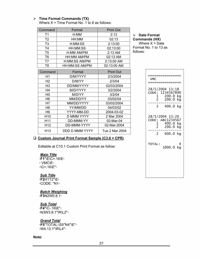
Time Format Commands (TX)Where X = Time Format No. 1 to 8 as follows:
Date FormatCommands (HX)
Where X = DateFormat No. 1 to 13 asfollows:
Custom Journal Print Format Sample (C3.6 = CPR)
Editable at C10.1 Custom Print Format as follow:
Main Title ◦F1"\E\C=.16\E◦ ◦ VMC\E◦ ◦\C=.16\E"◦
Sub Title ◦F2H1T2"\E◦ ◦CODE: "N1◦
Batch Weighing ◦F3N2W0.8.1◦
Sub Total ◦F4"\C-.16\E"◦ ◦N3W3.8.1"\R\L2"◦
Grand Total ◦F5"TOTAL:\S5"N4"\E"◦ ◦W4.13.1"\R\L4"◦
Note:
Command Format Print OutT1 H:MM 2:13T2 HH:MM 02:13T3 H:MM:SS 2:13:00T4 HH:MM:SS 02:13:00T5 H:MM AM/PM 2:13 AMT6 HH:MM AM/PM 02:13 AMT7 H:MM:SS AM/PM 2:13:00 AMT8 HH:MM:SS AM/PM 02:13:00 AM
Command Format Print OutH1 D/M/YYYY 2/3/2004H2 D/M/YY 2/3/04H3 DD/MM/YYYY 02/03/2004H4 M/D/YYYY 3/2/2004H5 M/D/YY 3/2/04H6 MM/DD/YY 03/02/04H7 MM/DD/YYYY 03/02/2004H8 YY/MM/DD 04/03/02H9 YYYY-MM-DD 2004-03-02
H10 D MMM YYYY 2 Mar 2004H11 DD-MMM-YY 02-Mar-04H12 DD-MMM-YYYY 02-Mar-2004H13 DDD D MMM YYYY Tue 2 Mar 2004
================ VMC================
28/5/2004 13:18CODE: 1234567890 1 200.0 kg 2 200.0 kg---------------- 2 400.0 kg
28/5/2004 13:20CODE: ABC1234567 1 400.0 kg 2 200.0 kg---------------- 2 600.0 kg
TOTAL: 4 1000.0 kg

28
The actual custom print format that will be shown inside the “C10.1” edit bufferis the continuous extraction of any characters located between the twodelimited symbols “◦” of the above multi-line print format sample.
To quickly jump to the start of each format (F1 to F5) during editing the customprint format, press [Shift] key then press [>] or [<] key to jump to the next orprevious journal print format position respectively.
The right figure shows the print output of the above custom journal print formatsample.
29
Journal Print Format Key Operation
Following procedures are only available when the Custom Print Format contains thespecific Journal Print Format as described in the previous section. It requires 3 mainprinting steps to complete the Operation, i.e. (1) Batch Weighing, (2) Sub Total and(3) Grand Total as follows:
How to print the Batch Weighing:1) Before starting the first weighing of each new batch, enter the Product Code (10
alpha-numeric characters) by using the Function Key [F1] (Press [Shift] thenpress [1]).Note: Enter the Product Code in the same way as editing the Custom Print Format in
C10.1. To Delete all characters of Product Code at once, press [Shift] then press
[Clear]. The Function Key [F1] is automatically enabled when the Sub Title Format
(F2) contains the Product Code (N1) command.2) Perform a consecutive batch weighing as usual, i.e. when the weight becomes
stable, either Manually Print or an Auto Print should be issued depending on thesetting in C3.7 “PRM”. Following conditional print formats will be printed:(i) Main Title Print Format (F1):
Printed only once at the start of the First Batch Weighing. Normally theCompany Name is printed here.
(ii) Sub Title Print Format (F2):Printed only once at the start of each New Batch Weighing. NormallyDate/Time and Product Code is printed here.
(iii) Batch Weighing Format (F3):Once the above two conditional formats are printed, each weighing in a batchwill be printed consecutively. Normally Consecutive No. and Net Weight withcurrent selected unit are printed here. After printing, the following data will beupdated:
a) Consecutive No. (N2) will be increased by one.b) Sub Total Count (N3) will be increased by one.c) The Printed (Net) Weight (W0) will be accumulated to the Sub Total
Weight (W3)3) Continue the next consecutive weighing as described in step (2.iii) if required.4) For the last Batch Weighing, issue the Sub Total Data Print as shown below.
How to print the Sub Total:After printing the last weighing of each batch, issue the Sub Total Data Print asfollows:1) Press [Shift] then press [Print].2) The Sub Total Print Format (F4) Data will be printed. Normally line separator,
Sub Total Data e.g. Accumulated Counts (N3) and Accumulated Weight (W3) willbe printed here.
3) After printing the Sub Total Data, the following will be reset:a) Consecutive No. (N2) will be reset to one.b) Sub Total Count (N3) will be cleared to zeroc) Sub Total Weight (W3) will be cleared to zero.
4) Continue the next batch with the above How to print the Batch Weighing ifrequired.
5) For the last batch Sub Total printing, issue the Grand Total Data Print as shownbelow.
30
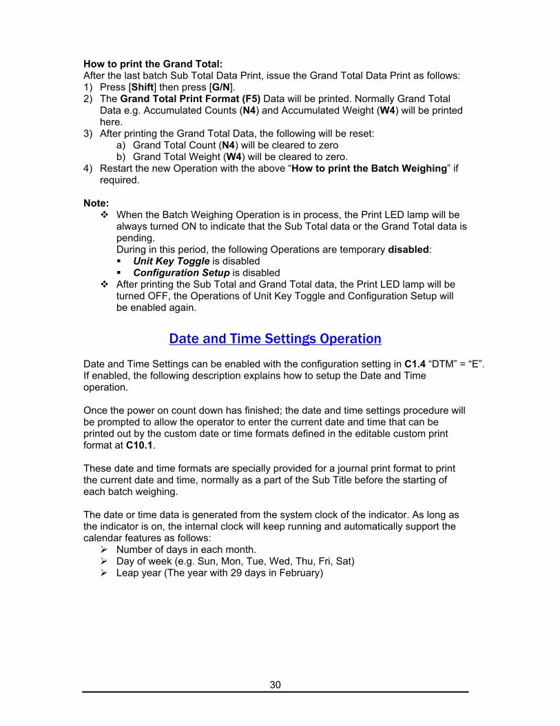
How to print the Grand Total:After the last batch Sub Total Data Print, issue the Grand Total Data Print as follows:1) Press [Shift] then press [G/N].2) The Grand Total Print Format (F5) Data will be printed. Normally Grand Total
Data e.g. Accumulated Counts (N4) and Accumulated Weight (W4) will be printedhere.
3) After printing the Grand Total Data, the following will be reset:a) Grand Total Count (N4) will be cleared to zerob) Grand Total Weight (W4) will be cleared to zero.
4) Restart the new Operation with the above “How to print the Batch Weighing” ifrequired.
Note: When the Batch Weighing Operation is in process, the Print LED lamp will be
always turned ON to indicate that the Sub Total data or the Grand Total data ispending.During in this period, the following Operations are temporary disabled: Unit Key Toggle is disabled Configuration Setup is disabled
After printing the Sub Total and Grand Total data, the Print LED lamp will beturned OFF, the Operations of Unit Key Toggle and Configuration Setup willbe enabled again.
Date and Time Settings Operation
Date and Time Settings can be enabled with the configuration setting in C1.4 “DTM” = “E”.If enabled, the following description explains how to setup the Date and Timeoperation.
Once the power on count down has finished; the date and time settings procedure willbe prompted to allow the operator to enter the current date and time that can beprinted out by the custom date or time formats defined in the editable custom printformat at C10.1.
These date and time formats are specially provided for a journal print format to printthe current date and time, normally as a part of the Sub Title before the starting ofeach batch weighing.
The date or time data is generated from the system clock of the indicator. As long asthe indicator is on, the internal clock will keep running and automatically support thecalendar features as follows:
Number of days in each month. Day of week (e.g. Sun, Mon, Tue, Wed, Thu, Fri, Sat) Leap year (The year with 29 days in February)
31
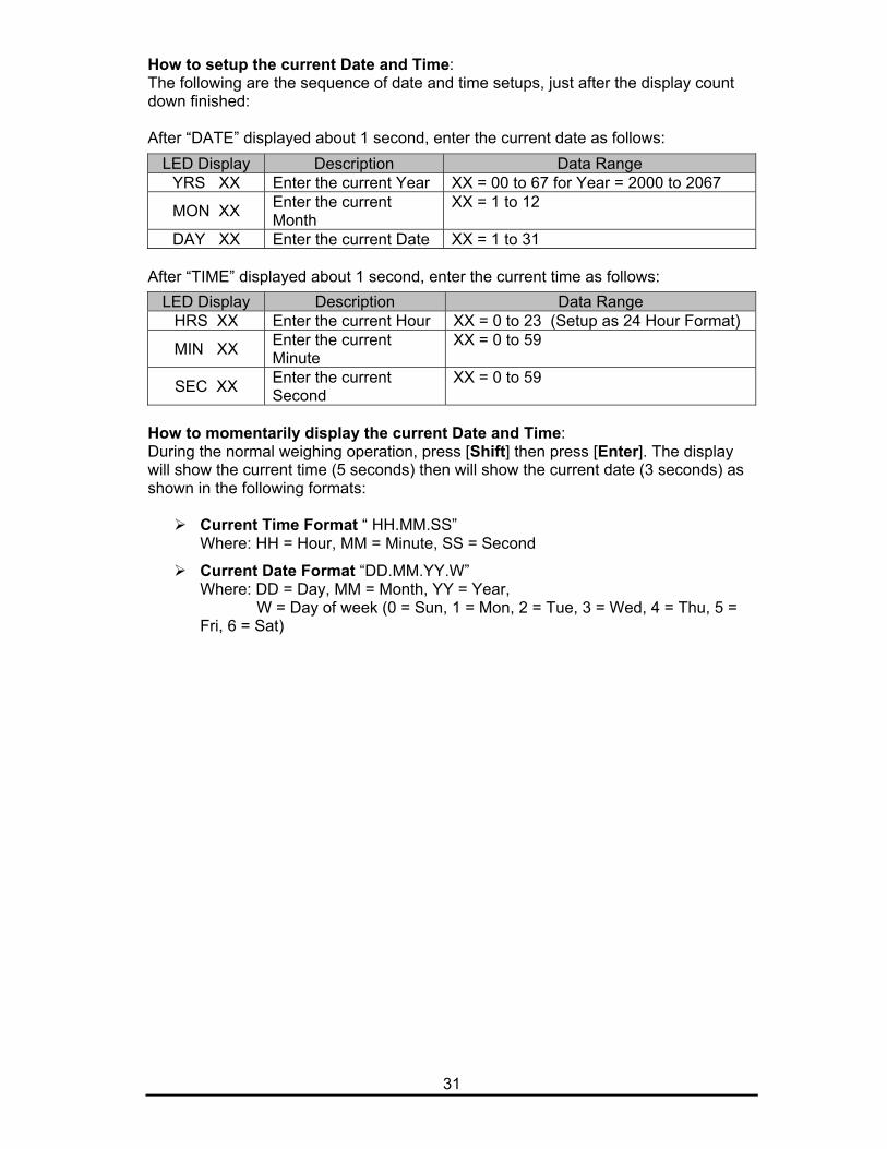
How to setup the current Date and Time:The following are the sequence of date and time setups, just after the display countdown finished:
After “DATE” displayed about 1 second, enter the current date as follows:
After “TIME” displayed about 1 second, enter the current time as follows:
How to momentarily display the current Date and Time:During the normal weighing operation, press [Shift] then press [Enter]. The displaywill show the current time (5 seconds) then will show the current date (3 seconds) asshown in the following formats:
Current Time Format “ HH.MM.SS”Where: HH = Hour, MM = Minute, SS = Second
Current Date Format “DD.MM.YY.W”Where: DD = Day, MM = Month, YY = Year,
W = Day of week (0 = Sun, 1 = Mon, 2 = Tue, 3 = Wed, 4 = Thu, 5 =Fri, 6 = Sat)
LED Display Description Data RangeYRS XX Enter the current Year XX = 00 to 67 for Year = 2000 to 2067
MON XX Enter the currentMonth
XX = 1 to 12
DAY XX Enter the current Date XX = 1 to 31
LED Display Description Data RangeHRS XX Enter the current Hour XX = 0 to 23 (Setup as 24 Hour Format)
MIN XX Enter the currentMinute
XX = 0 to 59
SEC XX Enter the currentSecond
XX = 0 to 59
32
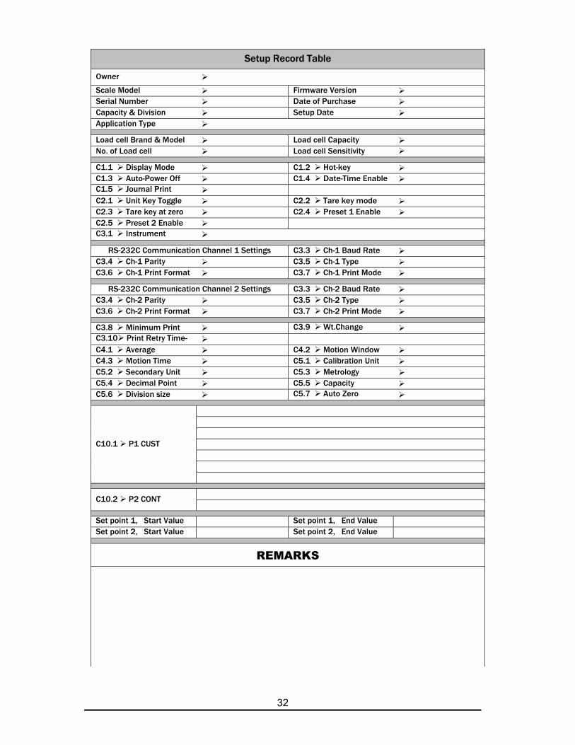
Setup Record Table
Owner
Scale Model Firmware VersionSerial Number Date of PurchaseCapacity & Division Setup DateApplication Type
Load cell Brand & Model Load cell CapacityNo. of Load cell Load cell Sensitivity
C1.1 Display Mode C1.2 Hot-keyC1.3 Auto-Power Off C1.4 Date-Time EnableC1.5 Journal PrintC2.1 Unit Key Toggle C2.2 Tare key modeC2.3 Tare key at zero C2.4 Preset 1 EnableC2.5 Preset 2 EnableC3.1 Instrument
RS-232C Communication Channel 1 Settings C3.3 Ch-1 Baud RateC3.4 Ch-1 Parity C3.5 Ch-1 TypeC3.6 Ch-1 Print Format C3.7 Ch-1 Print Mode
RS-232C Communication Channel 2 Settings C3.3 Ch-2 Baud RateC3.4 Ch-2 Parity C3.5 Ch-2 TypeC3.6 Ch-2 Print Format C3.7 Ch-2 Print Mode
C3.8 Minimum Print C3.9 Wt.ChangeC3.10 Print Retry Time-C4.1 Average C4.2 Motion WindowC4.3 Motion Time C5.1 Calibration UnitC5.2 Secondary Unit C5.3 MetrologyC5.4 Decimal Point C5.5 CapacityC5.6 Division size C5.7 Auto Zero
C10.1 P1 CUST
C10.2 P2 CONT
Set point 1, Start Value Set point 1, End ValueSet point 2, Start Value Set point 2, End Value
REMARKS
33
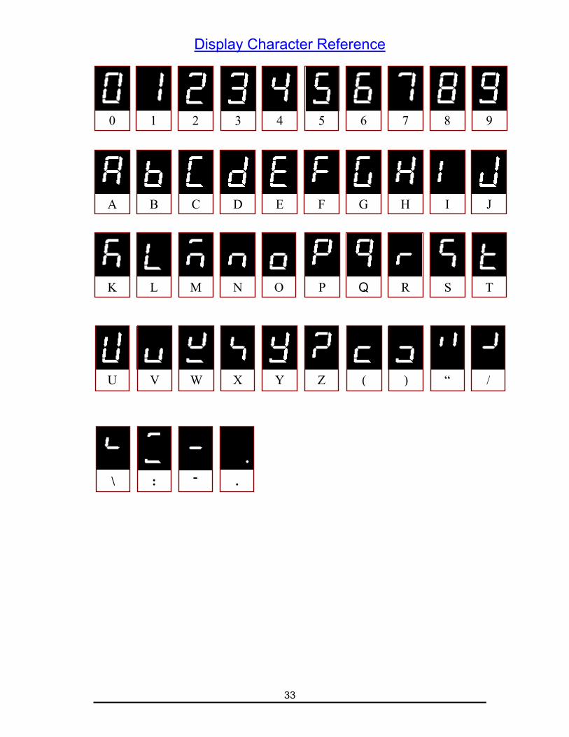
Display Character Reference
0 1 2 3 4 5 6 7 8 9
A B C ED F G H I J
K L M N O P Q R S T
U V W X Y Z ( ) “ /
\ : - .
34
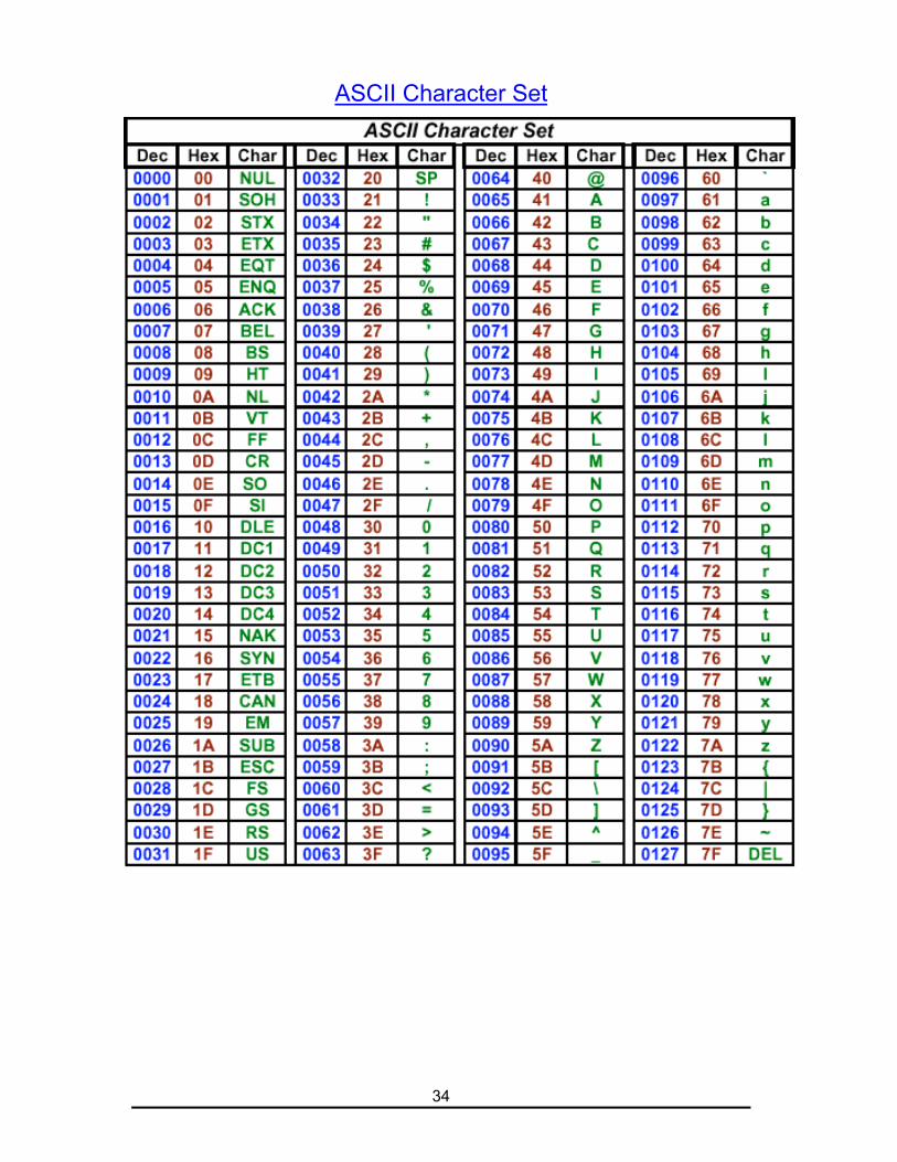
ASCII Character Set

35
Password
The calibration/configuration password is:
2001