Embed Size (px)
Citation preview
S5200F-ON SeriesSetup Guide

Notes, cautions, and warnings
NOTE: A NOTE indicates important information that helps you make better use of your product.
CAUTION: A CAUTION indicates either potential damage to hardware or loss of data and tells you how to avoid the problem.
WARNING: A WARNING indicates a potential for property damage, personal injury, or death.
Copyright © 2018 Dell Inc. or its subsidiaries. All rights reserved. Dell, EMC, and other trademarks are trademarks of Dell Inc. or its subsidiaries. Other trademarks may be trademarks of their respective owners.
2018 - 11
Rev. A01
Contents
1 About this guide..............................................................................5Regulatory................................................................................................. 5Related documents.................................................................................. 6Information symbols.................................................................................6
2 Site preparations............................................................................ 7Site selection............................................................................................. 7Cabinet placement................................................................................... 8Rack mounting..........................................................................................8Switch ground...........................................................................................8Fans and airflow....................................................................................... 9Power.........................................................................................................9Storing components............................................................................... 10
3 S5200F-ON Series switch Installation........................................... 11Unpack..................................................................................................... 12Ground cable........................................................................................... 13Rack or cabinet installation.................................................................... 13
Rack mount safety considerations..................................................14One-half U front-rack installation......................................................... 15
One-half U switch installation..........................................................17One-half U switch removal.............................................................. 19
One U ReadyRails installation................................................................ 191U Tool-less mount installation........................................................ 21Two-post flush-mount installation..................................................22Two-post center-mount installation............................................... 24Four-post threaded installation.......................................................25S5200F-ON Series switch installation...........................................26
Two U four-post rack assembly............................................................30
Contents 3
Four-post rack mount......................................................................30DC power connections.......................................................................... 33S5212F-ON only DC power connections............................................ 35Optics installation................................................................................... 36
Optics removal..................................................................................37Switch power-up.................................................................................... 37
Power up sequence..........................................................................37After switch installation......................................................................... 38
4 Specifications...............................................................................39Chassis physical design......................................................................... 39
5 Support........................................................................................ 44
4 Contents
About this guideThis guide provides site preparation recommendations, step-by-step procedures for rack mounting and desk mounting, inserting modules, and connecting to a power source.
CAUTION: To avoid electrostatic discharge (ESD) damage, wear grounding wrist straps when handling this equipment.
WARNING: Only trained and qualified personnel can install this equipment. Read this guide before you install and power up this equipment. This equipment contains two power cords. Disconnect both power cords before servicing.
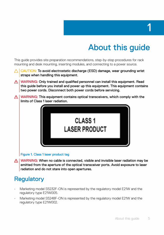
WARNING: This equipment contains optical transceivers, which comply with the limits of Class 1 laser radiation.
Figure 1. Class 1 laser product tag
WARNING: When no cable is connected, visible and invisible laser radiation may be emitted from the aperture of the optical transceiver ports. Avoid exposure to laser radiation and do not stare into open apertures.
Regulatory
• Marketing model S5232F-ON is represented by the regulatory model E21W and the regulatory type E21W005.
• Marketing model S5248F-ON is represented by the regulatory model E21W and the regulatory type E21W002.
1
About this guide 5
• Marketing model S5224F-ON is represented by the regulatory model E21W and the regulatory type E21W003.
• Marketing model S5296F-ON is represented by the regulatory model E26W and the regulatory type E26W001.
• Marketing model S5212F-ON is represented by the regulatory model E29W and the regulatory type E29W001.
Topics:
• Related documents
• Information symbols
Related documents
For more information about the S5200F-ON Series (S5232F-ON, S5248F-ON, S5296F-ON, S5224F-ON, and S5212F-ON) switches, see the following documents.
• OS10 Enterprise Edition Release Notes
• OS10 Enterprise Edition User Guide
• S5200F-ON Series Installation Guide
• S5200F-ON Series Release Notes
• S5200-ON Series BMC User Guide
• Open Networking Hardware Diagnostic Guide
NOTE: For the most recent documentation, see the support site: www.dell.com/support.
Information symbols
This book uses the following information symbols:
NOTE: The Note icon signals important operational information.
CAUTION: The Caution icon signals information about situations that could result in equipment damage or loss of data.
WARNING: The Warning icon signals information about hardware handling that could result in injury.
WARNING: The ESD Warning icon requires that you take electrostatic precautions when handling the device.
6 About this guide
Site preparationsThe 5200F-ON Series (S5232F-ON, S5248F-ON, S5296F-ON, S5224F-ON, and S5212F-ON) switch is suitable for installation as part of a common bond network (CBN).
You can install the switch in:
• Network telecommunication facilities
• Data centers
• Other locations where the National Electric Code (NEC) applies
For more information about the S5200F-ON Series switch specifications, see Specifications.
NOTE: Install the switch into a rack or cabinet before installing any additional components such as cables or optics.
Topics:
• Site selection
• Cabinet placement
• Rack mounting
• Switch ground
• Fans and airflow
• Power
• Storing components
Site selection
Install your equipment in restricted access areas. A restricted access area is one where service personnel can only gain access using a special tool, lock, key, or other means of security. The authority responsible for the location controls access to the restricted area.
2
Site preparations 7
Ensure that the area where you install your switch meets the following safety requirements:
• Near an adequate power source. Connect the switch to the appropriate branch circuit protection according to your local electrical codes.
• Environmental—switch location—continuous temperature range is from 0°C to 45°C (32°F to 113°F).
• Operating humidity is from 5 to 85 percent noncondensing, continuous.
• In a dry, clean, well-ventilated, and temperature-controlled room, away from heat sources such as hot cooling vents or direct sunlight
• Away from sources of severe electromagnetic noise
• Positioned in a rack or cabinet, or on a desktop with adequate space in the front, back, and sides for proper ventilation and access
• Install the switch in information technology rooms in accordance with Article 645 of the National Electrical Code and NFPA 75.
For more information about switch storage and environmental temperatures, see Specifications.
Cabinet placement
Install the S5200F-ON Series switch only in indoor cabinets designed for use in a controlled environment.
Do not install the switch in outside cabinets. For cabinet placement requirements, see Site selection.
The cabinet must meet minimum size requirements. Airflow must be in accordance with the Electronic Industries Alliance (EIA) standard. Ensure that there is a minimum of 5 inches (12.7 cm) between the intake and exhaust vents and the cabinet wall.
Rack mounting
When you prepare your equipment rack, ensure that the rack is grounded. Ground the equipment rack to the same ground point the power service in your area uses. The ground path must be permanent.
Switch ground
Dell EMC recommends grounding your switch. Use the S5200F-ON Series switch in a CBN.
8 Site preparations
Fans and airflow
Fan installation is completed as part of the Factory Install based on the stock keeping unit (SKU) type. The S5200F-ON Series switch has SKUs that support the following configurations:
• AC PSU with fan airflow from the I/O to the PSU—normal
• AC PSU with fan airflow from the PSU to the I/O—reverse
• DC fan unit with airflow from the I/O to the PSU—normal
• DC fan unit with fan airflow from the PSU to the I/O—reverse
Be sure to order the fans suitable to support your site’s ventilation. Use a single type of airflow fan in your switch. Do not mix reverse and normal airflows in a single switch.
For proper ventilation, position the switch in an equipment rack or cabinet with a minimum of 5 inches (12.7 cm) of clearance around the exhaust vents. The fan speed varies based on internal temperature monitoring. The switch never intentionally turns off the fans.
Power
To connect the switch to the applicable power source, use the appropriate power cable. An AC power cable is included with the switch.
When installing AC or DC switches, follow the requirements of the National Electrical Code ANSI/NFPA 70, where applicable.
The switch is powered-up when the power cable is connected between the switch and the power source.
CAUTION: Always disconnect the power cable before you service the power supply slots. The switch has multiple power cables. Before servicing, ensure that all power cables are disconnected.
CAUTION: On the AC switch, use the power supply cable as the main disconnect device. Ensure that the socket-outlet is located/installed near the equipment and is easily accessible.
NOTE: Module power is software controlled. You do not see module LEDs when the switch powers up in the open network install environment (ONIE).
Site preparations 9
Storing components
If you do not install your S5200F-ON Series switch and components immediately, properly store the switch and all components following these guidelines:
• Storage location temperature must remain constant. The storage range is from -40° to 70°C (-40° to 158°F).
• Store on a dry surface or floor, away from direct sunlight, heat, and air conditioning ducts.
• Store in a dust-free environment.
NOTE: ESD damage can occur when components are mishandled. Always wear an ESD-preventive wrist or heel ground strap when handling the switch and its accessories. After you remove the original packaging, place the S5200F-ON Series switch and its components on an anti-static surface.
10 Site preparations
S5200F-ON Series switch Installation
To install the S5200F-ON Series (S5232F-ON, S5248F-ON, S5296F-ON, S5224F-ON, and S5212F-ON) switch, complete the installation procedures in the order presented in this section.
Always handle the switch and its components with care. Avoid dropping the switch or any field replaceable units (FRUs).
NOTE: ESD damage can occur if components are mishandled. Always wear an ESD-preventive wrist or heel ground strap when handling the switch and its components. As with all electrical devices of this type, take all the necessary safety precautions to prevent injury when installing this switch.
Topics:
• Unpack
• Ground cable
• Rack or cabinet installation
• One-half U front-rack installation
• One U ReadyRails installation
• Two U four-post rack assembly
• DC power connections
• S5212F-ON only DC power connections
• Optics installation
• Switch power-up
• After switch installation
3
S5200F-ON Series switch Installation 11
Unpack
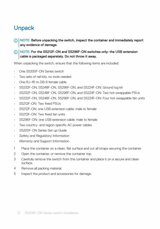
NOTE: Before unpacking the switch, inspect the container and immediately report any evidence of damage.
NOTE: For the S5212F-ON and S5296F-ON switches only: the USB extension cable is packaged separately. Do not throw it away.
When unpacking the switch, ensure that the following items are included:
• One S5200F-ON Series switch
• Two sets of rail kits, no tools needed
• One RJ-45 to DB-9 female cable
• S5232F-ON, S5248F-ON, S5296F-ON, and S5224F-ON: Ground lug kit
• S5232F-ON, S5248F-ON, S5296F-ON, and S5224F-ON: Two hot-swappable PSUs
• S5232F-ON, S5248F-ON, S5296F-ON, and S5224F-ON: Four hot-swappable fan units
• S5212F-ON: Two fixed PSUs
• S5212F-ON: one USB extension cable; male to female
• S5212F-ON: Two fixed fan units
• S5296F-ON: one USB extension cable; male to female
• Two country- and region-specific AC power cables
• S5200F-ON Series Set-up Guide
• Safety and Regulatory Information
• Warranty and Support Information
1 Place the container on a clean, flat surface and cut all straps securing the container.
2 Open the container, or remove the container top.
3 Carefully remove the switch from the container and place it on a secure and clean surface.
4 Remove all packing material.
5 Inspect the product and accessories for damage.
12 S5200F-ON Series switch Installation
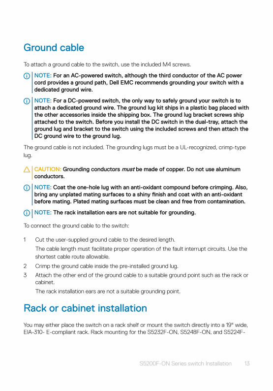
Ground cable
To attach a ground cable to the switch, use the included M4 screws.
NOTE: For an AC-powered switch, although the third conductor of the AC power cord provides a ground path, Dell EMC recommends grounding your switch with a dedicated ground wire.
NOTE: For a DC-powered switch, the only way to safely ground your switch is to attach a dedicated ground wire. The ground lug kit ships in a plastic bag placed with the other accessories inside the shipping box. The ground lug bracket screws ship attached to the switch. Before you install the DC switch in the dual-tray, attach the ground lug and bracket to the switch using the included screws and then attach the DC ground wire to the ground lug.
The ground cable is not included. The grounding lugs must be a UL-recognized, crimp-type lug.
CAUTION: Grounding conductors must be made of copper. Do not use aluminum conductors.
NOTE: Coat the one-hole lug with an anti-oxidant compound before crimping. Also, bring any unplated mating surfaces to a shiny finish and coat with an anti-oxidant before mating. Plated mating surfaces must be clean and free from contamination.
NOTE: The rack installation ears are not suitable for grounding.
To connect the ground cable to the switch:
1 Cut the user-supplied ground cable to the desired length.
The cable length must facilitate proper operation of the fault interrupt circuits. Use the shortest cable route allowable.
2 Crimp the ground cable inside the pre-installed ground lug.
3 Attach the other end of the ground cable to a suitable ground point such as the rack or cabinet.
The rack installation ears are not a suitable grounding point.
Rack or cabinet installation
You may either place the switch on a rack shelf or mount the switch directly into a 19" wide, EIA-310- E-compliant rack. Rack mounting for the S5232F-ON, S5248F-ON, and S5224F-
S5200F-ON Series switch Installation 13
ON switches includes four-post, two-post, round threaded holes, or square holes. The ReadyRails system is provided for 1U front-rack and two-post installations.
Do not use the ReadyRails system for the S5296F-ON or S5212F-ON switches. For the S5296F-ON switch, see Two U four-post rack assembly. For the S5212F-ON switch, see One-half U front-rack installation.
The ReadyRails system includes two separately packaged rail assemblies. To begin installation, separate each rail assembly by sliding the inside rail out of the outside rail.
WARNING: This guide is a condensed reference. Read the safety instructions in your Safety, Environmental, and Regulatory information booklet before you begin.
NOTE: The illustrations in this section are not intended to represent a specific switch.
NOTE: Do not the use the mounted ReadyRails as a shelf or a workplace.
Rack mount safety considerations
• Rack loading—Overloading or uneven loading of racks may result in shelf or rack failure, possibly damaging the equipment and causing personal injury. Stabilize racks in a permanent location before loading begins. Mount the components starting at the bottom of the rack, then work to the top. Do not exceed your rack’s load rating.
• Power considerations—Connect only to the power source specified on the unit. When you install multiple electrical components in a rack, ensure that the total component power ratings do not exceed the circuit capabilities. Overloaded power sources and extension cables are fire and shock hazards.
• Elevated ambient temperature—If you install the switch in a closed rack assembly, the operating temperature of the rack environment may be greater than the room ambient temperature. Use care not to exceed the 45°C (113°F) maximum ambient temperature of the switch.
• Reduced airflow—Do not compromise the amount of airflow needed for safe operation of the equipment. Install the equipment in the rack so that the equipment constantly has the correct amount of airflow surrounding it.
• Reliable earthing—Maintain reliable earthing of rack-mounted equipment. Pay particular attention to the supply connections other than the direct connections to the branch circuit, for example: use of power strips.
• Do not mount the equipment with the fan panel facing in the downward position.
14 S5200F-ON Series switch Installation
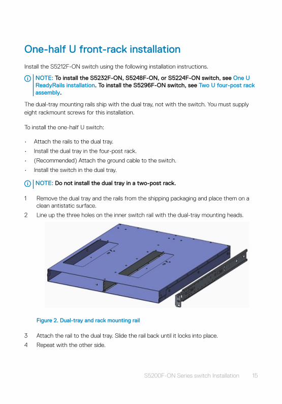
One-half U front-rack installation
Install the S5212F-ON switch using the following installation instructions.
NOTE: To install the S5232F-ON, S5248F-ON, or S5224F-ON switch, see One U ReadyRails installation. To install the S5296F-ON switch, see Two U four-post rack assembly.
The dual-tray mounting rails ship with the dual tray, not with the switch. You must supply eight rackmount screws for this installation.
To install the one-half U switch:
• Attach the rails to the dual tray.
• Install the dual tray in the four-post rack.
• (Recommended) Attach the ground cable to the switch.
• Install the switch in the dual tray.
NOTE: Do not install the dual tray in a two-post rack.
1 Remove the dual tray and the rails from the shipping packaging and place them on a clean antistatic surface.
2 Line up the three holes on the inner switch rail with the dual-tray mounting heads.
Figure 2. Dual-tray and rack mounting rail
3 Attach the rail to the dual tray. Slide the rail back until it locks into place.
4 Repeat with the other side.
S5200F-ON Series switch Installation 15
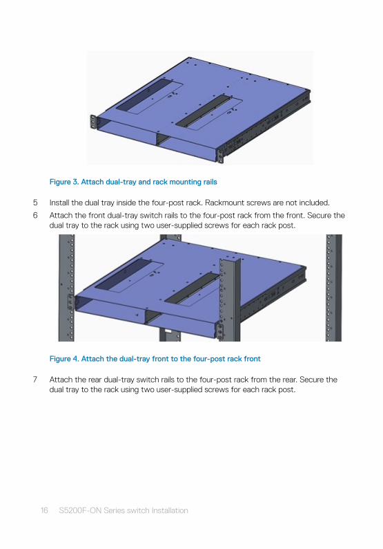
Figure 3. Attach dual-tray and rack mounting rails
5 Install the dual tray inside the four-post rack. Rackmount screws are not included.
6 Attach the front dual-tray switch rails to the four-post rack from the front. Secure the dual tray to the rack using two user-supplied screws for each rack post.
Figure 4. Attach the dual-tray front to the four-post rack front
7 Attach the rear dual-tray switch rails to the four-post rack from the rear. Secure the dual tray to the rack using two user-supplied screws for each rack post.
16 S5200F-ON Series switch Installation
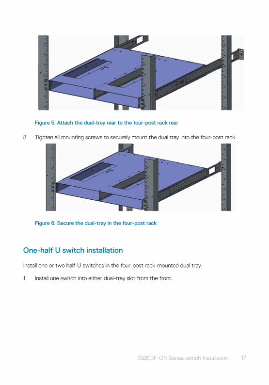
Figure 5. Attach the dual-tray rear to the four-post rack rear
8 Tighten all mounting screws to securely mount the dual tray into the four-post rack.
Figure 6. Secure the dual-tray in the four-post rack
One-half U switch installation
Install one or two half-U switches in the four-post rack-mounted dual tray.
1 Install one switch into either dual-tray slot from the front.
S5200F-ON Series switch Installation 17
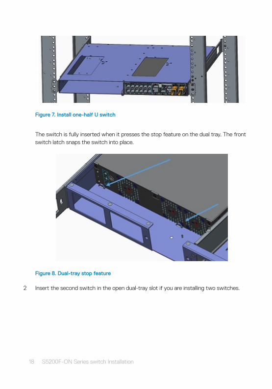
Figure 7. Install one-half U switch
The switch is fully inserted when it presses the stop feature on the dual tray. The front switch latch snaps the switch into place.
Figure 8. Dual-tray stop feature
2 Insert the second switch in the open dual-tray slot if you are installing two switches.
18 S5200F-ON Series switch Installation
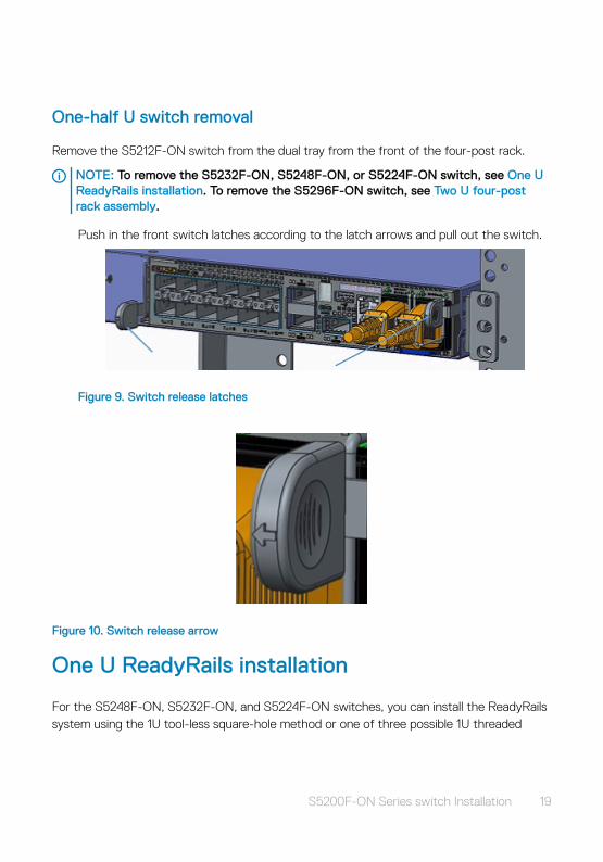
One-half U switch removal
Remove the S5212F-ON switch from the dual tray from the front of the four-post rack.
NOTE: To remove the S5232F-ON, S5248F-ON, or S5224F-ON switch, see One U ReadyRails installation. To remove the S5296F-ON switch, see Two U four-post rack assembly.
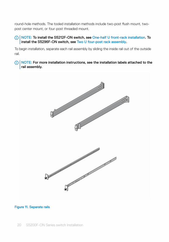
Push in the front switch latches according to the latch arrows and pull out the switch.
Figure 9. Switch release latches
Figure 10. Switch release arrow
One U ReadyRails installation
For the S5248F-ON, S5232F-ON, and S5224F-ON switches, you can install the ReadyRails system using the 1U tool-less square-hole method or one of three possible 1U threaded
S5200F-ON Series switch Installation 19
round-hole methods. The tooled installation methods include two-post flush mount, two-post center mount, or four-post threaded mount.
NOTE: To install the S5212F-ON switch, see One-half U front-rack installation. To install the S5296F-ON switch, see Two U four-post rack assembly.
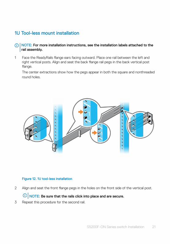
To begin installation, separate each rail assembly by sliding the inside rail out of the outside rail.
NOTE: For more installation instructions, see the installation labels attached to the rail assembly.
Figure 11. Separate rails
20 S5200F-ON Series switch Installation
1U Tool-less mount installation
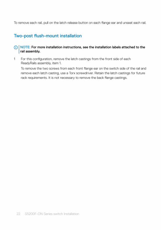
NOTE: For more installation instructions, see the installation labels attached to the rail assembly.
1 Face the ReadyRails flange ears facing outward. Place one rail between the left and right vertical posts. Align and seat the back flange rail pegs in the back vertical post flange.
The center extractions show how the pegs appear in both the square and nonthreaded round holes.
Figure 12. 1U tool-less installation
2 Align and seat the front flange pegs in the holes on the front side of the vertical post.
NOTE: Be sure that the rails click into place and are secure.
3 Repeat this procedure for the second rail.
S5200F-ON Series switch Installation 21
To remove each rail, pull on the latch release button on each flange ear and unseat each rail.
Two-post flush-mount installation
NOTE: For more installation instructions, see the installation labels attached to the rail assembly.
1 For this configuration, remove the latch castings from the front side of each ReadyRails assembly, item 1.
To remove the two screws from each front flange ear on the switch side of the rail and remove each latch casting, use a Torx screwdriver. Retain the latch castings for future rack requirements. It is not necessary to remove the back flange castings.
22 S5200F-ON Series switch Installation
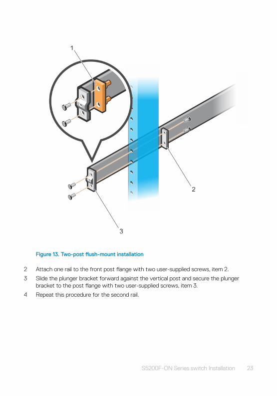
Figure 13. Two-post flush-mount installation
2 Attach one rail to the front post flange with two user-supplied screws, item 2.
3 Slide the plunger bracket forward against the vertical post and secure the plunger bracket to the post flange with two user-supplied screws, item 3.
4 Repeat this procedure for the second rail.
S5200F-ON Series switch Installation 23
Two-post center-mount installation
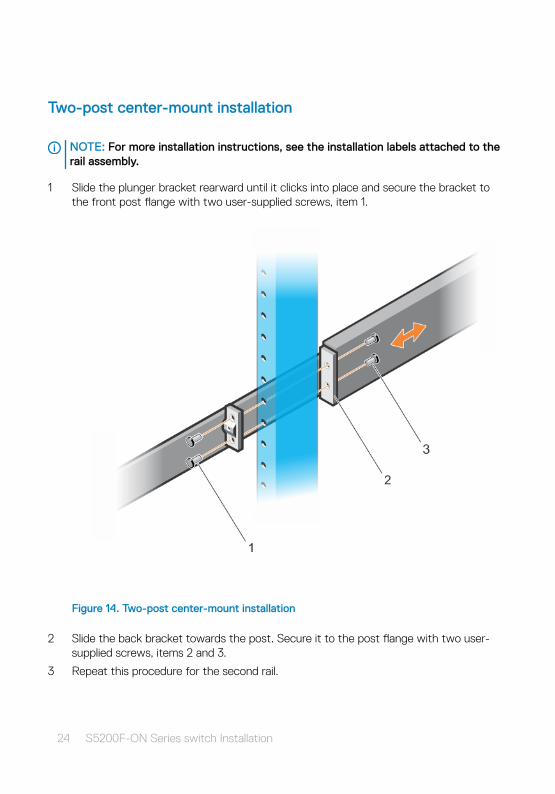
NOTE: For more installation instructions, see the installation labels attached to the rail assembly.
1 Slide the plunger bracket rearward until it clicks into place and secure the bracket to the front post flange with two user-supplied screws, item 1.
Figure 14. Two-post center-mount installation
2 Slide the back bracket towards the post. Secure it to the post flange with two user-supplied screws, items 2 and 3.
3 Repeat this procedure for the second rail.
24 S5200F-ON Series switch Installation
Four-post threaded installation
NOTE: For more installation instructions, see the installation labels attached to the rail assembly.
1 Remove the latch castings from each end of the ReadyRails assemblies. To remove the two screws each latch casting, use a Torx driver.
Retain the latch castings for future rack requirements.
S5200F-ON Series switch Installation 25
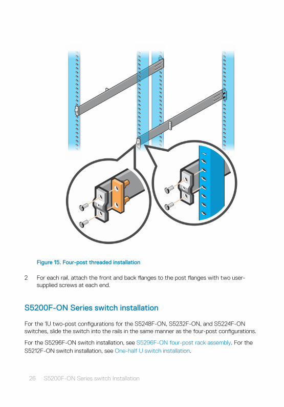
Figure 15. Four-post threaded installation
2 For each rail, attach the front and back flanges to the post flanges with two user-supplied screws at each end.
S5200F-ON Series switch installation
For the 1U two-post configurations for the S5248F-ON, S5232F-ON, and S5224F-ON switches, slide the switch into the rails in the same manner as the four-post configurations.
For the S5296F-ON switch installation, see S5296F-ON four-post rack assembly. For the S5212F-ON switch installation, see One-half U switch installation.
26 S5200F-ON Series switch Installation

1U front-rack installationConfigure the rails that are attached to the switch.
1 NOTE: For more information, see the installation instruction labels on the rail.
Attach the inner switch rails to the S5200F-ON Series switch.
Line up the rail with the mounting heads and attach the rail to the chassis. Slide the rail back until it locks into place. The following shows the detail of the front standoff with the locking tab:
S5200F-ON Series switch Installation 27
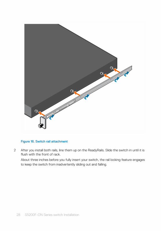
Figure 16. Switch rail attachment
2 After you install both rails, line them up on the ReadyRails. Slide the switch in until it is flush with the front of rack.
About three inches before you fully insert your switch, the rail locking feature engages to keep the switch from inadvertently sliding out and falling.
28 S5200F-ON Series switch Installation
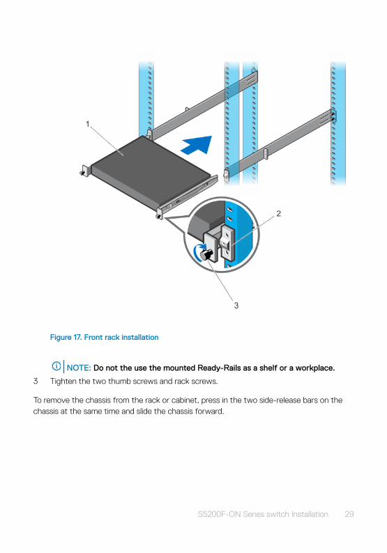
Figure 17. Front rack installation
NOTE: Do not the use the mounted Ready-Rails as a shelf or a workplace.
3 Tighten the two thumb screws and rack screws.
To remove the chassis from the rack or cabinet, press in the two side-release bars on the chassis at the same time and slide the chassis forward.
S5200F-ON Series switch Installation 29
Two U four-post rack assembly
Due to the chassis weight, the S5296F-ON switch does not support a two-post rack installation; you must install the S5296F-ON in a four-post rack.
NOTE: To install the S5212F-ON, see One-half U front-rack installation. To install the S5232F-ON, S5248F-ON, or S5224F-ON switch, see One U ReadyRails installation.
To install in a four-post rack, follow the instructions in your rack frame kit. In a four-post rack, the maximum distance between the front and back vertical posts is 36 inches (91.44 cm); the minimum distance is 24 inches (60.96).
CAUTION: Use two people, an equipment lift, or pallet jack when lifting or moving the chassis. Install the chassis into the rack before inserting the chassis components. Lift the chassis only from the bottom. Lifting by the chassis shelves or power supply openings might damage the chassis.
Four-post rack mount
Rack mounting safety considerations
WARNING: To prevent bodily injury when mounting or servicing this unit in a rack, take special precautions to ensure that the chassis remains stable. The following guidelines are provided to ensure your safety:
• If your chassis is the only unit in the rack, mount it at the bottom of the rack.
• When mounting this unit in a partially filled rack, load the rack from the bottom to the top with the heaviest component at the bottom of the rack.
• If the rack comes with stabilizing devices, install the stabilizers before mounting or servicing the unit in the rack.
• If the chassis ships with blanks, remove the blanks from each slot before lifting the chassis.
WARNING: These instructions are a condensed reference. Read the safety instructions in your Safety, Environmental, and Regulatory information booklet before you begin.
NOTE: The illustrations in this document are not intended to represent a specific switch.
30 S5200F-ON Series switch Installation
Rack mount safety considerations
• Rack loading—Overloading or uneven loading of racks may result in shelf or rack failure, possibly damaging the equipment and causing personal injury. Stabilize racks in a permanent location before loading begins. Mount the components starting at the bottom of the rack, then work to the top. Do not exceed your rack’s load rating.
• Power considerations—Connect only to the power source specified on the unit. When you install multiple electrical components in a rack, ensure that the total component power ratings do not exceed the circuit capabilities. Overloaded power sources and extension cables present fire and shock hazards.
• Elevated ambient temperature—If you install the switch in a closed rack assembly, the operating temperature of the rack environment may be greater than the room ambient temperature. Use care not to exceed the 45°C (113°F) maximum ambient temperature of the switch.
• Reduced airflow—Do not compromise the amount of airflow needed for safe operation of the equipment. Install the equipment in the rack so that the equipment constantly has the correct amount of airflow surrounding it.
• Reliable earthing—Maintain reliable earthing of rack-mounted equipment. Pay particular attention to the supply connections other than the direct connections to the branch circuit, for example; use of power strips.
• Do not mount the equipment with the fan panel facing in the downward position.
Chassis installation and removal
1 Align the chassis with the rails and slide the chassis into the rack.
2 Tighten the screws on each side of the chassis’s front panel, items 1 and 2.
To remove the chassis from the rack, loosen the screws and slide the chassis out of the rack.
S5200F-ON Series switch Installation 31
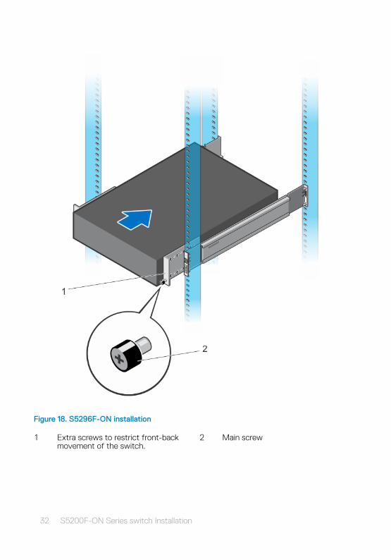
Figure 18. S5296F-ON installation
1 Extra screws to restrict front-back movement of the switch.
2 Main screw
32 S5200F-ON Series switch Installation
DC power connections
NOTE: Use the following instructions for all S5200F-ON Series switches except for the S5212F-ON switch. To connect DC power to the S5212F-ON switch, see S5212F-ON only DC power connections.
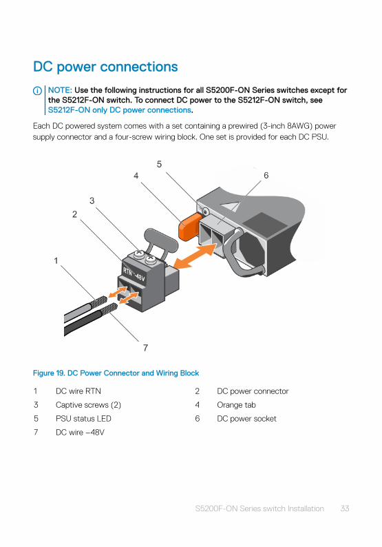
Each DC powered system comes with a set containing a prewired (3-inch 8AWG) power supply connector and a four-screw wiring block. One set is provided for each DC PSU.
Figure 19. DC Power Connector and Wiring Block
1 DC wire RTN 2 DC power connector
3 Captive screws (2) 4 Orange tab
5 PSU status LED 6 DC power socket
7 DC wire –48V
S5200F-ON Series switch Installation 33
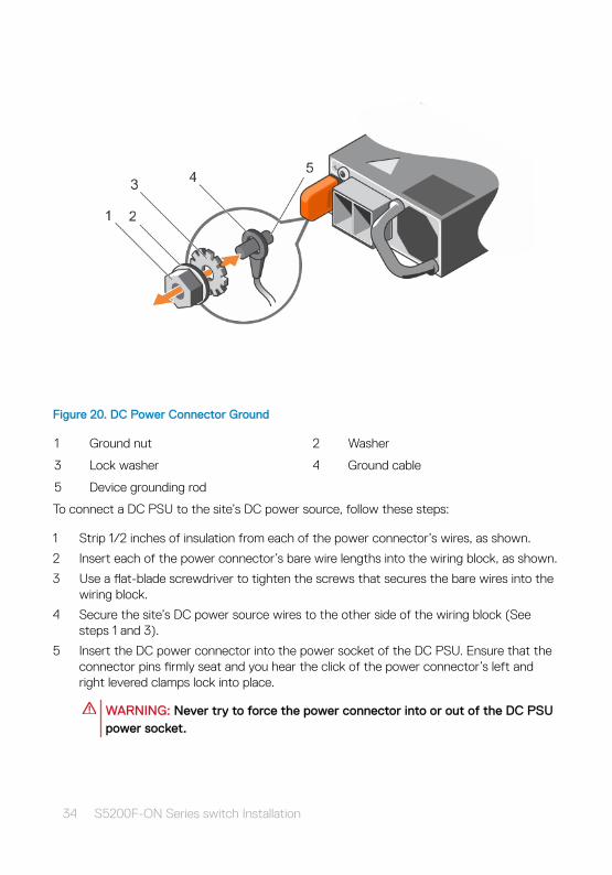
Figure 20. DC Power Connector Ground
1 Ground nut 2 Washer
3 Lock washer 4 Ground cable
5 Device grounding rod
To connect a DC PSU to the site’s DC power source, follow these steps:
1 Strip 1/2 inches of insulation from each of the power connector’s wires, as shown.
2 Insert each of the power connector’s bare wire lengths into the wiring block, as shown.
3 Use a flat-blade screwdriver to tighten the screws that secures the bare wires into the wiring block.
4 Secure the site’s DC power source wires to the other side of the wiring block (See steps 1 and 3).
5 Insert the DC power connector into the power socket of the DC PSU. Ensure that the connector pins firmly seat and you hear the click of the power connector’s left and right levered clamps lock into place.
WARNING: Never try to force the power connector into or out of the DC PSU power socket.
34 S5200F-ON Series switch Installation
NOTE: To remove the power connector from a DC PSU, squeeze the levers on both sides of the connector. Doing so disengages the power connector’s clamps. While continuing to squeeze, pull the power connector from the DC PSU socket.
S5212F-ON only DC power connections
NOTE: Use the following instructions for the S5212F-ON switch only. For all other S5200F-ON Series switches, see DC power connections.
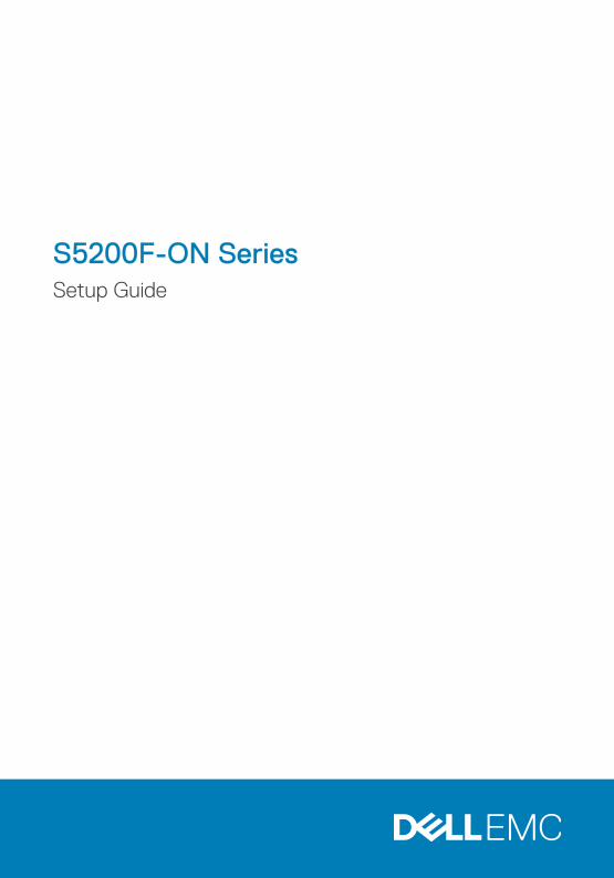
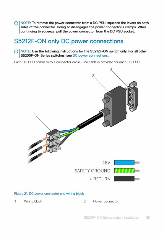
Each DC PSU comes with a connector cable. One cable is provided for each DC PSU.
Figure 21. DC power connector and wiring block
1 Wiring block 2 Power connector
S5200F-ON Series switch Installation 35
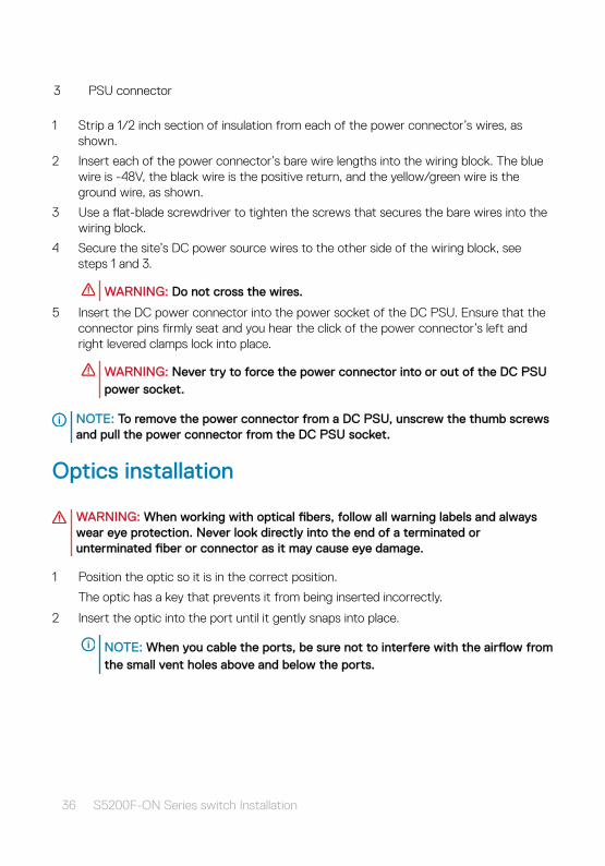
3 PSU connector
1 Strip a 1/2 inch section of insulation from each of the power connector’s wires, as shown.
2 Insert each of the power connector’s bare wire lengths into the wiring block. The blue wire is -48V, the black wire is the positive return, and the yellow/green wire is the ground wire, as shown.
3 Use a flat-blade screwdriver to tighten the screws that secures the bare wires into the wiring block.
4 Secure the site’s DC power source wires to the other side of the wiring block, see steps 1 and 3.
WARNING: Do not cross the wires.
5 Insert the DC power connector into the power socket of the DC PSU. Ensure that the connector pins firmly seat and you hear the click of the power connector’s left and right levered clamps lock into place.
WARNING: Never try to force the power connector into or out of the DC PSU power socket.
NOTE: To remove the power connector from a DC PSU, unscrew the thumb screws and pull the power connector from the DC PSU socket.
Optics installation
WARNING: When working with optical fibers, follow all warning labels and always wear eye protection. Never look directly into the end of a terminated or unterminated fiber or connector as it may cause eye damage.
1 Position the optic so it is in the correct position.
The optic has a key that prevents it from being inserted incorrectly.
2 Insert the optic into the port until it gently snaps into place.
NOTE: When you cable the ports, be sure not to interfere with the airflow from the small vent holes above and below the ports.
36 S5200F-ON Series switch Installation
Optics removal
Remove an optic by pushing the tab on the optic and sliding the optic from the port.
When removing optics with direct attach cables (DACs) from the port, pull the release tab firmly and steadily. Before pulling the release tab, you may need to gently push the optic into the port to ensure that it is seated properly. Do not jerk or tug repeatedly on the tab.
Switch power-up
Supply power to the S5200F-ON Series switch after you mount it in a rack or cabinet.
Reinspect your switch before power up. Verify the following:
• The equipment is properly secured to the rack. Dell EMC recommends properly grounding the switch.
• The ambient temperature around the unit, which may be higher than the room temperature, is within the limits specified for the S5200F-ON Series switch, see Specifications.
• There is sufficient airflow around the unit.
• The input circuits are correctly sized for the loads and that you use sufficient overcurrent protection devices.
• All protective covers are in place.
CAUTION: Do not power up the switch if you did not install a fan module.
NOTE: A US AC power cable is included for powering up an AC power supply. You must order all other power cables separately.
NOTE: ESD damage can occur if components are mishandled. Always wear an ESD-preventive wrist or heel ground strap when handling the switch and its components.
Power up sequence
When the switch powers up, the fans immediately come on at high speed. The fan speed slows as the switch continues to boot up.
S5200F-ON Series switch Installation 37
After switch installation
After you have securely installed and powered on the S5200F-ON Series switch:
• If you are using Dell EMC software, see switch documentation at www.dell.com/support.
• If you are using third-party software, see ONIE documentation at www.onie.org.
38 S5200F-ON Series switch Installation
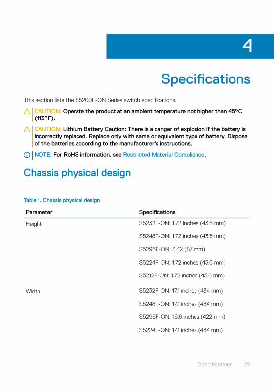
SpecificationsThis section lists the S5200F-ON Series switch specifications.
CAUTION: Operate the product at an ambient temperature not higher than 45°C (113°F).
CAUTION: Lithium Battery Caution: There is a danger of explosion if the battery is incorrectly replaced. Replace only with same or equivalent type of battery. Dispose of the batteries according to the manufacturer's instructions.
NOTE: For RoHS information, see Restricted Material Compliance.
Chassis physical design
Table 1. Chassis physical design
Parameter Specifications
Height S5232F-ON: 1.72 inches (43.6 mm)
S5248F-ON: 1.72 inches (43.6 mm)
S5296F-ON: 3.42 (87 mm)
S5224F-ON: 1.72 inches (43.6 mm)
S5212F-ON: 1.72 inches (43.6 mm)
Width S5232F-ON: 17.1 inches (434 mm)
S5248F-ON: 17.1 inches (434 mm)
S5296F-ON: 16.6 inches (422 mm)
S5224F-ON: 17.1 inches (434 mm)
4
Specifications 39
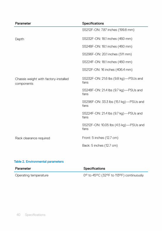
Parameter Specifications
S5212F-ON: 7.87 inches (199.8 mm)
Depth S5232F-ON: 18.1 inches (460 mm)
S5248F-ON: 18.1 inches (460 mm)
S5296F-ON: 20.1 inches (511 mm)
S5224F-ON: 18.1 inches (460 mm)
S5212F-ON: 16 inches (406.4 mm)
Chassis weight with factory-installed components
S5232F-ON: 21.6 lbs (9.8 kg)—PSUs and fans
S5248F-ON: 21.4 lbs (9.7 kg)—PSUs and fans
S5296F-ON: 33.3 lbs (15.1 kg)—PSUs and fans
S5224F-ON: 21.4 lbs (9.7 kg)—PSUs and fans
S5212F-ON: 10.05 lbs (4.5 kg)—PSUs and fans
Rack clearance required Front: 5 inches (12.7 cm)
Back: 5 inches (12.7 cm)
Table 2. Environmental parameters
Parameter Specifications
Operating temperature 0° to 45°C (32°F to 113°F) continuously
40 Specifications
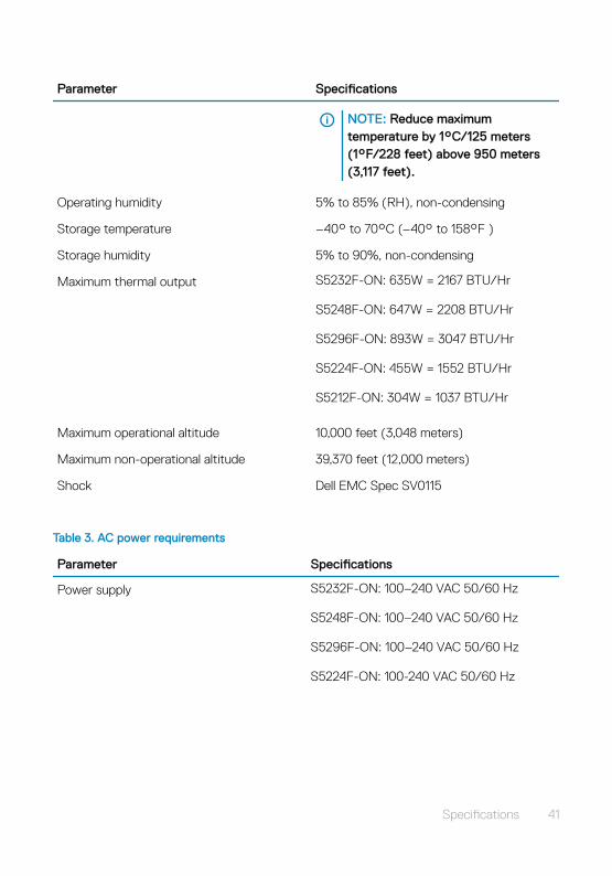
Parameter Specifications
NOTE: Reduce maximum temperature by 1°C/125 meters (1°F/228 feet) above 950 meters (3,117 feet).
Operating humidity 5% to 85% (RH), non-condensing
Storage temperature –40° to 70°C (–40° to 158°F )
Storage humidity 5% to 90%, non-condensing
Maximum thermal output S5232F-ON: 635W = 2167 BTU/Hr
S5248F-ON: 647W = 2208 BTU/Hr
S5296F-ON: 893W = 3047 BTU/Hr
S5224F-ON: 455W = 1552 BTU/Hr
S5212F-ON: 304W = 1037 BTU/Hr
Maximum operational altitude 10,000 feet (3,048 meters)
Maximum non-operational altitude 39,370 feet (12,000 meters)
Shock Dell EMC Spec SV0115
Table 3. AC power requirements
Parameter Specifications
Power supply S5232F-ON: 100–240 VAC 50/60 Hz
S5248F-ON: 100–240 VAC 50/60 Hz
S5296F-ON: 100–240 VAC 50/60 Hz
S5224F-ON: 100-240 VAC 50/60 Hz
Specifications 41
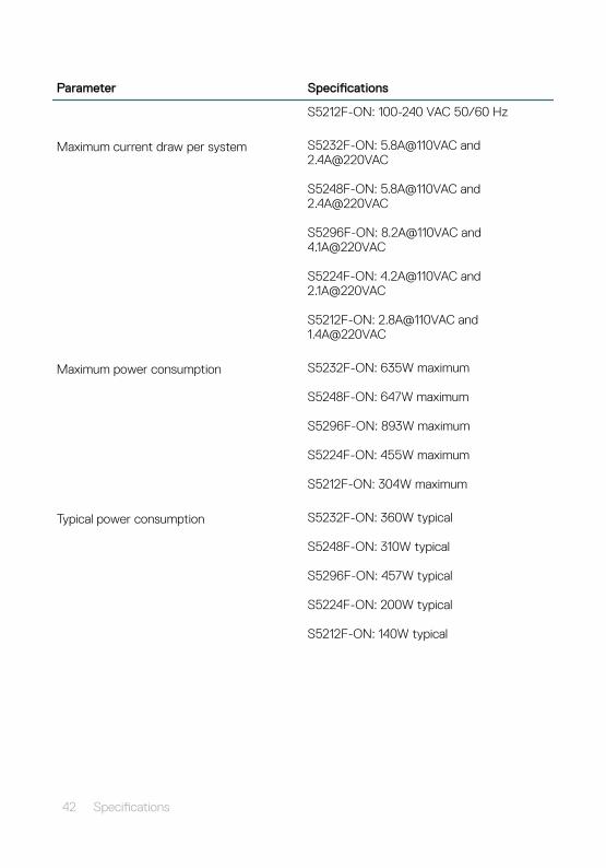
Parameter Specifications
S5212F-ON: 100-240 VAC 50/60 Hz
Maximum current draw per system S5232F-ON: 5.8A@110VAC and 2.4A@220VAC
S5248F-ON: 5.8A@110VAC and 2.4A@220VAC
S5296F-ON: 8.2A@110VAC and 4.1A@220VAC
S5224F-ON: 4.2A@110VAC and 2.1A@220VAC
S5212F-ON: 2.8A@110VAC and 1.4A@220VAC
Maximum power consumption S5232F-ON: 635W maximum
S5248F-ON: 647W maximum
S5296F-ON: 893W maximum
S5224F-ON: 455W maximum
S5212F-ON: 304W maximum
Typical power consumption S5232F-ON: 360W typical
S5248F-ON: 310W typical
S5296F-ON: 457W typical
S5224F-ON: 200W typical
S5212F-ON: 140W typical
42 Specifications
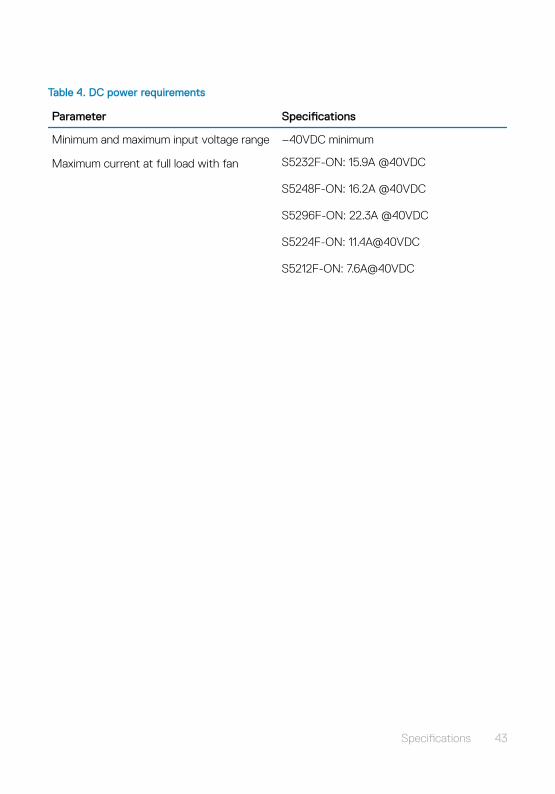
Table 4. DC power requirements
Parameter Specifications
Minimum and maximum input voltage range –40VDC minimum
Maximum current at full load with fan S5232F-ON: 15.9A @40VDC
S5248F-ON: 16.2A @40VDC
S5296F-ON: 22.3A @40VDC
S5224F-ON: 11.4A@40VDC
S5212F-ON: 7.6A@40VDC
Specifications 43

SupportThe support site provides documents and tools to help you effectively use your equipment and mitigate network outages. Through the support site you can obtain technical information, access software upgrades and patches, download available management software, and manage your open cases. The support site provides integrated, secure access to these services.
To access the support site, go to www.dell.com/support/. To display information in your language, scroll down to the bottom of the web page and select your country from the drop-down menu.
• To obtain product-specific information, enter the 7-character service tag, known as a luggage tag, or 11-digit express service code of your switch and click Submit.
To view the chassis service tag or express service code, pull out the tag or enter the show chassis command from the CLI.
• To receive more technical support, click Contact Us. On the Contact Information web page, click Technical Support.
To access switch documentation, go to www.dell.com/manuals/.
To search for drivers and downloads, go to www.dell.com/drivers/.
To participate in community blogs and forums, go to www.dell.com/community.
5
44 Support