Embed Size (px)
Citation preview
Vacuum Release Valvewith Restrictor
D-sub ConnectorFlat Ribbon CablePC WiringSerial Wiring: EX180Serial Wiring: EX510
P.86
Individual WiringP.90
Series SJ3A6
Plug-in Type Connector Connection
Non Plug-in Type Individual Wiring
83
SJ
SY
SV
SYJ
SZ
VP4
S0700
VQ
VQ4
VQ5
VQC
VQZ
SQ
VFS
VFR
VQ7
P0011-P0100-E.qxd 08.9.1 1:54 PM Page 83
JIS symbol
84
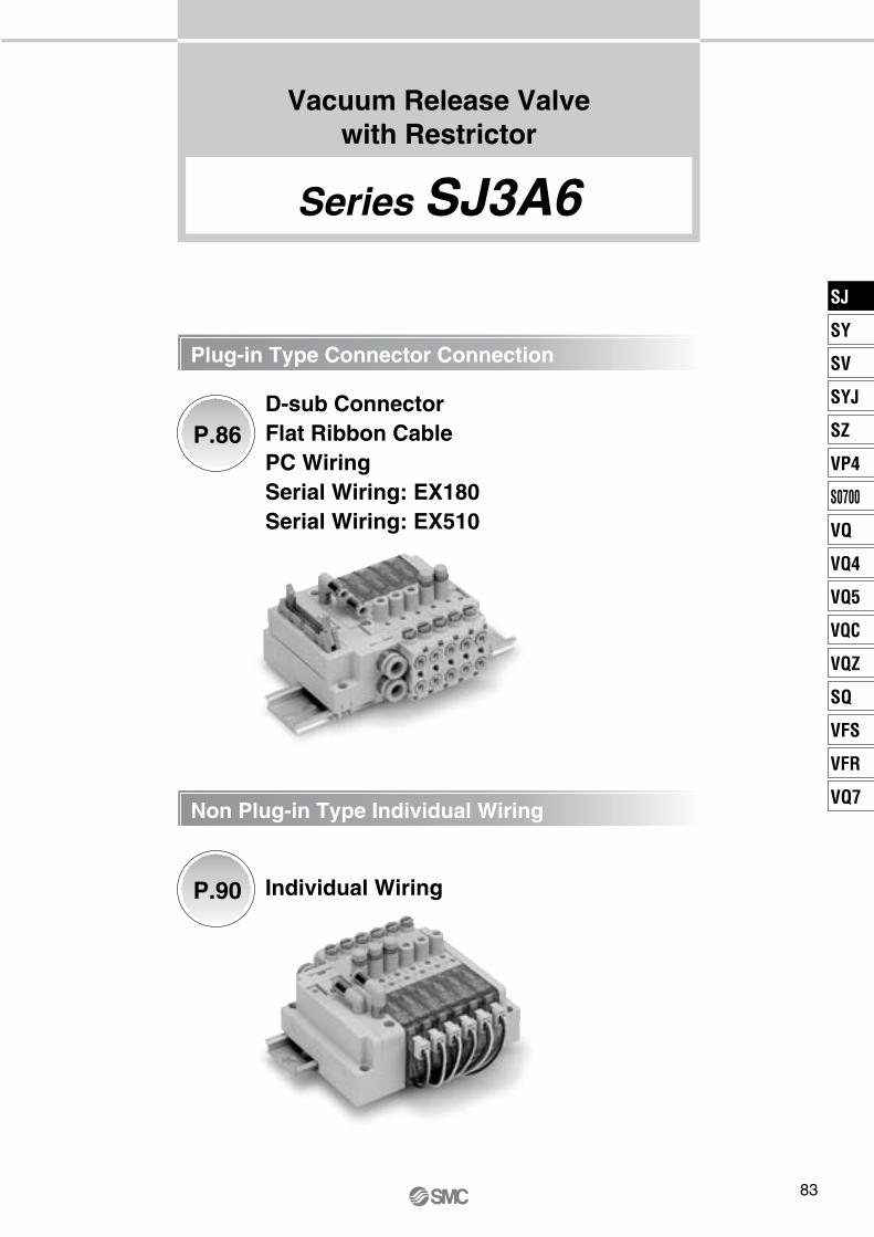
Vacuum Release Valve with RestrictorCommon Specifications
Series SJ3A6Manifold Valve Specifications
Note 1) Can be used with positive pressure to suit the application.Note 2) Please use with pilot X port pressure equal to or higher than the release port 1(P) pressure. Note 3) Impact resistance: No malfunction occurred when it is tested in the axial direction and at the right angles
to the main valve and armature in both energized and de-energized states every once for each condition. (Values at the initial period)
Vibration resistance: No malfunction occurred in a one-sweep test between 45 and 2000 Hz. Test was performed at both energized and de-energized states in the axial direction and at the right angles to the main valve and armature. (Values at the initial period)
Valve constructionFluid
Pilot methodLubricationMounting orientationImpact/Vibration resistance (m/s2) Note 3)
Enclosure
Ambient and fluid temperature (°C)Max. operating frequency (Hz)
Operating pressure range (MPa)
Manual override (Manual operation)
Restrictor operation
3 position 3 port valve with restrictorAir
0.25 to 0.7–100 kPa to 0.7 Note 1)
0.25 to 0.7 Note 2)
–10 to 50 (No freezing)3
Non-locking push typePush-turn locking slotted type
ManualSlotted locking type
External pilot/Pilot valve individual exhaustNot requiredUnrestricted
150/30Dustproof
Release pressure port 1(P)Vacuum pressure port 3/5(E)Pilot X port
∗ For the allowable voltage fluctuation for Z/T type (with power saving circuit), please observe the following range because they have voltage drop due to internal circuit.Z type 24 VDC: –7% to +10%
12 VDC: –4% to +10%T type 24 VDC: –5% to +10%
12 VDC: –6% to +10%
Coil rated voltageAllowable voltage fluctuationPower consumption (W)Surge voltage suppressorIndicator type
StandardWith power saving circuit (Continuous duty type)
24 VDC, 12 VDC±10% of rated voltage∗
0.40.15
DiodeLED
Solenoid Specifications
Flow CharacteristicsFlow Characteristics (When restrictor is fully open)
Valve modelFluid passage2(B) Port size
M5
1(P)→2(B)b
0.19Cv
0.05C [dm3/(s·bar)]
0.40b
0.18Cv
0.10C [dm3/(s·bar)]
0.24
2(B)→3/5(E)
SJ3A6-��-�
Restrictor Flow Characteristics [Fluid passage: 1(P)→2(B)]
Number of restrictor rotations
Flo
w r
ate
[l/m
in (
AN
R)]
120
100
80
60
40
20
543210
Inlet pressure:0.15 MPa
Inlet pressure:0.3 MPa
Inlet pressure:0.5 MPa
Inlet pressure:0.7 MPa
X
PS port
2(B)Vacuum pad port
1(P)Release
pressure port
3/5(E)Vacuum
pressure port
Response Time
Valve model Response time ms (at 0.5 MPa)SJ3A6-��-� 19 or less
Valve model Mass (g)SJ3A6-��-P 79
Mass
P0011-P0100-E.qxd 08.9.1 1:54 PM Page 84
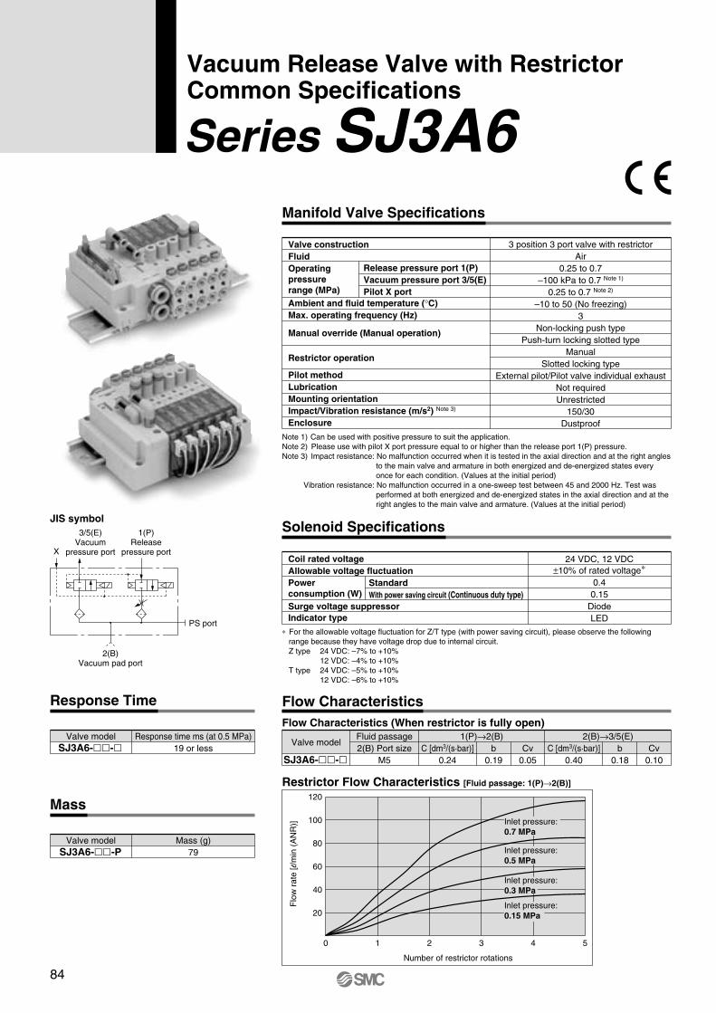
<Filter replacement instructions>
If there are situations such as filter clogging, a drop in suction force, or slow re-sponse time, stop operation and replace the filter. 1. Using a precision driver, remove the filter assembly (!2 or !4) from the main
unit. 2. Turn the filter guide by hand and remove. 3. Replace the filter (!3 or !5) and gently hand tighten the filter guide. At this
time, check that there is no foreign matter on the O-ring of the filter assembly.4. Return the filter assembly to the main unit.
(Tightening torque: 0.12 N·m)
W
!0
o !5 !4
2(B)
1(P)3/5(E)
y t r q e uw !2!3i !1
85
Construction
Vacuum Release Valve with Restrictor Series SJ3A6
PS port
Symbol: F2Vacuum pressure side filter
Symbol: F1Release pressure side filter
11
DescriptionNo. Part no.
Component Parts
Plug
Note
PS port with plug
1
2
3
4
5
6
7
8
DescriptionNo. Material Note
Component Parts
Spool valve assembly
Spool valve assembly
Body
Adaptor plate
Pilot adaptor
Pilot valve assembly
End cover
Restrictor blockassembly Note)
Bottom cover
Light cover
Resin/H-NBR
Resin/H-NBR
Zinc die-cast
Resin
Resin
—
Resin
Resin
A side (for release pressure switching)
B side (for vacuum pressure switching)
—
White
White
—
White
White
9
10
Resin
Resin
White
Light blue
Note) Set the operating torque of the restrictor of the restrictor block assembly to 0.3 N·m or less.
15 Filter
14 Filter assembly
13 Filter
12 Filter assembly
M-5P
SJ3000-107-2A
SJ3000-110-2A
SJ3000-107-1A
SJ3000-110-1A
30 μm Light purple<Vacuum pressure side>, 5 pcs. included
30 μm Light purple<Vacuum pressure side>
1 μm White<Release pressure side>, 5 pcs. included
1 μm White<Release pressure side>
After tightening the plug (M-5P) with a tightening torque of 1 N·m, or manually tightening, use the tightening tool and tighten it by 1/4 turn.
!3!5 Filter (5 pcs. included)!2!4 Filter assembly (with filter)
Filter guide
O-ring
Notch in screw
Filter guide
Filter
O-ring
Notch in screw
Adsorbing and Transferring System Circuit Example
Pressure switch etc.
(Ejector)Vacuum pump
Vacuum pressure switching valve
FilterVacuum side
FilterRelease side
Pad side
SJ3A6
Release pressure switching valve
(Built-in restrictor)
Release air
SJ
SY
SV
SYJ
SZ
VP4
S0700
VQ
VQ4
VQ5
VQC
VQZ
SQ
VFS
VFR
VQ7
P0011-P0100-E.qxd 08.9.1 1:54 PM Page 85
How to Order Valve Manifold Assembly
Ordering example (SS3J3-V60PD2-�)
60 USS3J3 05V
86
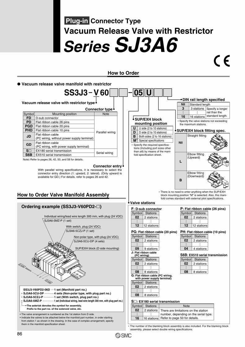
Series SJ3A6Vacuum Release Valve with RestrictorPlug-in Connector Type
How to Order
� Vacuum release valve manifold with restrictor
Vacuum release valve with restrictor type
SymbolFDPD
PGDPHD
JD
GD
S�S6B
Note
Parallel wiring
Serial wiring
Mounting positionD-sub connectorFlat ribbon cable 26 pinsFlat ribbon cable 20 pinsFlat ribbon cable 10 pins
EX180 serial transmissionEX510 serial transmission
Flat ribbon cable(PC wiring, without power supply terminal)
Flat ribbon cable(PC wiring, with power supply terminal)
Note) Refer to pages 26, 42, 50, and 58 for details.
Connector type
Connector entryWith parallel wiring specifications, it is necessary to select the connector entry direction (1: upward, 2: lateral). (Only upward is available for GD.) For details, refer to pages 26 and 42.
∗ Specify the required specifica-tions (Including port sizes other than ø8) by means of the mani-fold specification sheet.
SUP/EXH block mounting position
UDBM∗
U side (2 to 10 stations)D side (2 to 10 stations)Both sides (2 to 16 stations)Special specifications
DIN rail length specified
Specify a longer rail than the standard length.
Standard length3 stations
16 stations
Nil3
16∗ Specify the valve stations not exceeding
the maximum stations.
SUP/EXH block fitting spec.Straight fitting
Elbow fitting(Upward)
Nil
L
B
Elbow fitting(Downward)
∗ There is no need to enter anything when the SUP/EXH block mounting position “M” is selected. Also, this mani-fold comes standard with external pilot specifications.
F: D-sub connector
Valve stations
2 stations
12 stations
Symbol Stations02
12
PG: Flat ribbon cable (20 pins)
2 stations
9 stations
Symbol Stations02
09
P: Flat ribbon cable (26 pins)
2 stations
12 stations
Symbol Stations02
12
PH: Flat ribbon cable (10 pins)
2 stations
4 stations
Symbol Stations02
04J: Flat ribbon cable
(PC wiring)
2 stations
8 stations
Symbol Stations02
08G: Flat ribbon cable (PC wiring,
with power supply terminal)
2 stations
8 stations
Symbol Stations02
08
S6B: EX510 serial transmission
2 stations
8 stations
Symbol Stations02
08
∗ The number of the blanking block assembly is also included. For the blanking block assembly, please select double wiring specifications.
S�: EX180 serial transmission
2 stations
16 stations
Symbol Stations02
16
Note
There are limitations on the station number, depending on the serial type. Refer to page 50 for details.
• The valve arrangement is numbered as the 1st station from D side. • Indicate the valves to be attached below the manifold part number, in order starting
from station 1 as shown in the drawing. In the case of complex arrangement, specify them in the manifold specification sheet.
The asterisk denotes the symbol for assembly. Prefix to the part no. of the solenoid valve, etc.
SS3J3-V60PD2-06D 1 set (Manifold part no.)∗ SJ3A6-5CU-DP 4 sets (Non-polar type, with plug part no.)∗ SJ3A6-5CZJ-P 1 set (With switch, plug part no.)∗ SJ3A6-5MZ-P 1 set (Individual wiring, lead wire length 300 mm, with plug part no.)
Individual wiring/lead wire length 300 mm, with plug (24 VDC)
SJ3A6-5MZ-P (1 set)
With switch, plug (24 VDC)
SJ3A6-5CZJ-P (1 set)
Non-polar type, with plug (24 VDC)
SJ3A6-5CU-DP (4 sets)
SUP/EXH block (D side mounting)
13
2
D side
U sideStations
P0011-P0100-E.qxd 08.9.1 1:54 PM Page 86

U
Z
5
5 M
5
C
C Z J
SJ3A6
SJ3A6
SJ3A6
P
P
P
87
How to Order Solenoid Valves (3 Position 3 Port with Restrictor)
Series SJ3A6Vacuum Release Valve with RestrictorPlug-in Connector Type
Note) Refer to pages 90 and 91 for the dedicated non-plug-in individual wiring.
With switch
Individual wiring[For plug-in mixed mounting]
Note 1)
Standard
Rated voltage24 VDC12 VDC
56
∗ Only 24 VDC is available for manifolds compatible with serial wiring and PC wiring.
StandardWith power saving circuit (Continuous duty type)
Coil spec.Nil
T
∗ Be sure to select “with power saving circuit” when the solenoid valve will be energized continuously for long period.
∗ Connector entries with the symbol “M�” can not use the switch signal from the common wiring on the manifold.
∗ When ordering a connector assembly sepa-rately, refer to page 99.
Connector entryC: Dedicated for centralized wiring
M: Individual wiring, With lead wireLength 300 mm
MN: Individual wiring, Without lead wire(With connector, socket)
MO: Individual wiring, Without connector
With linkage printed circuit board
With linkage printed circuit board
With linkage printed circuit board
With light/surge voltage suppressor(Non-polar type)
With light/surge voltage suppressor(Polar type)
Light/surge voltage suppressor
U
Z
With switch
∗ When the types with power saving circuit, with switches, and/or individual wiring are used, the non-polar type cannot be selected.
∗ “Z” is +COM. spec.
PS port for detection
Nil: M5 x 0.8
P: With plug (M-5P)
∗ When mounting a pressure sensor etc., select ”Nil.”
Needle operation Nil: Manual
D: Slotted lockingtype
∗ Set operation torque to 0.3 N·m or less.
Manual overrideNil: Non-locking push type
D: Push-turn locking slotted type
Note 2) The electrical connection to the manifold will be +COM. spec. when light/surge voltage suppressor is “Z” (Polar type).
Note 3) There is no valve block switch for linking the neighboring valve, etc. to the 3 position 3 port solenoid valve with restrictor. Consult SMC if you wish to use the SJ2000/3000 valve with a valve block switch, or an end block or SUP/EXH block assembly.
SJ
SY
SV
SYJ
SZ
VP4
S0700
VQ
VQ4
VQ5
VQC
VQZ
SQ
VFS
VFR
VQ7
P0011-P0100-E.qxd 08.9.1 1:54 PM Page 87
F2
F1
2
F2
F1
2
F2
F1
2
F2
F1
2
F2
F1
21
3/5
59 55.3 47
30.6 15
.6
23.6 12.8
20.5 6.2
23.8
52
1
43.5
30.6
LOC
KFR
EE
A B
X
PE
90.7
2556
.2
19.3
35
10(3
)
5.5
(9.1
)
8
(3)
(8)
4.4
17.2
17.5
20.8
56.2
5
ONOFF
ONOFF
18.9
7.5
32
(58.
9)
88
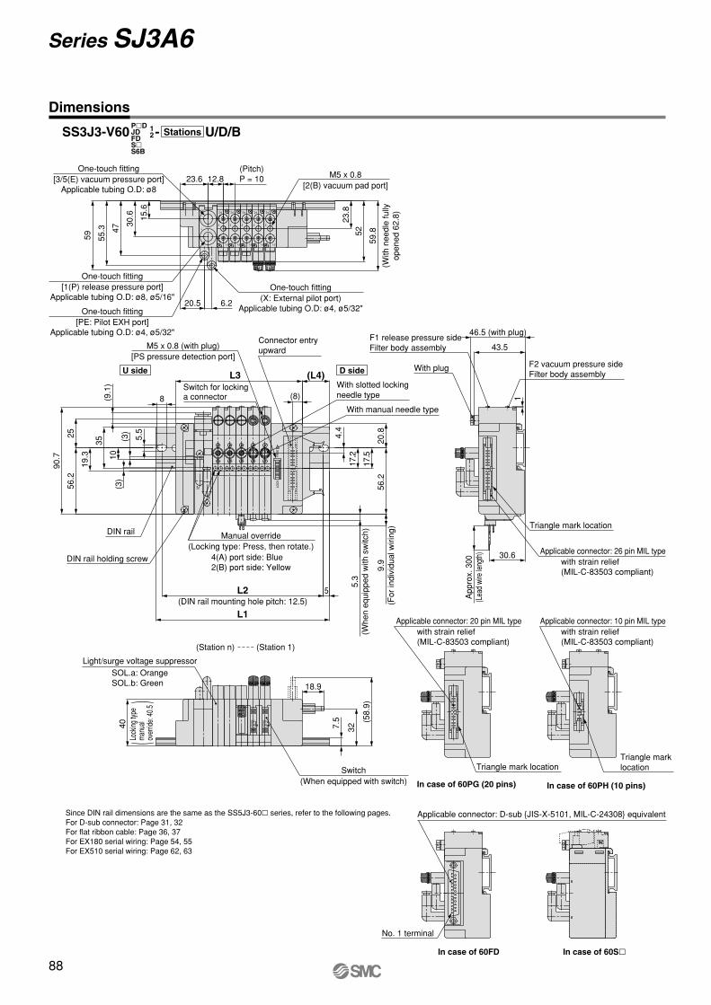
Dimensions
Series SJ3A6
SS3J3-V60 - U/D/BP�DJDFDS�S6B
12 Stations
59.8
(Pitch)P = 10
One-touch fitting[3/5(E) vacuum pressure port]
Applicable tubing O.D: ø8
M5 x 0.8[2(B) vacuum pad port]
One-touch fitting[1(P) release pressure port]
Applicable tubing O.D: ø8, ø5/16"
One-touch fitting[PE: Pilot EXH port]
Applicable tubing O.D: ø4, ø5/32"
One-touch fitting(X: External pilot port)
Applicable tubing O.D: ø4, ø5/32"
(With
nee
dle
fully
open
ed 6
2.8)
L3 (L4)
5.3
(Whe
n eq
uipp
ed w
ith s
witc
h)
9.9
(For
indi
vidu
al w
iring
)
L2
L1
M5 x 0.8 (with plug)[PS pressure detection port]
Connector entry upward
Switch for locking a connector
DIN rail
DIN rail holding screw
(DIN rail mounting hole pitch: 12.5)
With manual needle type
With slotted locking needle type
U side D side
4(A) port side: Blue2(B) port side: Yellow
Manual override(Locking type: Press, then rotate.)
F1 release pressure side Filter body assembly
With plug
46.5 (with plug)
F2 vacuum pressure side Filter body assembly
App
rox.
300
(Lea
d wi
re le
ngth
)
Triangle mark location
Applicable connector: 26 pin MIL type with strain relief (MIL-C-83503 compliant)
(Station 1)(Station n)
40
Light/surge voltage suppressor
Switch(When equipped with switch)
SOL.a: OrangeSOL.b: Green
(
)Lo
cking
type
man
ual
over
ride:
40.
5
Applicable connector: 20 pin MIL type with strain relief (MIL-C-83503 compliant)
Applicable connector: 10 pin MIL type with strain relief (MIL-C-83503 compliant)
Triangle mark location
In case of 60PG (20 pins)
Triangle mark location
In case of 60PH (10 pins)
No. 1 terminal
In case of 60FD
Applicable connector: D-sub {JIS-X-5101, MIL-C-24308} equivalent
In case of 60S�
Since DIN rail dimensions are the same as the SS5J3-60� series, refer to the following pages. For D-sub connector: Page 31, 32For flat ribbon cable: Page 36, 37For EX180 serial wiring: Page 54, 55For EX510 serial wiring: Page 62, 63
P0011-P0100-E.qxd 08.9.1 1:54 PM Page 88
89
SJ
SY
SV
SYJ
SZ
VP4
S0700
VQ
VQ4
VQ5
VQC
VQZ
SQ
VFS
VFR
VQ7
P0011-P0100-E.qxd 08.9.1 1:54 PM Page 89
60 USS3J3 05V
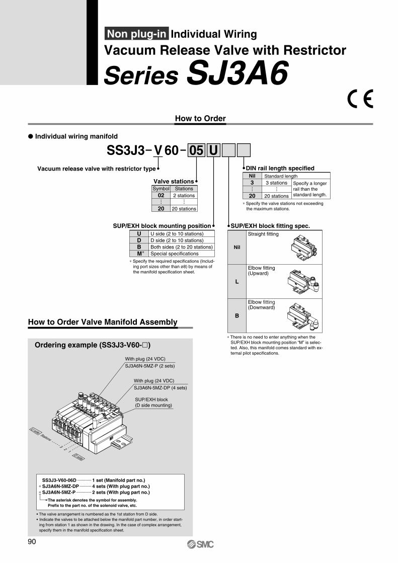
90
Series SJ3A6Vacuum Release Valve with Restrictor
Individual WiringNon plug-in
� Individual wiring manifold
How to Order
Vacuum release valve with restrictor type
∗ Specify the required specifications (Includ-ing port sizes other than ø8) by means of the manifold specification sheet.
SUP/EXH block mounting positionUDBM∗
U side (2 to 10 stations)D side (2 to 10 stations)Both sides (2 to 20 stations)Special specifications
Valve stations
2 stations
20 stations
Symbol Stations02
20
DIN rail length specified
Specify a longer rail than the standard length.
Standard length3 stations
20 stations
Nil3
20
SUP/EXH block fitting spec.
Nil
Straight fitting
L
Elbow fitting(Upward)
B
Elbow fitting(Downward)
∗ There is no need to enter anything when the SUP/EXH block mounting position “M” is selec-ted. Also, this manifold comes standard with ex-ternal pilot specifications.
∗ Specify the valve stations not exceeding the maximum stations.
How to Order Valve Manifold Assembly
Ordering example (SS3J3-V60-�)
With plug (24 VDC)
SJ3A6N-5MZ-P (2 sets)
With plug (24 VDC)
SJ3A6N-5MZ-DP (4 sets)
SUP/EXH block (D side mounting)
13
2
D side
U sideStations
The asterisk denotes the symbol for assembly. Prefix to the part no. of the solenoid valve, etc.
SS3J3-V60-06D 1 set (Manifold part no.)∗ SJ3A6N-5MZ-DP 4 sets (With plug part no.)∗ SJ3A6N-5MZ-P 2 sets (With plug part no.)
• The valve arrangement is numbered as the 1st station from D side. • Indicate the valves to be attached below the manifold part number, in order start-
ing from station 1 as shown in the drawing. In the case of complex arrangement, specify them in the manifold specification sheet.
P0011-P0100-E.qxd 08.9.1 1:54 PM Page 90
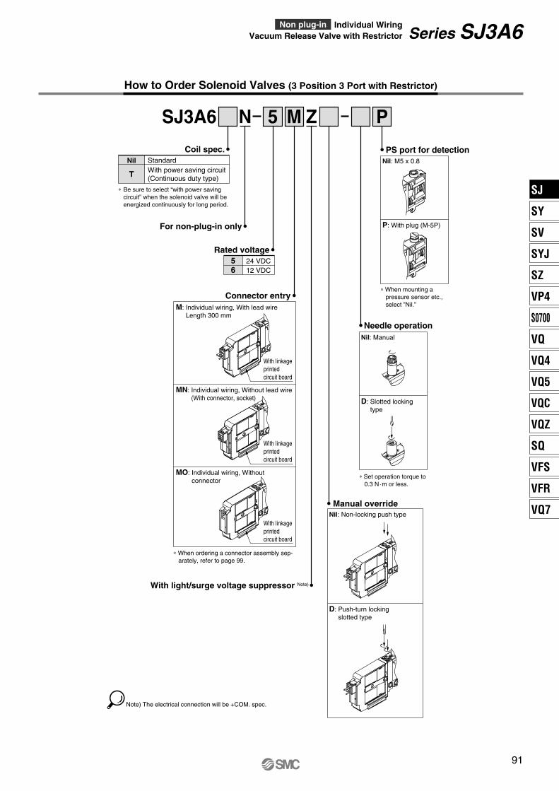
SJ3A6 N 5 PM Z
91
How to Order Solenoid Valves (3 Position 3 Port with Restrictor)
Series SJ3A6Vacuum Release Valve with RestrictorIndividual WiringNon plug-in
Rated voltage24 VDC12 VDC
56
With light/surge voltage suppressor Note)
For non-plug-in only
Needle operation Nil: Manual
D: Slotted lockingtype
PS port for detectionNil: M5 x 0.8
P: With plug (M-5P)
∗ When mounting a pressure sensor etc., select ”Nil.”
Manual overrideNil: Non-locking push type
D: Push-turn locking slotted type
∗ When ordering a connector assembly sep-arately, refer to page 99.
Connector entryM: Individual wiring, With lead wire
Length 300 mm
MN: Individual wiring, Without lead wire(With connector, socket)
MO: Individual wiring, Without connector
With linkage printed circuit board
With linkage printed circuit board
With linkage printed circuit board
∗ Set operation torque to 0.3 N·m or less.
Note) The electrical connection will be +COM. spec.
Coil spec.StandardWith power saving circuit (Continuous duty type)
Nil
T
∗ Be sure to select “with power saving circuit” when the solenoid valve will be energized continuously for long period.
SJ
SY
SV
SYJ
SZ
VP4
S0700
VQ
VQ4
VQ5
VQC
VQZ
SQ
VFS
VFR
VQ7
P0011-P0100-E.qxd 08.9.1 1:54 PM Page 91
43.5
1
30.6
7.5
3/5
12
F1
F2
2
F1
F2
2
F1
F2
2
F1
F2
2
F1
F2
46.2
54.5
58.2 52
23.8
20.5 6.2
12.8
15.6
23.6
30.6
BA BA BABA
PE
X
BA
(9.1
)
90.7
19.3 10
(3)
(3)
56.2
25
9.9
5
20.8
56.2
17.2
8
35
5.5
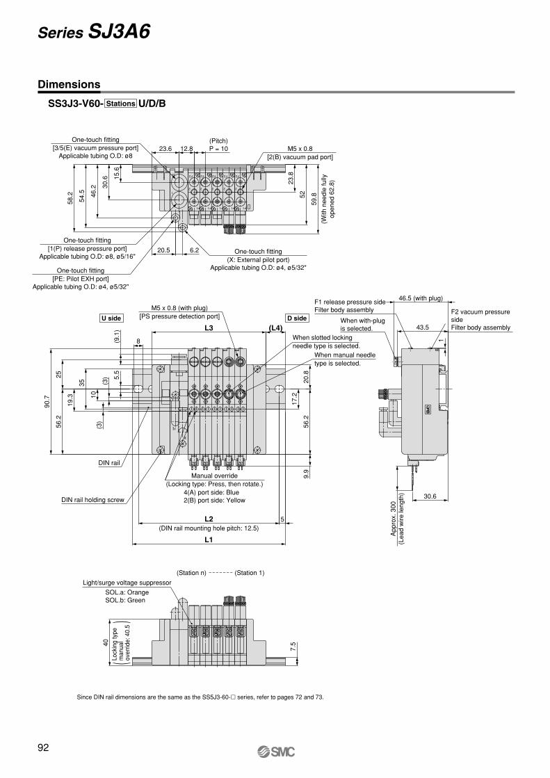
92
Dimensions
Series SJ3A6
SS3J3-V60- U/D/BStations
(With
nee
dle
fully
open
ed 6
2.8)
59.8
One-touch fitting[3/5(E) vacuum pressure port]
Applicable tubing O.D: ø8
(Pitch)P = 10 M5 x 0.8
[2(B) vacuum pad port]
One-touch fitting[1(P) release pressure port]
Applicable tubing O.D: ø8, ø5/16"
One-touch fitting[PE: Pilot EXH port]
Applicable tubing O.D: ø4, ø5/32"
One-touch fitting(X: External pilot port)
Applicable tubing O.D: ø4, ø5/32"
F1 release pressure side Filter body assembly F2 vacuum pressure
side Filter body assembly
When with-plug is selected.
46.5 (with plug)
App
rox.
300
(Lea
d w
ire le
ngth
)
When manual needle type is selected.
When slotted lockingneedle type is selected.
(L4)L3
L1
L2
M5 x 0.8 (with plug)[PS pressure detection port]
DIN rail
DIN rail holding screw
(DIN rail mounting hole pitch: 12.5)
U side D side
4(A) port side: Blue2(B) port side: Yellow
Manual override(Locking type: Press, then rotate.)
(Station 1)(Station n)
40
Light/surge voltage suppressor
Since DIN rail dimensions are the same as the SS5J3-60-� series, refer to pages 72 and 73.
SOL.a: OrangeSOL.b: Green
(
)
Lock
ing
type
man
ual
over
ride:
40.
5
P0011-P0100-E.qxd 08.9.1 1:54 PM Page 92
Connector Block Assembly Part No.
For D-sub connectorFor flat ribbon cable 26 pinsFor flat ribbon cable 20 pinsFor flat ribbon cable 10 pinsFor PC wiring 20 pinsFor EX180 serial wiring Note)
For EX510 serial wiring Note)
For PC wiring 20 pins with power supply terminal
D side
SJ3000-42-1A-�SJ3000-42-2A-�SJ3000-42-3A-�SJ3000-42-4A-�SJ3000-42-6A-�SJ3000-42-5ASJ3000-42-3A-2
SJ3000-76-2A-05
�: 1 (Connector upward)
�: 2 (Connector lateral)
NoteConnector specifications Mounting position Part no.
Note) SI unit is not included.
w
q
r
e
t
e
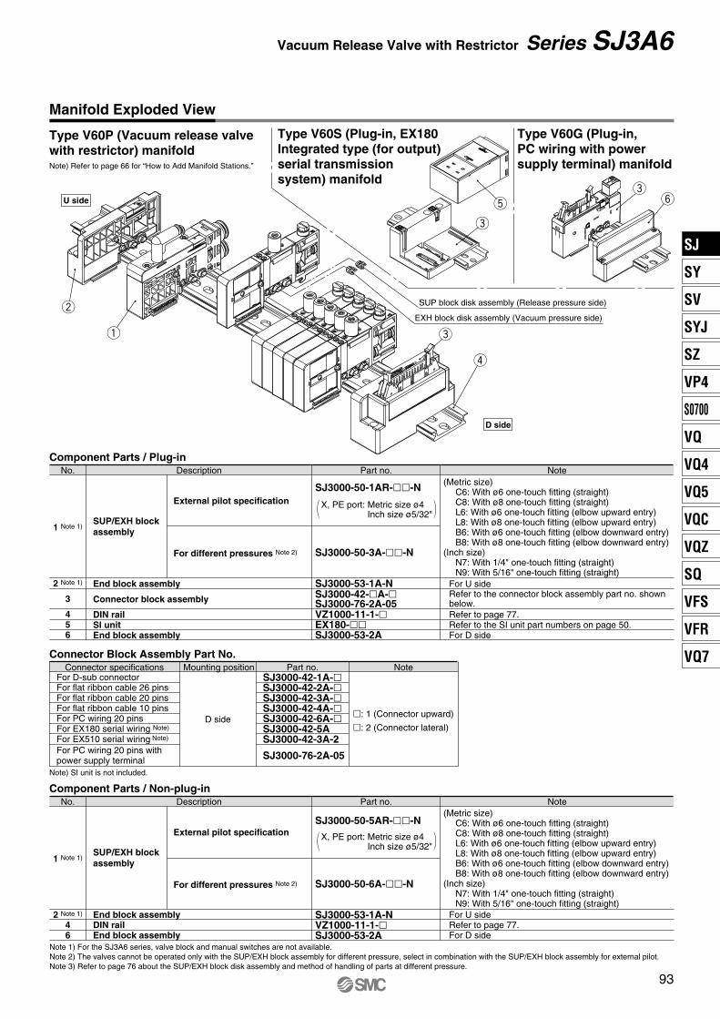
Note) Refer to page 66 for “How to Add Manifold Stations.”
Type V60G (Plug-in, PC wiring with power supply terminal) manifold
ey
Type V60P (Vacuum release valve with restrictor) manifold
Type V60S (Plug-in, EX180 Integrated type (for output) serial transmission system) manifold
93
Manifold Exploded View
Vacuum Release Valve with Restrictor Series SJ3A6
SUP block disk assembly (Release pressure side)
EXH block disk assembly (Vacuum pressure side)
U side
D side
Component Parts / Plug-in
1 Note 1)
2 Note 1)
3
456
SUP/EXH block assembly
End block assembly
Connector block assembly
DIN railSI unitEnd block assembly
External pilot specification
For different pressures Note 2)
SJ3000-50-1AR-��-N
SJ3000-50-3A-��-N
SJ3000-53-1A-N
VZ1000-11-1-�EX180-��SJ3000-53-2A
SJ3000-42-�A-�SJ3000-76-2A-05
NotePart no.DescriptionNo.
For U side
Refer to page 77.Refer to the SI unit part numbers on page 50.For D side
Refer to the connector block assembly part no. shown below.
X, PE port: Metric size ø4Inch size ø5/32"
(Metric size)C6: With ø6 one-touch fitting (straight)C8: With ø8 one-touch fitting (straight)L6: With ø6 one-touch fitting (elbow upward entry)L8: With ø8 one-touch fitting (elbow upward entry)B6: With ø6 one-touch fitting (elbow downward entry)B8: With ø8 one-touch fitting (elbow downward entry)
(Inch size)N7: With 1/4" one-touch fitting (straight)N9: With 5/16" one-touch fitting (straight)
Component Parts / Non-plug-in
SUP/EXH block assembly
End block assemblyDIN railEnd block assembly
External pilot specification
For different pressures Note 2)
SJ3000-50-5AR-��-N
SJ3000-50-6A-��-N
SJ3000-53-1A-NVZ1000-11-1-�SJ3000-53-2A
For U sideRefer to page 77.For D side
NotePart no.DescriptionNo.
X, PE port: Metric size ø4Inch size ø5/32"
(Metric size)C6: With ø6 one-touch fitting (straight)C8: With ø8 one-touch fitting (straight)L6: With ø6 one-touch fitting (elbow upward entry)L8: With ø8 one-touch fitting (elbow upward entry)B6: With ø6 one-touch fitting (elbow downward entry)B8: With ø8 one-touch fitting (elbow downward entry)
(Inch size)N7: With 1/4" one-touch fitting (straight)N9: With 5/16" one-touch fitting (straight)
1 Note 1)
2 Note 1)
46
Note 1) For the SJ3A6 series, valve block and manual switches are not available.Note 2) The valves cannot be operated only with the SUP/EXH block assembly for different pressure, select in combination with the SUP/EXH block assembly for external pilot.Note 3) Refer to page 76 about the SUP/EXH block disk assembly and method of handling of parts at different pressure.
SJ
SY
SV
SYJ
SZ
VP4
S0700
VQ
VQ4
VQ5
VQC
VQZ
SQ
VFS
VFR
VQ7
P0011-P0100-E.qxd 08.9.1 1:54 PM Page 93
ONOFF
OFFON
94
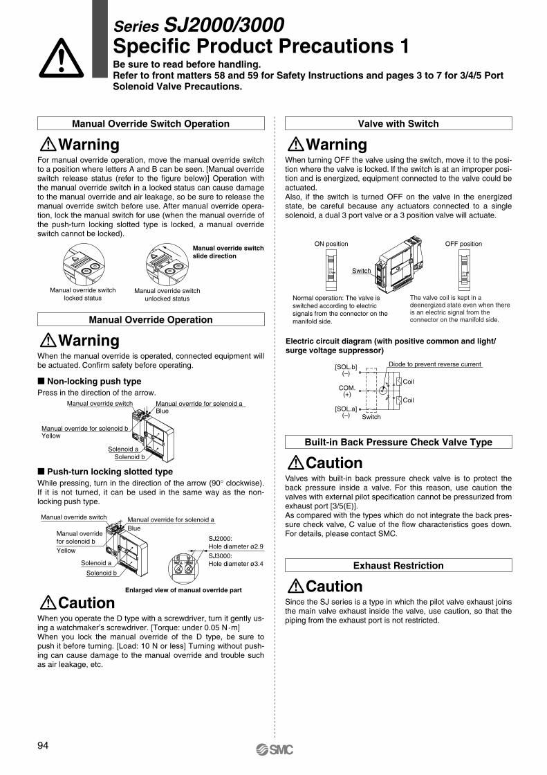
Series SJ2000/3000Specific Product Precautions 1Be sure to read before handling.Refer to front matters 58 and 59 for Safety Instructions and pages 3 to 7 for 3/4/5 Port Solenoid Valve Precautions.
For manual override operation, move the manual override switch to a position where letters A and B can be seen. [Manual override switch release status (refer to the figure below)] Operation with the manual override switch in a locked status can cause damage to the manual override and air leakage, so be sure to release the manual override switch before use. After manual override opera-tion, lock the manual switch for use (when the manual override of the push-turn locking slotted type is locked, a manual override switch cannot be locked).
WarningManual Override Switch Operation
Manual override switch slide direction
Manual override switchlocked status
Manual override switchunlocked status
� Non-locking push typePress in the direction of the arrow.
When the manual override is operated, connected equipment will be actuated. Confirm safety before operating.
WarningManual Override Operation
Solenoid bSolenoid a
Manual override for solenoid bYellow
Manual override for solenoid aBlue
Manual override switch
� Push-turn locking slotted typeWhile pressing, turn in the direction of the arrow (90° clockwise). If it is not turned, it can be used in the same way as the non-locking push type.
Solenoid b
Solenoid a
Manual override switch
Manual override for solenoid bYellow
Manual override for solenoid aBlue
SJ2000:Hole diameter ø2.9
SJ3000:Hole diameter ø3.4
Enlarged view of manual override part
When you operate the D type with a screwdriver, turn it gently us-ing a watchmaker’s screwdriver. [Torque: under 0.05 N·m]When you lock the manual override of the D type, be sure to push it before turning. [Load: 10 N or less] Turning without push-ing can cause damage to the manual override and trouble such as air leakage, etc.
Caution
When turning OFF the valve using the switch, move it to the posi-tion where the valve is locked. If the switch is at an improper posi-tion and is energized, equipment connected to the valve could be actuated.Also, if the switch is turned OFF on the valve in the energized state, be careful because any actuators connected to a single solenoid, a dual 3 port valve or a 3 position valve will actuate.
WarningValve with Switch
ON position
Switch
OFF position
Normal operation: The valve is switched according to electric signals from the connector on the manifold side.
The valve coil is kept in a deenergized state even when there is an electric signal from the connector on the manifold side.
Since the SJ series is a type in which the pilot valve exhaust joins the main valve exhaust inside the valve, use caution, so that the piping from the exhaust port is not restricted.
CautionExhaust Restriction
Diode to prevent reverse current
Switch
Coil
Coil
(–)[SOL.a]
(+)COM.
(–)[SOL.b]
Electric circuit diagram (with positive common and light/surge voltage suppressor)
Valves with built-in back pressure check valve is to protect the back pressure inside a valve. For this reason, use caution the valves with external pilot specification cannot be pressurized from exhaust port [3/5(E)].As compared with the types which do not integrate the back pres-sure check valve, C value of the flow characteristics goes down. For details, please contact SMC.
CautionBuilt-in Back Pressure Check Valve Type
P0011-P0100-E.qxd 08.9.1 1:54 PM Page 94
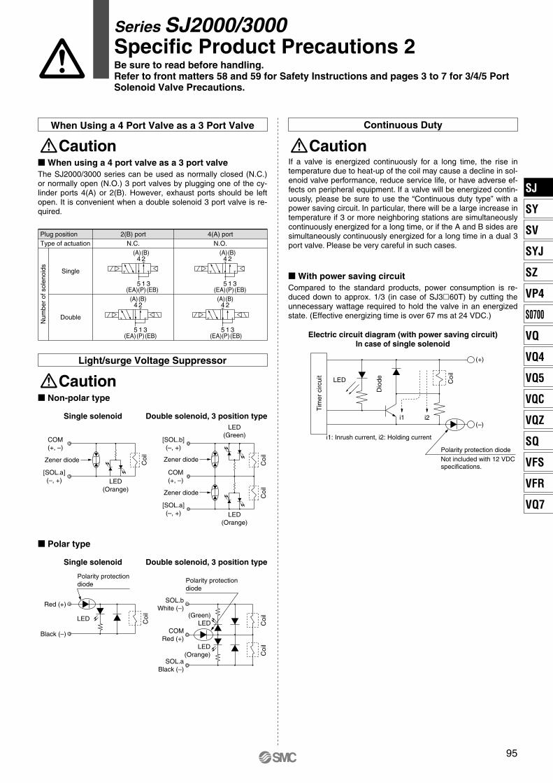
When Using a 4 Port Valve as a 3 Port Valve
Plug position 2(B) portN.C.
4(A) portN.O.Type of actuation
Double
Num
ber
of s
olen
oids
2(B)
4(A)
(EB)(P)(EA)5 1 3
(A)4 2
(B)
315(EA)(P)(EB)
(A)4 2
(B)
315(EA)(P)(EB)(A)
4 2(B)
315(EA)(P)(EB)
Single
95
� When using a 4 port valve as a 3 port valveThe SJ2000/3000 series can be used as normally closed (N.C.) or normally open (N.O.) 3 port valves by plugging one of the cy-linder ports 4(A) or 2(B). However, exhaust ports should be left open. It is convenient when a double solenoid 3 port valve is re-quired.
Caution
� Non-polar type
CautionLight/surge Voltage Suppressor
Single solenoid Double solenoid, 3 position type
Zener diode
[SOL.a](–, +)
COM(+, –)
LED(Orange)
Zener diode
Zener diode
[SOL.a](–, +)
COM(+, –)
[SOL.b](–, +)
LED(Green)
LED(Orange)
Coi
l
Coi
lC
oil
Single solenoid Double solenoid, 3 position type
Red (+)
Black (–)
Polarity protectiondiode
LED
SOL.bWhite (–)
COMRed (+)
SOL.aBlack (–)
Polarity protectiondiode
(Green)LED
LED(Orange)
� Polar type
Coi
l
Coi
lC
oil
� With power saving circuitCompared to the standard products, power consumption is re-duced down to approx. 1/3 (in case of SJ3�60T) by cutting the unnecessary wattage required to hold the valve in an energized state. (Effective energizing time is over 67 ms at 24 VDC.)
If a valve is energized continuously for a long time, the rise in temperature due to heat-up of the coil may cause a decline in sol-enoid valve performance, reduce service life, or have adverse ef-fects on peripheral equipment. If a valve will be energized contin-uously, please be sure to use the “Continuous duty type” with a power saving circuit. In particular, there will be a large increase in temperature if 3 or more neighboring stations are simultaneously continuously energized for a long time, or if the A and B sides are simultaneously continuously energized for a long time in a dual 3 port valve. Please be very careful in such cases.
Continuous Duty
Electric circuit diagram (with power saving circuit)In case of single solenoid
i1: Inrush current, i2: Holding current
i2i1(–)
(+)
LED
Polarity protection diodeNot included with 12 VDC specifications.
Caution
Coi
l
Dio
de
Tim
er c
ircui
t
Series SJ2000/3000Specific Product Precautions 2Be sure to read before handling.Refer to front matters 58 and 59 for Safety Instructions and pages 3 to 7 for 3/4/5 Port Solenoid Valve Precautions.
SJ
SY
SV
SYJ
SZ
VP4
S0700
VQ
VQ4
VQ5
VQC
VQZ
SQ
VFS
VFR
VQ7
P0011-P0100-E.qxd 08.9.1 1:54 PM Page 95
96
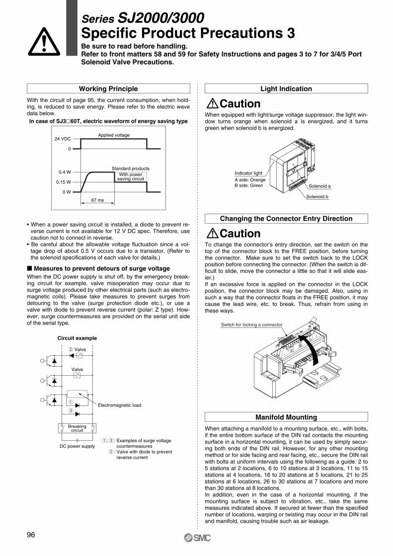
When equipped with light/surge voltage suppressor, the light win-dow turns orange when solenoid a is energized, and it turns green when solenoid b is energized.
CautionLight Indication
To change the connector’s entry direction, set the switch on the top of the connector block to the FREE position, before turning the connector. Make sure to set the switch back to the LOCK position before connecting the connector. (When the switch is dif-ficult to slide, move the connector a little so that it will slide eas-ier.)If an excessive force is applied on the connector in the LOCK position, the connector block may be damaged. Also, using in such a way that the connector floats in the FREE position, it may cause the lead wire, etc. to break. Thus, refrain from using in these ways.
CautionChanging the Connector Entry Direction
When attaching a manifold to a mounting surface, etc., with bolts, if the entire bottom surface of the DIN rail contacts the mounting surface in a horizontal mounting, it can be used by simply secur-ing both ends of the DIN rail. However, for any other mounting method or for side facing and rear facing, etc., secure the DIN rail with bolts at uniform intervals using the following as a guide: 2 to 5 stations at 2 locations, 6 to 10 stations at 3 locations, 11 to 15 stations at 4 locations, 16 to 20 stations at 5 locations, 21 to 25 stations at 6 locations, 26 to 30 stations at 7 locations and more than 30 stations at 8 locations.In addition, even in the case of a horizontal mounting, if the mounting surface is subject to vibration, etc., take the same measures indicated above. If secured at fewer than the specified number of locations, warping or twisting may occur in the DIN rail and manifold, causing trouble such as air leakage.
Manifold Mounting
Switch for locking a connector
Indicator light
A side: OrangeB side: Green
Solenoid b
Solenoid a
LOCK
FREE
• When a power saving circuit is installed, a diode to prevent re-verse current is not available for 12 V DC spec. Therefore, use caution not to connect in reverse.
• Be careful about the allowable voltage fluctuation since a vol-tage drop of about 0.5 V occurs due to a transistor. (Refer to the solenoid specifications of each valve for details.)
With the circuit of page 95, the current consumption, when hold-ing, is reduced to save energy. Please refer to the electric wave data below.
Working Principle
67 ms
With powersaving circuit
0 W
0
Standard products
0.15 W
0.4 W
24 VDCApplied voltage
In case of SJ3�60T, electric waveform of energy saving type
� Measures to prevent detours of surge voltageWhen the DC power supply is shut off, by the emergency break-ing circuit for example, valve misoperation may occur due to surge voltage produced by other electrical parts (such as electro-magnetic coils). Please take measures to prevent surges from detouring to the valve (surge protection diode etc.), or use a valve with diode to prevent reverse current (polar: Z type). How-ever, surge countermeasures are provided on the serial unit side of the serial type.
DC power supply
Breakingcircuit
e
q
Valve
Electromagnetic load
w Valve
Circuit example
q,e : Examples of surge voltage countermeasures
w : Valve with diode to preventreverse current
Series SJ2000/3000Specific Product Precautions 3Be sure to read before handling.Refer to front matters 58 and 59 for Safety Instructions and pages 3 to 7 for 3/4/5 Port Solenoid Valve Precautions.
P0011-P0100-E.qxd 08.9.1 1:54 PM Page 96
97
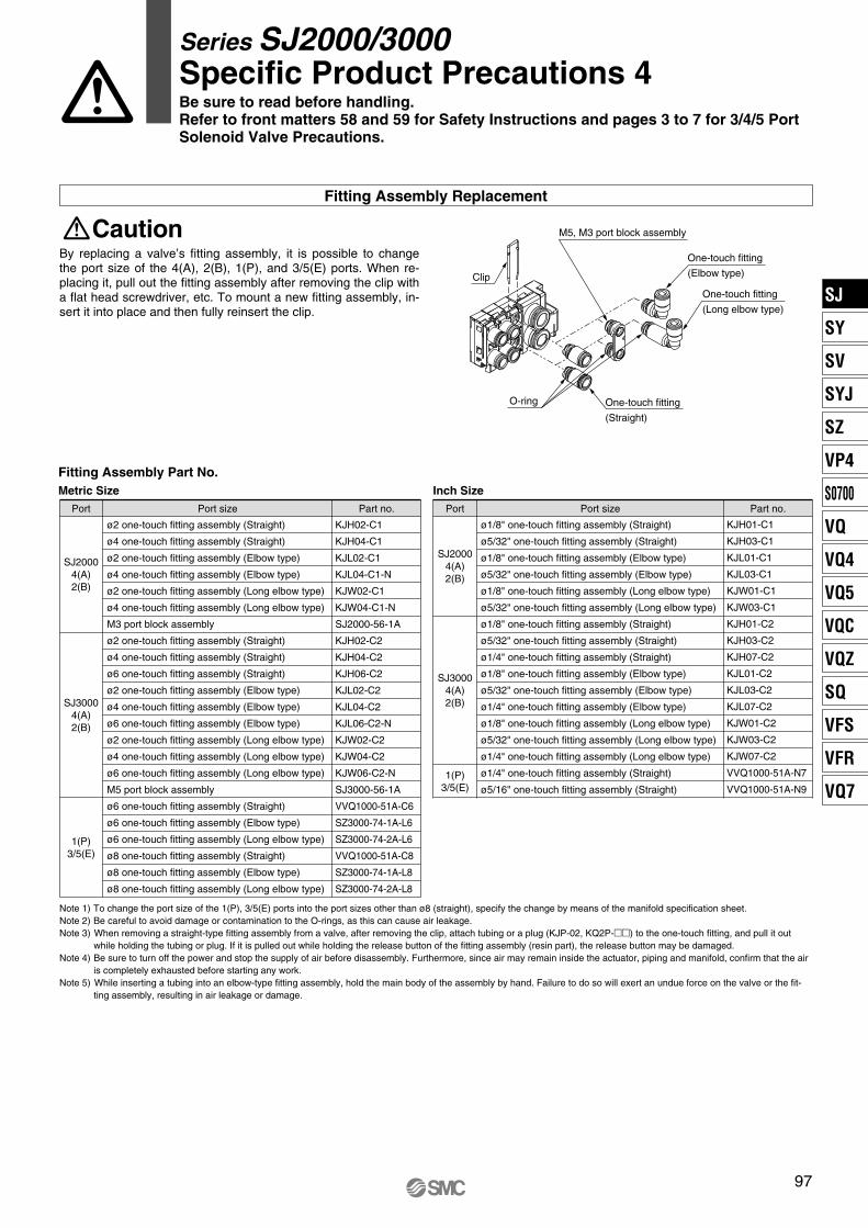
By replacing a valve’s fitting assembly, it is possible to change the port size of the 4(A), 2(B), 1(P), and 3/5(E) ports. When re-placing it, pull out the fitting assembly after removing the clip with a flat head screwdriver, etc. To mount a new fitting assembly, in-sert it into place and then fully reinsert the clip.
Note 1) To change the port size of the 1(P), 3/5(E) ports into the port sizes other than ø8 (straight), specify the change by means of the manifold specification sheet.Note 2) Be careful to avoid damage or contamination to the O-rings, as this can cause air leakage.Note 3) When removing a straight-type fitting assembly from a valve, after removing the clip, attach tubing or a plug (KJP-02, KQ2P-��) to the one-touch fitting, and pull it out
while holding the tubing or plug. If it is pulled out while holding the release button of the fitting assembly (resin part), the release button may be damaged.Note 4) Be sure to turn off the power and stop the supply of air before disassembly. Furthermore, since air may remain inside the actuator, piping and manifold, confirm that the air
is completely exhausted before starting any work.Note 5) While inserting a tubing into an elbow-type fitting assembly, hold the main body of the assembly by hand. Failure to do so will exert an undue force on the valve or the fit-
ting assembly, resulting in air leakage or damage.
CautionFitting Assembly Replacement
ø2 one-touch fitting assembly (Straight)
ø4 one-touch fitting assembly (Straight)
ø2 one-touch fitting assembly (Elbow type)
ø4 one-touch fitting assembly (Elbow type)
ø2 one-touch fitting assembly (Long elbow type)
ø4 one-touch fitting assembly (Long elbow type)
M3 port block assembly
ø2 one-touch fitting assembly (Straight)
ø4 one-touch fitting assembly (Straight)
ø6 one-touch fitting assembly (Straight)
ø2 one-touch fitting assembly (Elbow type)
ø4 one-touch fitting assembly (Elbow type)
ø6 one-touch fitting assembly (Elbow type)
ø2 one-touch fitting assembly (Long elbow type)
ø4 one-touch fitting assembly (Long elbow type)
ø6 one-touch fitting assembly (Long elbow type)
M5 port block assembly
ø6 one-touch fitting assembly (Straight)
ø6 one-touch fitting assembly (Elbow type)
ø6 one-touch fitting assembly (Long elbow type)
ø8 one-touch fitting assembly (Straight)
ø8 one-touch fitting assembly (Elbow type)
ø8 one-touch fitting assembly (Long elbow type)
Port Port size
KJH02-C1
KJH04-C1
KJL02-C1
KJL04-C1-N
KJW02-C1
KJW04-C1-N
SJ2000-56-1A
KJH02-C2
KJH04-C2
KJH06-C2
KJL02-C2
KJL04-C2
KJL06-C2-N
KJW02-C2
KJW04-C2
KJW06-C2-N
SJ3000-56-1A
VVQ1000-51A-C6
SZ3000-74-1A-L6
SZ3000-74-2A-L6
VVQ1000-51A-C8
SZ3000-74-1A-L8
SZ3000-74-2A-L8
Part no.
SJ20004(A)2(B)
SJ30004(A)2(B)
1(P)3/5(E)
ø1/8" one-touch fitting assembly (Straight)
ø5/32" one-touch fitting assembly (Straight)
ø1/8" one-touch fitting assembly (Elbow type)
ø5/32" one-touch fitting assembly (Elbow type)
ø1/8" one-touch fitting assembly (Long elbow type)
ø5/32" one-touch fitting assembly (Long elbow type)
ø1/8" one-touch fitting assembly (Straight)
ø5/32" one-touch fitting assembly (Straight)
ø1/4" one-touch fitting assembly (Straight)
ø1/8" one-touch fitting assembly (Elbow type)
ø5/32" one-touch fitting assembly (Elbow type)
ø1/4" one-touch fitting assembly (Elbow type)
ø1/8" one-touch fitting assembly (Long elbow type)
ø5/32" one-touch fitting assembly (Long elbow type)
ø1/4" one-touch fitting assembly (Long elbow type)
ø1/4" one-touch fitting assembly (Straight)
ø5/16" one-touch fitting assembly (Straight)
Port Port size
KJH01-C1
KJH03-C1
KJL01-C1
KJL03-C1
KJW01-C1
KJW03-C1
KJH01-C2
KJH03-C2
KJH07-C2
KJL01-C2
KJL03-C2
KJL07-C2
KJW01-C2
KJW03-C2
KJW07-C2
VVQ1000-51A-N7
VVQ1000-51A-N9
Part no.
SJ20004(A)2(B)
SJ30004(A)2(B)
1(P)3/5(E)
One-touch fitting
(Straight)
M5, M3 port block assembly
One-touch fitting
(Elbow type)
One-touch fitting
(Long elbow type)
O-ring
Clip
Fitting Assembly Part No.Metric Size Inch Size
Series SJ2000/3000Specific Product Precautions 4Be sure to read before handling.Refer to front matters 58 and 59 for Safety Instructions and pages 3 to 7 for 3/4/5 Port Solenoid Valve Precautions.
SJ
SY
SV
SYJ
SZ
VP4
S0700
VQ
VQ4
VQ5
VQC
VQZ
SQ
VFS
VFR
VQ7
P0011-P0100-E.qxd 08.9.1 1:54 PM Page 97
98
3/5(E) port
1(P) port
4(A) port 2(B) port
Hold down part of the release bush with your finger or a similar tool, as shown in the diagram, and pull out in the direction indicated by the arrow.
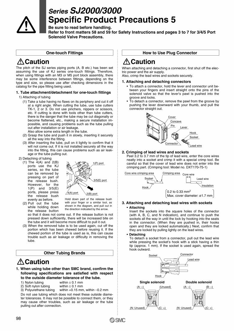
When attaching and detaching a connector, first shut off the elec-tric power and the air supply. Also, crimp the lead wires and sockets securely.
1. Attaching and detaching connectors• To attach a connector, hold the lever and connector unit be-
tween your fingers and insert straight onto the pins of the solenoid valve so that the lever’s pawl is pushed into the groove and locks.
• To detach a connector, remove the pawl from the groove by pushing the lever downward with your thumb, and pull the connector straight out.
2. Crimping of lead wires and socketsPeel 3.2 to 3.7 mm of the tip of lead wire, enter the core wires neatly into a socket and crimp it with a special crimp tool. Be careful so that the cover of lead wire does not enter into the crimping part. (Crimping tool: Model no. DXT170-75-1)
3. Attaching and detaching lead wires with sockets• Attaching
Insert the sockets into the square holes of the connector (with A, B, C, and N indication), and continue to push the sockets all the way in until the lock by hooking into the seats in the connector. (When they are pushed in, their hooks open and they are locked automatically.) Next, confirm that they are locked by pulling lightly on the lead wires.
• DetachingTo detach a socket from a connector, pull out the lead wire while pressing the socket’s hook with a stick having a thin tip (approx. 1 mm). If the socket is used again, spread the hook outward.
CautionHow to Use Plug Connector
Single solenoid Double solenoid
0.2 to 0.33 mm2
Max. cover diameter: ø1.7 mm
Core wireCrimping areaCore wire crimping area
InsulationHook
Lead wireSocket
Hook
Socket Connector
Lead wire
Lead wire
Socket
Hook
Pin
Concave
Connector
Lever
Cover
(C: +)
(B: –)(A: –)
(N: Unused)
(A: –) (Unused)
(C: +)(N: Unused)
CautionOne-touch Fittings
1. When using tube other than SMC brand, confirm the following specifications are satisfied with respect to the outside diameter tolerance of the tube.1) Nylon tubing within ± 0.1 mm2) Soft nylon tubing within ± 0.1 mm3) Polyurethane tubing within +0.15 mm, within –0.2 mmDo not use tubing which does not meet these outside diame-ter tolerances. It may not be possible to connect them, or they may cause other troubles, such as air leakage or the tube pulling out after connection.
CautionOther Tubing Brands
The pitch of the SJ series piping ports (A, B etc.) has been set assuming the use of KJ series one-touch fittings. Therefore, when using fittings with an M3 or M5 port block assembly, there may be some interference between fittings, depending on the type and size, so please use after checking dimensions in the catalog for the pipe fitting being used.
1. Tube attachment/detachment for one-touch fittings1) Attaching of tubing
(1) Take a tube having no flaws on its periphery and cut it off at a right angle. When cutting the tube, use tube cutters TK-1, 2 or 3. Do not use pinchers, nippers or scissors, etc. If cutting is done with tools other than tube cutters, there is the danger that the tube may be cut diagonally or become flattened, etc., making a secure installation im-possible, and causing problems such as the tube pulling out after installation or air leakage.Also allow some extra length in the tube.
(2) Grasp the tube and push it in slowly, inserting it securely all the way into the fitting.
(3) After inserting the tube, pull on it lightly to confirm that it will not come out. If it is not installed securely all the way into the fitting, this can cause problems such as air leak-age or the tube pulling out.
2) Detaching of tubing(1) The 4(A) and 2(B)
ports use the KJ series, so the tube can be removed by pressing on part of the release bush. However, for the 1(P) and 3/5(E) ports, please press the release bush evenly as before.
(2) Pull out the tube while holding down the release button so that it does not come out. If the release button is not pressed down sufficiently, there will be increased bite on the tube and it will become more difficult to pull it out.
(3) When the removed tube is to be used again, cut off the portion which has been chewed before reusing it. If the chewed portion of the tube is used as is, this can cause trouble such as air leakage or difficulty in removing the tube.
Series SJ2000/3000Specific Product Precautions 5Be sure to read before handling.Refer to front matters 58 and 59 for Safety Instructions and pages 3 to 7 for 3/4/5 Port Solenoid Valve Precautions.
P0011-P0100-E.qxd 08.9.1 1:54 PM Page 98
99
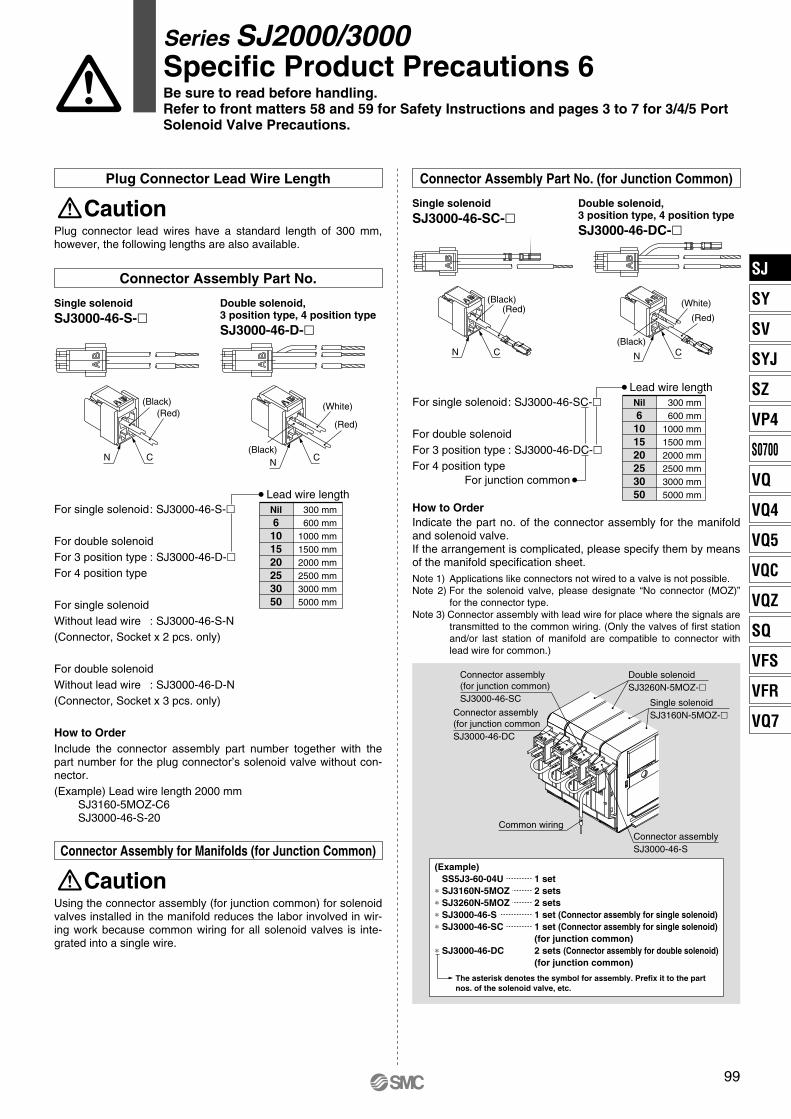
Connector Assembly Part No. (for Junction Common)
Single solenoid
SJ3000-46-SC-�Double solenoid, 3 position type, 4 position type
SJ3000-46-DC-�
For single solenoid: SJ3000-46-SC-�
For double solenoidFor 3 position type : SJ3000-46-DC-�For 4 position type
Lead wire lengthNil6101520253050
300 mm600 mm
1000 mm1500 mm2000 mm2500 mm3000 mm5000 mm
N C
(Red)(Black)
(Black)
(Red)
(White)
CN
The asterisk denotes the symbol for assembly. Prefix it to the part nos. of the solenoid valve, etc.
(Example)SS5J3-60-04U 1 set
∗ SJ3160N-5MOZ 2 sets∗ SJ3260N-5MOZ 2 sets∗ SJ3000-46-S 1 set (Connector assembly for single solenoid)∗ SJ3000-46-SC 1 set (Connector assembly for single solenoid)
(for junction common)∗ SJ3000-46-DC 2 sets (Connector assembly for double solenoid)
(for junction common)
Double solenoidSJ3260N-5MOZ-�
Connector assembly(for junction common)SJ3000-46-SC
Connector assembly(for junction commonSJ3000-46-DC
Common wiringConnector assemblySJ3000-46-S
Single solenoidSJ3160N-5MOZ-�
For junction common
Using the connector assembly (for junction common) for solenoid valves installed in the manifold reduces the labor involved in wir-ing work because common wiring for all solenoid valves is inte-grated into a single wire.
CautionConnector Assembly for Manifolds (for Junction Common)
Plug connector lead wires have a standard length of 300 mm, however, the following lengths are also available.
CautionPlug Connector Lead Wire Length
Connector Assembly Part No.
CN
(Red)(Black)
CN(Black)
(Red)
(White)
Single solenoid
SJ3000-46-S-�Double solenoid, 3 position type, 4 position type
SJ3000-46-D-�
For single solenoid: SJ3000-46-S-�
For double solenoidFor 3 position type : SJ3000-46-D-�For 4 position type
For single solenoidWithout lead wire : SJ3000-46-S-N(Connector, Socket x 2 pcs. only)
For double solenoidWithout lead wire : SJ3000-46-D-N(Connector, Socket x 3 pcs. only)
How to OrderInclude the connector assembly part number together with the part number for the plug connector’s solenoid valve without con-nector.(Example) Lead wire length 2000 mm
SJ3160-5MOZ-C6SJ3000-46-S-20
Lead wire lengthNil6101520253050
300 mm600 mm
1000 mm1500 mm2000 mm2500 mm3000 mm5000 mm
How to OrderIndicate the part no. of the connector assembly for the manifold and solenoid valve. If the arrangement is complicated, please specify them by means of the manifold specification sheet.Note 1) Applications like connectors not wired to a valve is not possible.Note 2) For the solenoid valve, please designate “No connector (MOZ)”
for the connector type.Note 3) Connector assembly with lead wire for place where the signals are
transmitted to the common wiring. (Only the valves of first station and/or last station of manifold are compatible to connector with lead wire for common.)
Series SJ2000/3000Specific Product Precautions 6Be sure to read before handling.Refer to front matters 58 and 59 for Safety Instructions and pages 3 to 7 for 3/4/5 Port Solenoid Valve Precautions.
SJ
SY
SV
SYJ
SZ
VP4
S0700
VQ
VQ4
VQ5
VQC
VQZ
SQ
VFS
VFR
VQ7
P0011-P0100-E.qxd 08.9.1 1:54 PM Page 99
100
Lead wireCompatible lead wire range 0.13 to 2.5 mm2
Wire core
Insert wire core into the square hole
Power supply terminal connector(Detachable)
Terminal screws (2 locations)Tightening torque0.4 to 0.6 N·m
PCW type
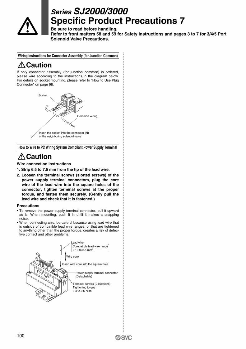
Common wiring
Socket
Insert the socket into the connector (N) of the neighboring solenoid valve
If only connector assembly (for junction common) is ordered, please wire according to the instructions in the diagram below. For details on socket mounting, please refer to "How to Use Plug Connector" on page 98.
CautionWiring Instructions for Connector Assembly (for Junction Common)
Wire connection instructions1. Strip 6.5 to 7.5 mm from the tip of the lead wire. 2. Loosen the terminal screws (slotted screws) of the
power supply terminal connectors, plug the core wire of the lead wire into the square holes of the connector, tighten terminal screws at the proper torque, and fasten them securely. (Gently pull the lead wire and check that it is fastened.)
Precautions• To remove the power supply terminal connector, pull it upward
as is. When mounting, push it in until it makes a snapping noise.
• When connecting wire, be careful because using lead wire that is outside of compatible lead wire ranges, or that are tightened to anything other than the proper torque, creates a risk of defec-tive contact and other problems.
CautionHow to Wire to PC Wiring System Compliant Power Supply Terminal
Series SJ2000/3000Specific Product Precautions 7Be sure to read before handling.Refer to front matters 58 and 59 for Safety Instructions and pages 3 to 7 for 3/4/5 Port Solenoid Valve Precautions.
P0011-P0100-E.qxd 08.9.1 1:54 PM Page 100