Embed Size (px)
Citation preview
619
Compressor
Filter regulator
Solenoid valve forvacuum breaking air
Throttle valve2-way/3-way vacuum valve Vacuum switch
Filter
Vacuum pump Vacuum regulator
Vacuum valve unit
Vacuum padPositivepressure
Negativepressure
A solenoid vacuum valve with additional functions (vacuum break, hold detection, etc.) required for vacuumpad using transfer system control. (As there is no vacuum generation function, be sure to also connect avacuum pump, etc.)
● MV180 Series: Large flow rate type with effective area of 4 mm2 [Cv = 0.22]MV030, MV090 Series: Compact type with effective area of 0.55 mm2 [Cv = 0.0306]and 2 mm2 [Cv = 0.11]
● Lineup of a wide range of applications enables selection suited to the transferworkpiece on the production line in factory.
● Electronic vacuum switch equipped with LED display for easy operations check
The Koganei Vacuum Valve Unit Is...
Single UnitWithout filter and vacuum switchSingle Unit
With filter and vacuum switch
A type manifold, two to eight unitsWithout filter and vacuum switch
AS type manifold, two to eight unitsWith filter and vacuum switch
A type manifold, two to eight unitsSome units with filter and vacuumswitch and some without(only for MV180 series)
Vacuum Valve Units
620
VACU
UM V
ALVE
UNI
TS
A. S. OUT
S.W.OUTch
1234
PSU
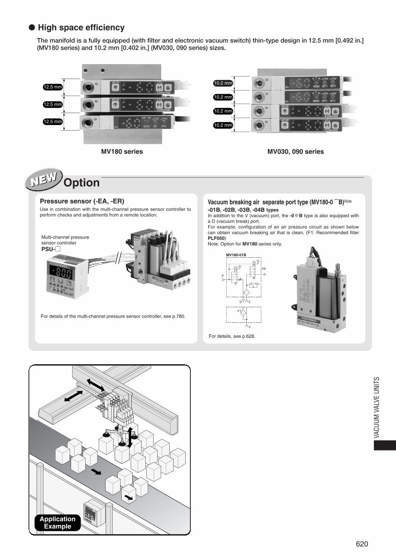
ApplicationExample
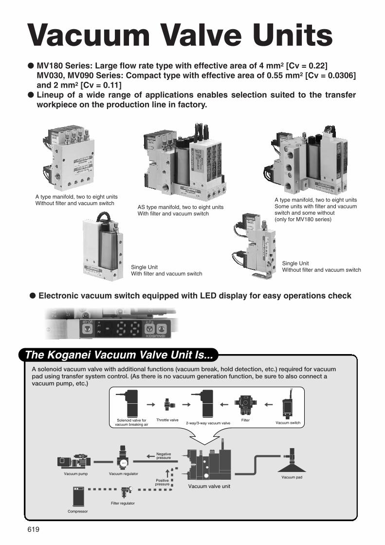
The manifold is a fully equipped (with filter and electronic vacuum switch) thin-type design in 12.5 mm [0.492 in.](MV180 series) and 10.2 mm [0.402 in.] (MV030, 090 series) sizes.
MV180 series MV030, 090 series
● High space efficiency
10.2 mm
10.2 mm
10.2 mm
10.2 mm
12.5 mm
12.5 mm
12.5 mm
Option
For details, see p.628.
For details of the multi-channel pressure sensor controller, see p.780.
Multi-channel pressuresensor controllerPSU-□
Use in combination with the multi-channel pressure sensor controller toperform checks and adjustments from a remote location.
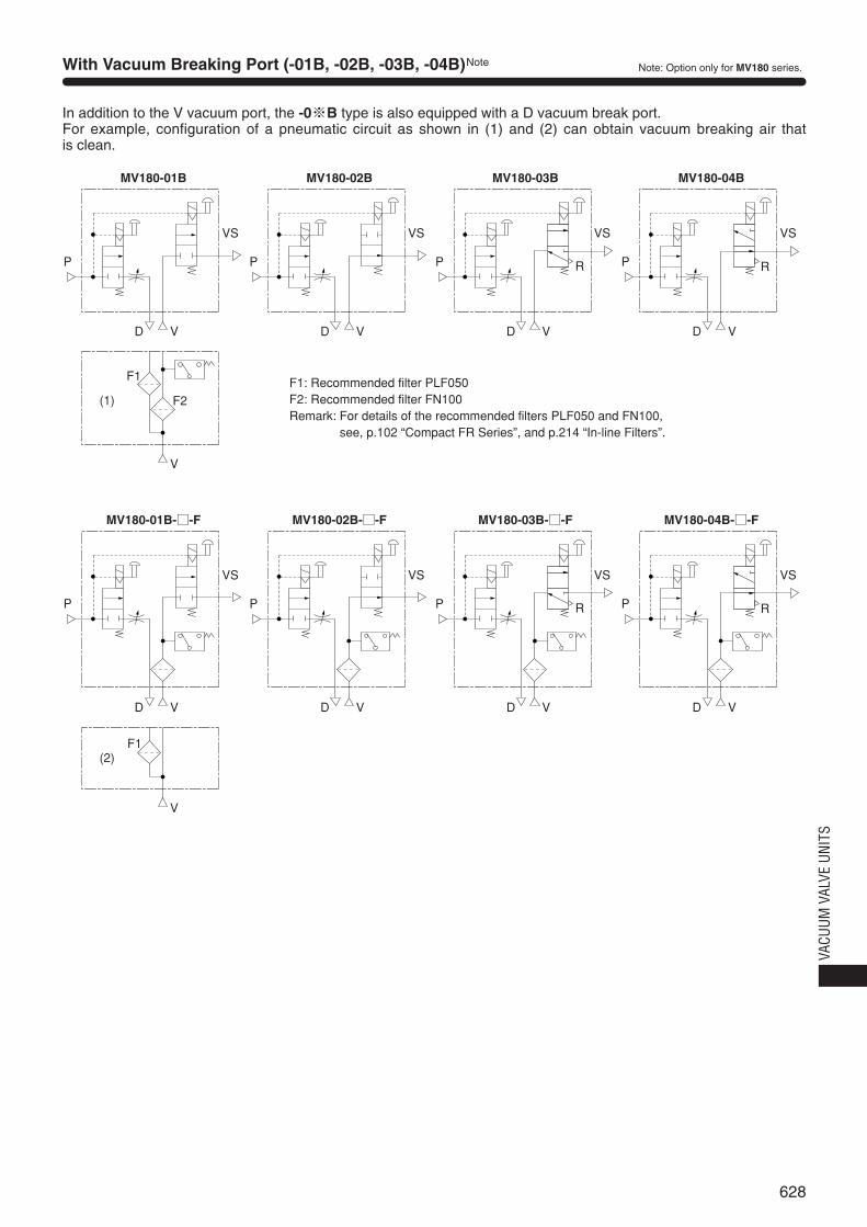
-01B, -02B, -03B, -04B typesIn addition to the V (vacuum) port, the -0※B type is also equipped witha D (vacuum break) port.For example, configuration of an air pressure circuit as shown belowcan obtain vacuum breaking air that is clean. (F1: Recommended filterPLF050)Note: Option for MV180 series only.
Pressure sensor (-EA, -ER) Vacuum breaking air separate port type (MV180-0 B)Note
P
VD
VS
V
F1
MV180-01B
621
Safety Precautions (Vacuum Valve Units)
General precautions
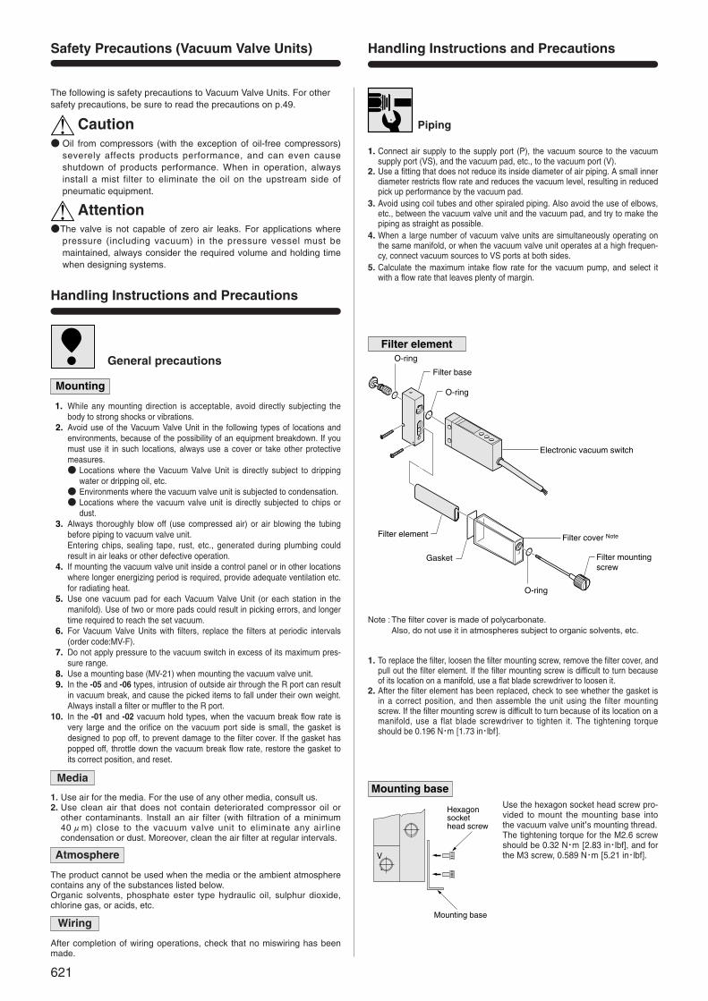
1. Connect air supply to the supply port (P), the vacuum source to the vacuumsupply port (VS), and the vacuum pad, etc., to the vacuum port (V).
2. Use a fitting that does not reduce its inside diameter of air piping. A small innerdiameter restricts flow rate and reduces the vacuum level, resulting in reducedpick up performance by the vacuum pad.
3. Avoid using coil tubes and other spiraled piping. Also avoid the use of elbows,etc., between the vacuum valve unit and the vacuum pad, and try to make thepiping as straight as possible.
4. When a large number of vacuum valve units are simultaneously operating onthe same manifold, or when the vacuum valve unit operates at a high frequen-cy, connect vacuum sources to VS ports at both sides.
5. Calculate the maximum intake flow rate for the vacuum pump, and select itwith a flow rate that leaves plenty of margin.
1. To replace the filter, loosen the filter mounting screw, remove the filter cover, andpull out the filter element. If the filter mounting screw is difficult to turn becauseof its location on a manifold, use a flat blade screwdriver to loosen it.
2. After the filter element has been replaced, check to see whether the gasket isin a correct position, and then assemble the unit using the filter mountingscrew. If the filter mounting screw is difficult to turn because of its location on amanifold, use a flat blade screwdriver to tighten it. The tightening torqueshould be 0.196 N・m [1.73 in・lbf].
Use the hexagon socket head screw pro-vided to mount the mounting base intothe vacuum valve unit’s mounting thread.The tightening torque for the M2.6 screwshould be 0.32 N・m [2.83 in・lbf], and forthe M3 screw, 0.589 N・m [5.21 in・lbf].
Piping
Gasket
Filter element
O-ring
O-ring
O-ring
Filter base
Electronic vacuum switch
Filter cover Note
Filter mounting screw
Note :The filter cover is made of polycarbonate.Also, do not use it in atmospheres subject to organic solvents, etc.
V
Hexagonsockethead screw
Mounting base
Caution
The following is safety precautions to Vacuum Valve Units. For othersafety precautions, be sure to read the precautions on p.49.
● Oil from compressors (with the exception of oil-free compressors)severely affects products performance, and can even causeshutdown of products performance. When in operation, alwaysinstall a mist filter to eliminate the oil on the upstream side ofpneumatic equipment.
Attention●The valve is not capable of zero air leaks. For applications where
pressure (including vacuum) in the pressure vessel must bemaintained, always consider the required volume and holding timewhen designing systems.
Handling Instructions and Precautions
Mounting
11. While any mounting direction is acceptable, avoid directly subjecting thebody to strong shocks or vibrations.
12. Avoid use of the Vacuum Valve Unit in the following types of locations andenvironments, because of the possibility of an equipment breakdown. If youmust use it in such locations, always use a cover or take other protectivemeasures.● Locations where the Vacuum Valve Unit is directly subject to dripping
water or dripping oil, etc.● Environments where the vacuum valve unit is subjected to condensation.● Locations where the vacuum valve unit is directly subjected to chips or
dust.13. Always thoroughly blow off (use compressed air) or air blowing the tubing
before piping to vacuum valve unit.Entering chips, sealing tape, rust, etc., generated during plumbing couldresult in air leaks or other defective operation.
14. If mounting the vacuum valve unit inside a control panel or in other locationswhere longer energizing period is required, provide adequate ventilation etc.for radiating heat.
15. Use one vacuum pad for each Vacuum Valve Unit (or each station in themanifold). Use of two or more pads could result in picking errors, and longertime required to reach the set vacuum.
16. For Vacuum Valve Units with filters, replace the filters at periodic intervals(order code:MV-F).
17. Do not apply pressure to the vacuum switch in excess of its maximum pres-sure range.
18. Use a mounting base (MV-21) when mounting the vacuum valve unit.19. In the -05 and -06 types, intrusion of outside air through the R port can result
in vacuum break, and cause the picked items to fall under their own weight.Always install a filter or muffler to the R port.
10. In the -01 and -02 vacuum hold types, when the vacuum break flow rate isvery large and the orifice on the vacuum port side is small, the gasket isdesigned to pop off, to prevent damage to the filter cover. If the gasket haspopped off, throttle down the vacuum break flow rate, restore the gasket toits correct position, and reset.
Media
1. Use air for the media. For the use of any other media, consult us.2. Use clean air that does not contain deteriorated compressor oil or
other contaminants. Install an air filter (with filtration of a minimum 40μm) close to the vacuum valve unit to eliminate any airlinecondensation or dust. Moreover, clean the air filter at regular intervals.
Atmosphere
The product cannot be used when the media or the ambient atmospherecontains any of the substances listed below.Organic solvents, phosphate ester type hydraulic oil, sulphur dioxide,chlorine gas, or acids, etc.
Wiring
After completion of wiring operations, check that no miswiring has beenmade.
Handling Instructions and Precautions
Filter element
Mounting base
622
VACU
UM V
ALVE
UNI
TS
Lock nut
Solenoid Plug connectorManual override
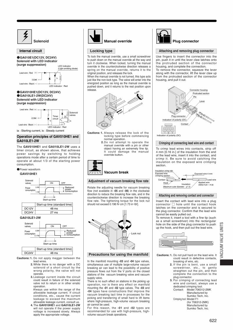
To lock the manual override, use a small screwdriverto push down on the manual override all the way andturn it clockwise. When locked, turning the manualoverride in the counterclockwise direction releases aspring on the manual override, returns it to theoriginal position, and releases the lock.When the manual override is not turned, this type actsjust like the non-lock type. The valve will enter into theenergized position as long as the manual override ispushed down, and it returns to the rest position uponrelease.
+ C-
Contact
Lever
Plug connector
Indication of polarity (DC)
Protruded section
Pin
Connector housing
Indication of polarity (DC)
Hook
Exposed wire crimping section
Insulation crimp tab
Contact
Exposed wire 4 mm
Lead wire
Insulation(Maximum outer diameter : φ1.5)
Applied wire AWG#24~#30
PUSH
TURN
LED indicator(Light emitting diode)
LED indicator : Red
Lead wire : Red
Lead wire : Black
(+)
(-)
(COM)
ia
is
LED indicator : Red
Timer circuit
Lead wire : Red
Lead wire : Black
Solenoid valves
(+)
(-)
(COM)
ia : Starting current, is : Steady current
DC24V 48 msStart-up time (standard time)
DC12VDC24V
48 ms27 ms
Start-up time (standard time)
ON OFF
3.2W
1.1W
Solenoid valves
Power consumption
Reduced power consumption
Start-up time
ON OFF
0.5W
0.17W
Solenoid valves
Power consumption
Reduced power consumption
Start-up time
●Power waveform
GAV010HE1
GA010LE1-2W
Vacuum break
Internal circuit
●GA010E1(DC12V, DC24V)Solenoid with LED indicator(surge suppression)
●GAV010HE1(DC12V, DC24V)●GA010LE1-2W(DC24V)Solenoid with LED indicator(surge suppression)
Operation principles of GAV010HE1 andGA010LE1-2W
The GAV010HE1 and GA010LE1-2W uses atimer circuit, as shown above, that achievespower savings by switching to holdingoperations mode after a certain period of time tooperate at about 1/3 of the starting powerconsumption.
Cautions: 1. Do not apply megger between thelead wires.
2. While there is no danger with a DCsolenoid of a short circuit by thewrong polarity, the valve will notoperate.
3. Leakage current inside the circuitcould result in failure of the solenoidvalve not to return or in other erraticoperation.
3.Always use within the range of theallowable leakage current. If circuitconditions, etc., cause the currentleakage to exceed the maximumallowable leakage current, consult us.
4. The GAV010HE1 and GA010LE1-2Wwill not operate if the power supplyvoltage is increased slowly. Alwaysapply the appropriate voltage.
Locking type
Cautions: 1. Always release the lock of thelocking type before commencingnormal operation.
2. Do not attempt to operate themanual override with a pin or otherobject having an extremely fine tip.It could damage the manualoverride button.
Adjustment of vacuum breaking flow rate
Rotate the adjusting needle for vacuum breakingflow (not available in -05 and -06) in the clockwisedirection to reduce the breaking flow rate, and in thecounterclockwise direction to increase the breakingflow rate. The tightening torque for the lock nutshould not exceed 0.196 N・cm [1.73 in・lbf].
Precautions for using the manifold
In the manifold mounting -03 and -04 type valves,simultaneous use of multiple large-volume vacuumbreaking air can lead to the possibility of positivepressure flows out from the V ports on the closedstations of the vacuum breaking valve and vacuumsupply valve.There is no such effect on stations in the picking upoperation, nor is there any effect on manifoldmounting the -01 and -02 type valves. The -03 and -04 types have constructions that improve thevacuum breaking tact time in processes for thepicking and transferring of small hard to lift itemswhere high-pressure, high-volume vacuum breakingair cannot be used.For this reason, the -01 and -02 types arerecommended for use with high-pressure, high-volume vacuum break operations.
Attaching and removing plug connector
Use fingers to insert the connector into thepin, push it in until the lever claw latches ontothe protruded section of the connectorhousing, and complete the connection.To remove the connector, squeeze the leveralong with the connector, lift the lever claw upfrom the protruded section of the connectorhousing, and pull it out.
Crimping of connecting lead wire and contact
To crimp lead wires into contacts, strip off 4 mm [0.16 in.] of the insulation from the endof the lead wire, insert it into the contact, andcrimp it. Be sure to avoid catching theinsulation on the exposed wire crimpingsection.
Attaching and removing contact and connector
Insert the contact with lead wire into a plugconnector □ hole until the contact hooklatches on the connector and is secured tothe plug connector. Confirm that the lead wirecannot be easily pulled out.To remove it, insert a tool with a fine tip (suchas a small screwdriver) into the rectangularhole on the side of the plug connector to pushup the hook, and then pull out the lead wire.
Cautions: 1. Do not pull hard on the lead wire. Itcould result in defective contacts,breaking of wire, etc.
2. If the pin is bent, use a smallscrewdriver, etc., to gentlystraighten out the pin, and thencomplete the connection to theplug connector.
3. For crimping of connecting leadwire and contact, always use adedicated crimping tool.Contact: Model 706312-2MK
Manufactured by Sumiko Tech, Inc.
Crimping tool: Model F1 (for 706312-2MK)Manufactured by Sumiko Tech, Inc.
623
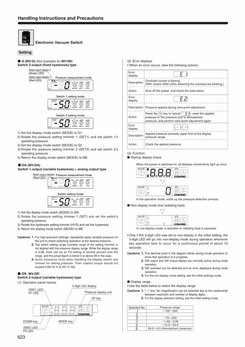
Electronic Vacuum Switch
●-DA (MV-DA)Switch 1-output (variable hysteresis) + analog output type
1) Set the display mode switch (MODE) to S1.2) Rotate the pressure setting trimmer 1 (SET1) and set switch 1’s
operating pressure.3) Set the display mode switch (MODE) to S2.4) Rotate the pressure setting trimmer 2 (SET2) and set switch 2’s
operating pressure.5) Return the display mode switch (MODE) to ME.
1) Set the display mode switch (MODE) to SW.2) Rotate the pressure setting trimmer 1 (SET) and set the switch’s
operating pressure.3) Rotate the hysteresis setting trimmer (HYS) and set the hysteresis.4) Return the display mode switch (MODE) to ME.
Handling Instructions and Precautions
MODE
SW ME
kPa SET HYS
MODE
SW ME
kPa SET HYS
Switch setting mode
Pressure measurement modeSwitch output indicator(Red LED)
MODE
S1S2 ME
kPa SET1 SET2
MODE
S1S2 ME
kPa SET1 SET2
MODE
S1S2 ME
kPa SET1 SET2
Switch 1 setting mode
Switch 2 setting mode
Switch output indicator 1(Red LED)
Switch output indicator 2(Green LED)
Pressure measurement mode
●-DR(MV-DR)Switch 2-output (variable hysteresis) type
(1) Operation panel names
(2) Error displays• When an error occurs, take the following actions.
(3) Function■ Startup display check
■ Non-display mode (low radiating heat)
• Only if the 3-digit LED was set to non-display in the initial setting, the3-digit LED will go into non-display mode during operation wheneverkey operation fails to occur for a continuous period of about 10seconds.
kPa
P2
MV-DRP1
3-digit LED display
Pressure display unit
UP key
MODE keyDOWN key
(SW2)LED P2 LED
(SW1)LED P1 LED
Error display
Description Overload current is flowing.(SW1 and/or SW2 LEDs detecting the overload are blinking.)
Press the key to cancel , reset the applied pressure to the pressure port to atmospheric pressure, and perform zero-point adjustment again.
Action
Error display
Description
Action
Action
Error display
Description
Shut off the power, and check the load status.
Pressure applied during zero-point adjustment.
Applied pressure exceeds upper limit of the display pressure range.
Check the applied pressure.
kPa
P2
MV-DRP1
kPa
P2
MV-DRP1
When the power is switched on, all displays momentarily light up once.
In the operation mode, starts up the pressure detection process.
kPa
P2
MV-DRP1
In non-display mode, a reduction in radiating heat is expected.
■ Display range• Use the table below to select the display range.
Selected No. Pressure range-100~300
―-75~225-1.00~3.00-14.5~43.5
29.5~0.0 (Atmospheric pressure)
Setting
●-D (MV-D) (Not available for MV180)Switch 2-output (fixed hysteresis) type
Cautions: 1. For high-precision settings, repeatedly apply variable pressure onthe unit to check switching operation at the desired pressure.
2. The switch setting range (variable range of the setting trimmer) isnot aligned with the pressure display range. While the display rangeis 0-99, there can be an FS setting of several percent over therange, and the actual figure is below 0 or above 99 in the case.
3. Avoid excessive force when handling the display switch andtrimmer for setting pressure. Their rotation torque should notexceed 0.025 N・m [0.221 in・lbf].
Cautions: 1. The decimal point in the diagram blinks during mode operation toshow that operation is in progress.
2. SW output and SW output display are normally active during modeoperation.
3. SW overload can be detected and an error displayed during modeoperation.
4. For the non-display mode setting, see the initial settings mode.
Cautions: 1. “—” line: No magnification can be selected due to the relationshipbetween resolution and number of display digits.
2. For the display selection setting, see the initial setting mode.
624
VACU
UM V
ALVE
UNI
TS
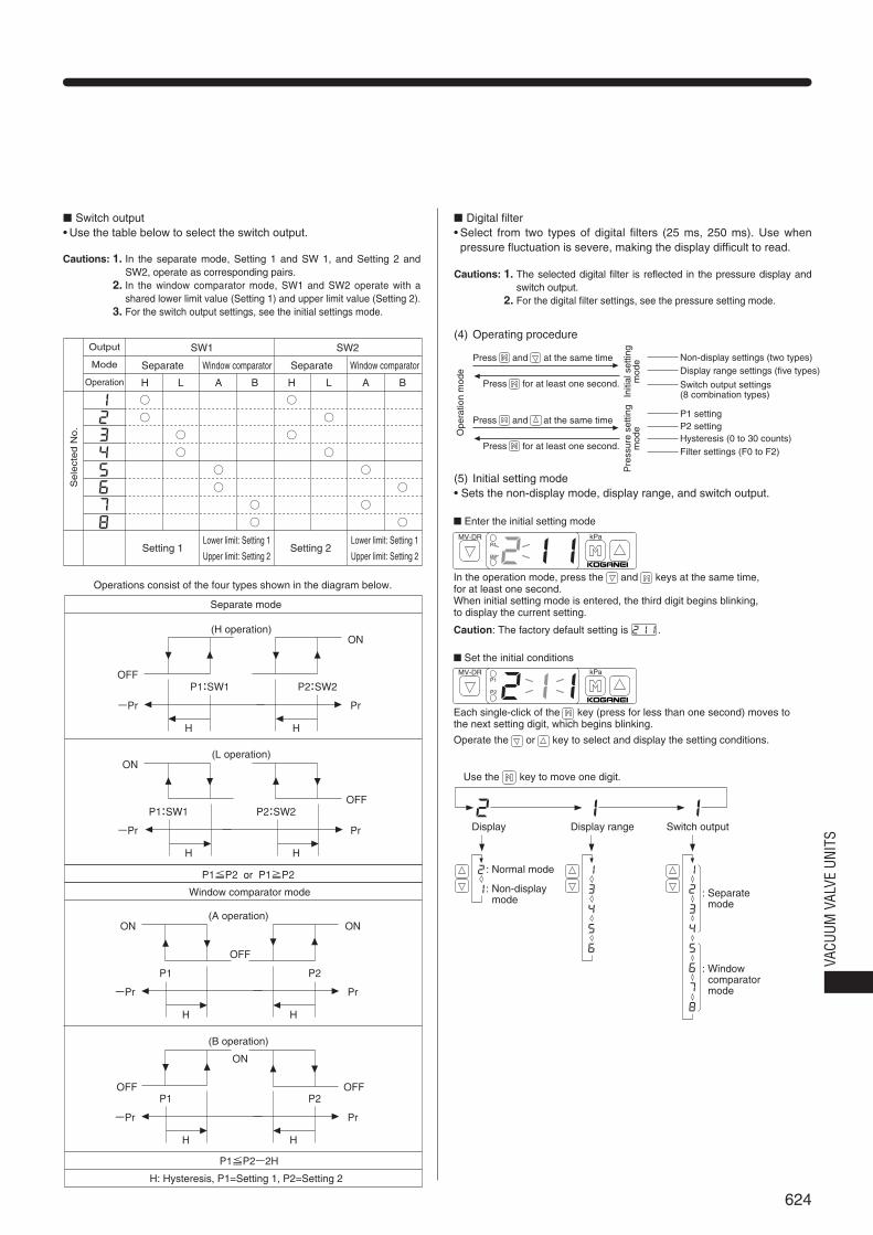
■ Switch output• Use the table below to select the switch output.
SW1 SW2
Separate
Setting 1Lower limit: Setting 1
Upper limit: Setting 2Setting 2
Lower limit: Setting 1
Upper limit: Setting 2
Window comparator Separate Window comparator
H
○
○
L
○
○
A
○
○
B
○
○
H
○
○
L
○
○
A
○
○
B
○
○
Operations consist of the four types shown in the diagram below.
(H operation)
OFF
-Pr
ON
Pr
P1:SW1
H
P2:SW2
H
(L operation)
OFF
-Pr
ON
Pr
P1:SW1
H
P2:SW2
H
(A operation)
OFF
-Pr
ONON
Pr
P1
H
P2
H
(B operation)
OFF OFF
-Pr
ON
Pr
P1
H
P2
H
Separate mode
Window comparator mode
P1≦P2 or P1≧P2
P1≦P2-2H
H: Hysteresis, P1=Setting 1, P2=Setting 2
Se
lect
ed
No
.
Output
Mode
Operation
■ Digital filter• Select from two types of digital filters (25 ms, 250 ms). Use whenpressure fluctuation is severe, making the display difficult to read.
(4) Operating procedure
(5) Initial setting mode• Sets the non-display mode, display range, and switch output.
Press and at the same time
Press and at the same time
Press for at least one second.
Press for at least one second.
Initi
al s
ettin
gm
ode Non-display settings (two types)
Display range settings (five types)
Switch output settings (8 combination types)
Ope
ratio
n m
ode
Pre
ssur
e se
tting
mod
e
P1 settingP2 settingHysteresis (0 to 30 counts)Filter settings (F0 to F2)
kPa
P2
MV-DRP1
■ Enter the initial setting mode
kPa
P2
MV-DRP1
■ Set the initial conditions
Display
: Normal mode
: Separate mode
: Non-display mode
Display range Switch output
: Window comparator mode
In the operation mode, press the and keys at the same time, for at least one second.When initial setting mode is entered, the third digit begins blinking, to display the current setting.
Caution: The factory default setting is .
Each single-click of the key (press for less than one second) moves to the next setting digit, which begins blinking.
Operate the or key to select and display the setting conditions.
Use the key to move one digit.
Cautions: 1. In the separate mode, Setting 1 and SW 1, and Setting 2 andSW2, operate as corresponding pairs.
2. In the window comparator mode, SW1 and SW2 operate with ashared lower limit value (Setting 1) and upper limit value (Setting 2).
3. For the switch output settings, see the initial settings mode.
Cautions: 1. The selected digital filter is reflected in the pressure display andswitch output.
2. For the digital filter settings, see the pressure setting mode.
625
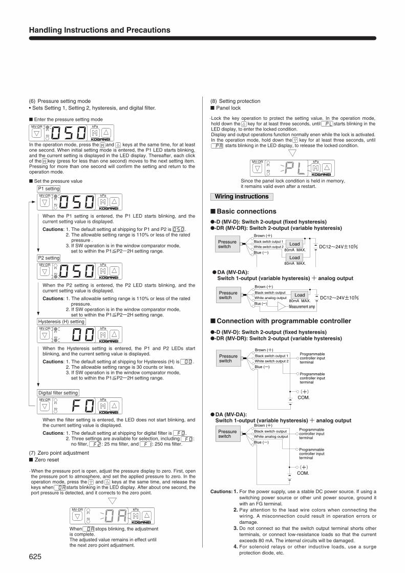
(7) Zero point adjustment■ Zero reset
(8) Setting protection■ Panel lock
(6) Pressure setting mode• Sets Setting 1, Setting 2, hysteresis, and digital filter.
Handling Instructions and Precautions
kPa
P2
MV-DRP1
■ Enter the pressure setting mode
kPa
P2
MV-DRP1
■ Set the pressure value
P1 setting
kPa
P2
MV-DRP1
Hysteresis (H) setting
kPa
P2
MV-DRP1
Digital filter setting
kPa
P2
MV-DRP1
P2 setting
In the operation mode, press the and keys at the same time, for at least one second. When initial setting mode is entered, the P1 LED starts blinking, and the current setting is displayed in the LED display. Thereafter, each click of the key (press for less than one second) moves to the next setting item. Pressing for more than one second will confirm the setting and return to the operation mode.
1. The default setting at shipping for P1 and P2 is .2. The allowable setting range is 110% or less of the rated
pressure .3. If SW operation is in the window comparator mode,
set to within the P1≦P2-2H setting range.
When the P1 setting is entered, the P1 LED starts blinking, and the current setting value is displayed.
Cautions:
1. The allowable setting range is 110% or less of the rated pressure.
2. If SW operation is in the window comparator mode, set to within the P1≦P2-2H setting range.
When the P2 setting is entered, the P2 LED starts blinking, and the current setting value is displayed.
Cautions:
1. The default setting at shipping for Hysteresis (H) is .2. The allowable setting range is 30 counts or less. 3. If SW operation is in the window comparator mode,
set to within the P1≦P2-2H setting range.
When the Hysteresis setting is entered, the P1 and P2 LEDs start blinking, and the current setting value is displayed.
Cautions:
1. The default setting at shipping for digital filter is .2. Three settings are available for selection, including :
no filter, : 25 ms filter, and : 250 ms filter.
When the filter setting is entered, the LED does not start blinking, and the current setting value is displayed.
Cautions:
kPa
P2
MV-DRP1
·When the pressure port is open, adjust the pressure display to zero. First, openthe pressure port to atmosphere, and set the applied pressure to zero. In the operation mode, press the and keys at the same time, and release the keys when starts blinking in the LED display. After about one second, the port pressure is detected, and it corrects to the zero point.
When stops blinking, the adjustment is complete.The adjusted value remains in effect until the next zero point adjustment.
kPa
P2
MV-DRP1
Since the panel lock condition is held in memory, it remains valid even after a restart.
·Lock the key operation to protect the setting value. In the operation mode, hold down the key for at least three seconds, until starts blinking in the LED display, to enter the locked condition.Display and output operations function normally enen while the lock is activated. In the operation mode, hold down the key for at least three seconds, until starts blinking in the LED display, to release the locked condition.
Wiring instructions
Pressure switch
80mA MAX.
80mA MAX.Load
Load DC12~24V±10%
Brown (+)
Black switch output 1
White switch output 2
Blue (-)
Pressure switch
80mA MAX.
Measurement amp
Load DC12~24V±10%
Brown (+)
Black switch output
White analog output
Blue (-)
(+) COM.
Programmable controller input terminal
Programmable controller input terminal
Pressure switch
Brown (+)
Black switch output 1
White switch output 2
Blue (-)
(+) COM.
Programmable controller input terminal
Programmable controller input terminal
Pressure switch
Brown (+)
Black switch output
White analog output
Blue (-)
●-D (MV-D): Switch 2-output (fixed hysteresis)●-DR (MV-DR): Switch 2-output (variable hysteresis)
■ Basic connections
■ Connection with programmable controller
● DA (MV-DA):Switch 1-output (variable hysteresis) + analog output
●-D (MV-D): Switch 2-output (fixed hysteresis)●-DR (MV-DR): Switch 2-output (variable hysteresis)
● DA (MV-DA):Switch 1-output (variable hysteresis) + analog output
Cautions: 1. For the power supply, use a stable DC power source. If using aswitching power source or other unit power source, ground itwith an FG terminal.
2. Pay attention to the lead wire colors when connecting thewiring. A misconnection could result in operation errors ordamage.
3. Do not connect so that the switch output terminal shorts otherterminals, or connect low-resistance loads so that the currentexceeds 80 mA. The internal circuits will be damaged.
4. For solenoid relays or other inductive loads, use a surgeprotection diode, etc.
626
VACU
UM V
ALVE
UNI
TS
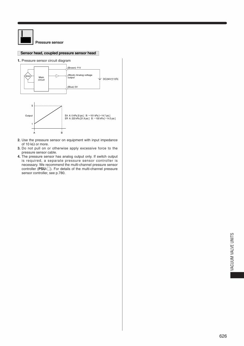
Pressure sensor
Sensor head, coupled pressure sensor head
1. Pressure sensor circuit diagram
2. Use the pressure sensor on equipment with input impedanceof 10 kΩ or more.
3. Do not pull on or otherwise apply excessive force to thepressure sensor cable.
4. The pressure sensor has analog output only. If switch outputis required, a separate pressure sensor controller isnecessary. We recommend the multi-channel pressure sensorcontroller (PSU-□). For details of the multi-channel pressuresensor controller, see p.780.
(Blue) 0V
DC24V±10%
EA A: 0 kPa [0 psi.] B: -101 kPa [-14.7 psi.]ER A: 220 kPa [31.9 psi.] B: -100 kPa [-14.5 psi.]
5
1
A B
SensorMaincircuit
(Brown) +V
(Block) Analog voltage output
Output
627
How to Choose 2-Way or 3-Way Valves
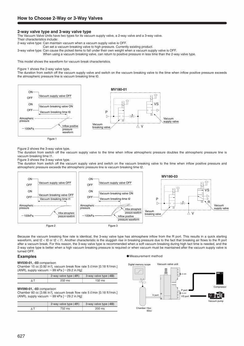
2-way valve type and 3-way valve typeThe Vacuum Valve Units have two types for its vacuum supply valve, a 2-way valve and a 3-way valve.Their characteristics include:2-way valve type: Can maintain vacuum when a vacuum supply valve is OFF.
Can set a vacuum breaking valve to high pressure. Currently existing product.3-way valve type: Can cause the picked items to fall under their own weight when a vacuum supply valve is OFF.
When using a vacuum breaking valve, can return to positive pressure in less time than the 2-way valve type.
This model shows the waveform for vacuum break characteristics.
Figure 1 shows the 2-way valve type.The duration from switch off the vacuum supply valve and switch on the vacuum breaking valve to the time when inflow positive pressure exceedsthe atmospheric pressure line is vacuum breaking time t0.
Examples ● Measurement method
MV030-01, -03 comparisonChamber 15 cc [0.92 in.3], vacuum break flow rate 5R/min [0.18 ft.3/min.](ANR), supply vacuum -99 kPa [-29.2 in.Hg]
MV090-01, -03 comparisonChamber 60 cc [3.66 in.3], vacuum break flow rate 5R/min [0.18 ft.3/min.](ANR), supply vacuum -99 kPa [-29.2 in.Hg]
Vacuum breaking time t0
Vacuum supply valve OFF
Vacuum breaking valve ONON
OFF
ON
OFF
-100kPa
Figure 1
Vacuumsupply valve
Vacuumbreaking valve
MV180-01
P
V
VS
Atmosphericpressure
Inflow positivepressure waveform
Vacuum breaking time t1
Vacuum supply valve OFF
Vacuum breaking valve OFFON
OFF
ON
OFF
-100kPa
Vacuum breaking time t2
Vacuum supply valve OFF
Vacuum breaking valve ONON
OFF
ON
OFF
-100kPa
MV180-03
P
V
VS
R
Figure 2 Figure 3
Atmosphericpressure
Inflow atmosphericpressure waveform
Atmosphericpressure Inflow atmospheric
pressure waveformInflow positivepressure waveform
Vacuumbreaking valve
Vacuumsupply valve
Digital memory scope
Chamber
15cc60cc
Compressor
Vacuum pump
Vacuum valve unit
V port
P port
VS port
ΔT
2-way valve type (-01)
232 ms
3-way valve type (-03)
132 ms
ΔT
2-way valve type (-01)
732 ms
3-way valve type (-03)
200 ms
Figure 2 shows the 3-way valve type.The duration from switch off the vacuum supply valve to the time when inflow atmospheric pressure doubles the atmospheric pressure line isvacuum breaking time t1.Figure 3 shows the 3-way valve type.The duration from switch off the vacuum supply valve and switch on the vacuum breaking valve to the time when inflow positive pressure andatmospheric pressure exceeds the atmospheric pressure line is vacuum breaking time t2.
Because the vacuum breaking flow rate is identical, the 3-way valve type has atmosphere inflow from the R port. This results in a quick startingwaveform, and t2 < t0 or t2 < t1. Another characteristic is the sluggish rise in breaking pressure due to the fact that breaking air flows to the R portafter a vacuum break. For this reason, the 3-way valve type is recommended when a soft vacuum breaking during high tact time is needed, and the2-way valve type is better when a high vacuum breaking pressure is required or when vacuum must be maintained after the vacuum supply valve isturned OFF.
628
VACU
UM V
ALVE
UNI
TS
With Vacuum Breaking Port (-01B, -02B, -03B, -04B)Note Note: Option only for MV180 series.
In addition to the V vacuum port, the -0※B type is also equipped with a D vacuum break port.For example, configuration of a pneumatic circuit as shown in (1) and (2) can obtain vacuum breaking air that is clean.
MV180-01B
P
VD
F1
F2(1)
VS
MV180-02B
P
VD
VS
MV180-03B
P
VD
VS
R
MV180-04B
P
VD
VS
R
V
MV180-01B-□-F
P
VD
(2)
VS
MV180-02B-□-F
P
VD
VS
MV180-03B-□-F
P
VD
VS
R
MV180-04B-□-F
P
VD
VS
R
V
F1
F1: Recommended filter PLF050 F2: Recommended filter FN100 Remark: For details of the recommended filters PLF050 and FN100,
see, p.102 “Compact FR Series”, and p.214 “In-line Filters”.
629
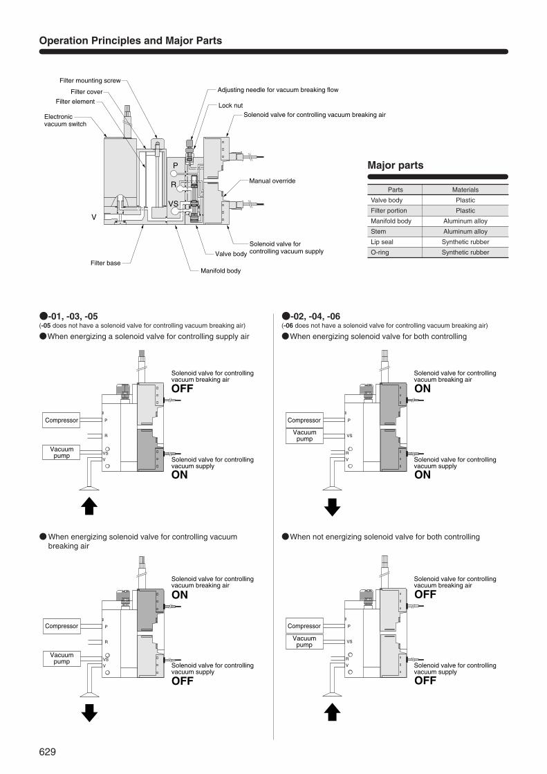
Operation Principles and Major Parts
●When energizing a solenoid valve for controlling supply air
●-01, -03, -05(-05 does not have a solenoid valve for controlling vacuum breaking air)
●-02, -04, -06(-06 does not have a solenoid valve for controlling vacuum breaking air)
●When energizing solenoid valve for controlling vacuumbreaking air
●When energizing solenoid valve for both controlling
●When not energizing solenoid valve for both controlling
P
R
VS
V
Filter element
Solenoid valve for controlling vacuum breaking airLock nut
Adjusting needle for vacuum breaking flow
Solenoid valve for controlling vacuum supply
Manual override
Valve body
Manifold bodyFilter base
Filter mounting screw
Electronic vacuum switch
Filter cover
Major parts
Parts
Valve body
Filter portion
Manifold body
Stem
Lip seal
O-ring
Materials
Plastic
Plastic
Aluminum alloy
Aluminum alloy
Synthetic rubber
Synthetic rubber
P
R
VVS
Compressor
Solenoid valve for controlling vacuum breaking air
Solenoid valve for controlling vacuum supply
Vacuumpump
OFF
ON
P
R
VVS
ON
OFF
Compressor
Solenoid valve for controlling vacuum breaking air
Solenoid valve for controlling vacuum supply
Vacuumpump
P
VS
V
R
ON
ON
Compressor
Solenoid valve for controlling vacuum breaking air
Solenoid valve for controlling vacuum supply
Vacuumpump
P
VS
V
R
OFF
OFF
Compressor
Solenoid valve for controlling vacuum breaking air
Solenoid valve for controlling vacuum supply
Vacuumpump
630
VACU
UM V
ALVE
UNI
TS
Air
1.05 [152]
5~50 [41~122]
Prohibited
30
Any
2 or 3 ports
Normally closed (NC)/Normally open (NO)
1373 [140] (axial direction 196 [20])
MV030 MV090Item
Basic model
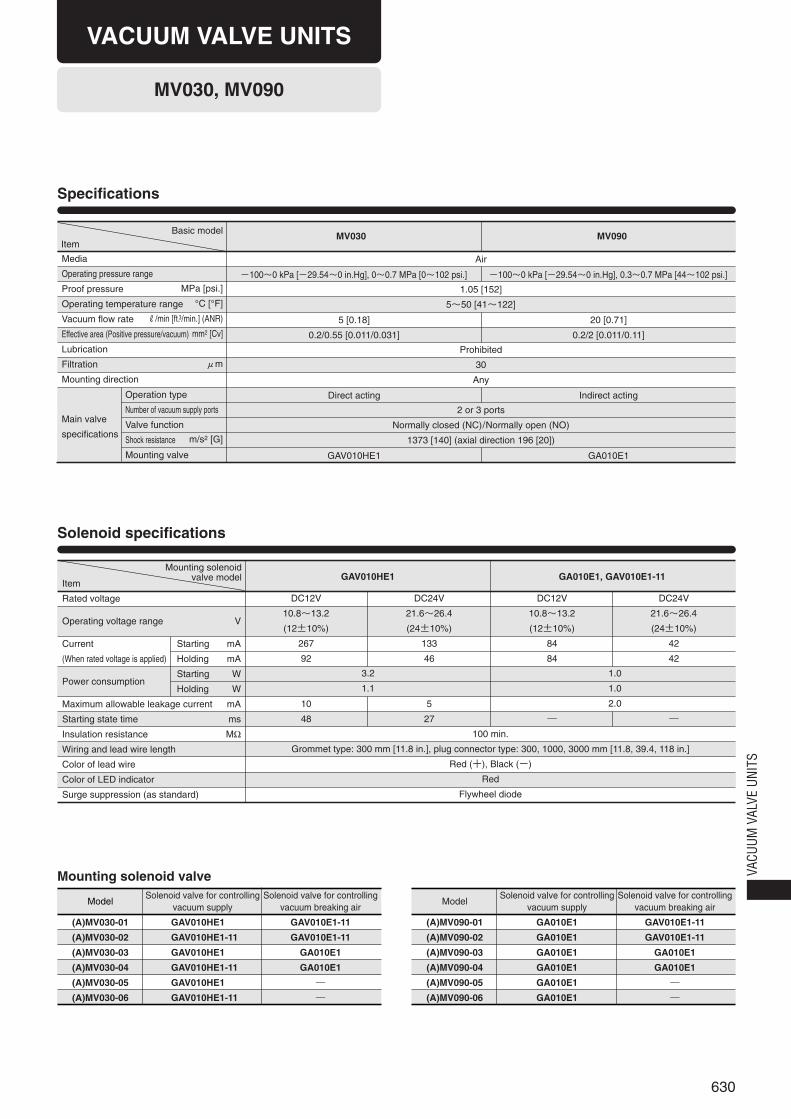
MV030, MV090
Specifications
Solenoid specifications
Mounting solenoid valve
Media
Operating pressure range
Proof pressure
Operating temperature range
Vacuum flow rate
Effective area (Positive pressure/vacuum)
Lubrication
Filtration
Mounting direction
Main valve
specifications
Operation type
Number of vacuum supply ports
Valve function
Shock resistance
Mounting valve
MPa [psi.]
°C [°F]
R/min [ft.3/min.] (ANR)
mm2 [Cv]
μm
m/s2 [G]
-100~0 kPa [-29.54~0 in.Hg], 0~0.7 MPa [0~102 psi.]
5 [0.18]
0.2/0.55 [0.011/0.031]
Direct acting
GAV010HE1
-100~0 kPa [-29.54~0 in.Hg], 0.3~0.7 MPa [44~102 psi.]
20 [0.71]
0.2/2 [0.011/0.11]
Indirect acting
GA010E1
Item
Rated voltage
Operating voltage range
Current
(When rated voltage is applied)
Power consumption
Maximum allowable leakage current
Starting state time
Insulation resistance
Wiring and lead wire length
Color of lead wire
Color of LED indicator
Surge suppression (as standard)
DC12V
10.8~13.2
(12±10%)
267
92
10
48
DC24V
21.6~26.4
(24±10%)
133
46
5
27
DC12V
10.8~13.2
(12±10%)
84
84
―
DC24V
21.6~26.4
(24±10%)
42
42
―
V
mA
mA
W
W
mA
ms
MΩ 100 min.
Grommet type: 300 mm [11.8 in.], plug connector type: 300, 1000, 3000 mm [11.8, 39.4, 118 in.]
Red (+), Black (-)
Red
Flywheel diode
3.2
1.1
GAV010HE1 GA010E1, GAV010E1-11
1.0
1.0
2.0
Model
(A)MV030-01
(A)MV030-02
(A)MV030-03
(A)MV030-04
(A)MV030-05
(A)MV030-06
Solenoid valve for controllingvacuum breaking air
GAV010E1-11
GAV010E1-11
GA010E1
GA010E1
―
―
Solenoid valve for controllingvacuum supply
GAV010HE1
GAV010HE1-11
GAV010HE1
GAV010HE1-11
GAV010HE1
GAV010HE1-11
Model
(A)MV090-01
(A)MV090-02
(A)MV090-03
(A)MV090-04
(A)MV090-05
(A)MV090-06
Solenoid valve for controllingvacuum breaking air
GAV010E1-11
GAV010E1-11
GA010E1
GA010E1
―
―
Solenoid valve for controllingvacuum supply
GA010E1
GA010E1
GA010E1
GA010E1
GA010E1
GA010E1
Starting
Holding
Starting
Holding
VACUUM VALVE UNITS
Mounting solenoidvalve model
631
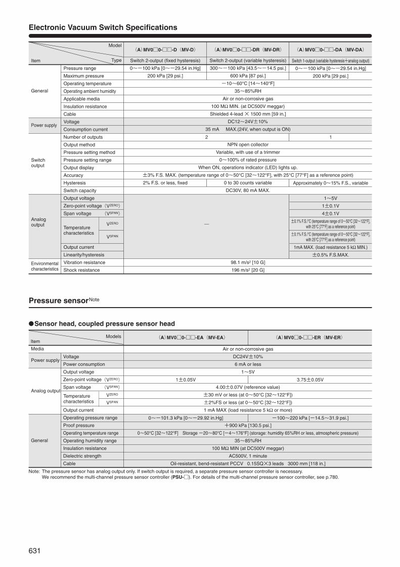
Electronic Vacuum Switch Specifications
Model
Item
Pressure range
Maximum pressure
Operating temperature
Operating ambient humidity
Applicable media
Insulation resistance
Cable
Voltage
Consumption current
Number of outputs
Output method
Pressure setting method
Pressure setting range
Output display
Accuracy
Hysteresis
Switch capacity
Output voltage
Zero-point voltage
Span voltage
Temperature characteristics
Output current
Linearity/hysteresis
Vibration resistance
Shock resistance
General
Power supply
Switch output
Analog output
Environmental characteristics
2
―
Switch 2-output (fixed hysteresis)
0~-100 kPa [0~-29.54 in.Hg]
200 kPa [29 psi.]
2% F.S. or less, fixed
Switch 1-output (variable hysteresis+analog output)
0~-100 kPa [0~-29.54 in.Hg]
200 kPa [29 psi.]
1
Approximately 0~15% F.S., variable
1~5V
1±0.1V
4±0.1V
±0.1% F.S./°C (temperature range of 0~50°C [32~122°F], with 25°C [77°F] as a reference point)
±0.1% F.S./°C (temperature range of 0~50°C [32~122°F], with 25°C [77°F] as a reference point)
1mA MAX. (load resistance 5 kΩ MIN.)
±0.5% F.S.MAX.
Switch 2-output (variable hysteresis)
300~-100 kPa [43.5~-14.5 psi.]
600 kPa [87 psi.]
-10~60°C [14~140°F]
35~85%RH
Air or non-corrosive gas
100 MΩ MIN. (at DC500V meggar)
Shielded 4-lead × 1500 mm [59 in.]
DC12~24V±10%
35 mA MAX.(24V, when output is ON)
NPN open collector
Variable, with use of a trimmer
0~100% of rated pressure
When ON, operations indicator (LED) lights up.
±3% F.S. MAX. (temperature range of 0~50°C [32~122°F], with 25°C [77°F] as a reference point)
0 to 30 counts variable
DC30V, 80 mA MAX.
98.1 m/s2 [10 G]
196 m/s2 [20 G]
(A)MV0□0-□□-D(MV-D) (A)MV0□0-□□-DR(MV-DR) (A)MV0□0-□□-DA(MV-DA)
(VZERO)
(VSPAN)
VZERO
VSPAN
Air or non-corrosive gas
DC24V±10%
6 mA or less
1~5V
4.00±0.07V (reference value)
±30 mV or less (at 0~50°C [32~122°F])
±2%FS or less (at 0~50°C [32~122°F])
1 mA MAX (load resistance 5 kΩ or more)
+900 kPa [130.5 psi.]
0~50°C [32~122°F] Storage -20~80°C [-4~176°F] (storage: humidity 65%RH or less, atmospheric pressure)
35~85%RH
100 MΩ MIN (at DC500V meggar)
AC500V, 1 minute
Oil-resistant, bend-resistant PCCV 0.15SQ×3 leads 3000 mm [118 in.]
(A)MV0□0-□□-EA(MV-EA) (A)MV0□0-□□-ER(MV-ER)Item
Pressure sensorNote
Media
Power supply
Analog output
General
Voltage
Power consumption
Output voltage
Zero-point voltage
Span voltage
Output current
Operating pressure range
Proof pressure
Operating temperature range
Operating humidity range
Insulation resistance
Dielectric strength
Cable
1±0.05V
0~-101.3 kPa [0~-29.92 in.Hg]
3.75±0.05V
-100~220 kPa [-14.5~31.9 psi.]
●Sensor head, coupled pressure sensor head
Note: The pressure sensor has analog output only. If switch output is required, a separate pressure sensor controller is necessary.We recommend the multi-channel pressure sensor controller (PSU-□). For details of the multi-channel pressure sensor controller, see p.780.
Type
Models
Temperaturecharacteristics
(VZERO)
(VSPAN)
VZERO
VSPAN
632
VACU
UM V
ALVE
UNI
TS
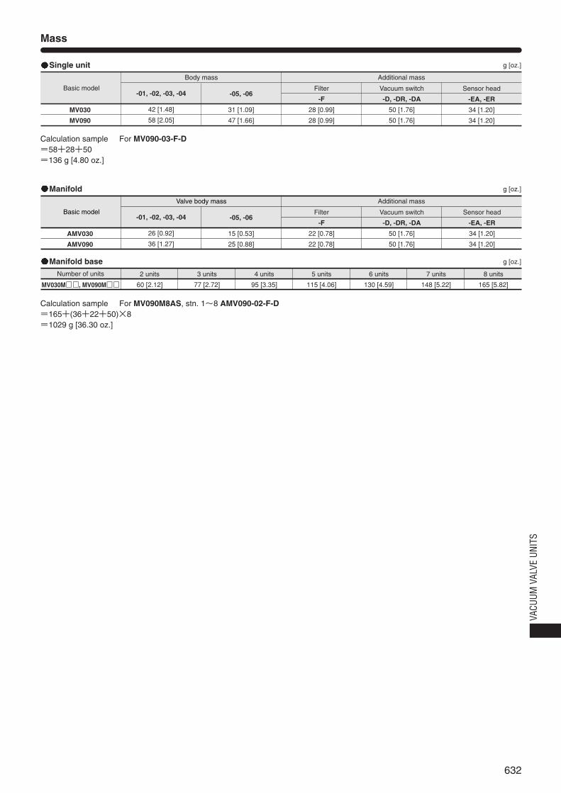
Mass
Basic model
Body mass
-01, -02, -03, -04
42 [1.48]
58 [2.05]
-05, -06
31 [1.09]
47 [1.66]
Additional mass
Filter
-F
28 [0.99]
28 [0.99]
Vacuum switch
-D, -DR, -DA
50 [1.76]
50 [1.76]
Sensor head
-EA, -ER
34 [1.20]
34 [1.20]
MV030
MV090
g [oz.]Single unit
Calculation sample For MV090-03-F-D=58+28+50=136 g [4.80 oz.]
Basic model
Valve body mass
-01, -02, -03, -04
26 [0.92]
36 [1.27]
-05, -06
15 [0.53]
25 [0.88]
Additional mass
Filter
-F
22 [0.78]
22 [0.78]
Vacuum switch
-D, -DR, -DA
50 [1.76]
50 [1.76]
Sensor head
-EA, -ER
34 [1.20]
34 [1.20]
AMV030
AMV090
MV030M□□, MV090M□□
g [oz.]Manifold
Number of units 2 units
60 [2.12]
3 units
77 [2.72]
4 units
95 [3.35]
5 units
115 [4.06]
6 units
130 [4.59]
7 units
148 [5.22]
8 units
165 [5.82]
g [oz.]Manifold base
Calculation sample For MV090M8AS, stn. 1~8 AMV090-02-F-D=165+(36+22+50)×8=1029 g [36.30 oz.]
633
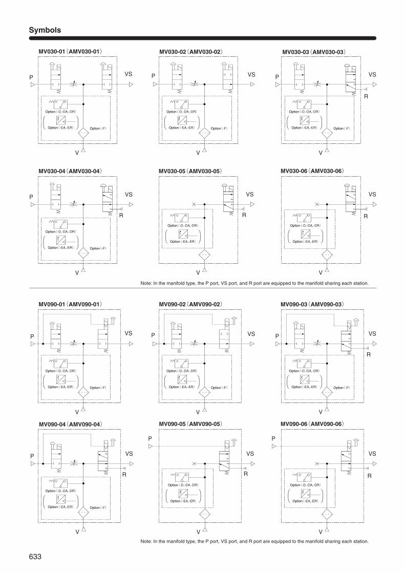
Symbols
MV030-01(AMV030-01) MV030-02(AMV030-02)
P VSP
V
VS P VS
MV030-03(AMV030-03)
R
P VS
MV030-04(AMV030-04)
VS
MV030-05(AMV030-05)
R
VS
MV030-06(AMV030-06)
R R
Option(-D,-DA,-DR)
Option(-F) Option(-EA,-ER)
V V
V V V
Note: In the manifold type, the P port, VS port, and R port are equipped to the manifold sharing each station.
Note: In the manifold type, the P port, VS port, and R port are equipped to the manifold sharing each station.
MV090-01(AMV090-01) MV090-02(AMV090-02)
P VSP
V
VS P VS
MV090-03(AMV090-03)
R
P VS
MV090-04(AMV090-04)
R
V V
V
VS
MV090-05(AMV090-05)
R
VS
MV090-06(AMV090-06)
R
V V
P P
⎛ ⎞⎝ ⎠
Option(-D,-DA,-DR)
Option(-F) Option(-EA,-ER)
⎛ ⎞⎝ ⎠
Option(-D,-DA,-DR)
Option(-F) Option(-EA,-ER)
⎛ ⎞⎝ ⎠
Option(-D,-DA,-DR)
Option(-F) Option(-EA,-ER)
⎛ ⎞⎝ ⎠
Option(-D,-DA,-DR)
Option(-EA,-ER)
⎛ ⎞⎝ ⎠
Option(-D,-DA,-DR)
Option(-EA,-ER)
⎛ ⎞⎝ ⎠
Option(-D,-DA,-DR)
Option(-F) Option(-EA,-ER)
⎛ ⎞⎝ ⎠
Option(-D,-DA,-DR)
Option(-F) Option(-EA,-ER)
⎛ ⎞⎝ ⎠
Option(-D,-DA,-DR)
Option(-F) Option(-EA,-ER)
⎛ ⎞⎝ ⎠
Option(-D,-DA,-DR)
Option(-F) Option(-EA,-ER)
⎛ ⎞⎝ ⎠
Option(-D,-DA,-DR)
Option(-EA,-ER)
⎛ ⎞⎝ ⎠
Option(-D,-DA,-DR)
Option(-EA,-ER)
⎛ ⎞⎝ ⎠
634
VACU
UM V
ALVE
UNI
TS
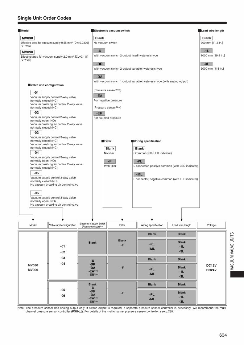
Single Unit Order Codes
Note: The pressure sensor has analog output only. If switch output is required, a separate pressure sensor controller is necessary. We recommend the multi-channel pressure sensor controller (PSU-□). For details of the multi-channel pressure sensor controller, see p.780.
Blank
-PL-ML
FilterElectronic Vacuum Switch(Pressure sensor)Note
Blank
Blank
-1L-3L
Lead wire length VoltageModel Valve unit configuration Wiring specification
■Model
■Valve unit configuration
■Filter
■Lead wire length
■Wiring specification
■Electronic vacuum switch
-DRWith vacuum switch 2-output variable hysteresis type
-DAWith vacuum switch 1-output variable hysteresis type (with analog output)
(Pressure sensor Note)
(Pressure sensor Note)
-EAFor negative pressure
-ERFor coupled pressure
Blank
-PL-ML
Blank
Blank
-1L-3L
Blank
-PL-ML
Blank
Blank
-1L-3L
Blank
-D-DR-DA
-EANote
-ERNote
Blank-D
-DR-DA
-EANote
-ERNote
MV030MV090
-01
-02
-03
-04
-05
-06
DC12VDC24V
Blank
-F
-F
-F
MV030Effective area for vacuum supply 0.55 mm2 [Cv=0.0306] (V→VS)
MV090Effective area for vacuum supply 2.0 mm2 [Cv=0.111](V→VS)
-01Vacuum supply control 2-way valve normally closed (NC)Vacuum breaking air control 2-way valvenormally closed (NC)
-02Vacuum supply control 2-way valve normally open (NO)Vacuum breaking air control 2-way valvenormally closed (NC)
-03Vacuum supply control 3-way valve normally closed (NC)Vacuum breaking air control 2-way valvenormally closed (NC)
-04Vacuum supply control 3-way valve normally open (NO)Vacuum breaking air control 2-way valvenormally closed (NC)
-05Vacuum supply control 3-way valvenormally closed (NC)No vacuum breaking air control valve
-06Vacuum supply control 3-way valvenormally open (NO)No vacuum breaking air control valve
BlankNo vacuum switch
-DWith vacuum switch 2-output fixed hysteresis type
BlankNo filter
-FWith filter
BlankGrommet (with LED indicator)
-PLL connector, positive common (with LED indicator)
-MLL connector, negative common (with LED indicator)
Blank300 mm [11.8 in.]
-1L1000 mm [39.4 in.]
-3L3000 mm [118 in.]
635
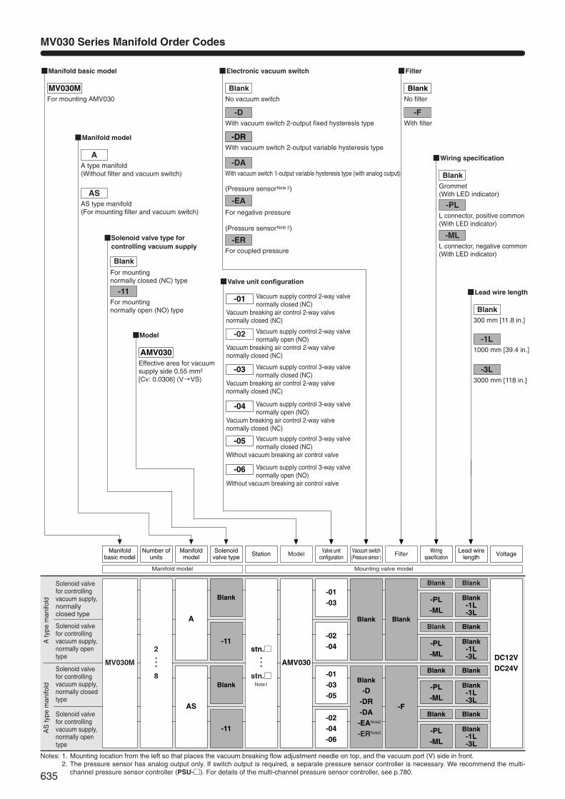
MV030 Series Manifold Order Codes
Notes: 1. Mounting location from the left so that places the vacuum breaking flow adjustment needle on top, and the vacuum port (V) side in front.2. The pressure sensor has analog output only. If switch output is required, a separate pressure sensor controller is necessary. We recommend the multi-
channel pressure sensor controller (PSU-□). For details of the multi-channel pressure sensor controller, see p.780.
Blank
-PL-ML
ModelManifoldmodel
Solenoidvalve type Station
Blank
Blank -1L-3L
Filter VoltageManifoldbasic model
Number ofunits
Valve unitconfiguration
Vacuum switch(Pressure sensor )
Wiringspecification
Lead wirelength
■Manifold basic model
■Valve unit configuration
MV030MFor mounting AMV030
■Model
AMV030Effective area for vacuumsupply side 0.55 mm2
[Cv: 0.0306] (V→VS)
■Manifold model
■Filter
■Lead wire length
■Wiring specification
■Electronic vacuum switch
■Solenoid valve type forcontrolling vacuum supply
-DRWith vacuum switch 2-output variable hysteresis type
-DAWith vacuum switch 1-output variable hysteresis type (with analog output)
-EA
(Pressure sensorNote 2)
(Pressure sensorNote 2)
For negative pressure
-ERFor coupled pressure
Blank
-PL-ML
Blank
Blank-1L-3L
Blank
-PL-ML
Blank
Blank -1L-3L
Blank
-PL-ML
Blank
Blank -1L-3L
Blank
-11
Blank
-11
-01-03
-02-04
-01-03-05
-02-04-06
Blank
Blank
-D-DR-DA-EANote2
-ERNote2
MV030M AMV030
stn.□・・・
stn.□Note1
2・・・8
A
AS
DC12VDC24V
Blank
-F
Manifold model Mounting valve model
AA type manifold(Without filter and vacuum switch)
ASAS type manifold(For mounting filter and vacuum switch)
Blank
For mounting normally closed (NC) type
-11For mounting normally open (NO) type
BlankNo vacuum switch
-DWith vacuum switch 2-output fixed hysteresis type
Vacuum supply control 2-way valvenormally closed (NC)
Vacuum breaking air control 2-way valvenormally closed (NC)
Vacuum supply control 2-way valvenormally open (NO)
Vacuum breaking air control 2-way valvenormally closed (NC)
Vacuum supply control 3-way valvenormally closed (NC)
Vacuum breaking air control 2-way valvenormally closed (NC)
Vacuum supply control 3-way valvenormally open (NO)
Vacuum breaking air control 2-way valvenormally closed (NC)
Vacuum supply control 3-way valvenormally closed (NC)
Without vacuum breaking air control valve
Vacuum supply control 3-way valvenormally open (NO)
Without vacuum breaking air control valve
-02
-01
-03
-04
-05
-06
BlankNo filter
-FWith filter
BlankGrommet(With LED indicator)
-PLL connector, positive common(With LED indicator)
-MLL connector, negative common(With LED indicator)
Blank300 mm [11.8 in.]
-1L1000 mm [39.4 in.]
-3L3000 mm [118 in.]
Aty
pem
anifo
ld
Solenoid valvefor controllingvacuum supply,normallyclosed type
Solenoid valvefor controllingvacuum supply,normally opentype
AS
type
man
ifold
Solenoid valvefor controllingvacuum supply,normally closedtype
Solenoid valvefor controllingvacuum supply,normally opentype
636
VACU
UM V
ALVE
UNI
TS
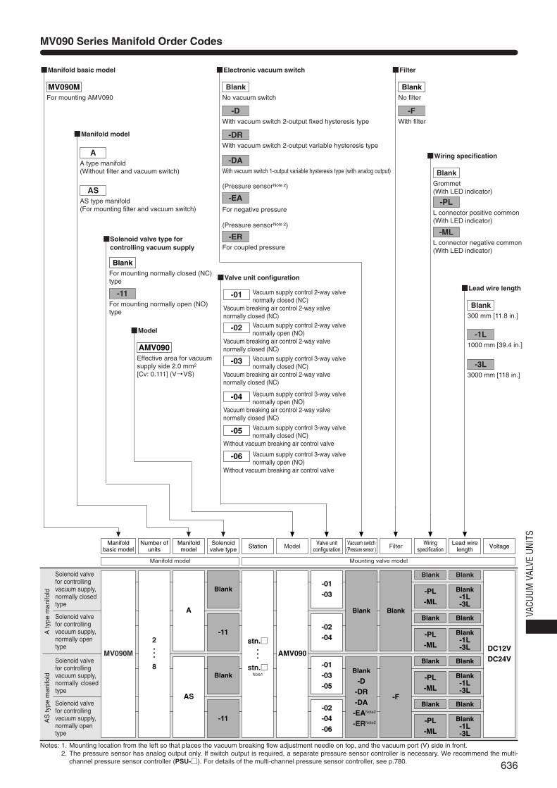
MV090 Series Manifold Order Codes
Notes: 1. Mounting location from the left so that places the vacuum breaking flow adjustment needle on top, and the vacuum port (V) side in front.2. The pressure sensor has analog output only. If switch output is required, a separate pressure sensor controller is necessary. We recommend the multi-
channel pressure sensor controller (PSU-□). For details of the multi-channel pressure sensor controller, see p.780.
Blank
-PL-ML
ModelManifoldmodel
Solenoidvalve type Station
Blank
Blank-1L-3L
Filter VoltageManifoldbasic model
Number ofunits
Valve unitconfiguration
Vacuum switch(Pressure sensor )
Wiringspecification
Lead wirelength
■Manifold basic model
■Valve unit configuration
MV090MFor mounting AMV090
■Model
AMV090Effective area for vacuumsupply side 2.0 mm2
[Cv: 0.111] (V→VS)
■Manifold model
■Filter
■Lead wire length
■Wiring specification
■Electronic vacuum switch
Blank
-PL-ML
Blank
Blank-1L-3L
Blank
-PL-ML
Blank
Blank-1L-3L
Blank
-PL-ML
Blank
Blank-1L-3L
Blank
-11
Blank
-11
-01-03
-02-04
-01-03-05
-02-04-06
Blank
Blank
-D-DR-DA-EANote2
-ERNote2
MV090M AMV090
stn.□・・・
stn.□Note1
2・・・8
A
AS
DC12VDC24V
Blank
-F
Manifold model Mounting valve model
AA type manifold(Without filter and vacuum switch)
ASAS type manifold(For mounting filter and vacuum switch)
■Solenoid valve type forcontrolling vacuum supply
BlankFor mounting normally closed (NC)type
-11For mounting normally open (NO)type
-DRWith vacuum switch 2-output variable hysteresis type
-DAWith vacuum switch 1-output variable hysteresis type (with analog output)
-EA
(Pressure sensorNote 2)
(Pressure sensorNote 2)
For negative pressure
-ERFor coupled pressure
BlankNo vacuum switch
-DWith vacuum switch 2-output fixed hysteresis type
Vacuum supply control 2-way valvenormally closed (NC)
Vacuum breaking air control 2-way valvenormally closed (NC)
Vacuum supply control 2-way valvenormally open (NO)
Vacuum breaking air control 2-way valvenormally closed (NC)
Vacuum supply control 3-way valvenormally closed (NC)
Vacuum breaking air control 2-way valvenormally closed (NC)
Vacuum supply control 3-way valvenormally open (NO)
Vacuum breaking air control 2-way valvenormally closed (NC)
Vacuum supply control 3-way valvenormally closed (NC)
Without vacuum breaking air control valve
Vacuum supply control 3-way valvenormally open (NO)
Without vacuum breaking air control valve
-01
-02
-03
-04
-05
-06
BlankNo filter
-FWith filter
BlankGrommet(With LED indicator)
-PLL connector positive common(With LED indicator)
-MLL connector negative common(With LED indicator)
Blank300 mm [11.8 in.]
-1L1000 mm [39.4 in.]
-3L3000 mm [118 in.]
Aty
pem
anifo
ld
Solenoid valvefor controllingvacuum supply,normally closedtype
Solenoid valvefor controllingvacuum supply,normally opentype
AS
type
man
ifold
Solenoid valvefor controllingvacuum supply,normally closedtype
Solenoid valvefor controllingvacuum supply,normally opentype
637
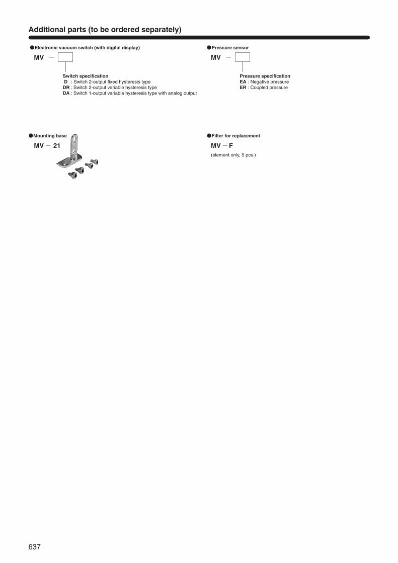
MV
Switch specificationD : Switch 2-output fixed hysteresis typeDR : Switch 2-output variable hysteresis typeDA : Switch 1-output variable hysteresis type with analog output
●Electronic vacuum switch (with digital display)
- MV
Pressure specificationEA : Negative pressureER : Coupled pressure
●Pressure sensor
-
MV F(element only, 5 pcs.)
●Filter for replacement
-MV 21
●Mounting base
-
Additional parts (to be ordered separately)
638
VACU
UM V
ALVE
UNI
TS
6.1 [0.240]
10 [0.394]
2-M2.6×0.45through Mounting hole
45 [1
.772
]
20 [0
.787
]
9 [0
.354
]
5 [0.197] (P, V port position)
Adjusting needle for vacuum breaking flow
Solenoid valve for controlling vacuum breaking air
Solenoid valve for controlling vacuum supply
67 [2
.638
]
10[0
.394
]4
[0.1
57] 5 [0.197]
33.6 [1.323]
M5×0.8 (V: Vacuum port)
4.7 [0.185] (VS port position)
MA
X. 1
5 [0
.591
]M
IN. 1
4 [0
.551
]55
[2.1
65]
P
R
VS
V
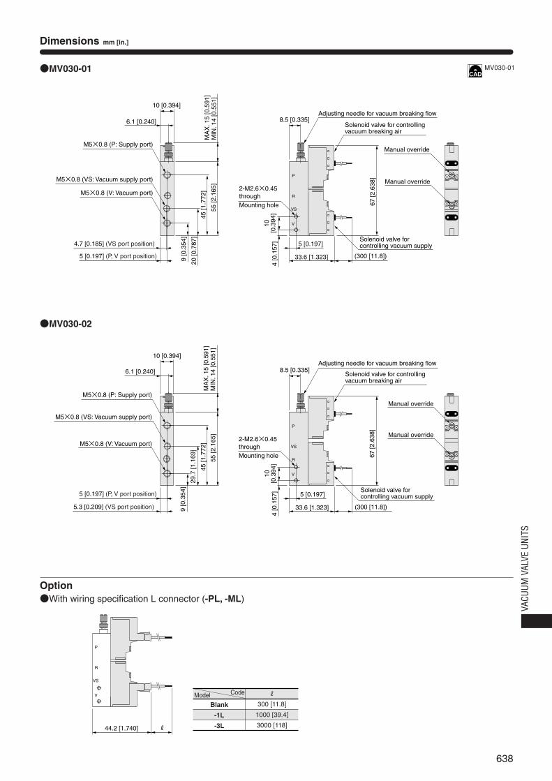
●MV030-01
●MV030-02
Option●With wiring specification L connector (-PL, -ML)
P
R
VS
V
Manual override
8.5 [0.335]
(300 [11.8])
M5×0.8 (VS: Vacuum supply port)
M5×0.8 (P: Supply port)
Manual override
44.2 [1.740] R
6.1 [0.240]
10 [0.394]
2-M2.6×0.45through Mounting hole
45 [1
.772
]
29.7
[1.1
69]
9 [0
.354
]
5 [0.197] (P, V port position)
Adjusting needle for vacuum breaking flow
Solenoid valve for controlling vacuum breaking air
Solenoid valve for controlling vacuum supply
67 [2
.638
]
10[0
.394
]4
[0.1
57] 5 [0.197]
33.6 [1.323]
M5×0.8 (V: Vacuum port)
5.3 [0.209] (VS port position)
MA
X. 1
5 [0
.591
]M
IN. 1
4 [0
.551
]55
[2.1
65]
P
R
VS
V
Manual override
8.5 [0.335]
(300 [11.8])
M5×0.8 (VS: Vacuum supply port)
M5×0.8 (P: Supply port)
Manual override
Dimensions mm [in.]
MV030-01
Model
Blank
-1L
-3L
Code R
300 [11.8]
1000 [39.4]
3000 [118]
639
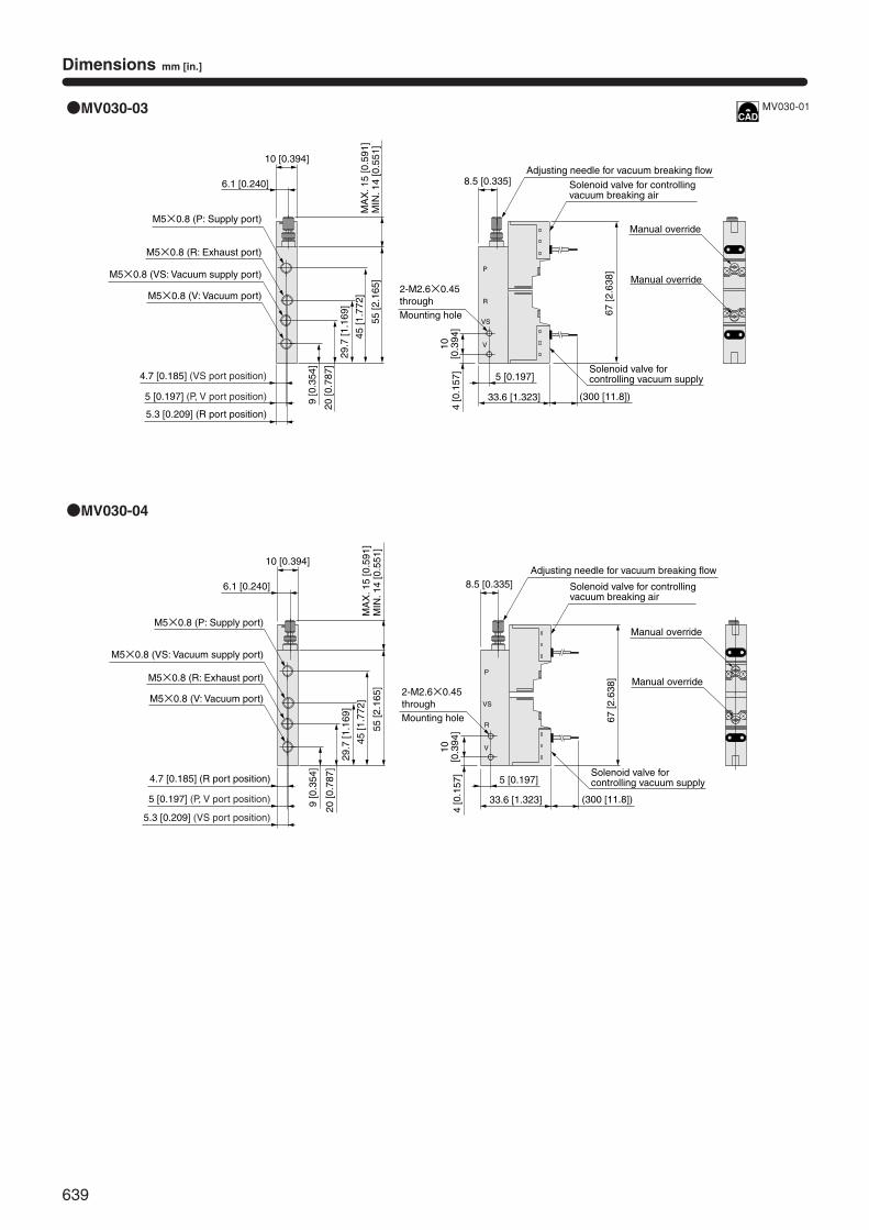
Dimensions mm [in.]
6.1 [0.240]
P
R
VS
V
●MV030-03
●MV030-04
4.7 [0.185] (R port position)
P
R
VS
V
M5×0.8 (R: Exhaust port)
6.1 [0.240]
10 [0.394]
5 [0.197] (P, V port position)
M5×0.8 (V: Vacuum port)
5.3 [0.209] (VS port position)
MA
X. 1
5 [0
.591
]M
IN. 1
4 [0
.551
]
M5×0.8 (VS: Vacuum supply port)
M5×0.8 (P: Supply port)
5.3 [0.209] (R port position)
5 [0.197] (P, V port position)
4.7 [0.185] (VS port position)
20 [0
.787
]
9 [0
.354
]
55 [2
.165
]
45 [1
.772
]
29.7
[1.1
69]
M5×0.8 (R: Exhaust port)
10 [0.394]
M5×0.8 (V: Vacuum port)
MA
X. 1
5 [0
.591
]M
IN. 1
4 [0
.551
]
M5×0.8 (VS: Vacuum supply port)
M5×0.8 (P: Supply port)
20 [0
.787
]
9 [0
.354
]
55 [2
.165
]
45 [1
.772
]
29.7
[1.1
69]
2-M2.6×0.45through Mounting hole
Adjusting needle for vacuum breaking flow
Solenoid valve for controlling vacuum breaking air
67 [2
.638
]
10[0
.394
]4
[0.1
57]
5 [0.197]
33.6 [1.323]
Manual override
8.5 [0.335]
(300 [11.8])
Manual override
Solenoid valve for controlling vacuum supply
Solenoid valve for controlling vacuum supply
2-M2.6×0.45through Mounting hole
Adjusting needle for vacuum breaking flow
Solenoid valve for controlling vacuum breaking air
67 [2
.638
]
10[0
.394
]4
[0.1
57]
5 [0.197]
33.6 [1.323]
Manual override
8.5 [0.335]
(300 [11.8])
Manual override
MV030-01

640
VACU
UM V
ALVE
UNI
TS
Dimensions mm [in.]
●MV030-01-□-F
●MV030-02-□-F
P
R
VS
44.2 [1.740] R
●Cable length of electronic vacuum switch (-DR)
16.1 [0.634]
Filter
20 [0.787]
5 [0.197]
V 45 [1
.772
]
20 [0
.787
]
6.5
[0.2
56]
14.7 [0.579] (VS port position)55
[2.1
65]
76 [2
.992
]
P
R
VS
48 [1.890]
Sealed cover Note 2
P1M
V-D
R
P2
kPa
KO
GA
NE
I
V
P
VS
R
P1M
V-D
R
P2
kPa
KO
GA
NE
I
k76
Electronic vacuum switch (-DR) Note 1
(with digital display)
M5×0.8(VS: Vacuum supply port)
M5×0.8(P: Supply port)
M5×0.8(V: Vacuum port)
15 [0.591] (P port position)
MA
X. 1
5 [0
.591
]M
IN. 1
4 [0
.551
]
2-M2.6×0.45Thread depth 4 [0.157] Mounting hole
Adjusting needle for vacuum breaking flow
Solenoid valve for controlling vacuum breaking air
10[0
.394
]4
[0.1
57]
5 [0.197]
33.6 [1.323]
Manual override
8.5[0.335]
(300 [11.8])
Manual override
Solenoid valve for controlling vacuum supply
Solenoid valve for controlling vacuum supply
Filter
Sealed cover Note 2
Electronic vacuum switch (-DR) Note 1
(with digital display)
M5×0.8(VS: Vacuum supply port)
M5×0.8(P: Supply port)
5 [0.197]
14.7 [0.579] (VS port position)
M5×0.8(V: Vacuum port)
15 [0.591] (P port position)
16.1 [0.634]
20 [0.787]
45 [1
.772
]
20 [0
.787
]6.
5 [0
.256
]
55 [2
.165
]M
AX
. 15
[0.5
91]
MIN
. 14
[0.5
51]
76 [2
.992
]
48 [1.890]
2-M2.6×0.45Thread depth 4 [0.157] Mounting hole
Adjusting needle for vacuum breaking flow
Solenoid valve for controlling vacuum breaking air
10[0
.394
]4
[0.1
57] 5 [0.197]
33.6 [1.323]
8.5[0.335]
(300 [11.8])
Manual override
Manual override
Option●With L connector wiring specification (-PL, -ML)
Notes: 1. The electronic vacuum switch (-DR) comes with a cable with connector.2. For cases without electronic vacuum switch
Notes: 1. The electronic vacuum switch (-DR) comes with a cable with connector.2. For cases without electronic vacuum switch
Model (wiring specifications and lead wire length)
-PL-Blank, -PL-1L-ML-Blank, -ML-1L
-PL-3L, -ML-3L
Code k
1500 [59]
3000 [118]
Model
Blank
-1L
-3L
Code R
300 [11.8]
1000 [39.4]
3000 [118]
641
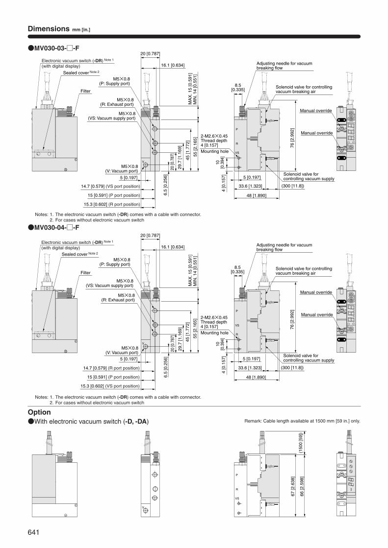
Dimensions mm [in.]
●MV030-03-□-F
●MV030-04-□-F
Option●With electronic vacuum switch (-D, -DA)
V
P
R
VS
29.7
[1.1
69]
P1
MV-DR
P2
kPa
KOGANEI
V
P
VS
R
P1
MV-DR
P2
kPa
KOGANEI
V
67 [2
.638
]
66 [2
.598
]P
R
VS
(150
0 [5
9])
Filter
Sealed cover Note 2
Electronic vacuum switch (-DR) Note 1
(with digital display)
M5×0.8(VS: Vacuum supply port)
M5×0.8(P: Supply port)
M5×0.8(R: Exhaust port)
M5×0.8(V: Vacuum port)
5 [0.197]
14.7 [0.579] (VS port position)
15 [0.591] (P port position)
15.3 [0.602] (R port position)
45 [1
.772
]
20 [0
.787
]
6.5
[0.2
56]
55 [2
.165
]M
AX
. 15
[0.5
91]
MIN
. 14
[0.5
51]
16.1 [0.634]
20 [0.787]
2-M2.6×0.45Thread depth 4 [0.157] Mounting hole
8.5[0.335]
48 [1.890]
10[0
.394
]4
[0.1
57]
5 [0.197]
33.6 [1.323] (300 [11.8])
Solenoid valve for controlling vacuum supply
Solenoid valve for controlling vacuum supply
76 [2
.992
]
Adjusting needle for vacuum breaking flow
Solenoid valve for controlling vacuum breaking air
Manual override
Manual override
Manual override
Manual override
Filter
Sealed cover Note 2
Electronic vacuum switch (-DR) Note 1
(with digital display)
M5×0.8(VS: Vacuum supply port)
M5×0.8(P: Supply port)
M5×0.8(R: Exhaust port)
M5×0.8(V: Vacuum port)
5 [0.197]
14.7 [0.579] (R port position)
15 [0.591] (P port position)
15.3 [0.602] (VS port position)
29.7
[1.1
69]
45 [1
.772
]
20 [0
.787
]
6.5
[0.2
56]
55 [2
.165
]M
AX
. 15
[0.5
91]
MIN
. 14
[0.5
51]
16.1 [0.634]
20 [0.787]
2-M2.6×0.45Thread depth 4 [0.157] Mounting hole
8.5[0.335]
10[0
.394
]4
[0.1
57]
48 [1.890]
5 [0.197]
33.6 [1.323] (300 [11.8])
76 [2
.992
]
Adjusting needle for vacuum breaking flow
Solenoid valve for controlling vacuum breaking air
Notes: 1. The electronic vacuum switch (-DR) comes with a cable with connector.2. For cases without electronic vacuum switch
Notes: 1. The electronic vacuum switch (-DR) comes with a cable with connector.2. For cases without electronic vacuum switch
Remark: Cable length available at 1500 mm [59 in.] only.
642
VACU
UM V
ALVE
UNI
TS
Dimensions mm [in.]
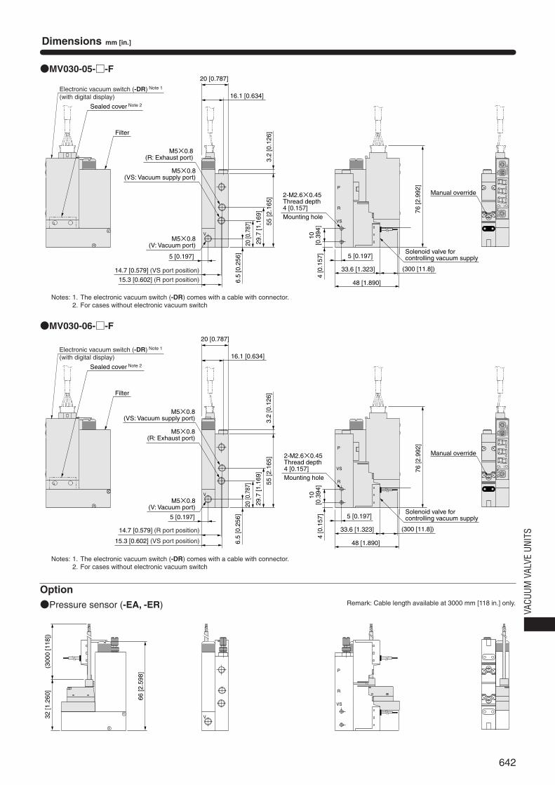
●MV030-05-□-F
●MV030-06-□-F
Option●Pressure sensor (-EA, -ER)
V
3.2
[0.1
26]
P
R
VS
P1
MV-DR
P2
kPa
KOGANEI
V
P
VS
R
P1
MV-DR
P2
kPa
KOGANEI
V
P
R
VS
32 [1
.260
]
66 [2
.598
]
(300
0 [1
18])
Filter
Sealed cover Note 2
Electronic vacuum switch (-DR) Note 1
(with digital display)
M5×0.8(VS: Vacuum supply port)
M5×0.8(R: Exhaust port)
16.1 [0.634]
20 [0.787]
M5×0.8(V: Vacuum port)
5 [0.197]
14.7 [0.579] (VS port position)
15.3 [0.602] (R port position)
29.7
[1.1
69]
20 [0
.787
]
6.5
[0.2
56]
55 [2
.165
] 2-M2.6×0.45Thread depth 4 [0.157] Mounting hole
10[0
.394
]4
[0.1
57]
48 [1.890]
5 [0.197]
33.6 [1.323] (300 [11.8])
Solenoid valve for controlling vacuum supply
76 [2
.992
]
Manual override
Manual override
Solenoid valve for controlling vacuum supply
Filter
Sealed cover Note 2
Electronic vacuum switch (-DR) Note 1
(with digital display)
M5×0.8(VS: Vacuum supply port)
M5×0.8(R: Exhaust port)
M5×0.8(V: Vacuum port)
5 [0.197]
14.7 [0.579] (R port position)
15.3 [0.602] (VS port position)
3.2
[0.1
26]
29.7
[1.1
69]
20 [0
.787
]
6.5
[0.2
56]
55 [2
.165
]
16.1 [0.634]
20 [0.787]
2-M2.6×0.45Thread depth 4 [0.157] Mounting hole
10[0
.394
]4
[0.1
57]
48 [1.890]
5 [0.197]
33.6 [1.323] (300 [11.8])
76 [2
.992
]
Notes: 1. The electronic vacuum switch (-DR) comes with a cable with connector.2. For cases without electronic vacuum switch
Notes: 1. The electronic vacuum switch (-DR) comes with a cable with connector.2. For cases without electronic vacuum switch
Remark: Cable length available at 3000 mm [118 in.] only.
643
Dimensions mm [in.]
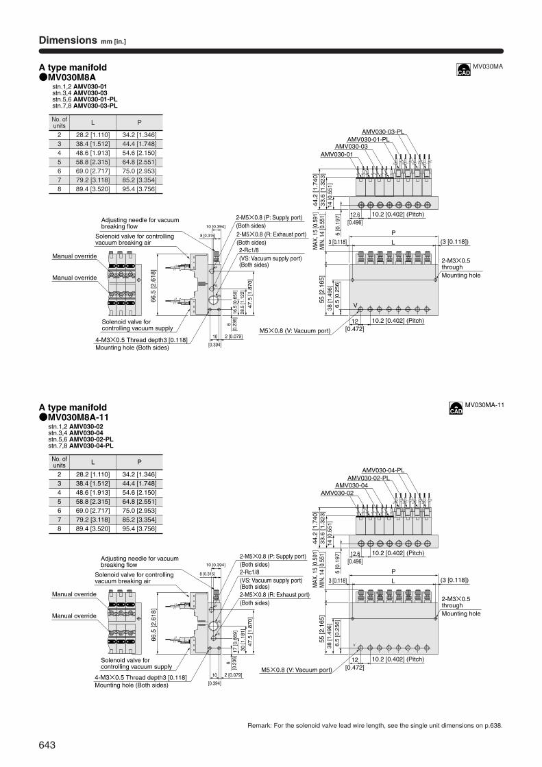
A type manifold
A type manifold
●MV030M8Astn.1,2 AMV030-01stn.3,4 AMV030-03stn.5,6 AMV030-01-PLstn.7,8 AMV030-03-PL
●MV030M8A-11stn.1,2 AMV030-02stn.3,4 AMV030-04stn.5,6 AMV030-02-PLstn.7,8 AMV030-04-PL
V
28.5
[1.1
22]
2-Rc1/8(VS: Vacuum supply port)(Both sides)
2-M5×0.8 (R: Exhaust port)(Both sides)
P
VS
R
47.5
[1.8
70]
66.5
[2.6
18]
10 [0.394]
4-M3×0.5 Thread depth3 [0.118]Mounting hole (Both sides)
38
[1.4
96]
6.5
[0.2
56]
55 [2
.165
]
2-M3×0.5throughMounting hole
12[0.472]
10.2 [0.402] (Pitch)
3 [0.118] L (3 [0.118])P
14 [0
.551
]5
[0.1
97]
33.6
[1.3
23]
44.2
[1.7
40]
AMV030-01AMV030-03
AMV030-01-PLAMV030-03-PL
12.6[0.496]
10.2 [0.402] (Pitch)
V
P
66.5
[2.6
18]
L
P
AMV030-02AMV030-04
AMV030-02-PLAMV030-04-PL
VS
R
Manual override
Manual override
Manual override
Manual override
Solenoid valve for controlling vacuum supply
Adjusting needle for vacuum breaking flow
Solenoid valve for controlling vacuum breaking air
2-M5×0.8 (P: Supply port)(Both sides)
MAX
. 15
[0.5
91]
MIN
. 14
[0.5
51]
M5×0.8 (V: Vacuum port)
4-M3×0.5 Thread depth3 [0.118]Mounting hole (Both sides)
Solenoid valve for controlling vacuum supply
Adjusting needle for vacuum breaking flow
Solenoid valve for controlling vacuum breaking air
8 [0.315]
10 [0.394]
8 [0.315]
10
[0.394]
2 [0.079]
2-Rc1/8(VS: Vacuum supply port)(Both sides)2-M5×0.8 (R: Exhaust port)(Both sides)
2-M5×0.8 (P: Supply port)(Both sides)
30 [1
.181
]
6[0
.236
]
47.5
[1.8
70]
M5×0.8 (V: Vacuum port)
14 [0
.551
]5
[0.1
97]
33.6
[1.3
23]
44.2
[1.7
40]
MAX
. 15
[0.5
91]
MIN
. 14
[0.5
51]
3 [0.118]
12.6[0.496]
10.2 [0.402] (Pitch)
2-M3×0.5throughMounting hole
(3 [0.118])
12[0.472]
10.2 [0.402] (Pitch)
38 [1
.496
]6.
5 [0
.256
]
55 [2
.165
]
17 [0
.669
]
10
[0.394]
2 [0.079]
6[0
.236
]16
.5 [0
.650
]
Remark: For the solenoid valve lead wire length, see the single unit dimensions on p.638.
MV030MA
MV030MA-11
No. ofunits
2345678
L
28.2 [1.110]38.4 [1.512]48.6 [1.913]58.8 [2.315]69.0 [2.717]79.2 [3.118]89.4 [3.520]
P
34.2 [1.346]44.4 [1.748]54.6 [2.150]64.8 [2.551]75.0 [2.953]85.2 [3.354]95.4 [3.756]
No. ofunits
2345678
L
28.2 [1.110]38.4 [1.512]48.6 [1.913]58.8 [2.315]69.0 [2.717]79.2 [3.118]89.4 [3.520]
P
34.2 [1.346]44.4 [1.748]54.6 [2.150]64.8 [2.551]75.0 [2.953]85.2 [3.354]95.4 [3.756]
644
VACU
UM V
ALVE
UNI
TS
Dimensions mm [in.]
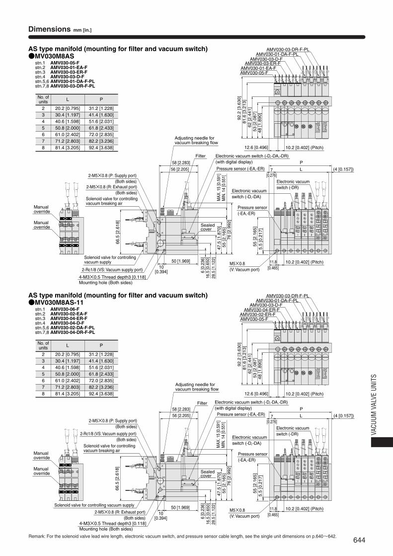
AS type manifold (mounting for filter and vacuum switch)●MV030M8AS
stn.1 AMV030-05-Fstn.2 AMV030-01-EA-Fstn.3 AMV030-03-ER-Fstn.4 AMV030-03-D-Fstn.5,6 AMV030-01-DA-F-PLstn.7,8 AMV030-03-DR-F-PL
AS type manifold (mounting for filter and vacuum switch)●MV030M8AS-11
stn.1 AMV030-06-Fstn.2 AMV030-02-EA-Fstn.3 AMV030-04-ER-Fstn.4 AMV030-04-D-Fstn.5,6 AMV030-02-DA-F-PLstn.7,8 AMV030-04-DR-F-PL
Manualoverride
Manualoverride
Manualoverride
Manualoverride
28.5
[1.1
22]
16.5
[0.6
50]
6 [0
.236
]Solenoid valve for controllingvacuum supply
Adjusting needle forvacuum breaking flow
Solenoid valve for controllingvacuum breaking air
P
VS
R
47.5
[1.8
70]
66.5
[2.6
18]
56 [2.205]
58 [2.283]
10[0.394]
50 [1.969]
55 [2
.165
]5.
5 [0
.217
]
55 [2.1
65]
76 [2.9
92]
11.8[0.465]
10.2 [0.402] (Pitch)M5×0.8(V: Vacuum port)
L (4 [0.157])
P
62 [2.4
41]
53 [2.0
87]
48 [1.8
90]
81.6
[3.2
13]
92.2
[3.6
30]
AMV030-01-EA-F
AMV030-03-D-FAMV030-01-DA-F-PL
AMV030-03-DR-F-PL
12.6 [0.496] 10.2 [0.402] (Pitch)
Filter
AMV030-05-F
AMV030-03-ER-F
KO
GA
NE
I
kPa
P2
MV
-DRP1
KO
GA
NE
I
kPa
P2
MV
-DRP1
Electronic vacuum switch (-D,-DA,-DR)(with digital display)
Sealedcover
Pressure sensor (-EA,-ER)
Pressure sensor(-EA,-ER)
Electronic vacuumswitch (-D,-DA)
Electronic vacuumswitch (-DR)
P
L
P
AMV030-02-ER-F
AMV030-03-D-FAMV030-01-DA-F-PL
AMV030-03-DR-F-PL
AMV030-05-F
AMV030-04-ER-F
KOGANEI
kPa
P2
MV-DRP1
KOGANEI
kPa
P2
MV-DRP1
VS
R
2-Rc1/8 (VS: Vacuum supply port)
2-M5×0.8 (R: Exhaust port)(Both sides)
2-M5×0.8 (P: Supply port)(Both sides)
4-M3×0.5 Thread depth3 [0.118]Mounting hole (Both sides)
MAX
. 15
[0.5
91]
MIN
. 14
[0.5
51]
7[0.276]
Solenoid valve for controlling vacuum supply
Solenoid valve for controllingvacuum breaking air
2-Rc1/8 (VS: Vacuum supply port)(Both sides)
2-M5×0.8 (R: Exhaust port)(Both sides)
2-M5×0.8 (P: Supply port)(Both sides)
4-M3×0.5 Thread depth3 [0.118]Mounting hole (Both sides)
66.5
[2.6
18]
10[0.394]
50 [1.969]
Adjusting needle forvacuum breaking flow
56 [2.205]58 [2.283]
Filter Electronic vacuum switch (-D,-DA,-DR)(with digital display)Pressure sensor (-EA,-ER)
MAX
. 15
[0.5
91]
MIN
. 14
[0.5
51]
62 [2.4
41]
53 [2.0
87]
48 [1.8
90]
81.6
[3.2
13]
92.2
[3.6
30]
12.6 [0.496] 10.2 [0.402] (Pitch)
(4 [0.157])
Pressure sensor(-EA,-ER)
Electronic vacuumswitch (-D,-DA)
Electronic vacuumswitch (-DR)
7[0.276]
55 [2
.165
]5.
5 [0
.217
]
11.8[0.465]
10.2 [0.402] (Pitch)M5×0.8(V: Vacuum port)
28.5
[1.1
22]
16.5
[0.6
50]
6 [0
.236
]
47.5
[1.8
70]
55 [2.1
65]
76 [2.9
92]
Sealedcover
Remark: For the solenoid valve lead wire length, electronic vacuum switch, and pressure sensor cable length, see the single unit dimensions on p.640~642.
No. ofunits
2345678
L
20.2 [0.795]30.4 [1.197]40.6 [1.598]50.8 [2.000]61.0 [2.402]71.2 [2.803]81.4 [3.205]
P
31.2 [1.228]41.4 [1.630]51.6 [2.031]61.8 [2.433]72.0 [2.835]82.2 [3.236]92.4 [3.638]
No. ofunits
2345678
L
20.2 [0.795]30.4 [1.197]40.6 [1.598]50.8 [2.000]61.0 [2.402]71.2 [2.803]81.4 [3.205]
P
31.2 [1.228]41.4 [1.630]51.6 [2.031]61.8 [2.433]72.0 [2.835]82.2 [3.236]92.4 [3.638]
645
Dimensions mm [in.]
25 [0.984]
10[0.394]
10.5[0.413]
10[0
.394
]
6 [0
.236
]
4 [0.157] φ3.6 [0.142]
2.8 [0.110]R1.8 [0.071]
R1.4 [0.055]
1.6
[0.0
63]
10 [0
.394
]
23 [0
.906
]
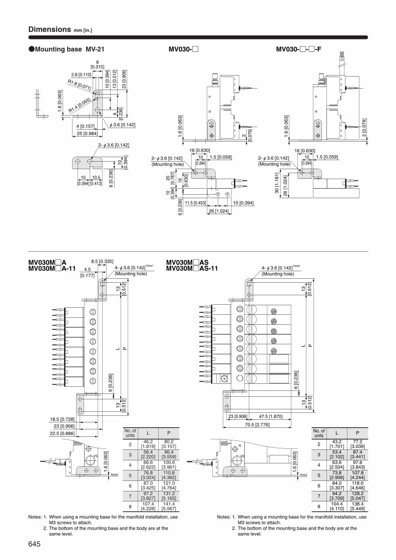
●Mounting base MV-21
13 [0
.512
]
8[0.315]
2-φ3.6 [0.142]
P
R
VS
V
P
R
VS
MV030-□ MV030-□-□-F
1.5 [0.059]
26 [1.024]
16 [0.630]
10 [0.394]11.5 [0.453]
20[0
.787
]10
[0.3
94]
16[0
.630
]1.
6 [0
.063
]6
[0.2
36]
30 [1
.181
]
26 [1
.024
]
2[0
.079
]
2-φ3.6 [0.142](Mounting hole)
2-φ3.6 [0.142](Mounting hole)
1.6
[0.0
63]
P
VS
R
P
VS
R
MV030M□AMV030M□A-11
MV030M□ASMV030M□AS-114.5
[0.177]
8.5 [0.335]
13[0
.512
]
18.5 [0.728]
6 [0
.236
]
13[0
.512
]PL
23 [0.906]
PL
23 [0.906]
22.5 [0.886]
4-φ3.6 [0.142] Note1
(Mounting hole)
1.6
[0.0
63]
Note2
70.5 [2.776]
47.5 [1.870]
6[0
.236
]
10[0.394]
2 [0
.079
]
1.5 [0.059]16 [0.630]
10[0.394]
4-φ3.6 [0.142] Note1
(Mounting hole)
13[0
.512
]
6 [0
.236
]
13[0
.512
]
1.6
[0.0
63]
Note2
No. ofunits
2
3
4
5
6
7
8
L
46.2[1.819]56.4
[2.220]66.6
[2.622]76.8
[3.024]87.0
[3.425]97.2
[3.827]107.4[4.228]
P
80.2[3.157]90.4
[3.559]100.6[3.961]110.8
[4.362]121.0[4.764]131.2[5.165]141.4[5.567]
No. ofunits
2
3
4
5
6
7
8
L
43.2[1.701]53.4
[2.102]63.6
[2.504]73.8
[2.906]84.0
[3.307]94.2
[3.709]104.4[4.110]
P
77.2[3.039]87.4
[3.441]97.6
[3.843]107.8[4.244]118.0
[4.646]128.2[5.047]138.4[5.449]
Notes: 1. When using a mounting base for the manifold installation, useM3 screws to attach.
2. The bottom of the mounting base and the body are at thesame level.
Notes: 1. When using a mounting base for the manifold installation, useM3 screws to attach.
2. The bottom of the mounting base and the body are at thesame level.
646
VACU
UM V
ALVE
UNI
TS
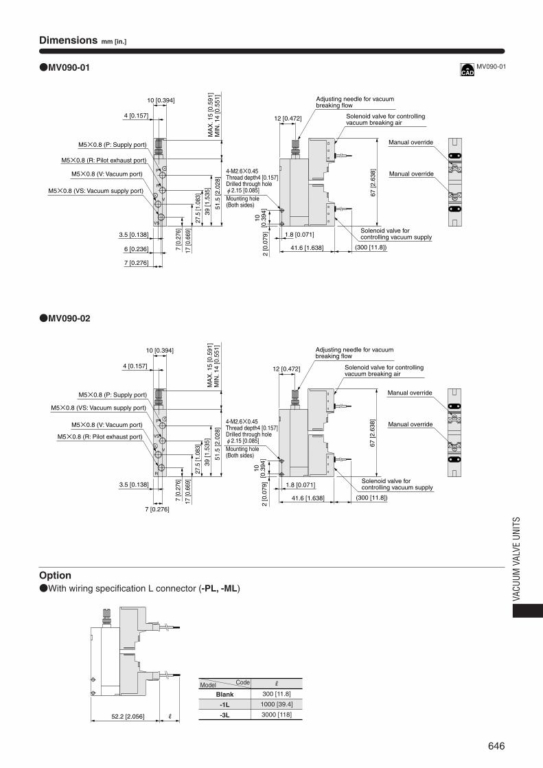
Dimensions mm [in.]
3.5 [0.138]
6 [0.236]
7 [0.276]
P
VS
R
V
●MV090-01
●MV090-02
4 [0.157]
10 [0.394]
39 [1
.535
]
17 [0
.669
]
7 [0
.276
]
67 [2
.638
]
10[0
.394
]2
[0.0
79] 1.8 [0.071]
41.6 [1.638]
51.5
[2.0
28]
(300 [11.8])
27.5
[1.0
83]
M5×0.8 (R: Pilot exhaust port)
R52.2 [2.056]
12 [0.472]
P
R
VS
V
Option●With wiring specification L connector (-PL, -ML)
MA
X. 1
5 [0
.591
]M
IN. 1
4 [0
.551
]M
AX
. 15
[0.5
91]
MIN
. 14
[0.5
51]
M5×0.8 (V: Vacuum port)
M5×0.8 (VS: Vacuum supply port)
M5×0.8 (P: Supply port)
4-M2.6×0.45Thread depth4 [0.157]Drilled through hole φ2.15 [0.085]Mounting hole(Both sides)
Adjusting needle for vacuumbreaking flow
Solenoid valve for controlling vacuum breaking air
Solenoid valve for controlling vacuum supply
Manual override
Manual override
M5×0.8 (R: Pilot exhaust port)
M5×0.8 (V: Vacuum port)
M5×0.8 (VS: Vacuum supply port)
M5×0.8 (P: Supply port)
4 [0.157]
10 [0.394]
39 [1
.535
]
17 [0
.669
]
7 [0
.276
]
51.5
[2.0
28]
27.5
[1.0
83]
3.5 [0.138]
7 [0.276]
4-M2.6×0.45Thread depth4 [0.157]Drilled through hole φ2.15 [0.085]Mounting hole(Both sides)
10[0
.394
]2
[0.0
79]
12 [0.472]
Adjusting needle for vacuumbreaking flow
Solenoid valve for controlling vacuum breaking air
Manual override
Manual override
67 [2
.638
]
1.8 [0.071]
41.6 [1.638] (300 [11.8])
Solenoid valve for controlling vacuum supply
MV090-01
Model
Blank
-1L
-3L
Code R
300 [11.8]
1000 [39.4]
3000 [118]
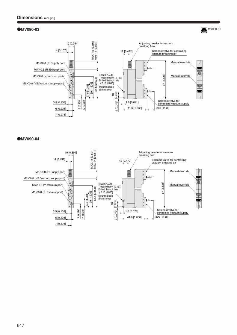
647
Dimensions mm [in.]
P
VS
R
V
●MV090-03
●MV090-04
P
R
VS
V
12 [0.472]
4 [0.157]
10 [0.394]
M5×0.8 (R: Exhaust port)
M5×0.8 (V: Vacuum port)
M5×0.8 (VS: Vacuum supply port)
M5×0.8 (P: Supply port)
MA
X. 1
5 [0
.591
]M
IN. 1
4 [0
.551
]
3.5 [0.138]
6 [0.236]
7 [0.276]
39 [1
.535
]
17 [0
.669
]
7 [0
.276
]
51.5
[2.0
28]
27.5
[1.0
83]
4-M2.6×0.45Thread depth4 [0.157]Drilled through hole φ2.15 [0.085]Mounting hole(Both sides)
10[0
.394
]2
[0.0
79]
1.8 [0.071]
41.6 [1.638]
12 [0.472]
(300 [11.8])
Solenoid valve for controlling vacuum supply
67 [2
.638
]
Adjusting needle for vacuumbreaking flow
Solenoid valve for controlling vacuum breaking air
Manual override
Manual override
4 [0.157]
10 [0.394]
M5×0.8 (R: Exhaust port)
M5×0.8 (V: Vacuum port)
M5×0.8 (VS: Vacuum supply port)
M5×0.8 (P: Supply port)
3.5 [0.138]
6 [0.236]
7 [0.276]
39 [1
.535
]
17 [0
.669
]
7 [0
.276
]
51.5
[2.0
28]
27.5
[1.0
83]
MA
X. 1
5 [0
.591
]M
IN. 1
4 [0
.551
]
4-M2.6×0.45Thread depth4 [0.157]Drilled through hole φ2.15 [0.085]Mounting hole(Both sides)
10[0
.394
]2
[0.0
79]
1.8 [0.071]
41.6 [1.638] (300 [11.8])
Solenoid valve for controlling vacuum supply
67 [2
.638
]
Adjusting needle for vacuumbreaking flow
Solenoid valve for controlling vacuum breaking air
Manual override
Manual override
MV090-01
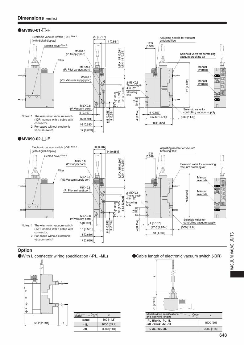
648
VACU
UM V
ALVE
UNI
TS
Dimensions mm [in.]
●MV090-01-□-F
●MV090-02-□-F
58.2 [2.291] R
P
R
VS
●Cable length of electronic vacuum switch (-DR)
17.5[0.689]
14 [0.551]
15 [0.591]
16 [0.630]
P
R
VSV
20 [0.787]
39
[1
.53
5]
9 [0
.354
]
51.5
[2.0
28]
13[0
.512
]4
[0.1
57]
4 [0.157]
(47.6 [1.874])
48 [1.890]
P1M
V-D
R
P2
kPa
KO
GA
NE
I
27
.5 [
1.0
83
]
17 [0.669]
P
VS
RV
P1
MV-DR
P2
kPa
KOGANEI
k76
[2.9
92]
Filter
Sealed cover Note 2
Electronic vacuum switch (-DR) Note 1
(with digital display)
M5×0.8(R: Pilot exhaust port)
M5×0.8(VS: Vacuum supply port)
M5×0.8(P: Supply port)
5 [0.197]
M5×0.8(V: Vacuum port)
6.5
[0.2
56]
MA
X. 1
5 [0
.591
]M
IN. 1
4 [0
.551
]
2-M3×0.5Thread depth 4 [0.157] Mountinghole
(300 [11.8])
Adjusting needle for vacuum breaking flow
Solenoid valve for controlling vacuum breaking air
Solenoid valve for controlling vacuum supply
76 [2
.992
]
Manualoverride
Manualoverride
Filter
Sealed cover Note 2
Electronic vacuum switch (-DR) Note 1
(with digital display)
M5×0.8(R: Pilot exhaust port)
M5×0.8(VS: Vacuum supply port)
M5×0.8(P: Supply port)
M5×0.8(V: Vacuum port)
14 [0.551]
20 [0.787]
MA
X. 1
5 [0
.591
]M
IN. 1
4 [0
.551
]
15 [0.591]
16 [0.630]
17 [0.669]
5 [0.197]
39
[1
.53
5]
9 [0
.354
]
51.5
[2.0
28]
27
.5 [
1.0
83
]
6.5
[0.2
56]
13[0
.512
]4
[0.1
57]
2-M3×0.5Thread depth 4 [0.157] Mountinghole
4 [0.157]
(47.6 [1.874])
48 [1.890]
(300 [11.8])
Solenoid valve for controlling vacuum supply
76 [2
.992
]
Manualoverride
Manualoverride
Adjusting needle for vacuum breaking flow
Solenoid valve for controlling vacuum breaking air
17.5[0.689]
Option●With L connector wiring specification (-PL, -ML)
Notes: 1. The electronic vacuum switch(-DR) comes with a cable withconnector.
2. For cases without electronicvacuum switch
Notes: 1. The electronic vacuum switch(-DR) comes with a cable withconnector.
2. For cases without electronicvacuum switch
Model
Blank
-1L
-3L
Code R
300 [11.8]
1000 [39.4]
3000 [118]
Model (wiring specifications and lead wire length)
-PL-Blank, -PL-1L-ML-Blank, -ML-1L
-PL-3L, -ML-3L
Code k
1500 [59]
3000 [118]
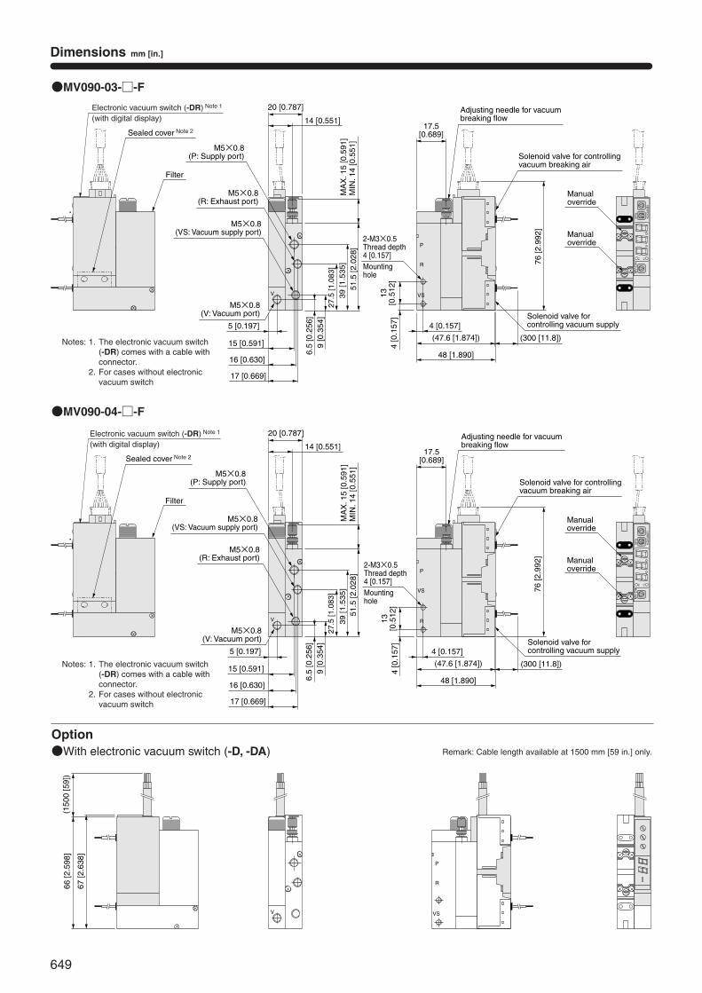
649
Dimensions mm [in.]
●MV090-03-□-F
●MV090-04-□-F
Option●With electronic vacuum switch (-D, -DA)
P
R
VSV
P1M
V-D
R
P2
kPa
KOGANEI
P
VS
RV
P1M
V-D
R
P2
kPa
KO
GA
NE
I
P
R
VSV
67 [2
.638
]
66 [2
.598
](1
500
[59]
)
Filter
Sealed cover Note 2
Electronic vacuum switch (-DR) Note 1
(with digital display)
M5×0.8(VS: Vacuum supply port)
M5×0.8(P: Supply port)
M5×0.8(R: Exhaust port)
M5×0.8(V: Vacuum port)
15 [0.591]
16 [0.630]
17 [0.669]
5 [0.197]
14 [0.551]
20 [0.787]
MA
X. 1
5 [0
.591
]M
IN. 1
4 [0
.551
]39 [1.5
35]
9 [0
.354
]
51.5
[2.0
28]
27.5
[1.0
83]
6.5
[0.2
56]
13[0
.512
]4
[0.1
57]
2-M3×0.5Thread depth 4 [0.157] Mountinghole
4 [0.157]
(47.6 [1.874])
48 [1.890]
(300 [11.8])
Solenoid valve for controlling vacuum supply
Adjusting needle for vacuum breaking flow
Solenoid valve for controlling vacuum breaking air
76 [2
.992
]
17.5[0.689]
Manualoverride
Manualoverride
Filter
Sealed cover Note 2
Electronic vacuum switch (-DR) Note 1
(with digital display)
M5×0.8(VS: Vacuum supply port)
M5×0.8(P: Supply port)
M5×0.8(R: Exhaust port)
M5×0.8(V: Vacuum port)
15 [0.591]
16 [0.630]
17 [0.669]
5 [0.197]
14 [0.551]
20 [0.787]
MA
X. 1
5 [0
.591
]M
IN. 1
4 [0
.551
]39 [1.5
35]
9 [0
.354
]
51.5
[2.0
28]
27.5
[1.0
83]
6.5
[0.2
56]
13[0
.512
]4
[0.1
57]
2-M3×0.5Thread depth 4 [0.157] Mountinghole
4 [0.157]
(47.6 [1.874])
48 [1.890]
(300 [11.8])
Solenoid valve for controlling vacuum supply
76 [2
.992
]
Adjusting needle for vacuum breaking flow
Solenoid valve for controlling vacuum breaking air
Manualoverride
Manualoverride
17.5[0.689]
Remark: Cable length available at 1500 mm [59 in.] only.
Notes: 1. The electronic vacuum switch(-DR) comes with a cable withconnector.
2. For cases without electronicvacuum switch
Notes: 1. The electronic vacuum switch(-DR) comes with a cable withconnector.
2. For cases without electronicvacuum switch
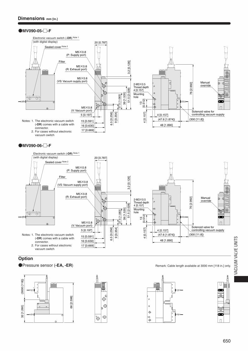
650
VACU
UM V
ALVE
UNI
TS
Dimensions mm [in.]
●MV090-05-□-F
●MV090-06-□-F
Option●Pressure sensor (-EA, -ER)
76 [2
.992
]
P
R
VSV
20 [0.787]
3.2
[0.1
26]
P1
MV-DR
P2
kPa
KOGANEI
P
VS
RV
3.2
[0.1
26]
P1M
V-D
R
P2
kPa
KO
GA
NE
I
P
R
VSV32 [1
.260
]
66 [2
.598
]
(300
0 [1
18])
Filter
Sealed cover Note 2
Electronic vacuum switch (-DR) Note 1
(with digital display)
M5×0.8(R: Exhaust port)
M5×0.8(VS: Vacuum supply port)
M5×0.8(P: Supply port)
M5×0.8(V: Vacuum port)
39 [1
.535
]
9 [0
.354
]
51.5
[2.0
28]
27.5
[1.0
83]
6.5
[0.2
56]
15 [0.591]
16 [0.630]
17 [0.669]
5 [0.197]
13[0
.512
]4
[0.1
57]
2-M3×0.5Thread depth 4 [0.157] Mountinghole
4 [0.157]
(47.6 [1.874])
48 [1.890]
(300 [11.8])
Solenoid valve for controlling vacuum supply
Manualoverride
Filter
Sealed cover Note 2
Electronic vacuum switch (-DR) Note 1
(with digital display)
M5×0.8(R: Exhaust port)
M5×0.8(VS: Vacuum supply port)
M5×0.8(P: Supply port)
M5×0.8(V: Vacuum port)
15 [0.591]
16 [0.630]
17 [0.669]
5 [0.197]
39 [1
.535
]
9 [0
.354
]
51.5
[2.0
28]
27.5
[1.0
83]
6.5
[0.2
56]
20 [0.787]
13[0
.512
]4
[0.1
57]
2-M3×0.5Thread depth 4 [0.157] Mountinghole
4 [0.157]
(47.6 [1.874])
48 [1.890]
76 [2
.992
]
(300 [11.8])
Solenoid valve for controlling vacuum supply
Manualoverride
Remark: Cable length available at 3000 mm [118 in.] only.
Notes: 1. The electronic vacuum switch(-DR) comes with a cable withconnector.
2. For cases without electronicvacuum switch
Notes: 1. The electronic vacuum switch(-DR) comes with a cable withconnector.
2. For cases without electronicvacuum switch
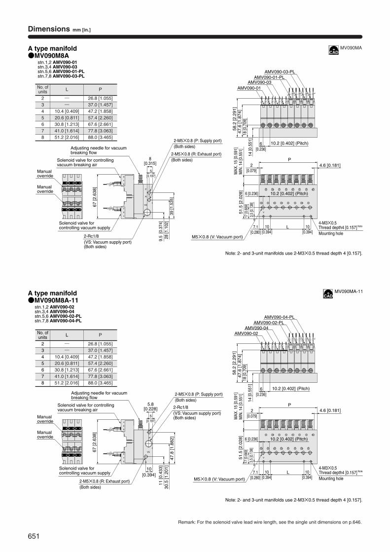
651
Dimensions mm [in.]
A type manifold
A type manifold
●MV090M8Astn.1,2 AMV090-01stn.3,4 AMV090-03stn.5,6 AMV090-01-PLstn.7,8 AMV090-03-PL
●MV090M8A-11stn.1,2 AMV090-02stn.3,4 AMV090-04stn.5,6 AMV090-02-PLstn.7,8 AMV090-04-PL
28 [1
.102
]9.
5 [0
.374
]
39 [1
.535
]
67 [2
.638
]
8[0.315]
17 [0
.669
]51
.5 [2
.028
]
4-M3×0.5Thread depth4 [0.157]
Note
Mounting hole
Note: 2- and 3-unit manifolds use 2-M3×0.5 thread depth 4 [0.157].
Note: 2- and 3-unit manifolds use 2-M3×0.5 thread depth 4 [0.157].
10.2 [0.402] (Pitch)
P
14 [0
.551
]18
[0.7
09]
47.6
[1.8
74]
58.2
[2.2
91]
AMV090-01AMV090-03
AMV090-01-PLAMV090-03-PL
6[0.236]
6 [0.236]
10.2 [0.402] (Pitch)
VS
R
P
V
7.1[0.280]
L10[0.394]
10[0.394]
2[0.079]
4.6 [0.181]30
.5 [1
.201
]11
[0.4
33]
47.8
[1.8
82]
67 [2
.638
]
5.8[0.228]
P
AMV090-02AMV090-04
AMV090-02-PLAMV090-04-PL
V
L
P
R
VS
10[0.394]
Manualoverride
Manualoverride
Adjusting needle for vacuum breaking flow
Solenoid valve for controlling vacuum breaking air
2-Rc1/8(VS: Vacuum supply port)(Both sides)
2-M5×0.8 (R: Exhaust port)(Both sides)
Solenoid valve for controlling vacuum supply
2-M5×0.8 (P: Supply port)(Both sides)
5[0.197]
MAX
. 15
[0.5
91]
MIN
. 14
[0.5
51]
3.5
[0.1
38]
M5×0.8 (V: Vacuum port)
Manualoverride
Manualoverride
Adjusting needle for vacuum breaking flow
Solenoid valve for controlling vacuum breaking air
5[0.197]
2-M5×0.8 (R: Exhaust port)(Both sides)
2-M5×0.8 (P: Supply port)(Both sides)
2-Rc1/8(VS: Vacuum supply port)(Both sides)
Solenoid valve for controlling vacuum supply
47.6
[1.8
74]
58.2
[2.2
91]
6[0.236]
10.2 [0.402] (Pitch)
14 [0
.551
]18
[0.7
09]
2[0.079]M
AX. 1
5 [0
.591
]M
IN. 1
4 [0
.551
]17
[0.6
69]
51.5
[2.0
28]
10.2 [0.402] (Pitch)6 [0.236]
7.1[0.280]
10[0.394]
3.5
[0.1
38]
M5×0.8 (V: Vacuum port)
4-M3×0.5Thread depth4 [0.157]
Note
Mounting hole10
[0.394]
4.6 [0.181]
Remark: For the solenoid valve lead wire length, see the single unit dimensions on p.646.
MV090MA
MV090MA-11
No. ofunits
2345678
L
――
10.4 [0.409]20.6 [0.811]30.8 [1.213]41.0 [1.614]51.2 [2.016]
P
26.8 [1.055]37.0 [1.457]47.2 [1.858]57.4 [2.260]67.6 [2.661]77.8 [3.063]88.0 [3.465]
No. ofunits
2345678
L
――
10.4 [0.409]20.6 [0.811]30.8 [1.213]41.0 [1.614]51.2 [2.016]
P
26.8 [1.055]37.0 [1.457]47.2 [1.858]57.4 [2.260]67.6 [2.661]77.8 [3.063]88.0 [3.465]
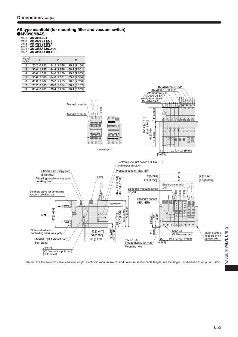
652
VACU
UM V
ALVE
UNI
TS
AMV090-01-EA-F
AMV090-03-D-FAMV090-01-DA-F-PL
AMV090-03-DR-F-PL
AS type manifold (for mounting filter and vacuum switch)●MV090M8AS
stn.1 AMV090-05-Fstn.2 AMV090-01-EA-Fstn.3 AMV090-03-ER-Fstn.4 AMV090-03-D-Fstn.5,6 AMV090-01-DA-F-PLstn.7,8 AMV090-03-DR-F-PL
AMV090-05-F
AMV090-03-ER-F
67 [2
.638
]
5.5
[0.2
17]
51.5
[2.0
28]
20[0.787]
7 [0.276] L (7 [0.276])P
66 [2
.598
]48
[1.8
90]
95.6
[3.7
64]
106.
2 [4
.181
]
11[0.433]
A
Viewed from A
63.5
[2.5
00]
13[0
.512
]
2.5 [0.098]
2.5
[0.0
98]
M (2.5 [0.098])
These mountingholes are on theopposite side.
KOGANEI
kPa
P2
MV-DRP1
KOGANEI
kPa
P2
MV-DRP1
27.5
[1.0
83]
9 [0
.354
]
40 [1.5
75]
58 [2.283]56 [2.205]52 [2.047]
P
R
VS
76 [2
.992
]
Pressure sensor(-EA, -ER)
Electronic vacuum switch (-D,-DA)
Electronic vacuum switch(-DR)
Pressure sensor (-EA, -ER)
Manual override
Manual override
2-M5×0.8 (P: Supply port)(Both sides)
Adjusting needle for vacuum breaking flow
Solenoid valve for controlling vacuum breaking air
Solenoid valve for controlling vacuum supply
2-Rc1/8(VS: Vacuum supply port)(Both sides)
2-M5×0.8 (R: Exhaust port)(Both sides)
Electronic vacuum switch (-D,-DA,-DR)(with digital display)
Filter
Sealed cover
MA
X. 1
5 [0
.591
]M
IN. 1
4 [0
.551
]
4-M3×0.5Thread depth3 [0.118] Mounting hole
10.2 [0.402] (Pitch)
M5×0.8(V: Vacuum port)
10.2 [0.402] (Pitch)14
[0.5
51]
Dimensions mm [in.]
Remark: For the solenoid valve lead wire length, electronic vacuum switch, and pressure sensor cable length, see the single unit dimensions on p.648~650.
No. ofunits
2345678
L
20.2 [0.795]30.4 [1.197]40.6 [1.598]50.8 [2.000]61.0 [2.402]71.2 [2.803]81.4 [3.205]
P
34.2 [1.346]44.4 [1.748]54.6 [2.150]64.8 [2.551]75.0 [2.953]85.2 [3.354]95.4 [3.756]
M
29.2 [1.150]39.4 [1.551]49.6 [1.953]59.8 [2.354]70.0 [2.756]80.2 [3.157]90.4 [3.559]
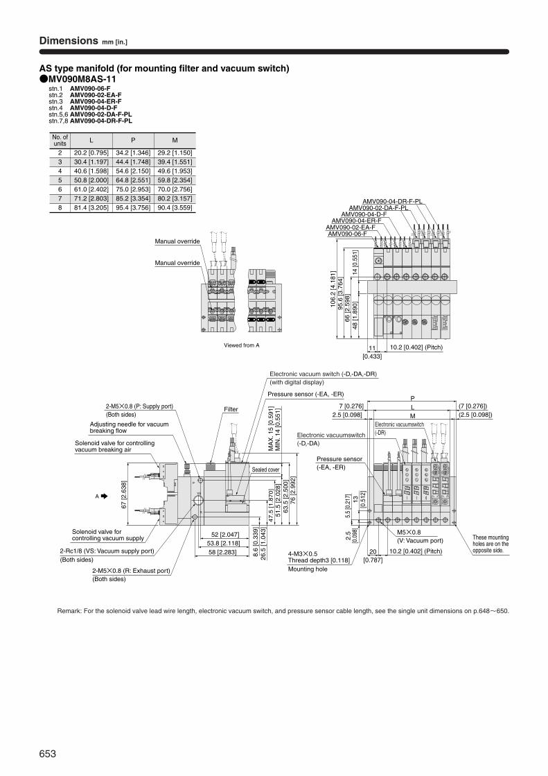
653
AS type manifold (for mounting filter and vacuum switch)●MV090M8AS-11
stn.1 AMV090-06-Fstn.2 AMV090-02-EA-Fstn.3 AMV090-04-ER-Fstn.4 AMV090-04-D-Fstn.5,6 AMV090-02-DA-F-PLstn.7,8 AMV090-04-DR-F-PL
LP
AMV090-02-EA-F
AMV090-04-D-FAMV090-02-DA-F-PL
AMV090-04-DR-F-PL
AMV090-06-F
AMV090-04-ER-F
A
M
R
VS
P
KOGANEI
kPa
P2
MV-DRP1
KOGANEI
kPa
P2
MV-DRP1
Viewed from A
Manual override
Manual override
66 [2
.598
]48
[1.8
90]
95.6
[3.7
64]
106.
2 [4
.181
]
11[0.433]
10.2 [0.402] (Pitch)14
[0.5
51]
2-M5×0.8 (P: Supply port)(Both sides)
Adjusting needle for vacuum breaking flow
Solenoid valve for controlling vacuum breaking air
67 [2
.638
]
Solenoid valve for controlling vacuum supply
2-M5×0.8 (R: Exhaust port)(Both sides)
2-Rc1/8 (VS: Vacuum supply port)(Both sides)
Pressure sensor (-EA, -ER)
Electronic vacuum switch (-D,-DA,-DR)(with digital display)
Filter
MA
X. 1
5 [0
.591
]M
IN. 1
4 [0
.551
]
58 [2.283]53.8 [2.118]
52 [2.047]
51.5
[2.0
28]
63.5
[2.5
00]
26.5
[1.0
43]
8.6
[0.3
39]
47.5
[1.8
70]
76 [2
.992
]
Sealed cover
7 [0.276] (7 [0.276])2.5 [0.098] (2.5 [0.098])
Pressure sensor(-EA, -ER)
Electronic vacuumswitch(-D,-DA)
Electronic vacuumswitch(-DR)
5.5
[0.2
17]
13[0
.512
]
2.5
[0.0
98]
4-M3×0.5Thread depth3 [0.118] Mounting hole
20[0.787]
These mountingholes are on theopposite side.10.2 [0.402] (Pitch)
M5×0.8(V: Vacuum port)
Dimensions mm [in.]
Remark: For the solenoid valve lead wire length, electronic vacuum switch, and pressure sensor cable length, see the single unit dimensions on p.648~650.
No. ofunits
2345678
L
20.2 [0.795]30.4 [1.197]40.6 [1.598]50.8 [2.000]61.0 [2.402]71.2 [2.803]81.4 [3.205]
P
34.2 [1.346]44.4 [1.748]54.6 [2.150]64.8 [2.551]75.0 [2.953]85.2 [3.354]95.4 [3.756]
M
29.2 [1.150]39.4 [1.551]49.6 [1.953]59.8 [2.354]70.0 [2.756]80.2 [3.157]90.4 [3.559]
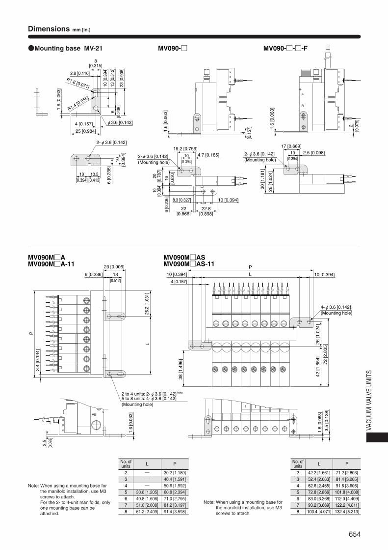
654
VACU
UM V
ALVE
UNI
TS
Dimensions mm [in.]
●Mounting base MV-21
VS
R
P
MV090M□AMV090M□A-11
MV090M□ASMV090M□AS-11
6 [0.236]
23 [0.906]
4 [0.157]
10 [0.394]10 [0.394] L
P
26.2
[1.0
31]
L 26 [1
.024
]
38 [1
.496
]
72 [2
.835
]
3.4
[0.1
34]
P
42 [1
.654
]
3.5
[0.1
38]
13[0.512]
2 to 4 units: 2-φ3.6 [0.142] Note
5 to 8 units: 4-φ3.6 [0.142](Mounting hole)
2.5
[0.0
98]
P
R
VS
MV090-□ MV090-□-□-F
22[0.866]
22.8[0.898]
4.7 [0.185]19.2 [0.756]
2.5 [0.098]17 [0.669]
2.8 [0.110]R1.8 [0.071]
R1.4 [0.055]
8[0.315]
25 [0.984]
4 [0.157]
1.6
[0.0
63]
φ3.6 [0.142]
10 [0
.394
]
23 [0
.906
]
13 [0
.512
]6
[0.2
36]
10[0.394]
10.5[0.413]
10[0
.394
]
6 [0
.236
]
2-φ3.6 [0.142]
1.6
[0.0
63]
4[0
.157
]
2-φ3.6 [0.142](Mounting hole)
2-φ3.6 [0.142](Mounting hole)
10[0.394]
10[0.394]
20[0
.787
]10
[0.3
94]
16[0
.630
]6
[0.2
36]
10 [0.394]8.3 [0.327]
30 [1
.181
]
26 [1
.024
]1.
6 [0
.063
]
2[0
.079
]
1.6
[0.0
63]
1.6
[0.0
63]
4-φ3.6 [0.142](Mounting hole)
Note: When using a mounting base forthe manifold installation, use M3screws to attach.For the 2- to 4-unit manifolds, onlyone mounting base can beattached.
Note: When using a mounting base forthe manifold installation, use M3screws to attach.
No. ofunits
2345678
L
―――
30.6 [1.205]40.8 [1.606]51.0 [2.008]61.2 [2.409]
P
30.2 [1.189]40.4 [1.591]50.6 [1.992]60.8 [2.394]71.0 [2.795]81.2 [3.197]91.4 [3.598]
No. ofunits
2345678
L
42.2 [1.661]52.4 [2.063]62.6 [2.465]72.8 [2.866]83.0 [3.268]93.2 [3.669]103.4 [4.071]
P
71.2 [2.803]81.4 [3.205]91.6 [3.606]101.8 [4.008]112.0 [4.409]122.2 [4.811]132.4 [5.213]
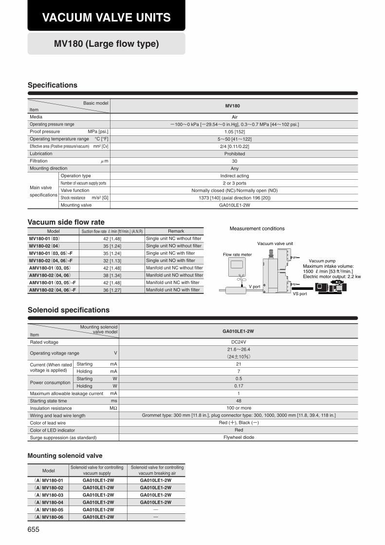
655
Air
-100~0 kPa [-29.54~0 in.Hg], 0.3~0.7 MPa [44~102 psi.]
1.05 [152]
5~50 [41~122]
2/4 [0.11/0.22]
Prohibited
30
Any
Indirect acting
2 or 3 ports
Normally closed (NC)/Normally open (NO)
1373 [140] (axial direction 196 [20])
GA010LE1-2W
MV180Item
Basic model
Specifications
Solenoid specifications
Mounting solenoid valve
Media
Operating pressure range
Proof pressure
Operating temperature range
Effective area (Positive pressure/vacuum)
Lubrication
Filtration
Mounting direction
Main valve
specifications
Operation type
Number of vacuum supply ports
Valve function
Shock resistance
Mounting valve
MPa [psi.]
°C [°F]
mm2 [Cv]
μm
m/s2 [G]
Item
Rated voltage
Operating voltage range
Current (When rated voltage is applied)
Power consumption
Maximum allowable leakage current
Starting state time
Insulation resistance
Wiring and lead wire length
Color of lead wire
Color of LED indicator
Surge suppression (as standard)
DC24V
21.6~26.4
(24±10%)
21
7
1
48
V
mA
mA
W
W
mA
ms
MΩ 100 or more
Grommet type: 300 mm [11.8 in.], plug connector type: 300, 1000, 3000 mm [11.8, 39.4, 118 in.]
Red (+), Black (-)
Red
Flywheel diode
0.5
0.17
GA010LE1-2W
Model
(A)MV180-01
(A)MV180-02
(A)MV180-03
(A)MV180-04
(A)MV180-05
(A)MV180-06
GA010LE1-2W
GA010LE1-2W
GA010LE1-2W
GA010LE1-2W
―
―
GA010LE1-2W
GA010LE1-2W
GA010LE1-2W
GA010LE1-2W
GA010LE1-2W
GA010LE1-2W
Vacuum side flow rateModel
MV180-01(03)
MV180-02(04)
MV180-01(03, 05)-F
MV180-02(04, 06)-F
AMV180-01(03, 05)
AMV180-02(04, 06)
AMV180-01(03, 05)-F
AMV180-02(04, 06)-F
Remark
Single unit NC without filter
Single unit NO without filter
Single unit NC with filter
Single unit NO with filter
Manifold unit NC without filter
Manifold unit NO without filter
Manifold unit NC with filter
Manifold unit NO with filter
Suction flow rate R/min [ft.3/min.] (A.N.R)
42 [1.48]
35 [1.24]
35 [1.24]
32 [1.13]
42 [1.48]
38 [1.34]
42 [1.48]
36 [1.27]
Starting
Holding
Starting
Holding
Flow rate meter
Vacuum pump
Vacuum valve unit
V port
VS port
Maximum intake volume: 1500 R/min [53 ft.3/min.]Electric motor output: 2.2 kw
Measurement conditions
MV180 (Large flow type)
VACUUM VALVE UNITS
Mounting solenoidvalve model
Solenoid valve for controllingvacuum supply
Solenoid valve for controllingvacuum breaking air
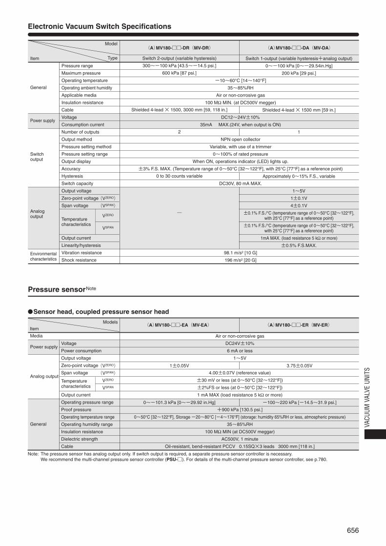
656
VACU
UM V
ALVE
UNI
TS
Electronic Vacuum Switch Specifications
Model
Item
Pressure range
Maximum pressure
Operating temperature
Operating ambient humidity
Applicable media
Insulation resistance
Cable
Voltage
Consumption current
Number of outputs
Output method
Pressure setting method
Pressure setting range
Output display
Accuracy
Hysteresis
Switch capacity
Output voltage
Zero-point voltage
Span voltage
Temperature characteristics
Output current
Linearity/hysteresis
Vibration resistance
Shock resistance
General
Power supply
Switch output
Analog output
Environmental characteristics
Switch 2-output (variable hysteresis)
300~-100 kPa [43.5~-14.5 psi.]
600 kPa [87 psi.]
Shielded 4-lead × 1500, 3000 mm [59, 118 in.]
2
0 to 30 counts variable
―
Switch 1-output (variable hysteresis+analog output)
0~-100 kPa [0~-29.54in.Hg]
200 kPa [29 psi.]
Shielded 4-lead × 1500 mm [59 in.]
1
Approximately 0~15% F.S., variable
1~5V
1±0.1V
4±0.1V
±0.1% F.S./°C (temperature range of 0~50°C [32~122°F], with 25°C [77°F] as a reference point)
±0.1% F.S./°C (temperature range of 0~50°C [32~122°F], with 25°C [77°F] as a reference point)
1mA MAX. (load resistance 5 kΩ or more)
±0.5% F.S.MAX.
-10~60°C [14~140°F]
35~85%RH
Air or non-corrosive gas
100 MΩ MIN. (at DC500V megger)
DC12~24V±10%
35mA MAX.(24V, when output is ON)
NPN open collector
Variable, with use of a trimmer
0~100% of rated pressure
When ON, operations indicator (LED) lights up.
±3% F.S. MAX. (Temperature range of 0~50°C [32~122°F], with 25°C [77°F] as a reference point)
DC30V, 80 mA MAX.
98.1 m/s2 [10 G]
196 m/s2 [20 G]
(A)MV180-□□-DR(MV-DR) (A)MV180-□□-DA(MV-DA)
(VZERO)
(VSPAN)
VZERO
VSPAN
(VZERO)
(VSPAN)
VZERO
VSPAN
Air or non-corrosive gas
DC24V±10%
6 mA or less
1~5V
4.00±0.07V (reference value)
±30 mV or less (at 0~50°C [32~122°F])
±2%FS or less (at 0~50°C [32~122°F])
1 mA MAX (load resistance 5 kΩ or more)
+900 kPa [130.5 psi.]
0~50°C [32~122°F], Storage -20~80°C [-4~176°F] (storage: humidity 65%RH or less, atmospheric pressure)
35~85%RH
100 MΩ MIN (at DC500V meggar)
AC500V, 1 minute
Oil-resistant, bend-resistant PCCV 0.15SQ×3 leads 3000 mm [118 in.]
(A)MV180-□□-EA(MV-EA) (A)MV180-□□-ER(MV-ER)Item
Models
Pressure sensorNote
Media
Power supply
Analog output
General
Voltage
Power consumption
Output voltage
Zero-point voltage
Span voltage
Output current
Operating pressure range
Proof pressure
Operating temperature range
Operating humidity range
Insulation resistance
Dielectric strength
Cable
1±0.05V
0~-101.3 kPa [0~-29.92 in.Hg]
3.75±0.05V
-100~220 kPa [-14.5~31.9 psi.]
●Sensor head, coupled pressure sensor head
Note: The pressure sensor has analog output only. If switch output is required, a separate pressure sensor controller is necessary.We recommend the multi-channel pressure sensor controller (PSU-□). For details of the multi-channel pressure sensor controller, see p.780.
Type
Temperaturecharacteristics
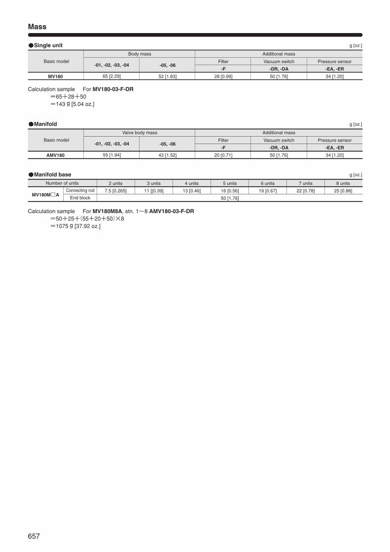
657
Mass
Basic model
Body mass
-01, -02, -03, -04
65 [2.29]
-05, -06
52 [1.83]
Additional mass
Filter
-F
28 [0.99]
Vacuum switch
-DR, -DA
50 [1.76]
Pressure sensor
-EA, -ER
34 [1.20]MV180
g [oz.]Single unit
Calculation sample For MV180-03-F-DR=65+28+50=143 g [5.04 oz.]
Basic model
Valve body mass
-01, -02, -03, -04
55 [1.94]
-05, -06
43 [1.52]
Additional mass
Filter
-F
20 [0.71]
Vacuum switch
-DR, -DA
50 [1.76]
Pressure sensor
-EA, -ER
34 [1.20]AMV180
MV180M□A
g [oz.]Manifold
Number of units 2 units
7.5 [0.265]Connecting rod
End block
3 units
11 [[0.39]
4 units
13 [0.46]
5 units
16 [0.56]
50 [1.76]
6 units
19 [0.67]
7 units
22 [0.78]
8 units
25 [0.88]
g [oz.]Manifold base
Calculation sample For MV180M8A, stn. 1~8 AMV180-03-F-DR=50+25+(55+20+50)×8=1075 g [37.92 oz.]
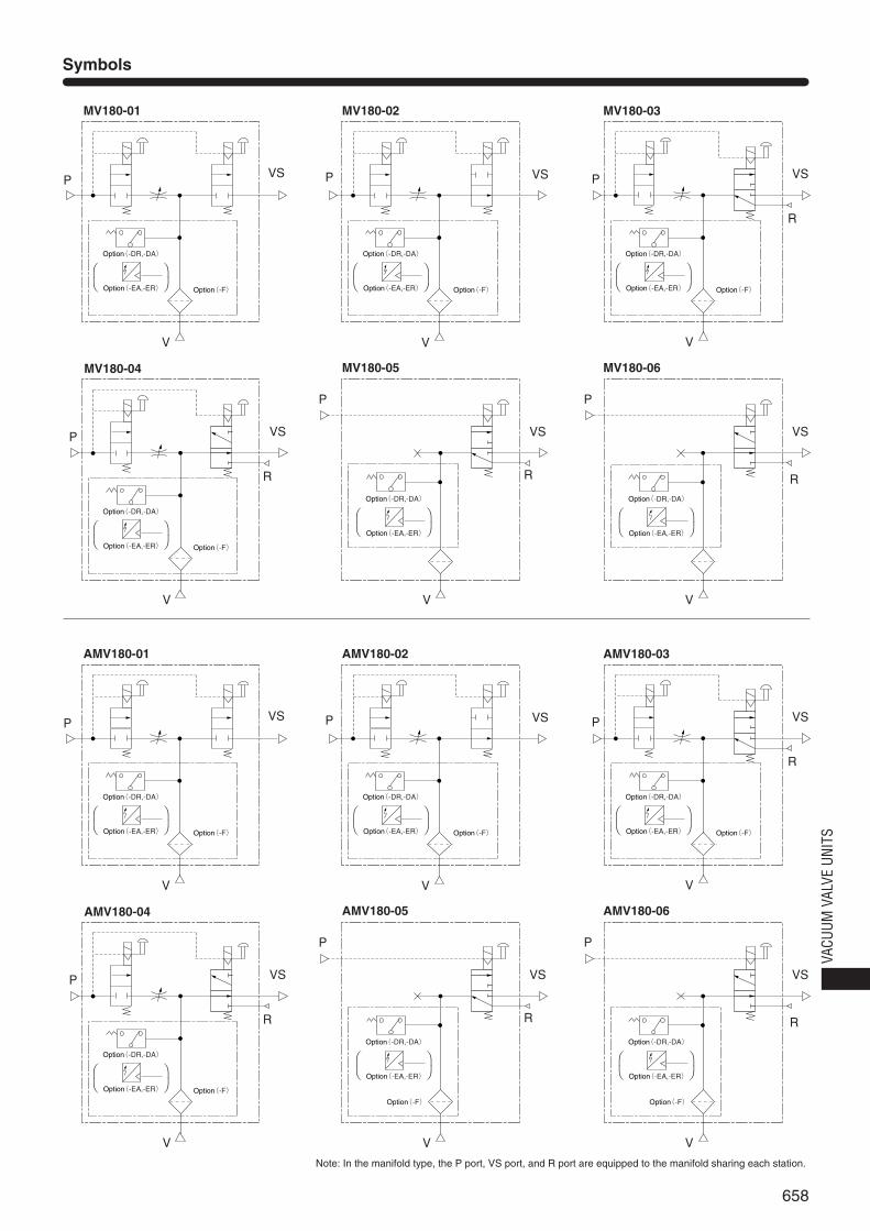
658
VACU
UM V
ALVE
UNI
TS
Symbols
AMV180-01 AMV180-02
P VSP
V
VS P VS
AMV180-03
R
P VS
AMV180-04
R
V V
V
VS
AMV180-05
R
VS
AMV180-06
R
V V
P P
MV180-01 MV180-02
P VSP
V
VS P VS
MV180-03
R
P VS
MV180-04
R
V V
V
VS
MV180-05
R
VS
MV180-06
R
V V
P P
Option(-DR,-DA)
Option(-F) Option(-EA,-ER)
⎛ ⎞⎝ ⎠
Option(-DR,-DA)
Option(-F) Option(-EA,-ER)
⎛ ⎞⎝ ⎠
Option(-DR,-DA)
Option(-F) Option(-EA,-ER)
⎛ ⎞⎝ ⎠
Option(-DR,-DA)
Option(-F) Option(-EA,-ER)
⎛ ⎞⎝ ⎠
Option(-DR,-DA)
Option(-EA,-ER)
⎛ ⎞⎝ ⎠
Option(-DR,-DA)
Option(-EA,-ER)
⎛ ⎞⎝ ⎠
Option(-DR,-DA)
Option(-F) Option(-EA,-ER)
⎛ ⎞⎝ ⎠
Option(-DR,-DA)
Option(-F) Option(-EA,-ER)
⎛ ⎞⎝ ⎠
Option(-DR,-DA)
Option(-F) Option(-EA,-ER)
⎛ ⎞⎝ ⎠
Option(-DR,-DA)
Option(-F) Option(-EA,-ER)
⎛ ⎞⎝ ⎠
Option(-DR,-DA)
Option(-EA,-ER)
⎛ ⎞⎝ ⎠
Option(-F)
Option(-DR,-DA)
Option(-EA,-ER)
⎛ ⎞⎝ ⎠
Option(-F)
Note: In the manifold type, the P port, VS port, and R port are equipped to the manifold sharing each station.
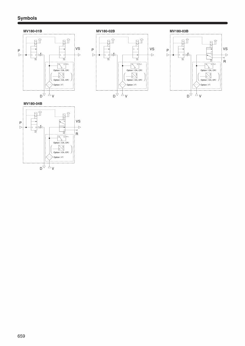
659
Symbols
MV180-01B MV180-02B
P VSP
VD D
VS P VS
MV180-03B
R
P VS
MV180-04B
R
V V
V
Option(-DA,-DR)
Option(-F)
Option(-EA,-ER)
⎛ ⎞⎝ ⎠
Option(-DA,-DR)
Option(-F)
Option(-EA,-ER)
⎛ ⎞⎝ ⎠
D
Option(-DA,-DR)
Option(-F)
Option(-EA,-ER)
⎛ ⎞⎝ ⎠
Option(-DA,-DR)
Option(-F)
Option(-EA,-ER)
⎛ ⎞⎝ ⎠
D
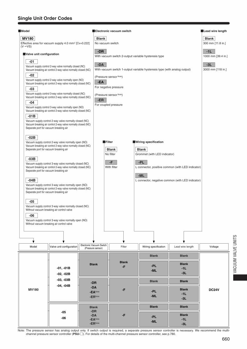
660
VACU
UM V
ALVE
UNI
TS
Single Unit Order Codes
Note: The pressure sensor has analog output only. If switch output is required, a separate pressure sensor controller is necessary. We recommend the multi-channel pressure sensor controller (PSU-□). For details of the multi-channel pressure sensor controller, see p.780.
Blank
-PL-ML
FilterElectronic Vacuum Switch(Pressure sensor)
Blank
Blank
-1L-3L
Lead wire length VoltageModel Valve unit configuration Wiring specification
■Model
■Valve unit configuration
MV180Effective area for vacuum supply 4.0 mm2 [Cv=0.222](V→VS)
■Filter
■Lead wire length
■Wiring specification
■Electronic vacuum switch
-DRWith vacuum switch 2-output variable hysteresis type
-DAWith vacuum switch 1-output variable hysteresis type (with analog output)
Blank
-PL-ML
Blank
Blank
-1L-3L
Blank
-PL-ML
Blank
Blank
-1L-3L
Blank
-DR-DA
-EANote
-ERNote
Blank-DR-DA
-EANote
-ERNote
MV180
-01, -01B
-02, -02B
-03, -03B
-04, -04B
-05
-06
DC24V
Blank
-F
-F
-F
-EA
(Pressure sensor Note)
(Pressure sensor Note)
For negative pressure
-ERFor coupled pressure
-01Vacuum supply control 2-way valve normally closed (NC)Vacuum breaking air control 2-way valve normally closed (NC)
-02Vacuum supply control 2-way valve normally open (NO)Vacuum breaking air control 2-way valve normally closed (NC)
-03Vacuum supply control 3-way valve normally closed (NC)Vacuum breaking air control 2-way valve normally closed (NC)
-04Vacuum supply control 3-way valve normally open (NO)Vacuum breaking air control 2-way valve normally closed (NC)
-01BVacuum supply control 2-way valve normally closed (NC)Vacuum breaking air control 2-way valve normally closed (NC)Separate port for vacuum breaking air
-02BVacuum supply control 2-way valve normally open (NO)Vacuum breaking air control 2-way valve normally closed (NC)Separate port for vacuum breaking air
-03BVacuum supply control 3-way valve normally closed (NC)Vacuum breaking air control 2-way valve normally closed (NC)Separate port for vacuum breaking air
-04BVacuum supply control 3-way valve normally open (NO)Vacuum breaking air control 2-way valve normally closed (NC)Separate port for vacuum breaking air
-05Vacuum supply control 3-way valve normally closed (NC)Without vacuum breaking air control valve
-06Vacuum supply control 3-way valve normally open (NO)Without vacuum breaking air control valve
BlankNo vacuum switch
BlankNo filter
-FWith filter
BlankGrommet (with LED indicator)
-PLL connector, positive common (with LED indicator)
-MLL connector, negative common (with LED indicator)
Blank300 mm [11.8 in.]
-1L1000 mm [39.4 in.]
-3L3000 mm [118 in.]

661
Manifold Order Codes
Notes: 1. Mounting location from the left so that places the vacuum breaking flow adjustment needle on top, and the vacuum port (V) side in front.2. The pressure sensor has analog output only. If switch output is required, a separate pressure sensor controller is necessary. We recommend the multi-
channel pressure sensor controller (PSU-□). For details of the multi-channel pressure sensor controller, see p.780.
Blank
-PL-ML
ModelManifoldmodel
Solenoidvalve type Station
Blank
Blank -1L-3L
Filter VoltageManifoldbasic model
Number ofunits
Valve unitconfiguration
Vacuum switch(Pressure sensor )
Wiringspecification
Lead wirelength
■Manifold basic model
■Valve unit configuration
MV180MFor mounting AMV180
■Model
AMV180Effective area for vacuumsupply side 4.0 mm2
[Cv: 0.222] (V→VS)
■Manifold model
AA type manifold
■Filter
■Lead wire length
■Wiring specification
■Electronic vacuum switch
-DRWith vacuum switch 2-output variable hysteresis type
-DAWith vacuum switch 1-output variable hysteresis type (with analog output)
Blank
-PL-ML
Blank
Blank -1L-3L
Blank
-PL-ML
Blank
Blank -1L-3L
Blank
-PL-ML
Blank
Blank -1L-3L
Blank
-11
Blank
-11
-01-03-05
-02-04-06
-01-03-05
-02-04-06
Blank
Blank
-DR-DA-EANote2
-ERNote2
MV180M AMV180
stn.□・・・
stn.□Note1
2・・・8
A DC24V
Blank
-F
Manifold model Mounting valve model
■Solenoid valve type forcontrolling vacuum supply
Blank
For mounting normally closed (NC) type
-11For mounting normally open (NO) type
BlankNo vacuum switch
-EA
(Pressure sensorNote 2)
(Pressure sensorNote 2)
For negative pressure
-ERFor coupled pressure
Vacuum supply control 2-way valvenormally closed (NC)
Vacuum breaking air control 2-way valvenormally closed (NC)
Vacuum supply control 2-way valvenormally open (NO)
Vacuum breaking air control 2-way valvenormally closed (NC)
Vacuum supply control 3-way valvenormally closed (NC)
Vacuum breaking air control 2-way valvenormally closed (NC)
Vacuum supply control 3-way valvenormally open (NO)
Vacuum breaking air control 2-way valvenormally closed (NC)
Vacuum supply control 3-way valvenormally closed (NC)
Without vacuum breaking air control valve
Vacuum supply control 3-way valvenormally open (NO)
Without vacuum breaking air control valve
-02
-01
-03
-04
-05
-06
BlankNo filter
-FWith filter
BlankGrommet(With LED indicator)
-PLL connector, positive common(With LED indicator)
-MLL connector, negative common(With LED indicator)
Blank300 mm [11.8 in.]
-1L1000 mm [39.4 in.]
-3L3000 mm [118 in.]
Aty
pem
anifo
ld
Solenoid valvefor controllingvacuum supply,normallyclosed type
Solenoid valvefor controllingvacuum supply,normally opentype
Solenoid valvefor controllingvacuum supply,normally closedtype
Solenoid valvefor controllingvacuum supply,normally opentype
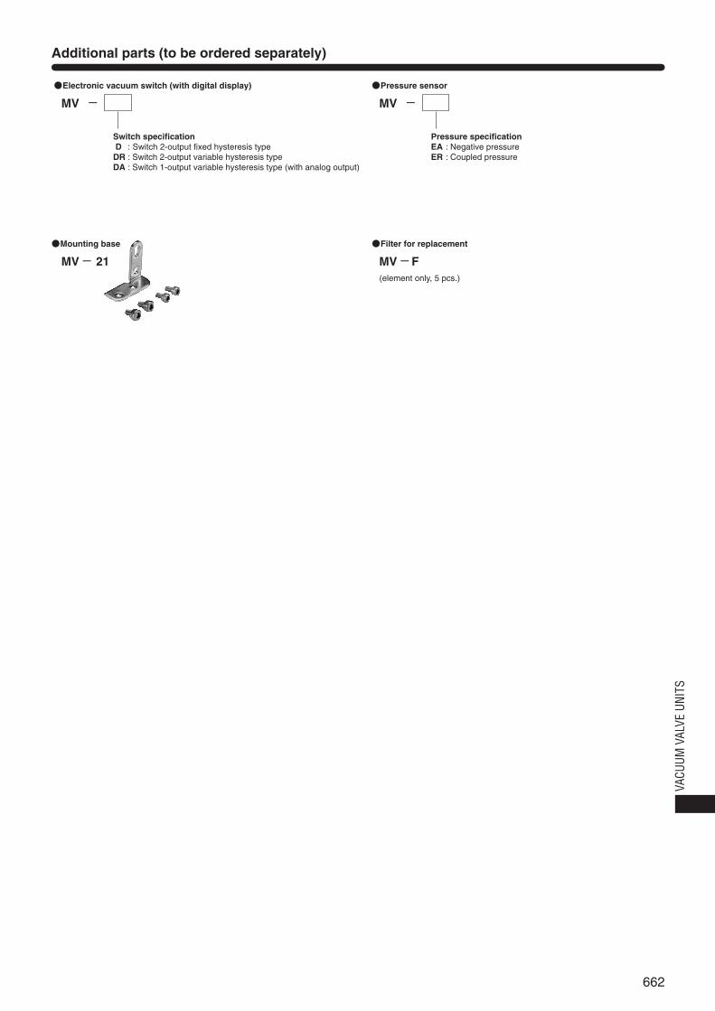
662
VACU
UM V
ALVE
UNI
TS
Additional parts (to be ordered separately)
MV
Switch specificationD : Switch 2-output fixed hysteresis typeDR : Switch 2-output variable hysteresis typeDA : Switch 1-output variable hysteresis type (with analog output)
●Electronic vacuum switch (with digital display)
- MV
Pressure specificationEA : Negative pressureER : Coupled pressure
●Pressure sensor
-
MV F(element only, 5 pcs.)
●Filter for replacement
-MV 21
●Mounting base
-
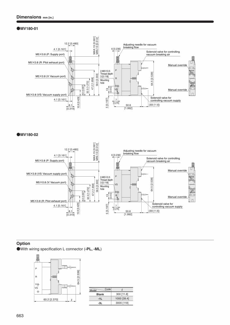
663
Dimensions mm [in.]
P
R
V
VS
64.5
[2.5
39]
12.2 [0.480]
●MV180-01
●MV180-02
P
6 [0.236]64
.5 [2
.539
]
5 [0
.197
]13
[0.5
12]
4.1 [0.161]
58.5
[2.3
03]
20.5
[0.8
07]
32.3
[1.2
72]
47.2
[1.8
58]
MIN
.13
[0.5
12]
MA
X.1
5 [0
.591
]
8.1[0.319]
4.1 [0.161]
R
V
VS
50.6[1.992]
(300 [11.8])
12.2 [0.480]
Option●With wiring specification L connector (-PL, -ML)
VS
V
R
P
64.5
[2.5
39]
60.2 [2.370] R
10.9
[0.4
29]M5×0.8 (R: Pilot exhaust port)
M5×0.8 (V: Vacuum port)
M5×0.8 (VS: Vacuum supply port)
M5×0.8 (P: Supply port)
Adjusting needle for vacuumbreaking flow
Solenoid valve for controlling vacuum breaking air
7[0.276]
Solenoid valve for controlling vacuum supply
Manual override
Manual override
4.1 [0.161]
M5×0.8 (R: Pilot exhaust port)
M5×0.8 (V: Vacuum port)
M5×0.8 (VS: Vacuum supply port)
M5×0.8 (P: Supply port)
8.1[0.319]
4.1 [0.161]58
.5 [2
.303
]
20.5
[0.8
07]
32.3
[1.2
72]
47.2
[1.8
58]
10.9
[0.4
29]
5 [0
.197
]13
[0.5
12]
MIN
.13
[0.5
12]
MA
X.1
5 [0
.591
]
6 [0.236]
Adjusting needle for vacuumbreaking flow
7[0.276]
50.6[1.992]
(300 [11.8])
Solenoid valve for controlling vacuum supply
Solenoid valve for controlling vacuum breaking air
Manual override
Manual override
2-M3×0.5Thread depth 3 [0.118] Mountinghole
2-M3×0.5Thread depth 3 [0.118] Mountinghole
Model
Blank
-1L
-3L
Code R
300 [11.8]
1000 [39.4]
3000 [118]
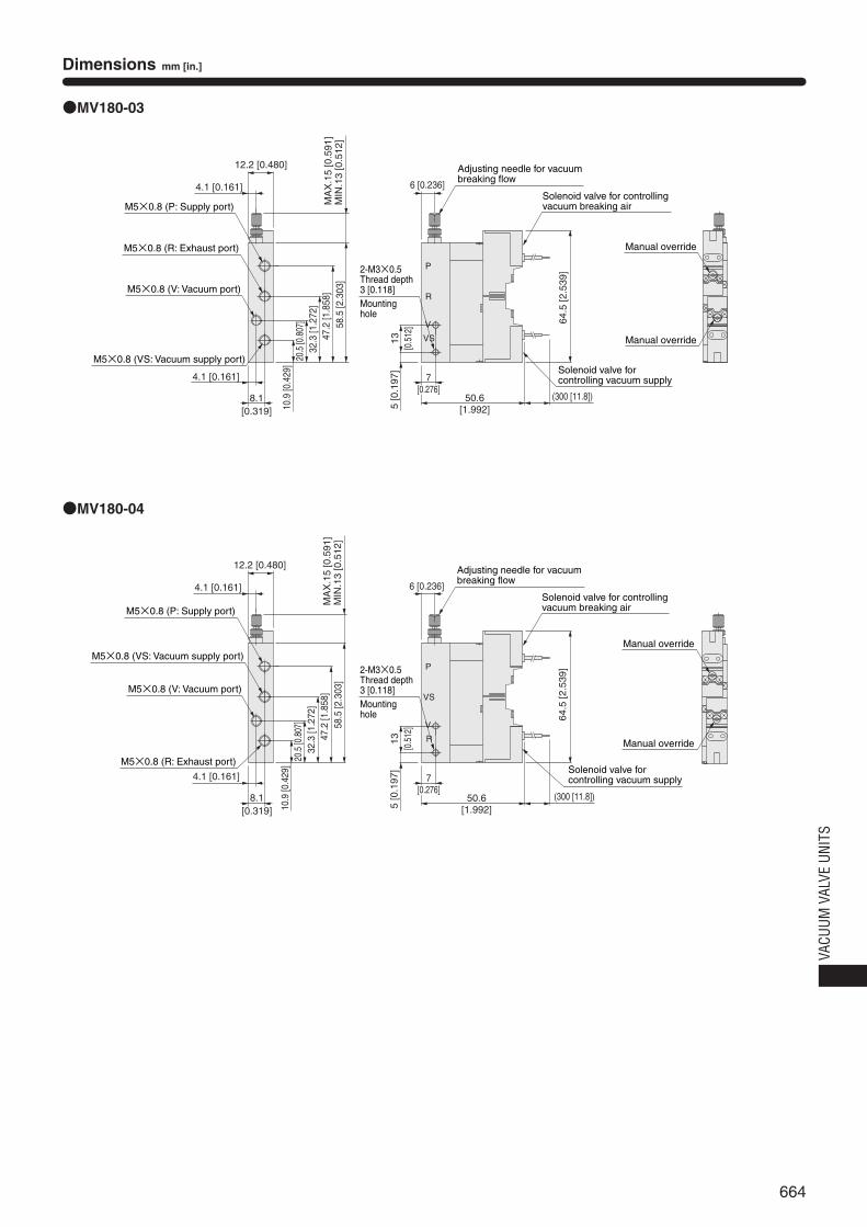
664
VACU
UM V
ALVE
UNI
TS
Dimensions mm [in.]
●MV180-03
●MV180-04
P
R
V
VS
64.5
[2.5
39]
P
R
V
VSM5×0.8 (V: Vacuum port)
M5×0.8 (R: Exhaust port)
M5×0.8 (VS: Vacuum supply port)
M5×0.8 (P: Supply port)
8.1[0.319]
4.1 [0.161]
4.1 [0.161]
12.2 [0.480]
MIN
.13
[0.5
12]
MA
X.1
5 [0
.591
]58
.5 [2
.303
]
20.5
[0.8
07]
32.3
[1.2
72]
47.2
[1.8
58]
10.9
[0.4
29]
5 [0
.197
]13
[0.5
12]
7[0.276]
7[0.276]
50.6[1.992]
(300 [11.8])
64.5
[2.5
39]
Solenoid valve for controlling vacuum supply
6 [0.236]
Adjusting needle for vacuumbreaking flow
Solenoid valve for controlling vacuum breaking air
Manual override
Manual override
Manual override
Manual override
6 [0.236]
Adjusting needle for vacuumbreaking flow
Solenoid valve for controlling vacuum breaking air
50.6[1.992]
(300 [11.8])
Solenoid valve for controlling vacuum supply
5 [0
.197
]13
[0.5
12]
4.1 [0.161]
12.2 [0.480]
MIN
.13
[0.5
12]
MA
X.1
5 [0
.591
]
M5×0.8 (V: Vacuum port)
M5×0.8 (R: Exhaust port)
M5×0.8 (VS: Vacuum supply port)
M5×0.8 (P: Supply port)
8.1[0.319]
4.1 [0.161]
58.5
[2.3
03]
20.5
[0.8
07]
32.3
[1.2
72]
47.2
[1.8
58]
10.9
[0.4
29]
2-M3×0.5Thread depth 3 [0.118] Mountinghole
2-M3×0.5Thread depth 3 [0.118] Mountinghole
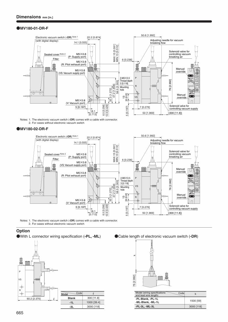
665
Dimensions mm [in.]
●MV180-01-DR-F
●MV180-02-DR-F
Option●With L connector wiring specification (-PL, -ML) ●Cable length of electronic vacuum switch (-DR)
5 [0
.197
]13
[0.5
12]
22.2 [0.874]
14.1 [0.555]
6.5
[0.2
56]
10.9
[0.4
29]
47.2
[1.8
58]
58.5
[2.3
03]
MIN
.13
[0.5
12]
MA
X.1
5 [0
.591
]
32.3
[1.2
72]
5 [0.197]
18.1[0.713]
7 [0.276]
50 [1.969]
VS
R
P
V
50.6 [1.992]
6 [0.236]
P1
MV-DR
P2
kPa
KOGANEI
R
VS
P
VP1
MV-DR
P2
kPa
KOGANEI
60.2 [2.370]
R
P
VS
R
k76
[2.9
92]
Filter
Sealed cover Note 2
Electronic vacuum switch (-DR) Note 1
(with digital display)
Filter
Sealed cover Note 2
Electronic vacuum switch (-DR) Note 1
(with digital display)
M5×0.8(R: Pilot exhaust port)
M5×0.8(VS: Vacuum supply port)
M5×0.8(P: Supply port)
M5×0.8(VS: Vacuum supply port)
M5×0.8(R: Pilot exhaust port)
M5×0.8(P: Supply port)
M5×0.8(V: Vacuum port)
M5×0.8(V: Vacuum port)
5 [0.197]
18.1[0.713] 6.
5 [0
.256
]10
.9 [0
.429
]
47.2
[1.8
58]
58.5
[2.3
03]
32.3
[1.2
72]
22.2 [0.874]
14.1 [0.555]
MIN
.13
[0.5
12]
MA
X.1
5 [0
.591
]
2-M3×0.5Thread depth 3 [0.118] Mountinghole
2-M3×0.5Thread depth 3 [0.118] Mountinghole
Adjusting needle for vacuum breaking flow
Solenoid valve for controlling vacuum breaking air
50.6 [1.992]
6 [0.236]
Adjusting needle for vacuum breaking flow
Solenoid valve for controlling vacuum breaking air
76 [2
.992
]
Manualoverride
Manualoverride
76 [2
.992
]Manualoverride
Manualoverride
(300 [11.8])
Solenoid valve for controlling vacuum supply
5 [0
.197
]13
[0.5
12]
7 [0.276]
50 [1.969] (300 [11.8])
Solenoid valve for controlling vacuum supply
Notes: 1. The electronic vacuum switch (-DR) comes with a cable with connector.2. For cases without electronic vacuum switch
Notes: 1. The electronic vacuum switch (-DR) comes with a cable with connector.2. For cases without electronic vacuum switch
Model
Blank
-1L
-3L
Code R
300 [11.8]
1000 [39.4]
3000 [118]
Model (wiring specifications and lead wire length)
-PL-Blank, -PL-1L-ML-Blank, -ML-1L
-PL-3L, -ML-3L
Code k
1500 [59]
3000 [118]
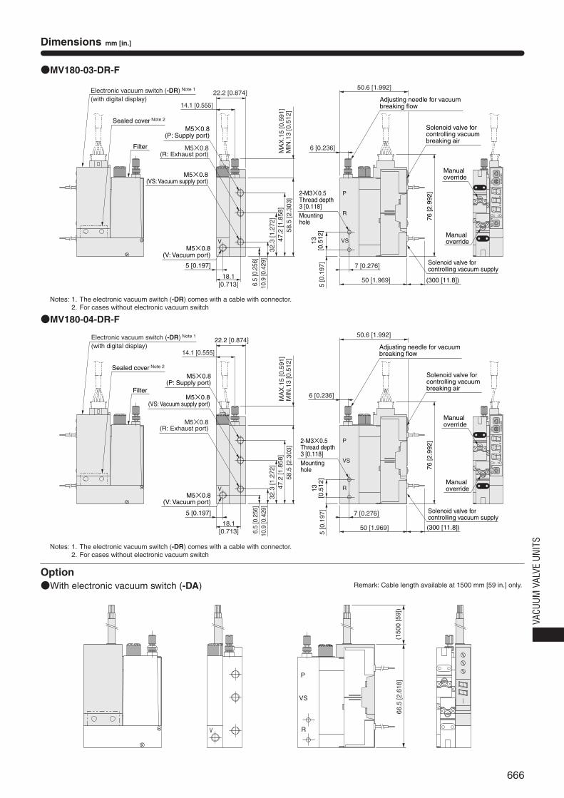
666
VACU
UM V
ALVE
UNI
TS
Dimensions mm [in.]
●MV180-03-DR-F
●MV180-04-DR-F
Option●With electronic vacuum switch (-DA)
M5×0.8(R: Exhaust port)
VS
R
P
V
P1
MV-DR
P2
kPa
KOGANEI
R
VS
P
VP1
MV-DR
P2
kPa
KOGANEI
V R
P
VS
(150
0 [5
9])
66.5
[2.6
18]
Filter
Sealed cover Note 2
Electronic vacuum switch (-DR) Note 1
(with digital display)22.2 [0.874]
14.1 [0.555]
M5×0.8(VS: Vacuum supply port)
M5×0.8(P: Supply port)
5 [0.197]
18.1[0.713]
M5×0.8(V: Vacuum port)
MIN
.13
[0.5
12]
MA
X.1
5 [0
.591
]
6.5
[0.2
56]
10.9
[0.4
29]
47.2
[1.8
58]
58.5
[2.3
03]
32.3
[1.2
72]
6.5
[0.2
56]
10.9
[0.4
29]
47.2
[1.8
58]
58.5
[2.3
03]
32.3
[1.2
72]
MIN
.13
[0.5
12]
MA
X.1
5 [0
.591
]
Filter
Sealed cover Note 2
Electronic vacuum switch (-DR) Note 1
(with digital display)
M5×0.8(R: Exhaust port)
22.2 [0.874]
14.1 [0.555]
M5×0.8(VS: Vacuum supply port)
M5×0.8(P: Supply port)
5 [0.197]
18.1[0.713]
M5×0.8(V: Vacuum port)
50.6 [1.992]
6 [0.236]
Adjusting needle for vacuum breaking flow
5 [0
.197
]13
[0.5
12]
2-M3×0.5Thread depth 3 [0.118] Mountinghole
5 [0
.197
]13
[0.5
12]
2-M3×0.5Thread depth 3 [0.118] Mountinghole
Solenoid valve for controlling vacuum breaking air
76 [2
.992
]
Manualoverride
Manualoverride
7 [0.276]
50 [1.969] (300 [11.8])
Solenoid valve for controlling vacuum supply
50.6 [1.992]
6 [0.236]
Adjusting needle for vacuum breaking flow
Solenoid valve for controlling vacuum breaking air
76 [2
.992
]
Manualoverride
Manualoverride
7 [0.276]
50 [1.969]
Solenoid valve for controlling vacuum supply
(300 [11.8])
Remark: Cable length available at 1500 mm [59 in.] only.
Notes: 1. The electronic vacuum switch (-DR) comes with a cable with connector.2. For cases without electronic vacuum switch
Notes: 1. The electronic vacuum switch (-DR) comes with a cable with connector.2. For cases without electronic vacuum switch
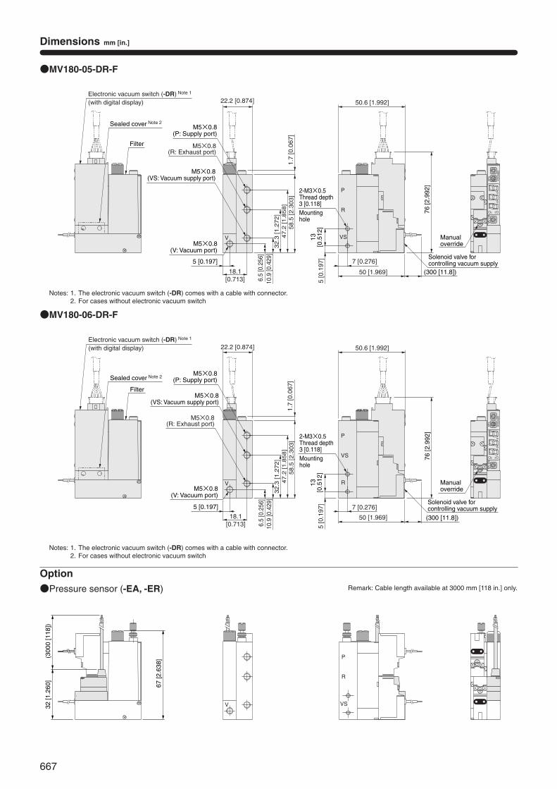
667
Dimensions mm [in.]
●MV180-05-DR-F
●MV180-06-DR-F
1.7
[0.0
67]
VS
R
P
V
KOGANEI
kPa
P2
MV-DRP1
R
VS
P
V
KOGANEI
kPa
P2
MV-DRP1
Option●Pressure sensor (-EA, -ER)
VS
R
P
V32 [1
.260
](3
000
[118
])
67 [2
.638
]
Filter
Sealed cover Note 2
Electronic vacuum switch (-DR) Note 1
(with digital display)
M5×0.8(R: Exhaust port)
22.2 [0.874]
M5×0.8(VS: Vacuum supply port)
M5×0.8(P: Supply port)
5 [0.197]
18.1[0.713]
M5×0.8(V: Vacuum port)
6.5
[0.2
56]
10.9
[0.4
29]
47.2
[1.8
58]
58.5
[2.3
03]
32.3
[1.2
72]
Filter
Sealed cover Note 2
Electronic vacuum switch (-DR) Note 1
(with digital display)
M5×0.8(R: Exhaust port)
22.2 [0.874]
M5×0.8(VS: Vacuum supply port)
M5×0.8(P: Supply port)
5 [0.197]
18.1[0.713]
M5×0.8(V: Vacuum port)
6.5
[0.2
56]
10.9
[0.4
29]
47.2
[1.8
58]
58.5
[2.3
03]
32.3
[1.2
72]
1.7
[0.0
67]
50.6 [1.992]
2-M3×0.5Thread depth 3 [0.118] Mountinghole
50.6 [1.992]
2-M3×0.5Thread depth 3 [0.118] Mountinghole
5 [0
.197
]13
[0.5
12]
5 [0
.197
]13
[0.5
12]
7 [0.276]
50 [1.969]
7 [0.276]
50 [1.969]
76 [2
.992
]
(300 [11.8])
Solenoid valve for controlling vacuum supply
76 [2
.992
]
(300 [11.8])
Solenoid valve for controlling vacuum supply
Manualoverride
Manualoverride
Remark: Cable length available at 3000 mm [118 in.] only.
Notes: 1. The electronic vacuum switch (-DR) comes with a cable with connector.2. For cases without electronic vacuum switch
Notes: 1. The electronic vacuum switch (-DR) comes with a cable with connector.2. For cases without electronic vacuum switch
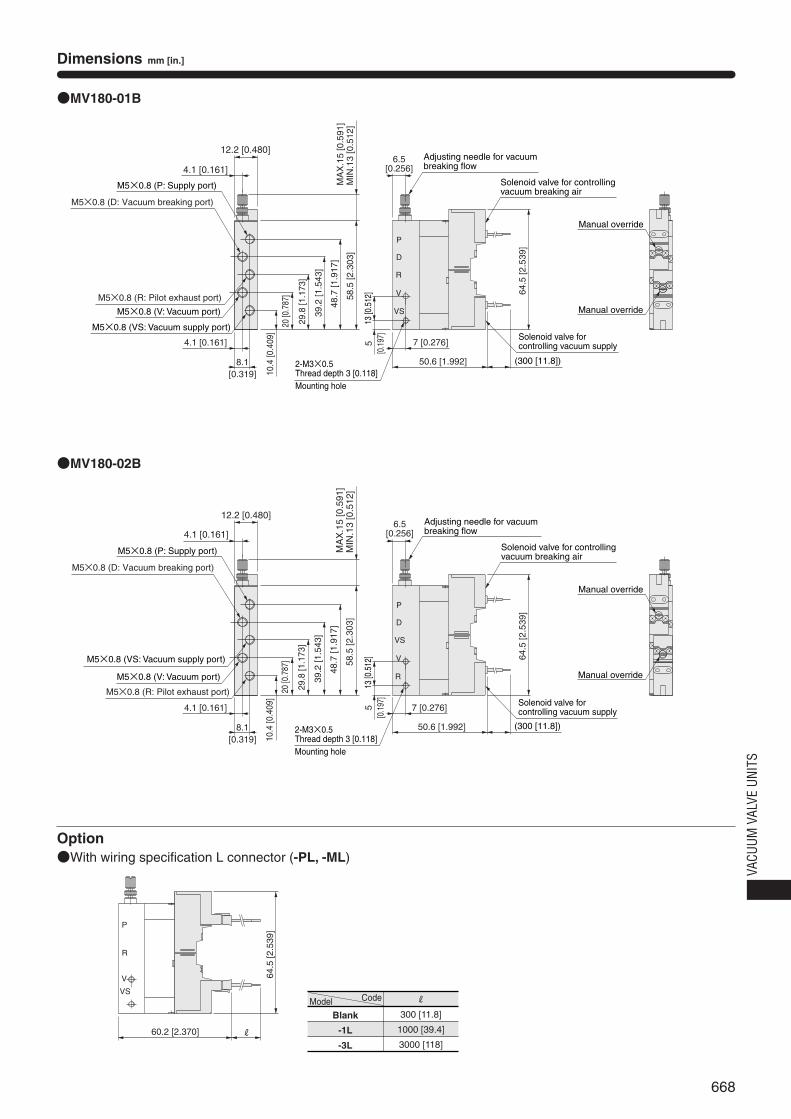
668
VACU
UM V
ALVE
UNI
TS
Dimensions mm [in.]
●MV180-01B
●MV180-02B
Option●With wiring specification L connector (-PL, -ML)
VS
V
R
P
64.5
[2.5
39]
60.2 [2.370] R
P
R
V
VS
7 [0.276]
6.5[0.256]
64.5
[2.5
39]
13 [0
.512
]
4.1 [0.161]
58.5
[2.3
03]
8.1[0.319]
4.1 [0.161]
M5×0.8 (D: Vacuum breaking port)
50.6 [1.992]
12.2 [0.480]
D
M5×0.8 (R: Pilot exhaust port)
10.4
[0.4
09]
20 [0
.787
]
48.7
[1.9
17]
29.8
[1.1
73]
39.2
[1.5
43]
P
VS
V
R
64.5
[2.5
39]
MIN
.13
[0.5
12]
MA
X.1
5 [0
.591
]
D
M5×0.8 (VS: Vacuum supply port)
M5×0.8 (P: Supply port)
M5×0.8 (V: Vacuum port)
MIN
.13
[0.5
12]
MA
X.1
5 [0
.591
]
2-M3×0.5Thread depth 3 [0.118] Mounting hole
5[0
.197
]
(300 [11.8])
Solenoid valve for controlling vacuum supply
Adjusting needle for vacuum breaking flow
Solenoid valve for controlling vacuum breaking air
Manual override
Manual override
4.1 [0.161]
M5×0.8 (D: Vacuum breaking port)
12.2 [0.480]
M5×0.8 (P: Supply port)
M5×0.8 (R: Pilot exhaust port)
M5×0.8 (VS: Vacuum supply port)
M5×0.8 (V: Vacuum port)
8.1[0.319]
4.1 [0.161]
2-M3×0.5Thread depth 3 [0.118] Mounting hole
58.5
[2.3
03]
10.4
[0.4
09]
20 [0
.787
]
48.7
[1.9
17]
29.8
[1.1
73]
39.2
[1.5
43]
13 [0
.512
]5
[0.1
97]
7 [0.276]
50.6 [1.992] (300 [11.8])
Solenoid valve for controlling vacuum supply
6.5[0.256]
Adjusting needle for vacuum breaking flow
Solenoid valve for controlling vacuum breaking air
Manual override
Manual override
Model
Blank
-1L
-3L
Code R
300 [11.8]
1000 [39.4]
3000 [118]
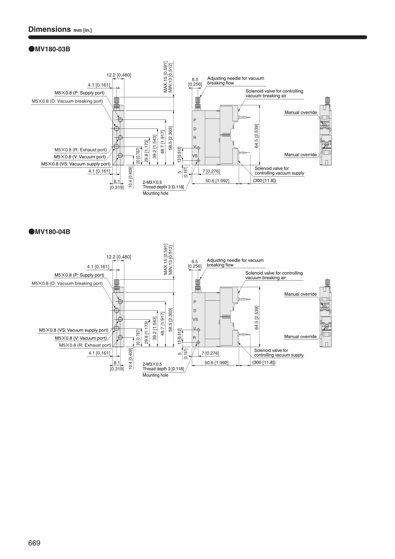
669
Dimensions mm [in.]
●MV180-03B
●MV180-04B
P
R
V
VS
D
P
VS
V
R
D
4.1 [0.161]
M5×0.8 (D: Vacuum breaking port)
12.2 [0.480]
M5×0.8 (P: Supply port)
M5×0.8 (R: Exhaust port)
M5×0.8 (VS: Vacuum supply port)
M5×0.8 (V: Vacuum port)
8.1[0.319]
4.1 [0.161]
4.1 [0.161]
M5×0.8 (D: Vacuum breaking port)
12.2 [0.480]
M5×0.8 (P: Supply port)
M5×0.8 (R: Exhaust port)
M5×0.8 (VS: Vacuum supply port)
M5×0.8 (V: Vacuum port)
8.1[0.319]
4.1 [0.161]
MIN
.13
[0.5
12]
MA
X.1
5 [0
.591
]M
IN.1
3 [0
.512
]M
AX
.15
[0.5
91]
2-M3×0.5Thread depth 3 [0.118] Mounting hole
2-M3×0.5Thread depth 3 [0.118] Mounting hole
58.5
[2.3
03]
10.4
[0.4
09]
20 [0
.787
]
48.7
[1.9
17]
29.8
[1.1
73]
39.2
[1.5
43]
58.5
[2.3
03]
10.4
[0.4
09]
20 [0
.787
]
48.7
[1.9
17]
29.8
[1.1
73]
39.2
[1.5
43]
6.5[0.256]
Adjusting needle for vacuum breaking flow
Solenoid valve for controlling vacuum breaking air
6.5[0.256]
Adjusting needle for vacuum breaking flow
Solenoid valve for controlling vacuum breaking air
64.5
[2.5
39]
13 [0
.512
]5
[0.1
97]
64.5
[2.5
39]
13 [0
.512
]5
[0.1
97]
7 [0.276]
50.6 [1.992] (300 [11.8])
Solenoid valve for controlling vacuum supply
7 [0.276]
50.6 [1.992] (300 [11.8])
Solenoid valve for controlling vacuum supply
Manual override
Manual override
Manual override
Manual override
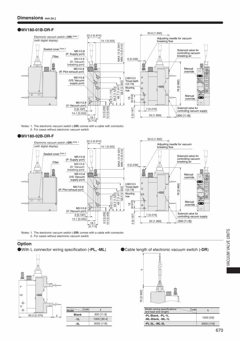
670
VACU
UM V
ALVE
UNI
TS
Dimensions mm [in.]
●MV180-01B-DR-F
●MV180-02B-DR-F
Option●With L connector wiring specification (-PL, -ML) ●Cable length of electronic vacuum switch (-DR)
60.2 [2.370]
R
P
VS
R
k76
[2.9
92]
M5×0.8(P: Supply port)
M5×0.8(D: Vacuum
breaking port)
VS
R
P
V
P1
MV-DR
P2
kPa
KOGANEI
D
14.1 [0.555]
48.7
[1.9
17]
29.8
[1.1
73]
39.2
[1.5
43]
R
VS
P
VP1
MV-DR
P2
kPa
KOGANEI
D
Filter
Sealed cover Note 2
Electronic vacuum switch (-DR) Note 1
(with digital display)
MIN
.13
[0.5
12]
MA
X.1
5 [0
.591
]M
IN.1
3 [0
.512
]M
AX
.15
[0.5
91]
22.2 [0.874]
14.1 [0.555]
M5×0.8(R: Pilot exhaust port)
M5×0.8(VS: Vacuumsupply port)
M5×0.8(V: Vacuum port)
5 [0.197]
18.1[0.713]
6.5
[0.2
56]
10.4
[0.4
09]
58.5
[2.3
03]
Filter
Sealed cover Note 2
Electronic vacuum switch (-DR) Note 1
(with digital display)
22.2 [0.874]
14.1 [0.555]
M5×0.8(P: Supply port)
M5×0.8(D: Vacuum
breaking port)
M5×0.8(R: Pilot exhaust port)
M5×0.8(VS: Vacuumsupply port)
14.1 [0.555]
M5×0.8(V: Vacuum port)
5 [0.197]
18.1[0.713]
48.7
[1.9
17]
29.8
[1.1
73]
39.2
[1.5
43]
6.5
[0.2
56]
10.4
[0.4
09]
58.5
[2.3
03]
2-M3×0.5Thread depth 3 [0.118] Mountinghole
2-M3×0.5Thread depth 3 [0.118] Mountinghole
50.6 [1.992]
6 [0.236]
Adjusting needle for vacuum breaking flow
Solenoid valve for controlling vacuum breaking air
76 [2
.992
]
Manualoverride
Manualoverride
5 [0
.197
]13
[0.5
12]
7 [0.276]
50 [1.969] (300 [11.8])
Solenoid valve for controlling vacuum supply
5 [0
.197
]13
[0.5
12]
7 [0.276]
50 [1.969] (300 [11.8])
Solenoid valve for controlling vacuum supply
50.6 [1.992]
6 [0.236]
Adjusting needle for vacuum breaking flow
Solenoid valve for controlling vacuum breaking air
76 [2
.992
]Manualoverride
Manualoverride
Notes: 1. The electronic vacuum switch (-DR) comes with a cable with connector.2. For cases without electronic vacuum switch
Notes: 1. The electronic vacuum switch (-DR) comes with a cable with connector.2. For cases without electronic vacuum switch
Model
Blank
-1L
-3L
Code R
300 [11.8]
1000 [39.4]
3000 [118]
Model (wiring specifications and lead wire length)
-PL-Blank, -PL-1L-ML-Blank, -ML-1L
-PL-3L, -ML-3L
Code k
1500 [59]
3000 [118]
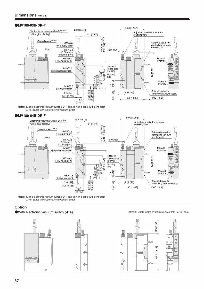
671
Dimensions mm [in.]
●MV180-03B-DR-F
●MV180-04B-DR-F
Option●With electronic vacuum switch (-DA)
V R
P
VS
(150
0 [5
9])
66.5
[2.6
18]
VS
R
P
V
P1
MV-DR
P2
kPa
KOGANEI
D
R
VS
P
VP1
MV-DR
P2
kPa
KOGANEI
D
Filter
Sealed cover Note 2
Electronic vacuum switch (-DR) Note 1
(with digital display)
Filter
Sealed cover Note 2
Electronic vacuum switch (-DR) Note 1
(with digital display)
M5×0.8(P: Supply port)
M5×0.8(D: Vacuum
breaking port)
M5×0.8(R: Exhaust port)
M5×0.8(VS: Vacuum supply port)
M5×0.8(P: Supply port)
M5×0.8(D: Vacuum
breaking port)
M5×0.8(R: Exhaust port)
M5×0.8(VS: Vacuum supply port)
14.1 [0.555]
M5×0.8(V: Vacuum port)
5 [0.197]
18.1[0.713]
MIN
.13
[0.5
12]
MA
X.1
5 [0
.591
]
22.2 [0.874]
14.1 [0.555]
48.7
[1.9
17]
29.8
[1.1
73]
39.2
[1.5
43]
6.5
[0.2
56]
10.4
[0.4
09]
58.5
[2.3
03]
48.7
[1.9
17]
29.8
[1.1
73]
39.2
[1.5
43]
6.5
[0.2
56]
10.4
[0.4
09]
58.5
[2.3
03]
14.1 [0.555]
M5×0.8(V: Vacuum port)
5 [0.197]
18.1[0.713]
MIN
.13
[0.5
12]
MA
X.1
5 [0
.591
]
22.2 [0.874]
14.1 [0.555]
50.6 [1.992]
6 [0.236]
Adjusting needle for vacuum breaking flow
50.6 [1.992]
6 [0.236]
Adjusting needle for vacuum breaking flow
2-M3×0.5Thread depth 3 [0.118] Mountinghole
Solenoid valve for controlling vacuum breaking air
76 [2
.992
]
2-M3×0.5Thread depth 3 [0.118] Mountinghole
Solenoid valve for controlling vacuum breaking air
76 [2
.992
]
Manualoverride
Manualoverride
Manualoverride
Manualoverride
5 [0
.197
]13
[0.5
12]
7 [0.276]
50 [1.969]
5 [0
.197
]13
[0.5
12]
7 [0.276]
50 [1.969]
(300 [11.8])
Solenoid valve for controlling vacuum supply
(300 [11.8])
Solenoid valve for controlling vacuum supply
Remark: Cable length available at 1500 mm [59 in.] only.
Notes: 1. The electronic vacuum switch (-DR) comes with a cable with connector.2. For cases without electronic vacuum switch
Notes: 1. The electronic vacuum switch (-DR) comes with a cable with connector.2. For cases without electronic vacuum switch
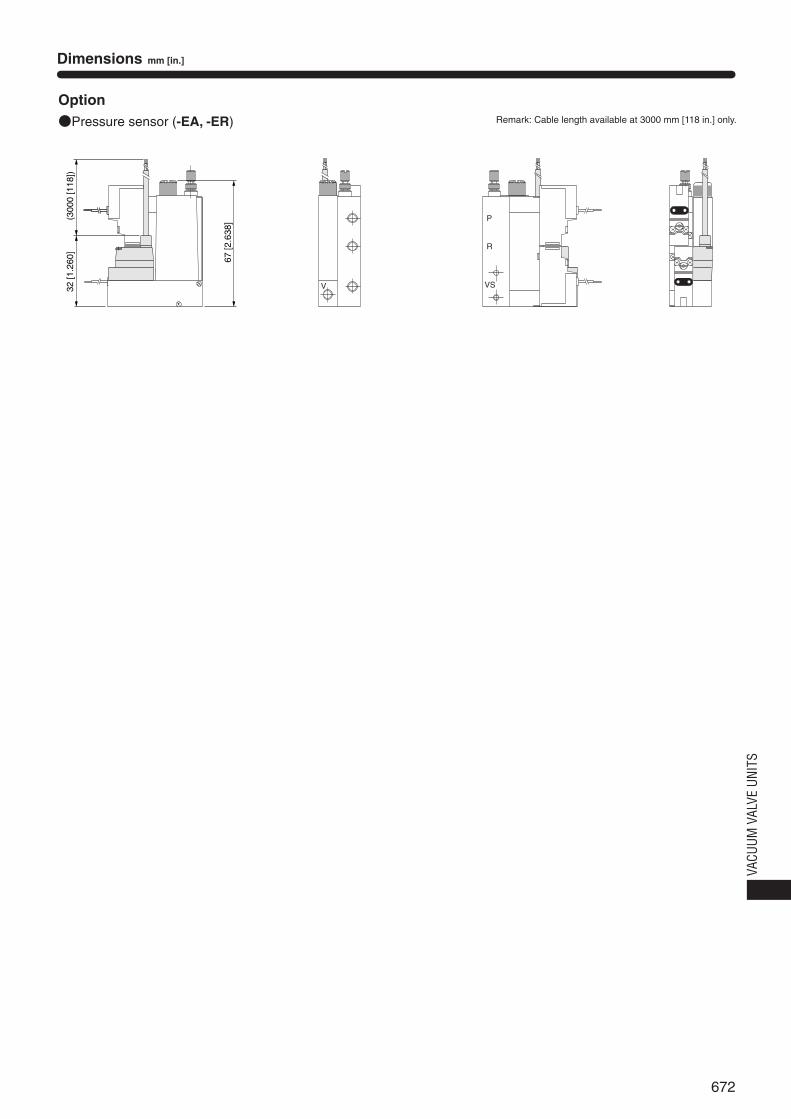
672
VACU
UM V
ALVE
UNI
TS
Dimensions mm [in.]
Option●Pressure sensor (-EA, -ER)
VS
R
P
V32 [1
.260
]
67 [2
.638
](300
0 [1
18])
Remark: Cable length available at 3000 mm [118 in.] only.
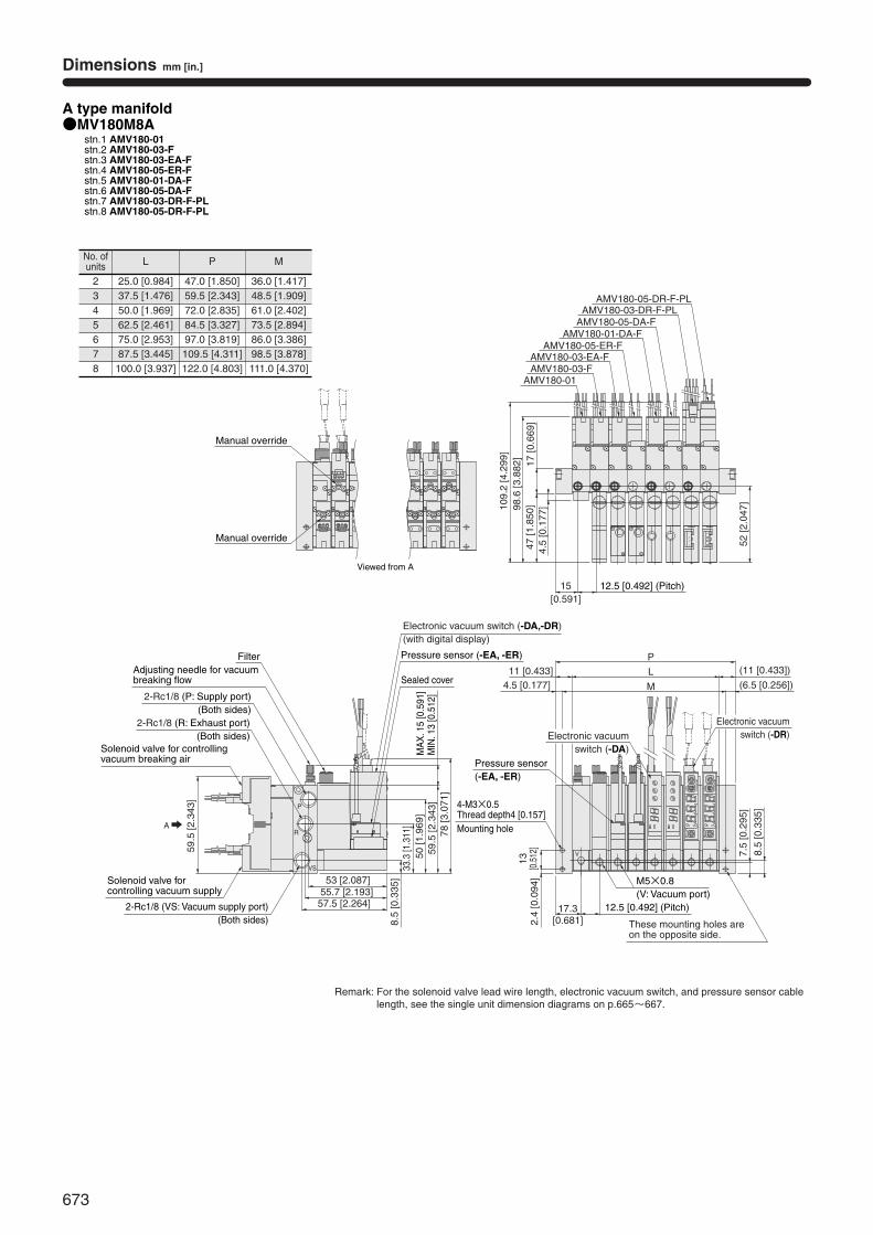
673
●MV180M8Astn.1 AMV180-01stn.2 AMV180-03-Fstn.3 AMV180-03-EA-Fstn.4 AMV180-05-ER-Fstn.5 AMV180-01-DA-Fstn.6 AMV180-05-DA-Fstn.7 AMV180-03-DR-F-PLstn.8 AMV180-05-DR-F-PL
A type manifold
V
KOGANEI
kPa
P2
MV-DRP1
KOGANEI
kPa
P2
MV-DRP1
8.5
[0.3
35]
7.5
[0.2
95]
These mounting holes areon the opposite side.
17.3[0.681]2.
4 [0
.094
]13
[0.5
12]
P11 [0.433] (11 [0.433])L
M
52 [2
.047
]
4.5 [0.177]
59.5
[2.3
43]
8.5
[0.3
35]
33.3
[1.3
11]
50 [1
.969
]59
.5 [2
.343
]78
[3.0
71]
53 [2.087]55.7 [2.193]57.5 [2.264]
A
P
17 [0
.669
]98
.6 [3
.882
]10
9.2
[4.2
99]
4.5
[0.1
77]
(6.5 [0.256])
AMV180-01AMV180-03-FAMV180-03-EA-F
AMV180-05-ER-FAMV180-01-DA-F
AMV180-05-DA-FAMV180-03-DR-F-PL
AMV180-05-DR-F-PL
R
VS
47 [1
.850
]
15[0.591]
Viewed from A
Manual override
Manual override
12.5 [0.492] (Pitch)
Adjusting needle for vacuum breaking flow
Filter
2-Rc1/8 (P: Supply port)(Both sides)
2-Rc1/8 (R: Exhaust port)(Both sides)
Solenoid valve for controlling vacuum breaking air
Solenoid valve for controlling vacuum supply
2-Rc1/8 (VS: Vacuum supply port)(Both sides)
Pressure sensor (-EA, -ER)
Electronic vacuum switch (-DA,-DR)(with digital display)
MA
X. 1
5 [0
.591
]M
IN. 1
3 [0
.512
]
Sealed cover
Pressure sensor(-EA, -ER)
Electronic vacuumswitch (-DA)
Electronic vacuumswitch (-DR)
4-M3×0.5Thread depth4 [0.157] Mounting hole
12.5 [0.492] (Pitch)
M5×0.8(V: Vacuum port)
Dimensions mm [in.]
No. ofunits
2345678
L
25.0 [0.984]37.5 [1.476]50.0 [1.969]62.5 [2.461]75.0 [2.953]87.5 [3.445]100.0 [3.937]
P
47.0 [1.850]59.5 [2.343]72.0 [2.835]84.5 [3.327]97.0 [3.819]109.5 [4.311]122.0 [4.803]
M
36.0 [1.417]48.5 [1.909]61.0 [2.402]73.5 [2.894]86.0 [3.386]98.5 [3.878]111.0 [4.370]
Remark: For the solenoid valve lead wire length, electronic vacuum switch, and pressure sensor cablelength, see the single unit dimension diagrams on p.665~667.
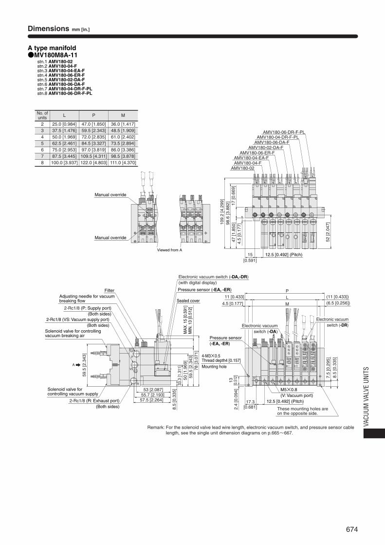
674
VACU
UM V
ALVE
UNI
TS
●MV180M8A-11stn.1 AMV180-02stn.2 AMV180-04-Fstn.3 AMV180-04-EA-Fstn.4 AMV180-06-ER-Fstn.5 AMV180-02-DA-Fstn.6 AMV180-06-DA-Fstn.7 AMV180-04-DR-F-PLstn.8 AMV180-06-DR-F-PL
A type manifold
V
KOGANEI
kPa
P2
MV-DRP1
KOGANEI
kPa
P2
MV-DRP1
P
L
M
52 [2
.047
]
P
AMV180-02AMV180-04-FAMV180-04-EA-F
AMV180-06-ER-FAMV180-02-DA-F
AMV180-06-DA-FAMV180-04-DR-F-PL
AMV180-06-DR-F-PL
R
VS
Viewed from A
Manual override
Manual override
17 [0
.669
]98
.6 [3
.882
]10
9.2
[4.2
99]
4.5
[0.1
77]
47 [1
.850
]
15[0.591]
12.5 [0.492] (Pitch)
Adjusting needle for vacuum breaking flow
Filter
2-Rc1/8 (P: Supply port)(Both sides)
2-Rc1/8 (R: Exhaust port)(Both sides)
Solenoid valve for controlling vacuum breaking air
2-Rc1/8 (VS: Vacuum supply port)(Both sides)
59.5
[2.3
43]
A
Solenoid valve for controlling vacuum supply
53 [2.087]55.7 [2.193]57.5 [2.264]
8.5
[0.3
35]
33.3
[1.3
11]
50 [1
.969
]59
.5 [2
.343
]78
[3.0
71]
Pressure sensor (-EA, -ER)
Electronic vacuum switch (-DA,-DR)(with digital display)
MA
X. 1
5 [0
.591
]M
IN. 1
3 [0
.512
]
Sealed cover11 [0.433] (11 [0.433])
4.5 [0.177] (6.5 [0.256])
Pressure sensor(-EA, -ER)
Electronic vacuumswitch (-DA)
Electronic vacuumswitch (-DR)
2.4
[0.0
94]
13[0
.512
]
4-M3×0.5Thread depth4 [0.157] Mounting hole
These mounting holes areon the opposite side.
17.3[0.681]
12.5 [0.492] (Pitch)
M5×0.8(V: Vacuum port)
8.5
[0.3
35]
7.5
[0.2
95]
Dimensions mm [in.]
No. ofunits
2345678
L
25.0 [0.984]37.5 [1.476]50.0 [1.969]62.5 [2.461]75.0 [2.953]87.5 [3.445]100.0 [3.937]
P
47.0 [1.850]59.5 [2.343]72.0 [2.835]84.5 [3.327]97.0 [3.819]109.5 [4.311]122.0 [4.803]
M
36.0 [1.417]48.5 [1.909]61.0 [2.402]73.5 [2.894]86.0 [3.386]98.5 [3.878]111.0 [4.370]
Remark: For the solenoid valve lead wire length, electronic vacuum switch, and pressure sensor cablelength, see the single unit dimension diagrams on p.665~667.
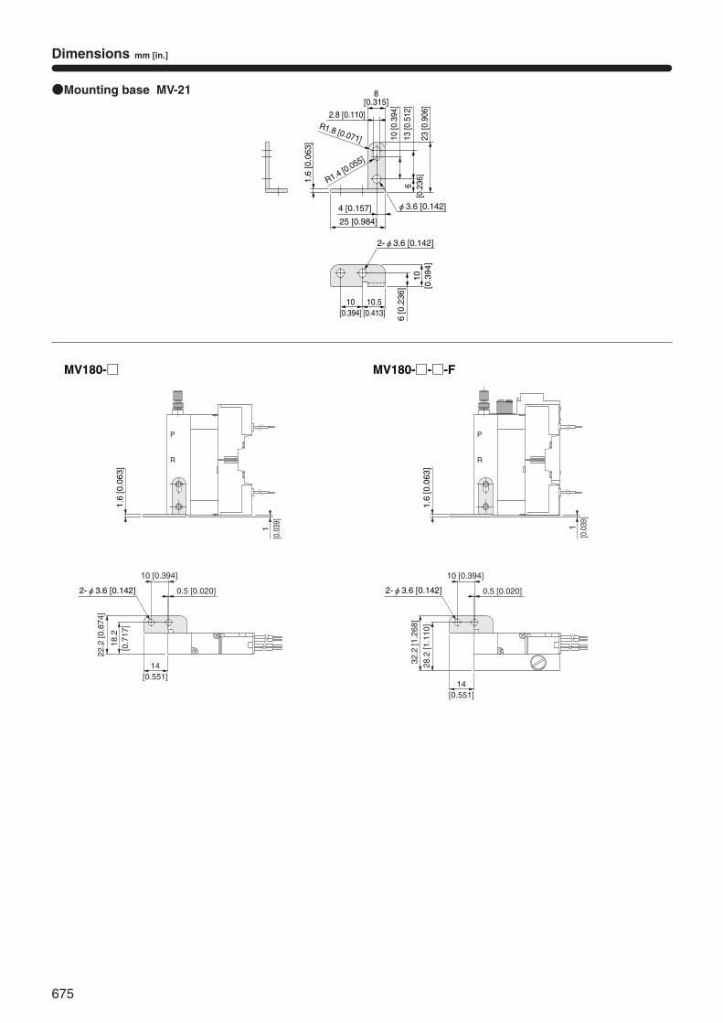
675
Dimensions mm [in.]
R1.4 [0.055]
1.6
[0.0
63]
●Mounting base MV-21
R1.8 [0.071]
2.8 [0.110]
8[0.315]
10 [0
.394
]
23 [0
.906
]
13 [0
.512
]6
[0.2
36]
25 [0.984]
4 [0.157] φ3.6 [0.142]
10[0.394]
10.5[0.413]
10[0
.394
]
6 [0
.236
]
2-φ3.6 [0.142]
R
P1.
6 [0
.063
]
1[0
.039
]
28.2
[1.1
10]
32.2
[1.2
68]
R
P
1[0
.039
]
1.6
[0.0
63]
2-φ3.6 [0.142]
10 [0.394]
0.5 [0.020]
14[0.551]
18.2
[0.7
17]
22.2
[0.8
74]
MV180-□ MV180-□-□-F
2-φ3.6 [0.142]
10 [0.394]
0.5 [0.020]
14[0.551]
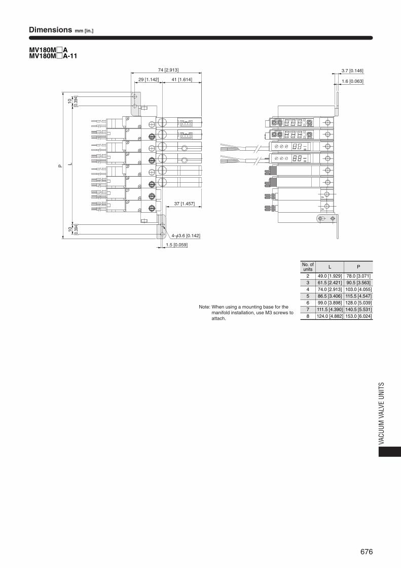
676
VACU
UM V
ALVE
UNI
TS
Dimensions mm [in.]
MV180M□AMV180M□A-11
VV
KOGANEI
kPa
P2
MV-DRP1
KOGANEI
kPa
P2
MV-DRP1
3.7 [0.146]
1.6 [0.063]
P L
37 [1.457]
29 [1.142] 41 [1.614]
74 [2.913]
4-φ3.6 [0.142]
1.5 [0.059]
10[0
.394
]10
[0.3
94]
Note: When using a mounting base for themanifold installation, use M3 screws toattach.
No. ofunits
2345678
L
49.0 [1.929]61.5 [2.421]74.0 [2.913]86.5 [3.406]99.0 [3.898]111.5 [4.390]124.0 [4.882]
P
78.0 [3.071]90.5 [3.563]
103.0 [4.055]115.5 [4.547]128.0 [5.039]140.5 [5.531]153.0 [6.024]
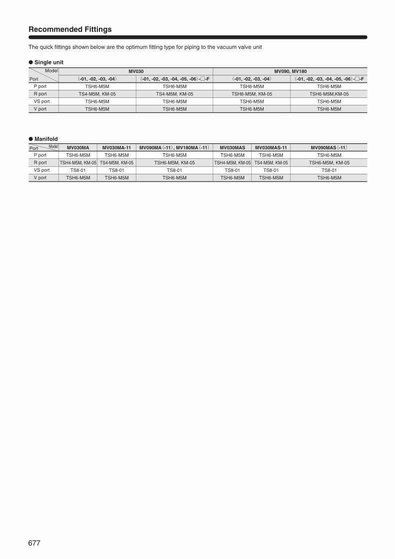
677
Recommended Fittings
● Single unit
● Manifold
MV030
(-01, -02, -03, -04)
TSH6-M5M
TS4-M5M, KM-05
TSH6-M5M
TSH6-M5M
P port
R port
VS port
V port
Port
Model
(-01, -02, -03, -04, -05, -06)-□-F
TSH6-M5M
TS4-M5M, KM-05
TSH6-M5M
TSH6-M5M
MV090, MV180
(-01, -02, -03, -04)
TSH6-M5M
TSH6-M5M, KM-05
TSH6-M5M
TSH6-M5M
(-01, -02, -03, -04, -05, -06)-□-F
TSH6-M5M
TSH6-M5M,KM-05
TSH6-M5M
TSH6-M5M
MV030MA
TSH6-M5M
TSH4-M5M, KM-05
TS8-01
TSH6-M5M
MV030MA-11
TSH6-M5M
TS4-M5M, KM-05
TS8-01
TSH6-M5M
P port
R port
VS port
V port
MV030MAS
TSH6-M5M
TSH4-M5M, KM-05
TS8-01
TSH6-M5M
MV030MAS-11
TSH6-M5M
TS4-M5M, KM-05
TS8-01
TSH6-M5M
MV090MAS(-11)
TSH6-M5M
TSH6-M5M, KM-05
TS8-01
TSH6-M5M
MV090MA(-11), MV180MA(-11)
TSH6-M5M
TSH6-M5M, KM-05
TS8-01
TSH6-M5M
The quick fittings shown below are the optimum fitting type for piping to the vacuum valve unit
Port Model