Embed Size (px)
Citation preview
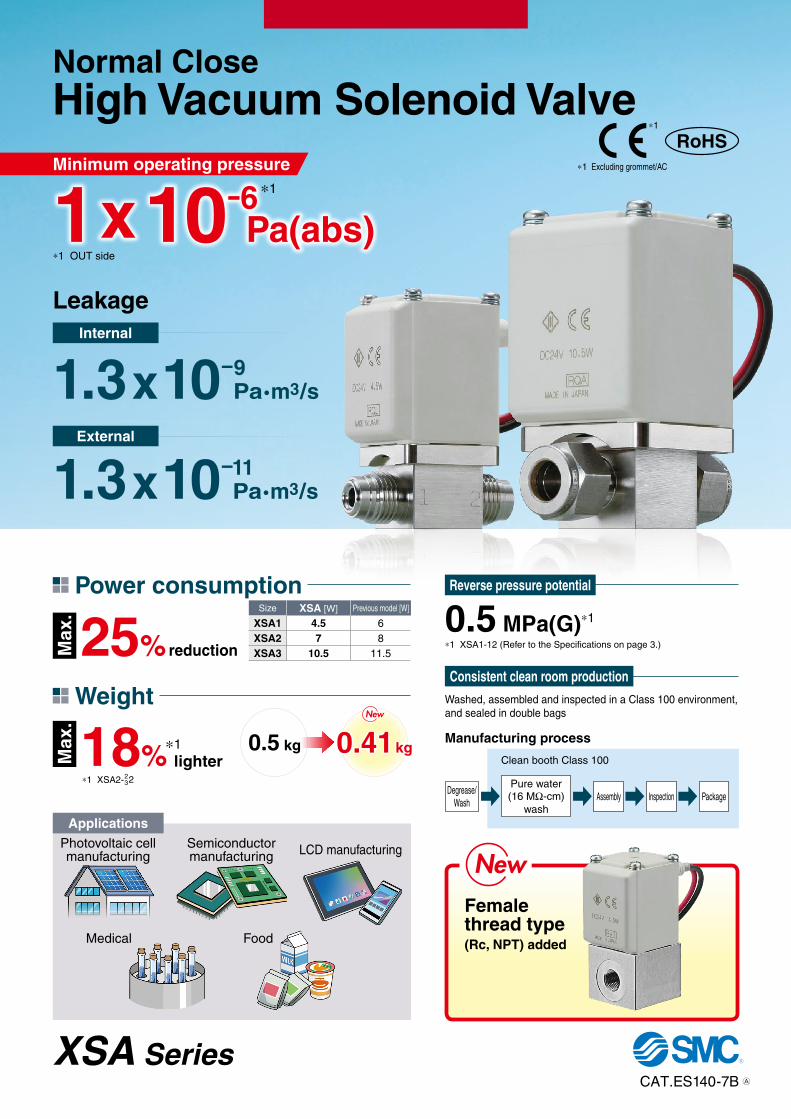
Photovoltaic cell manufacturing
Semiconductor manufacturing LCD manufacturing
Medical Food
Reverse pressure potential
*1 XSA1-12 (Refer to the Specifications on page 3.)
Applications
0.5 MPa(G)*1
NewNewFemale thread type(Rc, NPT) added
25% reductionMax
.M
ax.
Size XSA [W] Previous model [W]
XSA1 4.5 6XSA2 7 8XSA3 10.5 11.5
Power consumption
18%*1 XSA2-2
32
Weight
0.5 kg 0.41 kglighter
*1
NewNew
Consistent clean room productionWashed, assembled and inspected in a Class 100 environment, and sealed in double bags
Manufacturing process
Degrease/Wash
Pure water(16 MΩ-cm)
washAssembly Inspection Package
Clean booth Class 100
CAT.ES140-7B
XSA Series
Normal CloseHigh Vacuum Solenoid ValveMinimum operating pressure
Internal
External
1.3x10⁻⁹Pa·m3/s
1.3x10⁻¹¹Pa·m3/s
Leakage
*1 OUT side
1x10⁻⁶Pa(abs)
*1
*1 Excluding grommet/AC
*1
RoHS
A
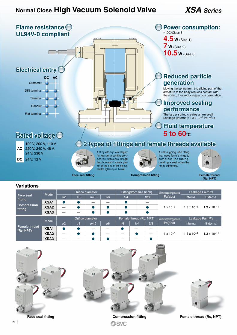
Face seal fitting Compression fitting
A self-aligning tube fitting that uses ferrule rings to compress the tubing, creating a seal when the nut is tightened.
A fitting with high leak integrity for vacuum to positive pres-sure, that forms a seal through the placement of a metal gas-ket at the end of the sleeve and the tightening of the nut.
Female thread(Rc, NPT)
2 types of fittings and female threads available2 types of fittings and female threads available
Electrical entryElectrical entryACDC
Grommet
Flat terminal
Conduit
Terminal
DIN terminal
Flame resistanceUL94V-0 compliantFlame resistanceUL94V-0 compliant
Power consumption:
4.5 W (Size 1)
7 W (Size 2)
10.5 W (Size 3)
∗ DC/Class B
Reduced particlegenerationReduced particlegenerationMoving the spring from the sliding part of the armature to the body reduces contact with the spring, thus reducing particle generation.
Improved sealingperformanceImproved sealingperformanceThe larger spring creates a firm seal!Leakage (Internal): 1.3 x 10⁻⁹ Pa·m3/s
Fluid temperatureFluid temperature5 to 60°C
Variations
Face seal fitting Compression fitting Female thread (Rc, NPT)
Face seal fitting
Compression fitting
ModelOrifice diameter Fitting/Port size (inch) Minimum operating pressure
Pa(abs)Leakage Pa·m3/s
ø2 ø3 ø4.5 ø6 1/4 3/8 Internal External
XSA1 — — —
1 x 10⁻⁶ 1.3 x 10⁻⁹ 1.3 x 10⁻¹¹XSA2 —
XSA3 — —
Female thread(Rc, NPT)
ModelOrifice diameter Female thread (Rc, NPT) Minimum operating pressure
Pa(abs)Leakage Pa·m3/s
ø2 ø3 ø4.5 ø6 1/8 1/4 3/8 Internal External
XSA1 — — — —
1 x 10⁻⁶ 1.3 x 10⁻⁹ 1.3 x 10⁻¹¹XSA2 — — — —
XSA3 — — — —
Normal Close High Vacuum Solenoid Valve XSA Series
Rated voltage
AC100 V, 200 V, 110 V, 220 V, 240 V, 48 V,24 V, 230 V
DC 24 V, 12 V
1A
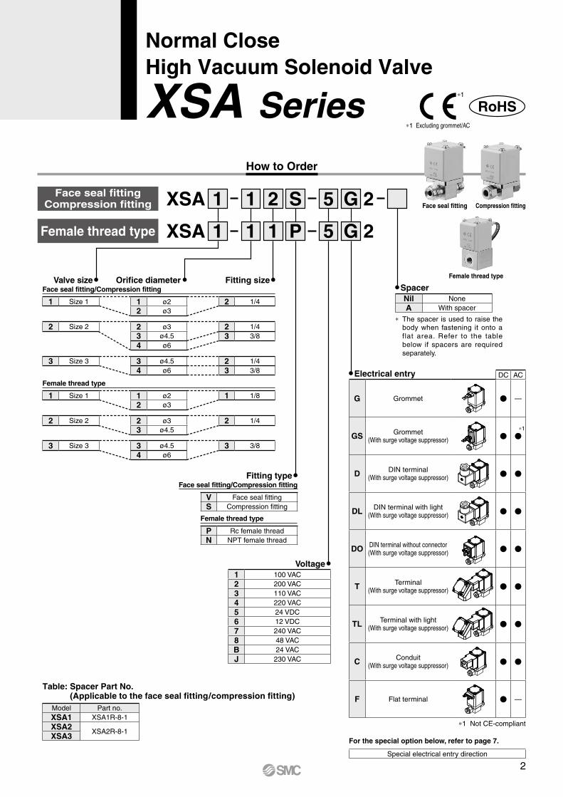
How to Order
XSA
XSA
2
2
1
1
1
1
2
1
S
P
5
5
G
G
Valve sizeFace seal fitting/Compression fitting
Face seal fitting/Compression fitting
Female thread type
Female thread type
Orifice diameter Fitting size
Fitting type
V Face seal fittingS Compression fitting
P Rc female threadN NPT female thread
Voltage1 100 VAC2 200 VAC3 110 VAC4 220 VAC5 24 VDC6 12 VDC7 240 VAC8 48 VACB 24 VACJ 230 VAC
Table: Spacer Part No.(Applicable to the face seal fitting/compression fitting)
Model Part no.XSA1 XSA1R-8-1XSA2
XSA2R-8-1XSA3
1 Size 1 1 ø22 ø3
2 1/4
1 Size 1 1 ø22 ø3
1 1/8
2 Size 2 2 ø33 ø4.54 ø6
2 1/43 3/8
2 Size 2 2 ø33 ø4.5
2 1/4
3 Size 3 3 ø4.54 ø6
2 1/43 3/8
3 Size 3 3 ø4.54 ø6
3 3/8
*1 Excluding grommet/AC
*1
SpacerNil NoneA With spacer
* The spacer is used to raise the body when fastening it onto a flat area. Refer to the table below if spacers are required separately.
DC AC
G Grommet —
GS Grommet(With surge voltage suppressor)
D DIN terminal(With surge voltage suppressor)
DL DIN terminal with light(With surge voltage suppressor)
DO DIN terminal without connector(With surge voltage suppressor)
T Terminal(With surge voltage suppressor)
TL Terminal with light(With surge voltage suppressor)
C Conduit(With surge voltage suppressor)
F Flat terminal —
Electrical entry
For the special option below, refer to page 7.
Special electrical entry direction
*1
*1 Not CE-compliant
XSA Series
Face seal fittingCompression fitting
Female thread type
Face seal fitting Compression fitting
Female thread type
Normal CloseHigh Vacuum Solenoid Valve
2
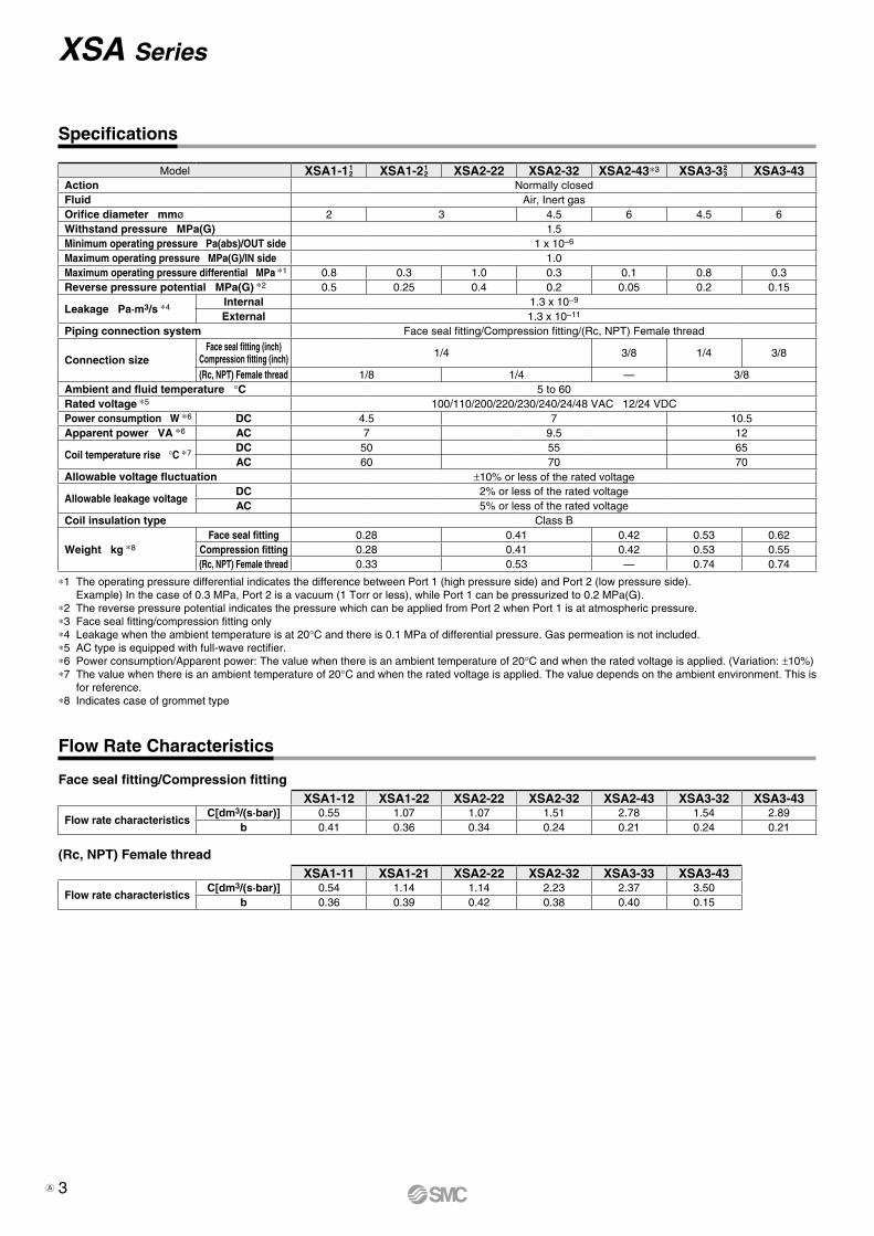
Flow Rate Characteristics
Face seal fitting/Compression fitting
(Rc, NPT) Female thread
XSA1-12 XSA1-22 XSA2-22 XSA2-32 XSA2-43 XSA3-32 XSA3-43
Flow rate characteristicsC[dm3/(s·bar)] 0.55 1.07 1.07 1.51 2.78 1.54 2.89
b 0.41 0.36 0.34 0.24 0.21 0.24 0.21
XSA1-11 XSA1-21 XSA2-22 XSA2-32 XSA3-33 XSA3-43
Flow rate characteristicsC[dm3/(s·bar)] 0.54 1.14 1.14 2.23 2.37 3.50
b 0.36 0.39 0.42 0.38 0.40 0.15
Specifications
*1 The operating pressure differential indicates the difference between Port 1 (high pressure side) and Port 2 (low pressure side).Example) In the case of 0.3 MPa, Port 2 is a vacuum (1 Torr or less), while Port 1 can be pressurized to 0.2 MPa(G).
*2 The reverse pressure potential indicates the pressure which can be applied from Port 2 when Port 1 is at atmospheric pressure.*3 Face seal fitting/compression fitting only*4 Leakage when the ambient temperature is at 20°C and there is 0.1 MPa of differential pressure. Gas permeation is not included.*5 AC type is equipped with full-wave rectifier.*6 Power consumption/Apparent power: The value when there is an ambient temperature of 20°C and when the rated voltage is applied. (Variation: ±10%)*7 The value when there is an ambient temperature of 20°C and when the rated voltage is applied. The value depends on the ambient environment. This is
for reference.*8 Indicates case of grommet type
Model XSA1-11 2 XSA1-21
2 XSA2-22 XSA2-32 XSA2-43*3 XSA3-32 3 XSA3-43
Action Normally closedFluid Air, Inert gasOrifice diameter mmø 2 3 4.5 6 4.5 6Withstand pressure MPa(G) 1.5Minimum operating pressure Pa(abs)/OUT side 1 x 10⁻⁶
Maximum operating pressure MPa(G)/IN side 1.0Maximum operating pressure differential MPa *1 0.8 0.3 1.0 0.3 0.1 0.8 0.3Reverse pressure potential MPa(G) *2 0.5 0.25 0.4 0.2 0.05 0.2 0.15
Leakage Pa·m3/s *4 Internal 1.3 x 10⁻⁹
External 1.3 x 10⁻¹¹
Piping connection system Face seal fitting/Compression fitting/(Rc, NPT) Female thread
Connection sizeFace seal fitting (inch)
Compression fitting (inch) 1/4 3/8 1/4 3/8
(Rc, NPT) Female thread 1/8 1/4 — 3/8Ambient and fluid temperature °C 5 to 60Rated voltage *5 100/110/200/220/230/240/24/48 VAC 12/24 VDCPower consumption W *6 DC 4.5 7 10.5Apparent power VA *6 AC 7 9.5 12
Coil temperature rise °C *7 DC 50 55 65AC 60 70 70
Allowable voltage fluctuation ±10% or less of the rated voltage
Allowable leakage voltageDC 2% or less of the rated voltageAC 5% or less of the rated voltage
Coil insulation type Class B
Weight kg *8Face seal fitting 0.28 0.41 0.42 0.53 0.62
Compression fitting 0.28 0.41 0.42 0.53 0.55(Rc, NPT) Female thread 0.33 0.53 — 0.74 0.74
3
XSA Series
A
q
w
r
t
i
u
oPoppet
e
y
OUT
(Port 2)
IN
(Port 1)
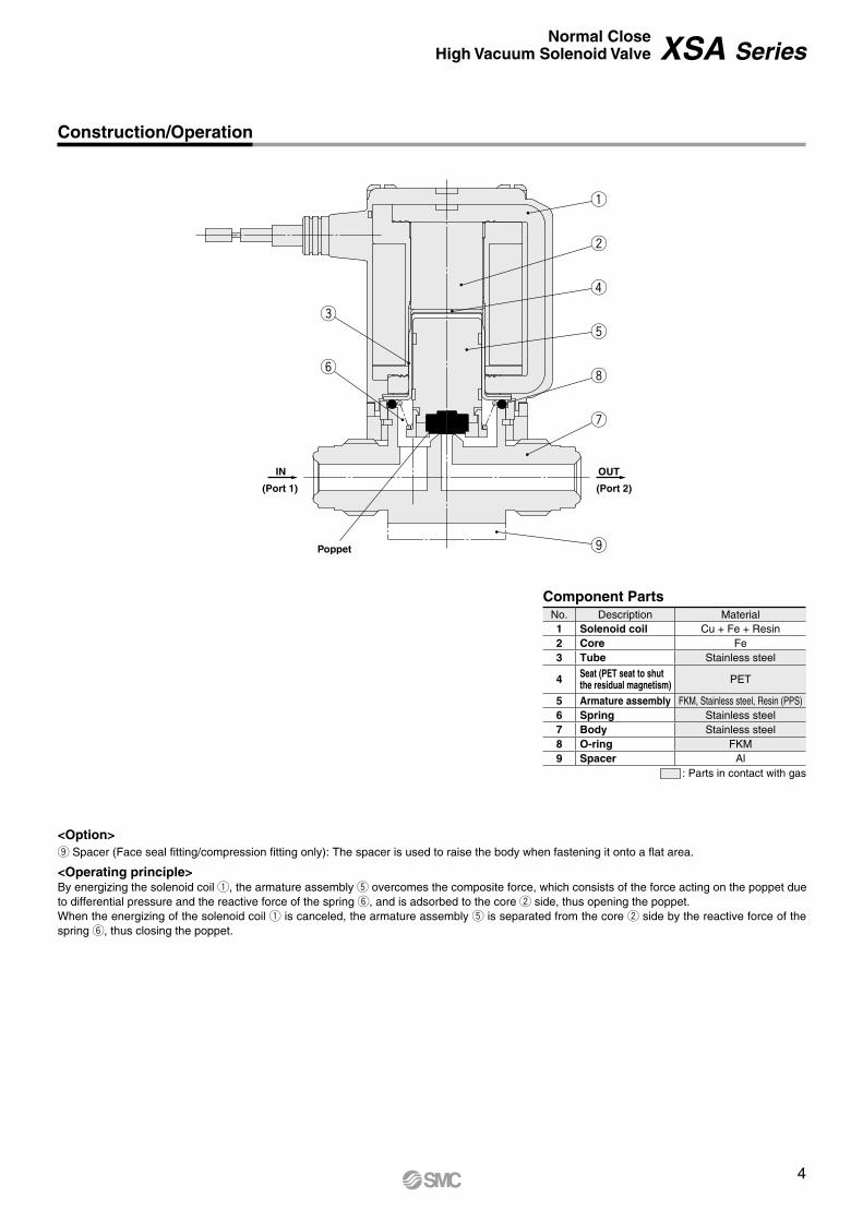
<Option>o� Spacer (Face seal fitting/compression fitting only): The spacer is used to raise the body when fastening it onto a flat area.
<Operating principle>By energizing the solenoid coil q, the armature assembly t overcomes the composite force, which consists of the force acting on the poppet due to differential pressure and the reactive force of the spring y, and is adsorbed to the core w side, thus opening the poppet.When the energizing of the solenoid coil q is canceled, the armature assembly t is separated from the core w side by the reactive force of the spring y, thus closing the poppet.
Construction/Operation
Component PartsNo. Description Material1 Solenoid coil Cu + Fe + Resin2 Core Fe3 Tube Stainless steel
4 Seat (PET seat to shut the residual magnetism) PET
5 Armature assembly FKM, Stainless steel, Resin (PPS)6 Spring Stainless steel7 Body Stainless steel8 O-ring FKM9 Spacer Al
: Parts in contact with gas
4
Normal CloseHigh Vacuum Solenoid Valve XSA Series
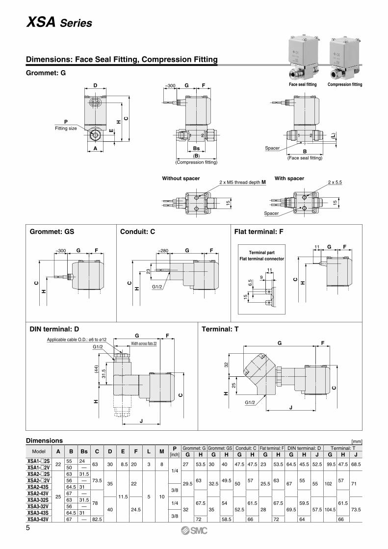
Terminal partFlat terminal connector
211 2
D
PFitting size
CH
A
E
≈300 G F
Bs(B)
(Compression fitting)
B(Face seal fitting)
(L)
Spacer
15
2 x M5 thread depth M
HC
≈300 G F
HC
G1/2
≈280 G FFG11
HC
156.
5
11
9
23
15
Spacer
2 x 5.5Without spacer With spacer
G
25
32
G1/2
H
J
F
C
Width across flats 22
J
31.5
FG
C
(44)
H
G1/2
Applicable cable O.D.: ø6 to ø12
Grommet: G
Terminal: TDIN terminal: D
Grommet: GS Flat terminal: FConduit: C
Dimensions: Face Seal Fitting, Compression Fitting
Face seal fitting Compression fitting
Model A B Bs C D E F L M P[inch]
Grommet: G Grommet: GS Conduit: C Flat terminal: F DIN terminal: D Terminal: TG H G H G H G H G H J G H J
XSA1-2S22
55 2463 30 8.5 20 3 8
1/427 53.5 30 40 47.5 47.5 23 53.5 64.5 45.5 52.5 99.5 47.5 68.5
XSA1-2V 50 —XSA2-2S
25
63 31.573.5
35
11.5
22
5 10
29.563
32.549.5
5057
25.563
6755
55 10257
71XSA2-2V 56 —XSA2-43S 64.5 31
3/8XSA2-43V 67 —
78 67.5 54 61.5 67.5 59.5 61.5XSA3-32S 63 31.5
40 24.51/4
32 35 52.5 28 69.5 57.5 104.5 73.5XSA3-32V 56 —XSA3-43S 64.5 31
3/8XSA3-43V 67 — 82.5 72 58.5 66 72 64 66
Dimensions [mm]
5
XSA Series
21
PFitting size
D
CH
E
A
Q
≈300 G F
B2 x M5 thread depth M
R
HC
≈300 G F
HC
23
≈280 G F
G1/2
156.
5
11
9
HC
11 G F
Applicable cable O.D.: ø6 to ø12G F
Width across flats 22G1/2
31.5(4
4)H
J
C
32H
25
G F
C
JG1/2
Grommet: G
Terminal: TDIN terminal: D
Grommet: GS Flat terminal: FConduit: C
Terminal partFlat terminal connector
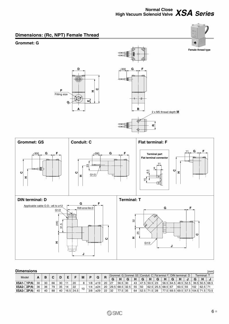
Dimensions: (Rc, NPT) Female Thread
Model A B C D E F M P Q RGrommet: G Grommet: GS Conduit: C Flat terminal: F DIN terminal: D Terminal: TG H G H G H G H G H J G H J
XSA1-1P(N) 30 30 66 30 11 20 8 1/8 ø19 20 27 56.5 30 43 47.5 50.5 23 56.5 64.5 48.5 52.5 99.5 50.5 68.5XSA2-2P(N) 36 36 79 35 14 22
101/4 ø24 20 29.5 68.5 32.5 55 50 62.5 25.5 68.5 67 60.5 55 102 62.5 71
XSA3-3P(N) 40 40 88 40 16.5 24.5 3/8 ø29 22 32 77.5 35 64 52.5 71.5 28 77.5 69.5 69.5 57.5 104.5 71.5 73.5
Dimensions [mm]
Female thread type
6
Normal CloseHigh Vacuum Solenoid Valve XSA Series
A
XSA Series
Special Option/Replacement Parts
¡DIN Connector Part No.
Special Option
Replacement Parts
IN OUT
90°
IN OUT
180°
IN OUT
270°
XSA 2
Enter standard product number.
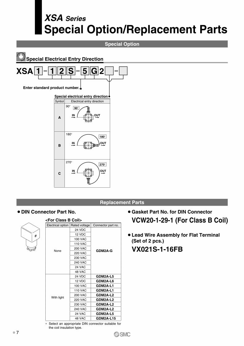
Special Electrical Entry Direction
Special electrical entry direction
21 S 5 G1
Symbol Electrical entry direction
A
90°
B
180°
C
270°
¡Gasket Part No. for DIN Connector
VCW20-1-29-1 (For Class B Coil)
¡Lead Wire Assembly for Flat Terminal(Set of 2 pcs.)
VX021S-1-16FB
<For Class B Coil>
* Select an appropriate DIN connector suitable for the coil insulation type.
Electrical option Rated voltage Connector part no.
None
24 VDC
GDM2A-G
12 VDC
100 VAC
110 VAC
200 VAC
220 VAC
230 VAC
240 VAC
24 VAC
48 VAC
With light
24 VDC GDM2A-L512 VDC GDM2A-L6100 VAC GDM2A-L1110 VAC GDM2A-L1200 VAC GDM2A-L2220 VAC GDM2A-L2230 VAC GDM2A-L2240 VAC GDM2A-L224 VAC GDM2A-L548 VAC GDM2A-L15
7B
R
SOL.
OFFSwitching element
C
Pow
er s
uppl
y
Leakage voltage
Leakage current
4. Countermeasures against static electricityTake measures to prevent static electricity since some fluids can cause static electricity.
XSA SeriesSpecific Product Precautions 1Be sure to read this before handling the products. Refer to the back cover for safety instructions. For common precautions, refer to the “Handling Precautions for SMC Products” and the “Operation Manual” on the SMC website: http://www.smcworld.com
Design
Warning1. Cannot be used as an emergency shutoff valve, etc.
The valve presented in this catalog is not designed for safety applications such as an emergency shutoff valve. If valves are used in this type of system, other reliable safety assurance measures should also be adopted.
2. Extended periods of continuous energizationThe solenoid coil will generate heat when continuously ener-gized. Avoid using in a tightly shut container. Install the valve in a well ventilated area. Furthermore, do not touch it while it is being energized or right after it has been energized.
Selection
Selection
Warning
Warning
1. Fluid1) Type of fluid
Before using a fluid, check whether it is compatible with the materials of each model by referring to the fluids listed in this catalog. (Refer to the Component Parts on page 4.)
2. Fluid quality
<Air>1) Use clean air.
Do not use compressed air that contains chemicals, synthetic oils that include organic solvents, salt, corrosive gases, etc., as it can cause damage or malfunction.
2) Install an air filter, if necessary.Install an air filter close to the valve on the upstream side. A filtration size of 5 μm or smaller should be selected.
3) Install an aftercooler or air dryer, if necessary.Compressed air that contains excessive drainage may cause the malfunction of the valve or other pneumatic equipment. To prevent this, install an aftercooler, air dryer, etc.
4) If excessive carbon powder is generated, eliminate it by installing a mist separator on the upstream side of the valve.If excessive carbon powder is generated by the compressor, it may adhere to the inside of the valve and cause a mal-function.
Refer to “SMC Air Preparation System” for further details on compressed air quality.
<Vacuum>Vacuum piping direction: Connect the piping so that the pressure in the secondary side is lower.Avoid the entry of foreign matter.
3. Ambient environmentUse within the operable ambient temperature range. Check the compatibility between the product’s composition materials and the ambient atmosphere. Be certain that the fluid used does not touch the external surface of the product.
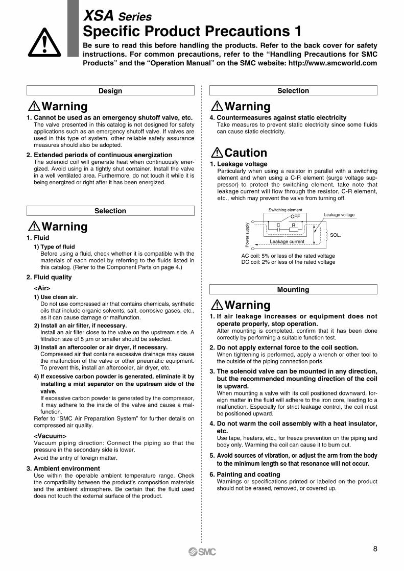
AC coil: 5% or less of the rated voltageDC coil: 2% or less of the rated voltage
Caution1. Leakage voltage
Particularly when using a resistor in parallel with a switching element and when using a C-R element (surge voltage sup-pressor) to protect the switching element, take note that leakage current will flow through the resistor, C-R element, etc., which may prevent the valve from turning off.
Mounting
Warning1. If air leakage increases or equipment does not
operate properly, stop operation.After mounting is completed, confirm that it has been done correctly by performing a suitable function test.
2. Do not apply external force to the coil section.When tightening is performed, apply a wrench or other tool to the outside of the piping connection ports.
3. The solenoid valve can be mounted in any direction, but the recommended mounting direction of the coil is upward.When mounting a valve with its coil positioned downward, for-eign matter in the fluid will adhere to the iron core, leading to a malfunction. Especially for strict leakage control, the coil must be positioned upward.
4. Do not warm the coil assembly with a heat insulator, etc.Use tape, heaters, etc., for freeze prevention on the piping and body only. Warming the coil can cause it to burn out.
5. Avoid sources of vibration, or adjust the arm from the body to the minimum length so that resonance will not occur.
6. Painting and coatingWarnings or specifications printed or labeled on the product should not be erased, removed, or covered up.
8
q
w
Electrical Connections
Caution
Tightening of Female ThreadNPT, Rc1/8 7 to 9 N·mNPT, Rc1/4 12 to 14 N·mNPT, Rc3/8 22 to 24 N·m
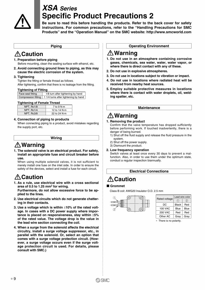
GrommetClass B coil: AWG20 Insulator O.D. 2.5 mm
* There is no polarity.
Rated voltageLead wire color
q w
DC Black Red
100 VAC Blue Blue
200 VAC Red Red
Other AC Gray Gray
XSA SeriesSpecific Product Precautions 2Be sure to read this before handling the products. Refer to the back cover for safety instructions. For common precautions, refer to the “Handling Precautions for SMC Products” and the “Operation Manual” on the SMC website: http://www.smcworld.com
1. Preparation before pipingBefore mounting, clean the sealing surface with ethanol, etc.
2. Avoid connecting ground lines to piping, as this may cause the electric corrosion of the system.
3. TighteningTighten the fitting or female thread as follows.After tightening, confirm that there is no leakage from the fitting.
4. Connection of piping to productsWhen connecting piping to a product, avoid mistakes regarding the supply port, etc.
Tightening of FittingFace seal fitting 1/8 turn after tightening by handCompression fitting 1 1/4 turns after tightening by hand
CautionPiping
Wiring
Warning1. The solenoid valve is an electrical product. For safety,
install an appropriate fuse and circuit breaker before use.When using multiple solenoid valves, it is not sufficient to merely install one fuse on the inlet side. In order to ensure the safety of the devices, select and install a fuse for each circuit.
Operating Environment
Warning1. Do not use in an atmosphere containing corrosive
gases, chemicals, sea water, water, water vapor, or where there is direct contact with any of these.
2. Do not use in explosive atmospheres.3. Do not use in locations subject to vibration or impact.4. Do not use in locations where radiated heat will be
received from nearby heat sources.5. Employ suitable protective measures in locations
where there is contact with water droplets, oil, weld-ing spatter, etc.
Maintenance
Warning1. Removing the product
Confirm that the valve temperature has dropped sufficiently before performing work. If touched inadvertently, there is a danger of being burned.1) Shut off the fluid supply and release the fluid pressure in the
system.2) Shut off the power supply.3) Dismount the product.
2. Low frequency operationSwitch valves at least once every 30 days to prevent a mal-function. Also, in order to use them under the optimum state, conduct a regular inspection biannually.
Caution1. As a rule, use electrical wire with a cross sectional
area of 0.5 to 1.25 mm2 for wiring.Furthermore, do not allow excessive force to be ap-plied to the lines.
2. Use electrical circuits which do not generate chatter-ing in their contacts.
3. Use a voltage which is within ±10% of the rated volt-age. In cases with a DC power supply where impor-tance is placed on responsiveness, stay within ±5% of the rated value. The voltage drop is the value in the lead wire section connecting the coil.
4. When a surge from the solenoid affects the electrical circuitry, install a surge voltage suppressor, etc., in parallel with the solenoid. Or, select an option that comes with a surge voltage protection circuit. (How-ever, a surge voltage occurs even if the surge volt-age protection circuit is used. For details, please consult with SMC.)
9B
Round headcombination screwM3 Tightening torque
0.5 to 0.6 N·m
Round head combination screwM3Tightening torque 0.5 to 0.6 N·m
Terminal cover
A
Conduit terminal
A– M
ark
+ M
ark
G1/2Tightening torque 0.5 to 0.6 N·m
2 (−, +)
1 (+, −)
SOL.
Varistor
2 (−, +)
1 (+, −)
SOL.
Varistor
2 (−, +)
1 (+, −)
SOL.
Light
Varistor
2
1
Rectifierelement
SOL.
Light
Rectifierelement
2
1
Varistor
SOL.
Lead wire
q
Seal
w
2: −(+)
1: +(−)
Compatible cable ∗1
(Cable O.D. ø6 to ø12 mm)Washer
Rubber seal
Binding head screwTightening torque 0.5 to 0.6 N·m
Binding head screw with flangeTightening torque 0.5 to 0.6 N·mConnector
Gasket
XSA SeriesSpecific Product Precautions 3Be sure to read this before handling the products. Refer to the back cover for safety instructions. For common precautions, refer to the “Handling Precautions for SMC Products” and the “Operation Manual” on the SMC website: http://www.smcworld.com
Electrical Connections Electrical Connections
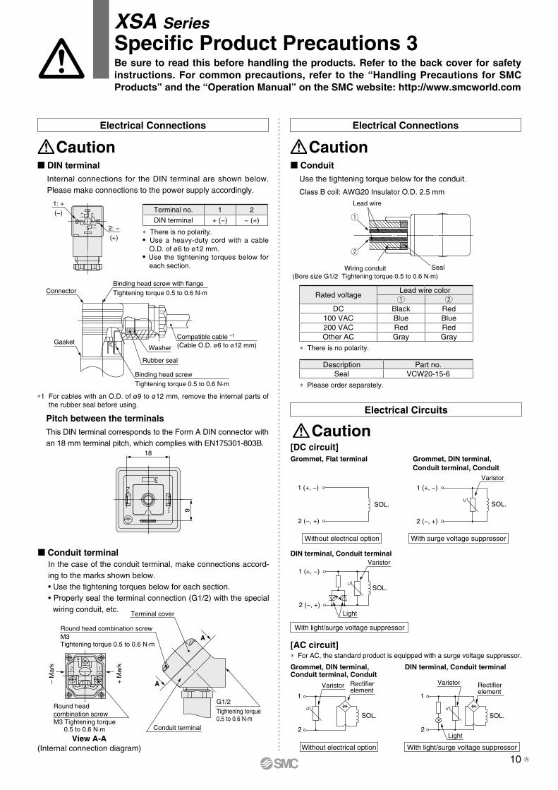
View A-A(Internal connection diagram)
Conduit terminalIn the case of the conduit terminal, make connections accord-ing to the marks shown below.• Use the tightening torques below for each section.• Properly seal the terminal connection (G1/2) with the special
wiring conduit, etc.
Caution Caution
CautionElectrical Circuits
Without electrical option
DIN terminal, Conduit terminalGrommet, DIN terminal,Conduit terminal, Conduit
[AC circuit]
DIN terminal, Conduit terminal
With light/surge voltage suppressor
With light/surge voltage suppressor
With surge voltage suppressor
Grommet, DIN terminal,Conduit terminal, Conduit
Without electrical option
Grommet, Flat terminal
[DC circuit]
* For AC, the standard product is equipped with a surge voltage suppressor.
Pitch between the terminalsThis DIN terminal corresponds to the Form A DIN connector with an 18 mm terminal pitch, which complies with EN175301-803B.
9
18
Class B coil: AWG20 Insulator O.D. 2.5 mm
ConduitUse the tightening torque below for the conduit.
* There is no polarity.
* Please order separately.
Description Part no.Seal VCW20-15-6
Rated voltageLead wire colorq w
DC Black Red100 VAC Blue Blue200 VAC Red RedOther AC Gray Gray
Wiring conduit(Bore size G1/2 Tightening torque 0.5 to 0.6 N·m)
DIN terminalInternal connections for the DIN terminal are shown below. Please make connections to the power supply accordingly.
* There is no polarity.• Use a heavy-duty cord with a cable
O.D. of ø6 to ø12 mm.• Use the tightening torques below for
each section.
Terminal no. 1 2
DIN terminal + (−) − (+)
*1 For cables with an O.D. of ø9 to ø12 mm, remove the internal parts of the rubber seal before using.
10 A
∗ Female thread type added
UZ
Revision History
Edition B
Safety Instructions Be sure to read the “Handling Precautions for SMC Products” (M-E03-3) and “Operation Manual” before use.
CautionSMC products are not intended for use as instruments for legal metrology.Measurement instruments that SMC manufactures or sells have not been qualified by type approval tests relevant to the metrology (measurement) laws of each country. Therefore, SMC products cannot be used for business or certification ordained by the metrology (measurement) laws of each country.
Compliance Requirements
∗1) ISO 4414: Pneumatic fluid power – General rules relating to systems. ISO 4413: Hydraulic fluid power – General rules relating to systems. IEC 60204-1: Safety of machinery – Electrical equipment of machines. (Part 1: General requirements) ISO 10218-1: Manipulating industrial robots – Safety. etc.
Caution indicates a hazard with a low level of risk which, if not avoided, could result in minor or moderate injury.Caution:Warning indicates a hazard with a medium level of risk which, if not avoided, could result in death or serious injury.Warning:
Danger : Danger indicates a hazard with a high level of risk which, if not avoided, will result in death or serious injury.
Warning Caution1. The compatibility of the product is the responsibility of the
person who designs the equipment or decides its specifications.Since the product specified here is used under various operating conditions, its compatibility with specific equipment must be decided by the person who designs the equipment or decides its specifications based on necessary analysis and test results. The expected performance and safety assurance of the equipment will be the responsibility of the person who has determined its compatibility with the product. This person should also continuously review all specifications of the product referring to its latest catalog information, with a view to giving due consideration to any possibility of equipment failure when configuring the equipment.
2. Only personnel with appropriate training should operate machinery and equipment.The product specified here may become unsafe if handled incorrectly. The assembly, operation and maintenance of machines or equipment including our products must be performed by an operator who is appropriately trained and experienced.
3. Do not service or attempt to remove product and machinery/equipment until safety is confirmed.1. The inspection and maintenance of machinery/equipment should only be
performed after measures to prevent falling or runaway of the driven objects have been confirmed.
2. When the product is to be removed, confirm that the safety measures as mentioned above are implemented and the power from any appropriate source is cut, and read and understand the specific product precautions of all relevant products carefully.
3. Before machinery/equipment is restarted, take measures to prevent unexpected operation and malfunction.
4. Contact SMC beforehand and take special consideration of safety measures if the product is to be used in any of the following conditions. 1. Conditions and environments outside of the given specifications, or use
outdoors or in a place exposed to direct sunlight.2. Installation on equipment in conjunction with atomic energy, railways, air
navigation, space, shipping, vehicles, military, medical treatment, combustion and recreation, or equipment in contact with food and beverages, emergency stop circuits, clutch and brake circuits in press applications, safety equipment or other applications unsuitable for the standard specifications described in the product catalog.
3. An application which could have negative effects on people, property, or animals requiring special safety analysis.
4. Use in an interlock circuit, which requires the provision of double interlock for possible failure by using a mechanical protective function, and periodical checks to confirm proper operation.
1. The product is provided for use in manufacturing industries.The product herein described is basically provided for peaceful use in manufacturing industries. If considering using the product in other industries, consult SMC beforehand and exchange specifications or a contract if necessary. If anything is unclear, contact your nearest sales branch.
Limited warranty and Disclaimer/Compliance RequirementsThe product used is subject to the following “Limited warranty and Disclaimer” and “Compliance Requirements”.Read and accept them before using the product.
Limited warranty and Disclaimer1. The warranty period of the product is 1 year in service or 1.5 years after
the product is delivered, whichever is first.∗2)
Also, the product may have specified durability, running distance or replacement parts. Please consult your nearest sales branch.
2. For any failure or damage reported within the warranty period which is clearly our responsibility, a replacement product or necessary parts will be provided. This limited warranty applies only to our product independently, and not to any other damage incurred due to the failure of the product.
3. Prior to using SMC products, please read and understand the warranty terms and disclaimers noted in the specified catalog for the particular products.
∗2) Vacuum pads are excluded from this 1 year warranty.A vacuum pad is a consumable part, so it is warranted for a year after it is delivered. Also, even within the warranty period, the wear of a product due to the use of the vacuum pad or failure due to the deterioration of rubber material are not covered by the limited warranty.
1. The use of SMC products with production equipment for the manufacture of weapons of mass destruction (WMD) or any other weapon is strictly prohibited.
2. The exports of SMC products or technology from one country to another are governed by the relevant security laws and regulations of the countries involved in the transaction. Prior to the shipment of a SMC product to another country, assure that all local rules governing that export are known and followed.
These safety instructions are intended to prevent hazardous situations and/or equipment damage. These instructions indicate the level of potential hazard with the labels of “Caution,” “Warning” or “Danger.” They are all important notes for safety and must be followed in addition to International Standards (ISO/IEC)∗1), and other safety regulations.
Safety Instructions