Embed Size (px)
Citation preview

APPLICATION : AWWA - C512(American Water Works Association)
www.prosave.co.krEnjoy your Job for your Health, with PROSAVE Safety Devices
Saving Danger, More Safe and Better Life
PROSAVE
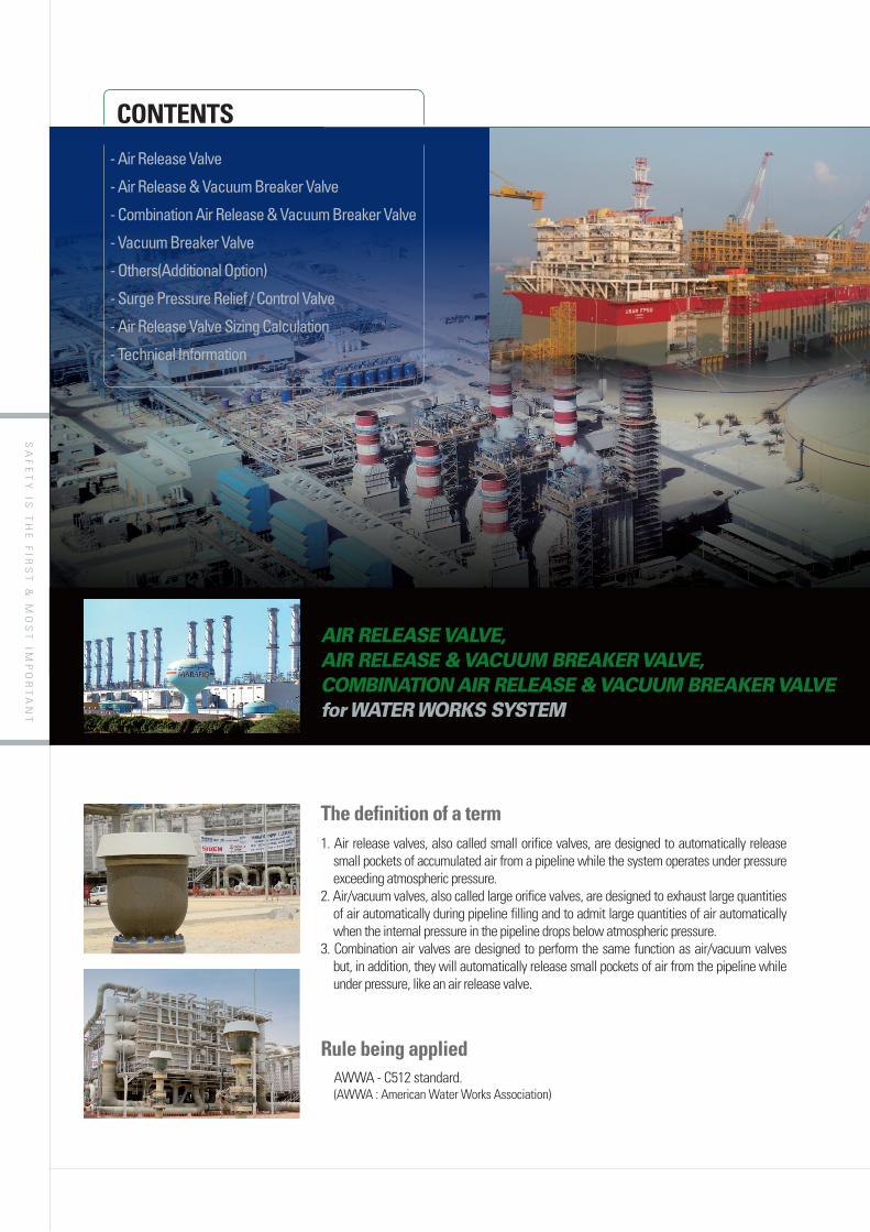
AIR RELEASE VALVE,AIR RELEASE & VACUUM BREAKER VALVE,COMBINATION AIR RELEASE & VACUUM BREAKER VALVEfor WATER WORKS SYSTEM
ARV Series
SA
FE
TY
IS T
HE
FIR
ST
& M
OS
T IM
PO
RT
AN
T1. Air release valves, also called small orifice valves, are designed to automatically release
small pockets of accumulated air from a pipeline while the system operates under pressure exceeding atmospheric pressure.
2. Air/vacuum valves, also called large orifice valves, are designed to exhaust large quantities of air automatically during pipeline filling and to admit large quantities of air automatically when the internal pressure in the pipeline drops below atmospheric pressure.
3. Combination air valves are designed to perform the same function as air/vacuum valves but, in addition, they will automatically release small pockets of air from the pipeline while under pressure, like an air release valve.
AWWA - C512 standard.(AWWA : American Water Works Association)
The definition of a term
Rule being applied
CONTENTS
- Air Release Valve
- Air Release & Vacuum Breaker Valve
- Combination Air Release & Vacuum Breaker Valve
- Vacuum Breaker Valve
- Others(Additional Option)
- Surge Pressure Relief / Control Valve
- Air Release Valve Sizing Calculation
- Technical Information
AIR RELEASE VALVE,AIR RELEASE & VACUUM BREAKER VALVE,COMBINATION AIR RELEASE & VACUUM BREAKER VALVEfor WATER WORKS SYSTEM

SA
FE
TY
IS T
HE
FIR
ST
& M
OS
T IM
PO
RT
AN
T
Enjoy your Job for your Health, with PROSAVE's Safety and Environment Protection Devices
MODEL TYPE OPTION DESCRIPTION ORIFICE REMARK
Standard
AR Air Release Valve Small
KSBJ Air Release & Vacuum Breaker Valve Large
CAV DCombination Air Release & Vacuum Breaker Valve
Dual(Small + large)
Dual Body
CAV S Single Body
Standard+
Option
KSBJ C Air Release & Vacuum Breaker Valve + Surge Check Valve Large
CAV D C Combination Air Release & Vacuum Breaker Valve + Surge Check Valve
Dual(Small + large)
Dual Body
CAV S C Single Body
KSBJ PR Air Release & Vacuum Breaker + Pressure Relief Valve Large
KSBJ PV Air Release & Vacuum Breaker + Pressure & Vacuum Relief Valve Large
KSBJ VB Air Release & Vacuum Breaker + Vacuum Relief Valve Large
KSVB Vacuum Breaker Valve N/A
SRV Surge Pressure Relief Valve N/A
PROSAVE's automatic Air Release Valve series are specifically designed to meet the requirements of water utility systems, greatly improving supply and distribution system efficiency. We place special focus on ensuring that our products meet all applicable standards and specifications prescribed by the industry.From the most complex of applications to the simplest, our automatic Air Release Valve series perform with precision and accuracy to provide exact control of pressure, flow, level, surge and pump control.
Ordering Guide
Safety is our top priority at PROSAVE
Classified Products
Combination Air Release & Vacuum Breaker with Surge Check Valve(Dual Orifice Type, ANSI 150 lb R.F)Material: NI-AL Bronze
SIZE4
MATERIAL5
FLANGE6
MODEL1
TYPE2
OPTION3
EX) CAV - D - C - 04 - B148.C95800 - 150 lb R.F

SA
FE
TY
IS T
HE
FIR
ST
& M
OS
T IM
PO
RT
AN
T
AR MODEL
Materials of Construction
No. DescriptionMaterial
Spec. 1 Spec. 2 Spec. 3
1 Body A216-WCB B148-C95800 A351-CF3M
2 Float & Disc HDPE HDPE HDPE
3 Seat NBR NBR NBR
Introduction
Installation
While the system is flowing and under pressure, air release valves continually and automatically exhaust the small quantities of air that would otherwise collect at system high points.
This ensures the system will remain free of trapped air (and sewage gases) thereby increasing system efficiency and reducing pumping cost.
Air Release valve should be installed at high points or at grade changes within the pipeline.
(exceeding atmospheric pressure)
Benefits
Dimension Table Unit = mm
SIZE 1/2˝ 3/4˝ 1 1 1/2˝ 2˝
N.D 15 20 25 40 50
A 85 85 85 120 150
H 122 122 122 150 200
Note: Standard flange connection is ANSI 150 lb and others are available on request. As per requirement, NPT CONNECTION is available for connection type
A
H
AR
Air Release Valve

SA
FE
TY
IS T
HE
FIR
ST
& M
OS
T IM
PO
RT
AN
T
Enjoy your Job for your Health, with PROSAVE's Safety and Environment Protection Devices
KSBJ MODEL
It is two critical time in the operation of a pipeline.During filling, air that occupies the empty pipe must be evacuated ahead of the incoming liquid in a controlled and efficient manner so that surge and water hammer are minimized and liquid completely fills the pipe. During draining, whether planned or unexpected, air must be admitted into the system to replace the out flowing liquid to avoid excessive vacuum and possible pipeline damage.Air release valve are designed to release accumulated air pockets from the system, while pressured pipelines. Air pockets increase energy consumption because pumping operation will be at higher water heads to overcome pressured air.Air release valves are have function to protect high shock and surge pressure, water hammer and liquid overflow from fresh or sea water pipelines.PROSAVE's valve can provide low cast insurance to protect expensive maintenance cost of pipelines and pump systems.
for pipeline protection
Benefits
H
N.D
ØA
BJ
Activation 1 Pressure Relief
Air intake from ATM.
Water Drain from Pipe
Activation 2 Vacuum Relief
Introduction
Air Discharge to ATM.
Water Drain from Pipe
Activation 3 Liquid Overflow Protection
WaterTight
Water Drainfrom Pipe
NOTICE !!Air Release Valve & Vacuum Breaker Valves can be add another function such as Anti-surge, pressure/vacuum relief in according to operation condition. In this case, You can make good choice PROSAVE's verious model.
Air Release & Vacuum Breaker Valve
Dimension Table Unit = mm
SIZE 1˝ 1 1/2̋ 2̋ 2 1/2̋ 3˝ 4˝ 6˝ 8˝ 10˝ 12˝ 14˝
N.D 25 40 50 65 80 100 150 200 250 300 350
A 170 170 170 210 210 260 340 460 565 635 760
H 235 252 252 272 297 327 392 479 750 845 949
Note: Standard flange connection is ANSI 150 lb and others are available on request.
Materials of Construction
No. DescriptionMaterial
Spec. 1 Spec. 2 Spec. 3
1 Body A216-WCB B148-C95800 A351-CF3M
2 Float & Disc A240-316L MONEL A240-316L
3 Seat NBR NBR NBR

SA
FE
TY
IS T
HE
FIR
ST
& M
OS
T IM
PO
RT
AN
T
Introduction Combination air valves are normally installed at high points where air would naturally rise ahead of the incoming liquid during filling and collect during operation and/or where negative pressure first occurs during draining.
The large (air & vacuum) and the small (air release) orifices are both open during filling with the majority of the air is passes through the large orifice.
The rate at which air is discharged is a function of the differential pressure across the air & vacuum valve.
During filling, incoming water compresses the air in the “empty” pipe until the pressure differential across the air valve is sufficient that air is discharged at the same volumetric rate as water is entering the pipe.
After all the air has been purged, liquid enters the valve and lifts the floats and closes both orifices.
While the large orifice remains closed, the small orifice reopens as necessary to release any air that collects in the valve after it has closed. Should the internal pressure fall below atmospheric, both orifices open to allow air to flow through the valve into the system at the same volumetric rate at which the liquid is draining thus avoiding critical vacuum and damage to the pipe.
Benefits
Combination Air Release & Vacuum Breaker Valve
CAV-D / CAV-S MODEL
Dual Body Single Body
SA
FE
TY
IS T
HE
FIR
ST
& M
OS
T IM
PO
RT
AN
T
Enjoy your Job for your Health, with PROSAVE's Safety and Environment Protection Devices
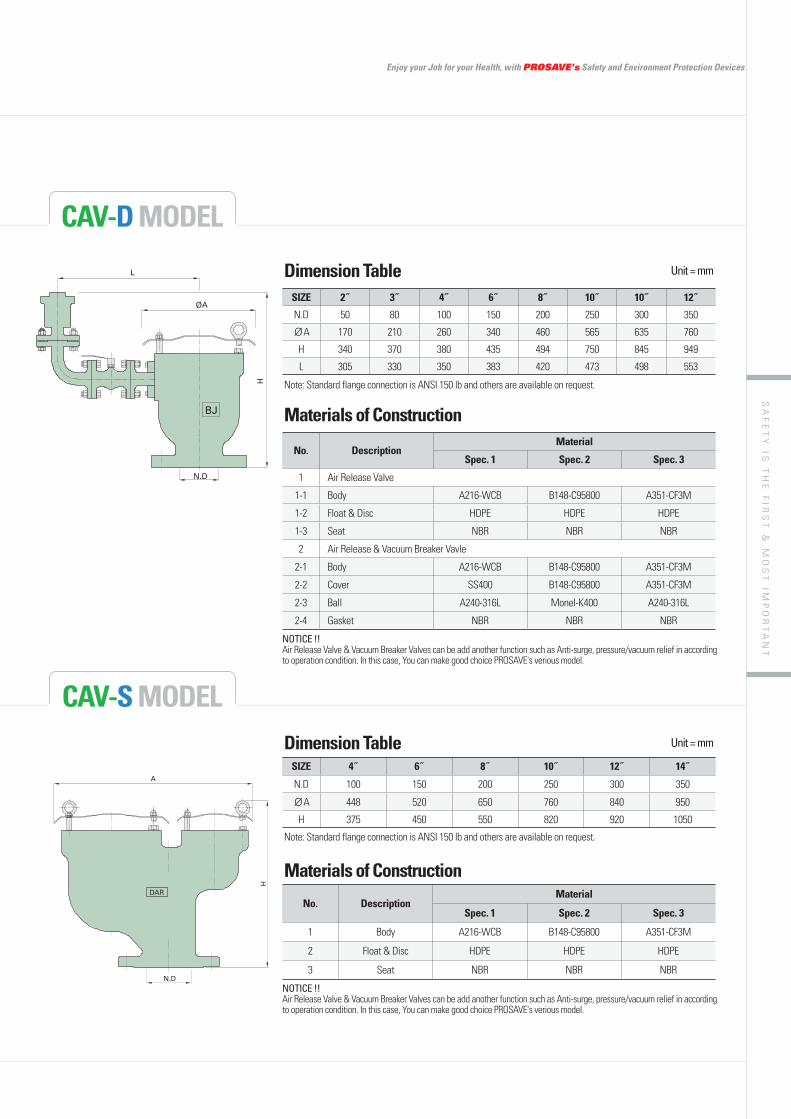
CAV-D MODEL
CAV-S MODEL
L
ØA
H
N.D
BJ
A
H
N.D
DAR
Dimension Table Unit = mm
SIZE 2˝ 3˝ 4˝ 6˝ 8˝ 10˝ 10˝ 12˝
N.D 50 80 100 150 200 250 300 350
A 170 210 260 340 460 565 635 760
H 340 370 380 435 494 750 845 949
L 305 330 350 383 420 473 498 553
Note: Standard flange connection is ANSI 150 lb and others are available on request.
Dimension Table Unit = mm
SIZE 4˝ 6˝ 8˝ 10˝ 12˝ 14˝
N.D 100 150 200 250 300 350
A 448 520 650 760 840 950
H 375 450 550 820 920 1050
Note: Standard flange connection is ANSI 150 lb and others are available on request.
Materials of Construction
No. DescriptionMaterial
Spec. 1 Spec. 2 Spec. 3
1 Air Release Valve
1-1 Body A216-WCB B148-C95800 A351-CF3M
1-2 Float & Disc HDPE HDPE HDPE
1-3 Seat NBR NBR NBR
2 Air Release & Vacuum Breaker Vavle
2-1 Body A216-WCB B148-C95800 A351-CF3M
2-2 Cover SS400 B148-C95800 A351-CF3M
2-3 Ball A240-316L Monel-K400 A240-316L
2-4 Gasket NBR NBR NBR
NOTICE !!Air Release Valve & Vacuum Breaker Valves can be add another function such as Anti-surge, pressure/vacuum relief in according to operation condition. In this case, You can make good choice PROSAVE's verious model.
NOTICE !!Air Release Valve & Vacuum Breaker Valves can be add another function such as Anti-surge, pressure/vacuum relief in according to operation condition. In this case, You can make good choice PROSAVE's verious model.
Materials of Construction
No. DescriptionMaterial
Spec. 1 Spec. 2 Spec. 3
1 Body A216-WCB B148-C95800 A351-CF3M
2 Float & Disc HDPE HDPE HDPE
3 Seat NBR NBR NBR

SA
FE
TY
IS T
HE
FIR
ST
& M
OS
T IM
PO
RT
AN
T
KSVB MODEL
IntroductionThe KSVB is a spring loaded model, designed to handle under pressure with a minimum pressure of -150mmW.C and maximum setting of -7,000mmW.C.
Body material are available in Aluminium, Carbon Steel, 304SS,316SS and Ni-Al Bronze with various trims to suit induvidual requirements.
Sizes range from 50mm through to 300mm with ANSI 150lb FF flanges as standard. (Different connections available on request).
U
Dimension TableSIZE 1˝ 2˝ 3˝ 4˝ 6˝ 8˝ 10˝ 12˝ 16˝ Other Size
N.D 25 50 80 100 150 200 250 300 400
Available on request
A 252 330 440 440 440 550 620 620 650
H 270 333 380 395 405 430 523 558 500
Note: Standard flange connection is ANSI 150 lb and others are available on request.
Materials of Construction
No. DescriptionMaterial
Spec. 1 Spec. 2 Spec. 3
1 Body Carbon Steel Ni-Al Bronze Stainless Steel
2 Vacuum Seat Carbon Steel Ni-Al Bronze Stainless Steel
3 Vacuum Disc Carbon Steel Ni-Al Bronze Stainless Steel
4 Spring A167-316 Inconel A167-316
5 Hood Steel SUS316 SUS316
H
N.D
ØA
Vacuum Breaker Valve
Designed manufactured and tested according to the API 2000 code.
Utilize the latest technologies to provide protection against positive or vacuum over pressure and prevent air intake, evaporative losses of product and
vapours.
Benefits

SA
FE
TY
IS T
HE
FIR
ST
& M
OS
T IM
PO
RT
AN
T
Enjoy your Job for your Health, with PROSAVE's Safety and Environment Protection Devices
Others
Unit = mm
Additional Option for a variety of applications
Combination Air release & Vacuum Breaker with Surge Check Valve
Air release & Vacuum Breaker with Surge Check Valve
Air Release valve with Vacuum Breaker Valve
Air Release & Vacuum Breaker with Pressure / Vacuum Relief Valve
as Combination Air Release & Vacuum Breaker Valve.
as Air Release & Vacuum Breaker Valve.
as air release valves.
of air & small exhaust of air at once
as Air Release & Vacuum Breaker Valve.
and different pressure in pipe line
Benefits
Benefits
Benefits
Benefits
KSBJ-C
CAV-D-CCAV-S-C
AR-VB
KSBJ-VB KSBJ-PR

SA
FE
TY
IS T
HE
FIR
ST
& M
OS
T IM
PO
RT
AN
T
SRV MODEL
INLET OUTLET
TO CONTROL ROOM
SURGE RELIEF VALVEFULL BORE VALVE
Pressure indicator
PIPI
SURGE COMMANDER
TO CONTROL ROOM
Main Pipeline To Overflow Tank or To Discharge
FT
FLOW
Position IndicatorLIMIT S/W
Junction Box
Typical Installation
Surge Pressure Relief / Control Valve
BenefitsThe high-capacity proportional hydraulic design allows fast response to surge pressure. This results in prompt return to stable pressure conditions.
Due to the absence of any external gas supply such as gas bottle, maintenance is reduced to the bare minimum, making the valve ideal for remote or inaccessible locations.
Surge valve designs are based on simplicity. All components are field-proven to provide maximum protection reliability. They operate solely on fluid static pressure.
The design of the hydraulic incorporates snap-acting opening when the set pressure is reached and automatic switching to control in the event of continuing high-pressure conditions.
IntroductionSurge Relief Valves are consists of a main valve assembly and Hydraulic Actuator, Accessory, completely assembled and tested as a unit and ready for field installation.
The valves are open when system pressure exceeds its pressure setting and throttle as necessary to limit system pressure to a pre-set maximum pressure. When pressure subsides below the pre-set maximum the valves are close tight.

SA
FE
TY
IS T
HE
FIR
ST
& M
OS
T IM
PO
RT
AN
T
Enjoy your Job for your Health, with PROSAVE's Safety and Environment Protection Devices
A
H
N.D
FLOW
Position IndicatorLIMIT S/W
1
5
3
7
14
6
2
11
15
8
13
12
17
Junction Box
PRESSURETRANSMETER
SURGE COMMANDEREnclosure : Corrosion resistantDimension : 400(H) x 450(W) x 230(D)Input Power : 24VACOut Power : 24VDC from interal battery, charger
Dimension Table Unit = mm
SIZE 2˝ 3˝ ˝ 6˝ 8˝ 10˝ 12˝ 16˝ 20˝ ˝ Other Size
N.D 50 80 100 150 200 250 300 400 500 600Available on request
A 275 300 375 500 635 744 850 1035 1178 1250
H 800 800 900 1000 1200 1400 1600 1900 2200 2500
Note: Standard flange connection is JIS 5K and others are available on request.
Materials of Construction1 BODY ASTM A216 Gr. WCB
2 BONET(COVER) ASTM A216 Gr. WCB
3 HYDRAULIC ACTUATOR STEEL
5 CYLINER FLANGE PLATE S.S. TYPE 316
6 COUPLING JOINT STEEL COMM'L
7 DISK S.S TYPE 316
8 DISK RETAINER S.S TYPE 316
9 STEM SEAL BUNA-N
11 SEAT RING S.S TYPE 316
12 SPRING STEEL
13 POISITION INDICATOR STEEL COMM'L
14 RESILIENT DISK EPDM
15 STEM S.S TYPE 316
17 SPRING GUIDE STEEL COMM'L
SA
FE
TY
IS T
HE
FIR
ST
& M
OS
T IM
PO
RT
AN
T
Sizing Calculation
Air Release Valve Sizing Calculation
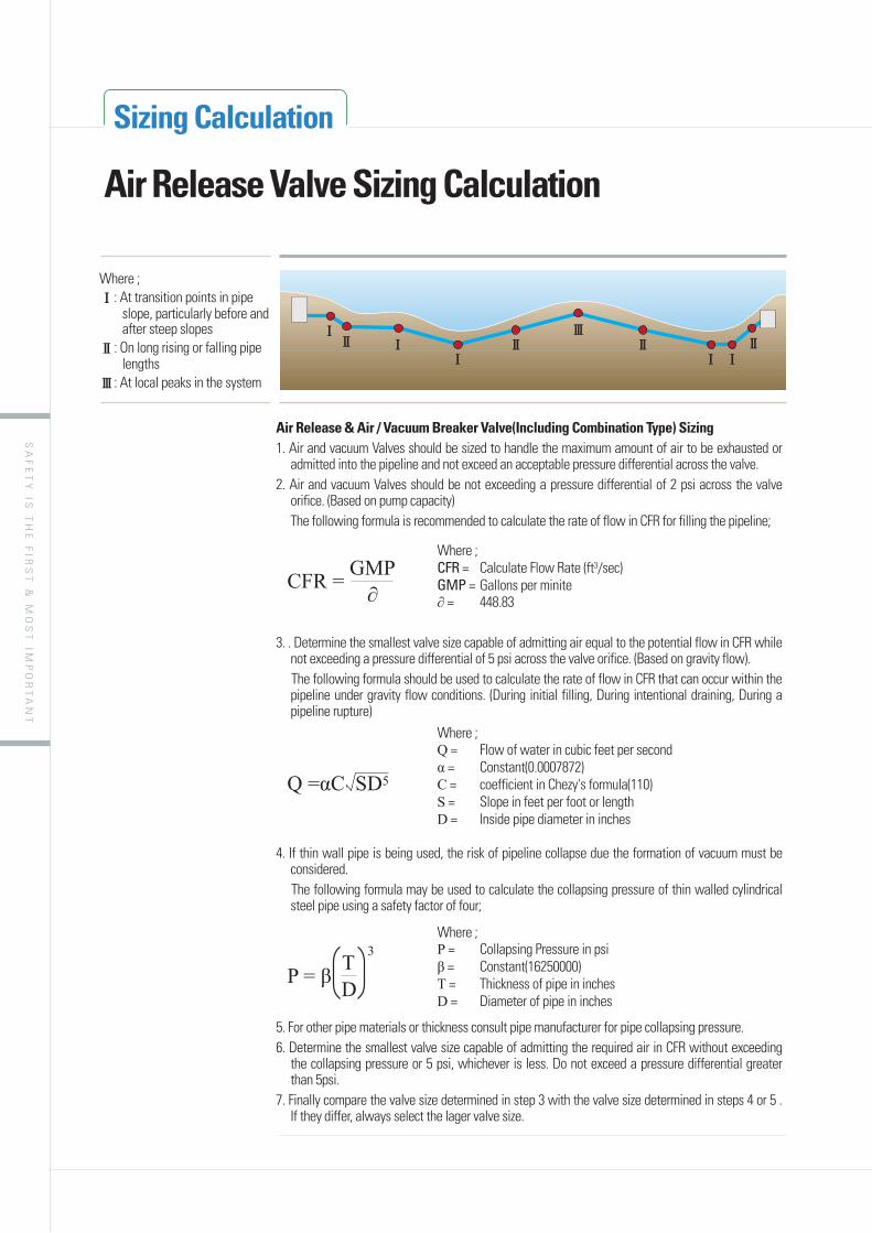
Air Release & Air / Vacuum Breaker Valve(Including Combination Type) Sizing1. Air and vacuum Valves should be sized to handle the maximum amount of air to be exhausted or
admitted into the pipeline and not exceed an acceptable pressure differential across the valve.2. Air and vacuum Valves should be not exceeding a pressure differential of 2 psi across the valve
orifice. (Based on pump capacity) The following formula is recommended to calculate the rate of flow in CFR for filling the pipeline;
3. . Determine the smallest valve size capable of admitting air equal to the potential flow in CFR while not exceeding a pressure differential of 5 psi across the valve orifice. (Based on gravity flow).
The following formula should be used to calculate the rate of flow in CFR that can occur within the pipeline under gravity flow conditions. (During initial filling, During intentional draining, During a pipeline rupture)
4. If thin wall pipe is being used, the risk of pipeline collapse due the formation of vacuum must be considered.
The following formula may be used to calculate the collapsing pressure of thin walled cylindrical steel pipe using a safety factor of four;
5. For other pipe materials or thickness consult pipe manufacturer for pipe collapsing pressure.6. Determine the smallest valve size capable of admitting the required air in CFR without exceeding
the collapsing pressure or 5 psi, whichever is less. Do not exceed a pressure differential greater than 5psi.
7. Finally compare the valve size determined in step 3 with the valve size determined in steps 4 or 5 . If they differ, always select the lager valve size.
Where ;CFR = Calculate Flow Rate (ft3/sec)GMP = Gallons per minite
= 448.83CFR = GMP
Where ; = Flow of water in cubic feet per second = Constant(0.0007872)
C = coefficient in Chezy's formula(110)S = Slope in feet per foot or lengthD = Inside pipe diameter in inches
5
Where ;P = Collapsing Pressure in psi
= Constant(16250000)T = Thickness of pipe in inchesD = Diameter of pipe in inches
TD
3
Where ;Ⅰ: At transition points in pipe
slope, particularly before and after steep slopes
Ⅱ: On long rising or falling pipe lengths
Ⅲ: At local peaks in the system
ⅠⅠ
Ⅰ Ⅰ Ⅰ
ⅢⅡ Ⅱ ⅡⅡ

SA
FE
TY
IS T
HE
FIR
ST
& M
OS
T IM
PO
RT
AN
T
Enjoy your Job for your Health, with PROSAVE's Safety and Environment Protection Devices
Technical Information
Unit Conversion Table● Length
● Area
● Weight
● Pressure
● Flow Rate
mm cm m km inch feet mile
mm 1 0.1 0.0001 0.0000001 0.039370079 0.003280827 0.001093598 6.21164E-07
cm 10 0.01 0.00001 0.393700787 0.032808268 0.01093598 6.21164E-06
m 1000 100 1 0.001 39.37007874 3.280826772 1.093597988 0.000621164
km 1000000 100000 1000 1 39370.07874 3280.826772 1093.597988 0.621163657
inch 25.4 2.54 0.0254 0.0000254 1 0.083333 0.027777389 1.57776E-05
feet 304.8 30.48 0.3048 0.0003048 12 1 0.33333 0.000189331
914.4 91.44 0.9144 0.0009144 36 3 1 0.000568
mile 1609344 160934.4 1609.344 1.609344 63360 5280 1760 1
cm² m² km² in² ft² acre mile²
cm² 1 0.0001 1E-10 0.15500031 0.001076385 1.19596E-06 - -
m² 10000 0.000001 1550.00312 10.76382449 1.195956586 0.000247105 -
km² 10000000000 1000000 1 1550003120 10763824.49 1195956.586 247.105 0.385844342
in² 6.4516 0.00064516 6.4516E-10 1 0.006944389 0.000771584 - -
ft² 929.0304 0.09290304 9.2903E-08 144 1 0.111111111 0.000023 3.58345E-08
8361.2736 0.83612736 8.36127E-07 1296 9 1 0.0002066 3.22624E-07
acre - 4046.86 0.004047 - 43560 4840 1 0.001562
mile² 25899881103 2589988.11 2.58998811 4014489600 27878400 3097600 640 1
atmos mm·Hg m·bar bar pascal in H2O in Hg psi
atmos 1 760 1013.25 1.01325 101325 406.781 29.9213 14.6959
mm·Hg 0.0013158 1.33322 0.001333 133.322 0.53524 0.03937 0.019337
m·bar 0.0009869 0.750062 1 0.001 100 0.401463 0.02953 0.014504
bar 0.9869 750.062 1000 1 100000 401.463 29.53 14.504
pascal 0.0000099 0.007501 0.01 0.00001 1 0.004015 0.0002953 0.000145
in H2O 0.0024583 1.86832 2.49089 0.002491 249.089 1 0.073556 0.036127
in Hg 0.033421 25.4 33.8639 0.0338639 3386.39 13.5951 1 0.491154
psi 0.068046 51.7149 68.9476 0.0689476 6894.76 27.6799 2.03602 1
L/s L/min cm3/s m3/hr ft3/min gal/min
L/s 1 60 1000 3.6 2.11887 15.851
L/min 0.016667 1 16.6667 0.06 0.035314 0.26418
cm3/s 0.001 0.06 1 0.0036 0.002119 0.01585
m3/hr 0.277778 16.6667 277.778 1 0.588575 4.40295
ft3/min 0.47195 28.317 471.95 1.69902 1 7.4807
gal/min 0.063089 3.78534 63.089 0.22712 .0.131677 1
kg ton lb UK cwt UK ton US cwt US ton
kg 1 0.001 2.20462 0.019684 0.000984 0.022046 0.001102
ton 1 2204.62 19.6841 0.984207 22.0462 1.10231
lb 0.453592 0.000453592 1 0.008929 0.000446 0.01 0.0005
UK cwt 50.8023 0.0508023 112 1 0.05 1.12 0.056
UK ton 1016.05 1.01605 2240 20 1 22.4 1.12
US cwt 45.3592 0.045359 100 0.892857 0.044643 1 0.05
US ton 907.185 0.907185 2000 17.8571 0.892857 20 1

SA
FE
TY
IS T
HE
FIR
ST
& M
OS
T IM
PO
RT
AN
T
FluidMetal
Carbon Steel Cast Iron 302 and 304 Stainless Steel
316 Stainless Steel Bronze Alloy20 Monel Hasteloy B Hasteloy C Titanium Cobalt base alloy
6416 Stainless
Steel
Acetaldehyde 1 1 1 1 1 1 1 na 1 na na 1
Acetic acid, air free 3 3 2 2 2 1 2 1 1 1 1 3
Acetic acid, aerated 3 3 1 1 1 1 1 1 1 1 1 3
Acetic acid, vapors 3 3 1 1 2 2 2 na 1 1 1 3
Acetone 1 1 1 1 1 1 1 1 1 1 1 1
Acetylene 1 1 1 1 1 1 1 1 na 1 1
Alcohols 1 1 1 1 1 1 1 1 1 1 1
Aluminum Sulfate 3 3 1 1 2 1 2 1 1 1 na 3
Ammonia 1 1 1 1 3 1 3 1 1 1 1 1
Ammonium chloride 3 3 2 2 2 1 2 1 1 1 2 3
Ammonium Nitrate 1 3 1 1 3 1 3 1 1 1 1 3
Ammonium Phosphate 4 3 1 1 2 2 2 1 1 1 1 2
Ammonium Sulfate 3 3 2 1 2 1 1 1 1 1 1 3
Ammonium Sulfite 3 3 1 1 3 1 3 na 1 1 1 2
Aniline 3 3 1 1 3 1 2 1 1 1 1 3
Asphalt 1 1 1 1 1 1 1 1 1 na 1 1
Beer 2 2 1 1 2 1 1 1 1 1 1 2
Benzene (benzol) 1 1 1 1 1 1 1 1 1 1 1 1
Benzoic acid 3 3 1 1 1 1 1 1 1 1
Boric acid 3 3 1 1 1 1 1 1 1 1 1 2
Butane 1 1 1 1 1 1 1 1 1 1 1
Calcium Chloride (alkaline) 2 2 3 2 3 1 1 1 1 1 na 3
Calcium hypochlorite 3 3 2 2 2 1 2 3 1 1 na 3
Carbolic acid 2 2 1 1 1 1 1 1 1 1 1
Carbon dioxide, dry 1 1 1 1 1 1 1 1 1 1 1 1
Carbon dioxide, wet 3 3 1 1 2 1 1 1 1 1 1 1
Carbon disulfide 1 1 1 1 3 1 2 1 1 1 1 2
Carbon tetrachloride 2 2 2 2 1 1 1 2 1 1 na 3
Carbonic acid 3 3 2 2 2 1 1 1 1 1
Chlorine gas 1 1 2 2 2 1 1 1 1 3 2 3
Chlorine gas, wet 3 3 3 3 3 3 3 3 2 1 2 3
Chlorine, liquid 3 3 3 3 2 2 3 3 1 3 2 3
Chromic acid 3 3 3 2 3 3 1 3 1 1 2 3
Citric acid 3 2 1 1 1 2 1 1 1 2
Coke oven gas 1 1 1 1 2 1 2 1 1 1 1 1
Copper sulfate 3 3 2 2 2 1 3 na 1 1 na 1
Cottonseed oil 1 1 1 1 1 1 1 1 1 1 1 1
Creosote 1 1 1 1 3 1 1 1 1 1 1
Ethane 1 1 1 1 1 1 1 1 1 1 1 1
Ether 2 2 1 1 1 1 1 1 1 1 1 1
Ethyl chloride 3 3 1 1 1 1 1 1 1 1 1 2
Ethylene 1 1 1 1 1 1 1 1 1 1 1 1
Ethylene glycol 1 1 1 1 1 1 1 na na na 1 1
Ferric chloride 3 3 3 3 3 3 3 3 2 1 2 3
Formaldehyde 2 2 1 1 1 1 1 1 1 1 1 1
Formic acid 3 2 2 1 1 1 1 1 3 2 3
Freon wet 2 2 2 1 1 1 1 1 1 1 1 na
Freon dry 2 2 1 1 1 1 1 1 1 1 1 na
Furfural 1 1 1 1 1 1 1 1 1 1 1 2
Gasoline 1 1 1 1 1 1 1 1 1 1 1 1
Glucose 1 1 1 1 1 1 1 1 1 1 1 1
Hydrochloric acid, aerated 3 3 3 3 3 3 3 1 2 1-2 2 3
Hydrochloric acid, air free 3 3 3 3 3 3 3 1 2 1-2 2 3
Technical InformationRating Explanation
1 2
3 na
Good Be careful
Not useable No informationCorrosion Resistance Table

SA
FE
TY
IS T
HE
FIR
ST
& M
OS
T IM
PO
RT
AN
T
Enjoy your Job for your Health, with PROSAVE's Safety and Environment Protection Devices
FluidMetal
Carbon Steel Cast Iron 302 and 304 Stainless Steel
316 Stainless Steel Bronze Alloy20 Monel Hasteloy B Hasteloy C Titanium Cobalt base alloy
6416 Stainless
Steel
Hydrofluoric acid, aerated 2 3 3 2 3 2 3 1 1 3 2 3
Hydrofluoric acid, air free 1 3 3 2 3 2 1 1 1 3 na 3
Hydrogen 1 1 1 1 1 1 1 1 1 1 1 1
Hydrogen peroxide 1 1 1 3 1 3 2 2 1 na 2
Hydrogen sulfide, liquid 3 3 1 1 3 2 3 1 1 1 1 3
Magnesium Hydroxide 1 1 1 1 2 1 1 1 1 1 1 1
Mercury 1 1 1 1 3 1 2 1 1 1 1 1
Methanol 1 1 1 1 1 1 1 1 1 1 1 1
Methyl ethyl ketone 1 1 1 1 1 1 1 1 1 1 1
Milk 3 3 1 1 1 1 1 1 1 1 1 3
Natural gas 1 1 1 1 1 1 1 1 1 1 1 1
Nitric acid 3 3 1 2 3 1 3 3 2 1 3 3
Oleic acid 3 3 1 1 2 1 1 1 1 1 1 1
Oxalic acid 3 3 2 2 2 1 2 1 1 2 2 2
Oxygen 1 1 1 1 1 1 1 1 1 1 1 1
Petroleum oils 1 1 1 1 1 1 1 1 1 1 1 1
Phosphoric acid, aerated 3 3 1 1 3 1 3 1 1 2 1 3
Phosphoric acid, air free 3 3 1 1 3 1 2 1 1 2 1 3
Phosphoric acid vapors 3 3 2 2 3 1 3 1 2 3 3
Picric acid 3 3 1 1 3 1 3 1 1 na na 2
Potassium chloride 2 2 1 1 2 1 2 1 1 1 na 3
Potassium hydroxide 2 2 1 1 2 1 1 1 1 1 na 2
Propane 1 1 1 1 1 1 1 1 1 1 1 1
Rosin 2 2 1 1 1 1 1 1 1 1 1
Silver Nitrate 3 3 1 1 3 1 3 1 1 1 2 2
Sodium acetate 1 1 2 1 1 1 1 1 1 1 1 1
Sodium carbonate 1 1 1 1 1 1 1 1 1 1 1 2
Sodium chloride 3 3 2 2 1 1 1 1 1 1 1 2
Sodium chromate 1 1 1 1 1 1 1 1 1 1 1 1
Sodium hydroxide 1 1 1 1 3 1 1 1 1 1 1 2
Sodium hypochloride 3 3 3 3 3 2 3 3 1 1 na 3
Sodium thiosulfate 3 3 1 1 3 1 3 1 1 1 na 2
Stannous chloride 2 2 3 1 3 1 2 1 1 1 na 3
Stearic acid 1 3 1 1 2 1 2 1 1 1 2 2
Sulfate liquor 1 1 1 1 3 1 1 1 1 1 1
Sulfur 1 1 1 1 3 1 1 1 1 1 1 1
Sulfur dioxide, dry 1 1 1 1 1 1 1 2 1 1 1 2
Sulfur trioxide, dry 1 1 1 1 1 1 1 2 1 1 1 2
Sulfuric acid, aerated 3 3 3 3 3 1 3 1 1 2 2 3
Sulfuric acid, air free 3 3 3 3 2 1 2 1 1 2 2 3
Sulfurous acid 3 3 2 2 2 1 3 1 1 1 2 3
Tar 1 1 1 1 1 1 1 1 1 1 1 1
Trichloroethylene 2 2 2 1 1 1 1 1 1 1 1 2
Turpentine 2 2 1 1 1 1 2 1 1 1 1 1
Vinegar 3 3 1 1 2 1 1 1 1 na 1 3
Water, steam boiler feeding system 2 3 1 1 3 1 1 1 1 1 1 2
Water, distilled 1 1 1 1 1 1 1 1 1 1 1 2
Water, sea 2 2 2 2 1 1 1 1 1 1 1 3
Whiskey 3 3 1 1 1 1 2 1 1 1 1 3
Wine 3 3 1 1 1 1 2 1 1 1 1 3
Zinc chloride 3 3 3 3 3 1 3 1 1 1 2 3
Zinc sulfate 3 3 1 1 2 1 1 1 1
Technical InformationRating Explanation
1 2
3 na
Good Be careful
Not useable No informationCorrosion Resistance Table

SAFETY & ENVIRONMENT IS THE FIRST & MOST IMPORTANT
Service station Agent / Distributor
This document is distributed for informational purposes only.It is not to be construed as creating or becoming part of any PROSAVE contractual or warranty obligation unless expressly stated in a written sales contact.PROSAVE CO., LTD. All Rights Reserved ( 2011.03)
Products
& Vacuum Breaker Valve
/ Vacuum Valve
Application Fields
& Offshore Plants
#1407, Daman-ri, Jillye-myeon, Gimhae-si, Gyeongnam, 621-881, KoreaTEL. +82 (0)55 313 3510~1 FAX. +82 (0)55 313 3512E-mail: [email protected]
ISO 9001 Registered
PROSAVE CO., LTD.