Embed Size (px)
Citation preview
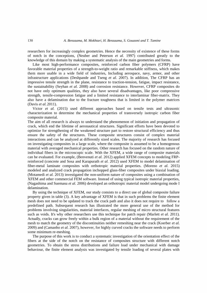
Advances in Aircraft and Spacecraft Science, Vol. 5, No. 1 (2018) 129-139 DOI: https://doi.org/10.12989/aas.2018.5.1.129 129
Copyright © 2018 Techno-Press, Ltd. http://www.techno-press.org/?journal=aas&subpage=7 ISSN: 2287-528X (Print), 2287-5271 (Online)
Using XFEM technique to predict the damage of unidirectional CFRP composite notched under tensile load
A. Benzaama1, M. Mokhtari2, H. Benzaama3, S. Gouasmi4 and
T. Tamine1
1Département de Génie Maritime, Université des Sciences et de la Technologie d’Oran USTOMB, Algeria 2Laboratoire de Recherche en Technologie de Fabrication Mécanique, Ecole Nationale Polytechnique,
ENP Oran M.A. Algeria 3Laboratory of applied Biomechanics and Biomaterials, Ecole Nationale Polytechnique, ENP Oran M.A.
Algeria 4Laboratoire de Mécanique de Structure et des Solides (LMSS), University of Sidi Bel Abbes, Algeria
(Received April 30, 2017, Revised September 13, 2017, Accepted September 15, 2017)
Abstract. The composite materials are widely used in aircraft structures. Their relative rigidity/weight
gives them an important advantage over the metal structures. The objective of this work is to analyze by the
finite element method the mechanical behavior of composite plate type notched with various forms under
tensile load. Two basic parameters were taken into consideration. The first, the form of the notch in order to
see its effect on the stress and the failure load. The second, we studied the influence of the locale orientation
of fiber around the plate’s notch. These parameters are studied in order to see their effects on the distribution
stress and failure load of the plate. The calculation of the failure load is determined numerically with the
numerical code ABAQUS using the XFEM (extended Finite Element Modeling) based on the fracture
mechanics. The result shows clearly that it is important to optimize the effect of fiber orientation around the
notch.
Keywords: CFRP (reinforced carbon fiber polymers); XFEM (extended finite element modeling)
1. Introduction
Several mechanism of damage can occur in composite structures, such as delamination of the
fiber-matrix interface, delamination of the interlayer’s in the case of the laminates and or else
breakage of the fibers. These mechanisms can occur simultaneously due to the effect of several
parameters such as the type of loading and the boundary conditions. The necessary presence of
some form of the notch in the structures causes an imbalance of resistance near the notch. Several
researchers have been interested in this research axis in order to characterize this phenomenon.
(Kirsh et al. 1898) was the first to study the phenomenon of stress concentration and distribution
around a hole. Subsequently, Analytical solutions have been gradually found by various
Corresponding author, E-mail: [email protected]
A. Benzaama, M. Mokhtari, H. Benzaama, S. Gouasmi and T. Tamine
researchers for increasingly complex geometries. Hence the necessity of existence of these forms
of notch in the conceptions, (Neuber and Peterson et al. 1997) contributed greatly to the
knowledge of this domain by making a systematic analysis of the main geometries and forms.
Like most high-performance composites, reinforced carbon fiber polymers (CFRP) have
favorable material properties of a strength-to-weight ratio and remarkable stiffness, which makes
them more usable in a wide field of industries, Including aerospace, navy, armor, and other
infrastructure applications (Deshpande and Tseng et al. 2007). In addition, The CFRP has an
impressive tensile strength in the plane, resistance to traction-tension, fatigue, impact resistance,
the sustainability (Seyhan et al. 2008) and corrosion resistance. However, CFRP composites do
not have only optimum qualities, they also have several disadvantages, like poor compressive
strength, tensile-compression fatigue and a limited resistance to interlaminar fiber-matrix. They
also have a delamination due to the fracture toughness that is limited in the polymer matrices
(Davis et al. 2011).
Victor et al. (2015) used different approaches based on tensile tests and ultrasonic
characterization to determine the mechanical properties of transversely isotropic carbon fiber
composite material.
The aim of all research is always to understand the phenomenon of initiation and propagation of
crack, which end the lifetime of aeronautical structures. Significant efforts have been devoted to
optimize for strengthening of the weakened structure part to restore structural efficiency and thus
ensure the safety of the structures. These composite structures consist of complex material
interactions and can be analyzed at differently sized scales. The majority of research has focused
on investigating composites in a large scale, where the composite is assumed to be a homogenous
material with averaged mechanical properties. Other research has focused on the random nature of
individual fibers in the microscopic scale. With the XFEM, a wide range of composite materials
can be evaluated. For example, (Benvenuti et al. 2012) applied XFEM concepts to modeling FRP-
reinforced (concrete and Sosa and Karapurath et al. 2012) used XFEM to model delamination of
fiber-metal laminate composites with orthotropic material properties. (Moreno et al. 2015)
modeled and analyzed crack propagation inchopped glass-fiber composites under biaxial loading.
(Motamedi et al. 2013) investigated the non-uniform nature of composites using a combination of
XFEM and other commercial FEM software. Instead of using typical isotropic material properties,
(Nagashima and Suemasu et al. 2006) developed an orthotropic material model undergoing mode I
delamination.
By using the technique of XFEM, our study consists to a direct use of global composite failure
property given in table (3). A key advantage of XFEM is that in such problems the finite element
mesh does not need to be updated to track the crack path and also it does not require to follow a
predefined path. Subsequent research has illustrated the more general use of the method for
problems involving singularities, material interfaces, regular meshing of micro structural features
such as voids. It's why other researchers use this technique for patch repair (Marlett et al. 2011).
Actually, cracks can grow freely within a bulk region of a material without the requirement of the
mesh to match the geometry of the discontinuities neither remeshing near the crack (Koerber et al.
2009) and (Camanho et al. 2007), however, for highly curved cracks the software needs to perform
some minimum re-meshing.
The purpose of this work is to conduct a systematic investigation of the orientation effect of the
fibers at the side of the notch on the resistance of composites structure with different notch
geometries. To obtain the stress distributions and failure load under mechanical with damage
behaviour, the finite element analysis was investigated by tensile loading of several plates with
130

Using XFEM technique to predict the damage of unidirectional CFRP composite...
notches of various forms and varied dimensions.
2. XFEM technique
The X-FEM uses the concept of partition of finite element unity and enrichment function. The
enrichment functions are expressed as follows (Moes et al. 1999)
𝑈𝑥𝑓𝑒𝑚(𝑋) = ∑ 𝑁𝑖(𝑋)𝑢𝑖
𝑖∈𝛤
+ ∑ 𝑁𝑖(𝑋)𝐻(𝑋)𝑎𝑖
𝑖∈𝐽
+ ∑[𝑁𝑖(𝑋) ∑ 𝐹𝛼(𝑋)𝑏𝑖𝛼
4
𝛼=1
𝑖∈𝐾
] (1)
Where (Γ) is the set of all nodes in the mesh, (Ni (X)) is the nodal shape function and (ui) is the
standard (degree of freedom) DOF of node (i) (ui represents the physical nodal displacement for
non-enriched nodes only). The subsets (J) and (K) contain the nodes enriched with Heaviside
Function (H (X)) or crack-tip function (Fα(X)), respectively, and (ai, biα) are the corresponding
DOFs. The first and second term on the right-hand side is applicable to all nodes in the model; the
third term is valid for nodes whose shape function support is cut by the crack interior and the third
term is used only for nodes whose shape function support is cut by the crack tip (Qian et al. 2012).
Fig. 1 Description of the E1EJEK sets of the displacement field approximation enriched finite element
The Heaviside function (H (X)) is defined as follow
H (x) = { −1, 𝑖𝑓 𝑥 > 0 1, 𝑖𝑓 𝑥 < 0
(2)
The crack-tip function (Fα(X)) contains the enrichment functions (branch functions) used to
increase the accuracy of the numerical solution around crack tip and their formulation depends on
the nature of the problem to be solved. For LEFM problems, these functions are chosen based on
the asymptotic behavior of the displacement field at the crack tip (Belytschko et al. 1999)
𝐹𝛼(𝑋) = [√𝑟 sin𝜃
2 , √𝑟 cos
𝜃
2, √𝑟 sinθ sin
𝜃
2 , √𝑟 sin 𝜃 cos
𝜃
2 (3)
Where (θ, r) are a polar coordinates system with its origin at the crack tip and when (θ = 0) it is
tangent to the crack at the tip, √r sin(θ/2 takes into account the discontinuity across the crack face.
This function has a lot of applications including biomaterial and elastic-plastic power law
131
A. Benzaama, M. Mokhtari, H. Benzaama, S. Gouasmi and T. Tamine
hardening material.
3. XFEM input parameter
The plate domain is created as a solid part of the solid section, The X-FEM enrichment domain
function is input as follows:
*Enrichment, name=Crack-1, type=PROPAGATION CRACK, activate= ON
The solid composites section is used for the X-FEM domain, whereas the thickness section is
created as one single solid composites section. Therefore, this domain section serves the X-FEM
purpose. The evaluated damage is maximal at crack opening and is calculated using the following
equation (ABAQUS 2009)
(GI
CIC) + (
GII
GIIC) + (
GIII
GIIIC) =1 (4)
The following analysis uses the elastic properties of Carbon fiber reinforced polymer that are
listed in Table 2. The maximum principal stress is the value of the un-notched nominal strength
which is measured as (2560) MPa in first direction and 64 MPa in the second direction. In
addition, the damage evaluation criterion is maximum traction energy (maximum crack opening of
the composite specimen is experimentally measured as 81.5, 106.3, 106.3). Therefore, the input
file of the order line in the software becomes as follow:
*Damage Initiation, criterion=MAXS 2560. 2560. 500.
*Damage Evolution, type=ENERGY 81.5, 0.277, 0.277
*Damage Stabilization 1e-5
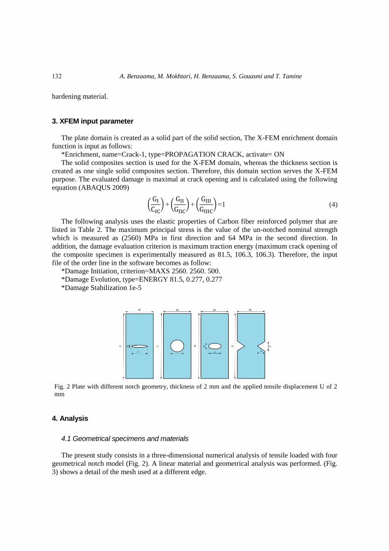
Fig. 2 Plate with different notch geometry, thickness of 2 mm and the applied tensile displacement U of 2
mm
4. Analysis
4.1 Geometrical specimens and materials
The present study consists in a three-dimensional numerical analysis of tensile loaded with four
geometrical notch model (Fig. 2). A linear material and geometrical analysis was performed. (Fig.
3) shows a detail of the mesh used at a different edge.
132
Using XFEM technique to predict the damage of unidirectional CFRP composite...
In tensile behavior the restraining and loading condition consists on applying a restraint in the
edge and tensile displacement at the opposite edge.
Table 1 Dimension of different notch geometry
B(elliptical) e(circular) c(elliptical) f (V lateral)
H = 140 mm H = 140 mm H = 140 mm H = 140 mm
W= 50 mm W = 50 mm W = 50 mm W = 50 mm
a = 20 mm D = 20 mm a = 20 mm a = 20 mm
b = 1/4 a b = 20 mm b = 1/2a b = a
The mesh subjectivity of the proposed model is illustrated by simulating the response of a
notched GFRP composite which is loaded in tension. The simulated specimen has 2 mm in
thickness, 140 mm in length and 50 mm in width. Its contains in the first case, different dimension
of a central notch. In the second, it has three modification of fiber orientation. On the other hand,
Table 3 lists the used properties. The meshes were constructed with bias effects and swept
technique using (C3D8R) element type, to generate dense mesh in region around the notch in order
to capture the peak stresses which practical presented concentration stress and initiation of crack
grow, whereas coarser structure meshing is used for the other domain region, to reduce the
calculations time. The section through thickness is simulated using only one dependent section to
help node set convergence.
Table 2 Elastic, strength and fracture properties of the composite used
Longitudinal Young’s modulus 𝐸1 (GPa) 162
Transverse Young’s modulus 𝐸2 (GPa) 8.96
Poisson’s ratio 𝑣12 0.316
Shear modulus 𝐺12 (GPa) 4.69
Shear modulus 𝐺13 (GPa) 4.69
Shear modulus 𝐺23 (GPa) 3.973
Longitudinal tensile strength 𝑋𝑇 (MPa) 2560
Transverse tensile strength 𝑌𝑇(MPa) 64
Longitudinal fracture energy GI (kJ/m2) 81.5
Transverse fracture energy GII=GIII(J/m2) 277
As shown in the following figure, several local marks were surrounded by the different types of
notches to guide the orientation of the fibers according to the shape of the notch. The area away
from this notch was attached only by a single mark oriented in the direction of loading
(unidirectional composite). We use Assigning Material Orientation. This technique can be done
either by “Create Geometric Part” or by “Create Mesh Part” in order to sweep the structure by
local marks that indicate the orientation of the fibers.
133
A. Benzaama, M. Mokhtari, H. Benzaama, S. Gouasmi and T. Tamine
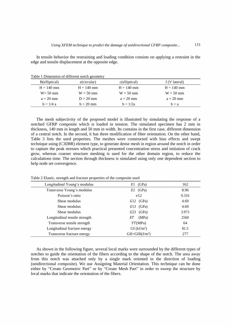
Fig. 3 Detail of the mesh of different geometrical notch
Fig. 4 Schematizations of the local marks for the modification 3 of the circular notch shap
Fig. 5 XFEM load displacement curve of (a) circular, (b) elliptical of a/b=2 and (c) elliptical of a/b=4 and (d)
lateral V, for different deferent notch size
The presence of the notch in the structures weakens its resistance. This leads to a concentration
of stresses leading to the formation of a crack. The solution of this problem can be done by a
geometric reinforcement.
134

Using XFEM technique to predict the damage of unidirectional CFRP composite...
4.2 Effect of the size of different geometrical notch type on the damage of the plate
The Objective oriented in this section it’s to canceled the property effect then to keep the same
rapport (W/ H, a/ W). Another objective is to intervener only on the effect of the size of each notch
form upon the predicted the failure that occur in the plate configurations. Thus, it can be
demonstrated the robustness of this type of analysis.
The desired magnitude to be evaluated in these curves is the resistance of the plates to the
damage represented by the load-displacement curves. The overall response during the loading of
the plates to the damage is ensured by the reaction of the force at the level of the embedment and
the displacement at the level of the surface where applies the load. This is to illustrate the overall
response of our notched plate.
In the figure, it is clear that there is a proportionality between the dimensioning of the notch
and the damage force in an order of value of 10 KN in average between each dimension of the
notch. It is also evident that the values are also proportional to the rupture parameter of the
damaged composite. These values do not exceed 160 KN. Depending on the shape of the notch, it
is found that the plates with a small notch are more resistant than those with a large notch. This
can be reflected in the fact that the plate with an oversized notch will extend even further, resulting
in a decrease in the damage force. So, the longer the plate has an ability to lie, the less resistant it
is.
The same applies to other forms of notches with different values except for the V-shaped notch
which presents itself with high values and the same pitch between these different dimensions. This
is due to their positioning which makes them more resistant (edge effect), despite the fact that this
sharp shape favors the initiation and rapid propagation of the crack.
Fig. 6 Stress distribution of each form of notch under (a) modifcation1 and (b) modification 2 (c)
modification3
4.3 Effect of the modification of the fiber orientation on damage of plate
Let us start from the idea that these modifications move a part of the concentration zone of the
stresses towards the zones of discontinuity of the fibers.
In this section, the effects of the fiber orientation (d/b ratio) on the ultimate failure load of a
unidirectional composite plate with an elliptical, circular and lateral v notch are shown in Fig. 4.
135
A. Benzaama, M. Mokhtari, H. Benzaama, S. Gouasmi and T. Tamine
XFEM failure criterion is used to predict the ultimate failure load in this analysis. Fig. 3 indicates
that the ultimate load decreases when the cutout size increases i.e., d/b ratio increases the reduction
in ultimate failure load is 26%, 42% and 54%, respectively.
From the Fig. 3, it is also observed that, reduction rate in ultimate failure load decreases, as the
cutout size increases.
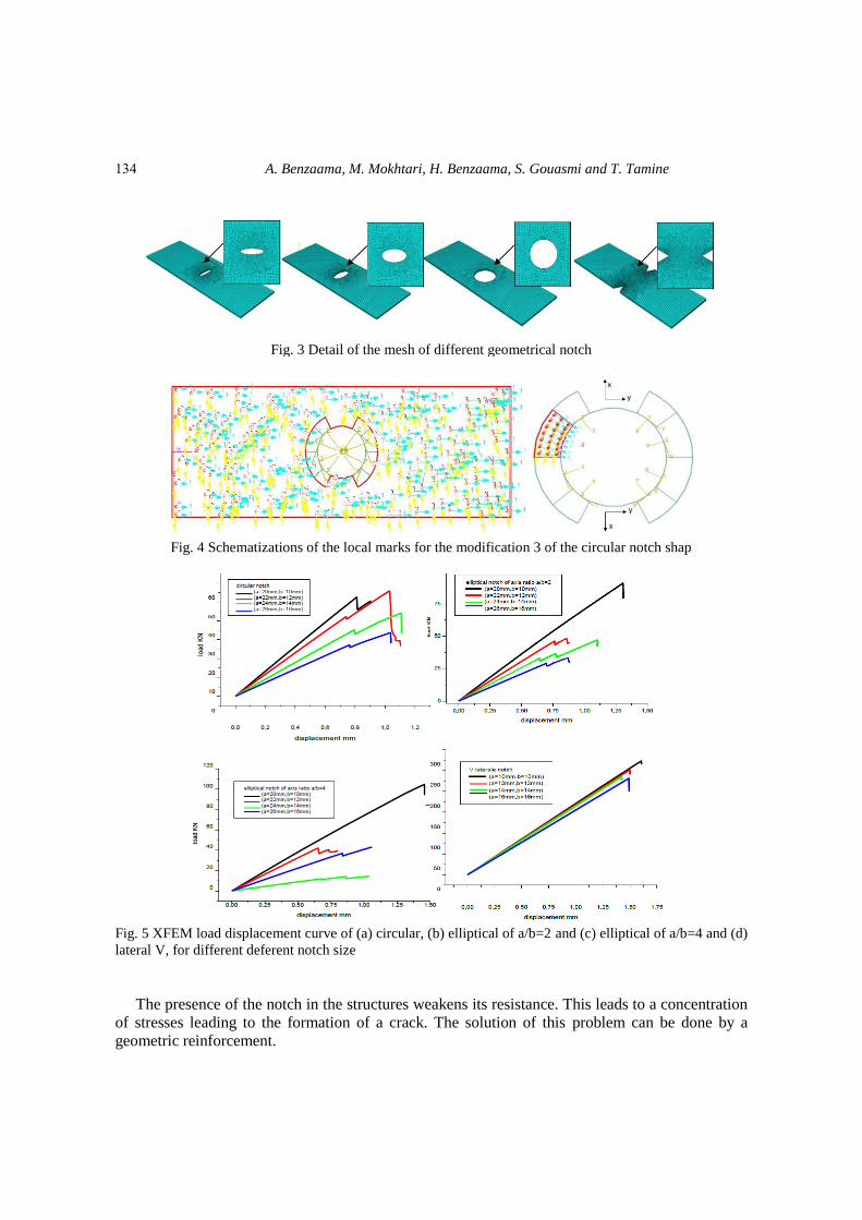
Fig. 7 The fiber orientation form of composite around the notch
The effect of fiber orientation of each plate under tensile strength is investigated by changing
its orientation around the notch. The notch size is held constant at the baseline values, also the
property of CFRP. The variation of tensile strength of the plate with different form of notch is
shown in Fig. 6.
We have limited ourselves only to the presentation of the circular shape of the notch. The other
geometric shapes follow these same three types of modification. The only problem posed in these
modifications is the discontinuity of the fibers, which are well illustrated in these schematizations
and these zones of concentration of the stresses.
-For the first modification, the notch must be tried symmetrically and in the transverse zone of
the surrounded plate notch by the fibers.
-For the second modification, the notch may be symmetrically surrounded along the diagonal of
the plate.
-For the third modification, the fibers are vertical at the notch along the longitudinal zone of the
plate. These three modifications made appear fibers that are not continued in the notched plates.
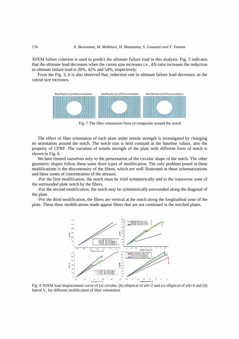
Fig. 8 XFEM load displacement curve of (a) circular, (b) elliptical of a/b=2 and (c) elliptical of a/b=4 and (d)
lateral V, for different modification of fiber orientation
136
Using XFEM technique to predict the damage of unidirectional CFRP composite...
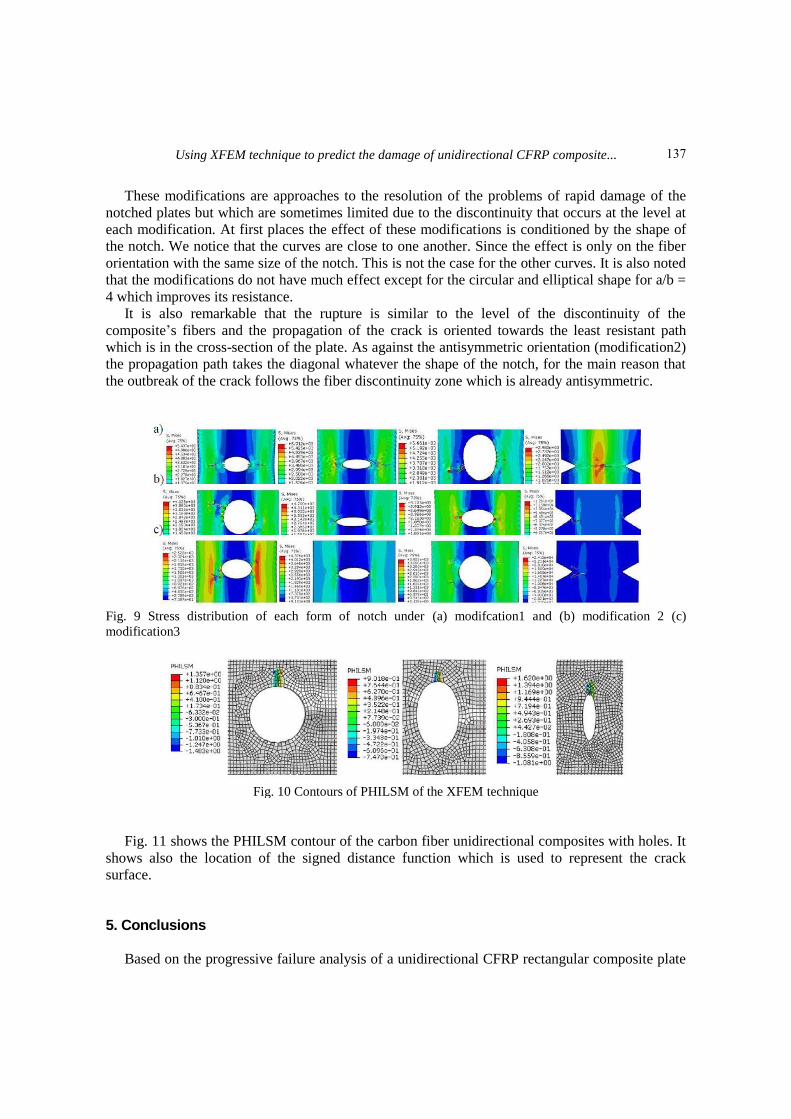
These modifications are approaches to the resolution of the problems of rapid damage of the
notched plates but which are sometimes limited due to the discontinuity that occurs at the level at
each modification. At first places the effect of these modifications is conditioned by the shape of
the notch. We notice that the curves are close to one another. Since the effect is only on the fiber
orientation with the same size of the notch. This is not the case for the other curves. It is also noted
that the modifications do not have much effect except for the circular and elliptical shape for a/b =
4 which improves its resistance.
It is also remarkable that the rupture is similar to the level of the discontinuity of the
composite’s fibers and the propagation of the crack is oriented towards the least resistant path
which is in the cross-section of the plate. As against the antisymmetric orientation (modification2)
the propagation path takes the diagonal whatever the shape of the notch, for the main reason that
the outbreak of the crack follows the fiber discontinuity zone which is already antisymmetric.
Fig. 9 Stress distribution of each form of notch under (a) modifcation1 and (b) modification 2 (c)
modification3
Fig. 10 Contours of PHILSM of the XFEM technique
Fig. 11 shows the PHILSM contour of the carbon fiber unidirectional composites with holes. It
shows also the location of the signed distance function which is used to represent the crack
surface.
5. Conclusions
Based on the progressive failure analysis of a unidirectional CFRP rectangular composite plate
137

A. Benzaama, M. Mokhtari, H. Benzaama, S. Gouasmi and T. Tamine
with a central elliptical, circular and lateral V of notch cutout under uniform uniaxial tensile
loading, the following conclusions are drawn:
- XFEM is demonstrated to be a very capable technique to predict the fracture action during the
crack propagation to failure of unidirectional CFRP composite.
- The presence of the notch weakens the structure and causes a reduction in the stiffness of the
structure.
- The rigidity of the plate is disturbed by the presence of a geometrical defect; the reduction in
rigidity varies with the shape and the dimension of the notch.
- The stress concentration increases with the shape and size of the notch and can be reduced by
the presence of an introduced fiber orientation change.
- For a rectangular unidirectional CFRP composite plate with a central elliptical, circular and
lateral V notch, ultimate failure loads magnitudes are decreased by increasing the size of notch.
- Ultimate failure loads magnitudes can be increased despite the discontinuity of unidirectional
fiber and this by the appropriate between the type of modification and shape of the notch, case of
circular and elliptical notch.
- The position of the notch in the uniaxial load structure influences on the value of failure load,
the case of the V-shaped lateral notch, so the notch at the side of the plate if it does not exceed its
critical size is less dangerous to that of the central notch.
- The birth of crack and its propagation depends directly on the orientation of the fibers at the
tip of the notch.
References ABAQUS, Abaqus Version (2009), 6.9 Documentation, Providence, RI: DassaultSystemesSimulia
Corporation.
Belytschko, T. and Black, T. (1999), “Elastic crack growth in finite elements with minimal remeshing”, J.
Numer. Meth. Eng., 45(5), 601-620. Benvenuti, E., Vitarelli, O. and Tralli, A. (2012), “Delamination of FRP-reinforced concrete by means of an
extended finite element formulation”, Compos. Part B: Eng., 43(8), 3258-3269.
Camanho, P.P., Maimí, P. and Dávila, C.G. (2007), “Prediction of size effects in notched laminates using
continuum damage mechanics”, Compos. Sci. Technol., 67, 2715-2727.
Curiel Sosa, J.L. and Karapurath, N. (2012), “Delamination modelling of GLARE using the extended finite
element method”, Compos. Sci. Technol.
Davis, D.C. and Whelan, B.D. (2011), “An experimental study of interlaminar shear fracture toughness of a
nanotube reinforced composite”, Compos. B Eng., 42, 105-116.
Koerber, H. and Camanho, P.P. (2009), “Characterisation of unidirectional carbon epoxy IM7-8552 in
longitudinal compression under high strain rates”, Proceedings of the 3rd International Conference on
Integrity, Reliab. Fail.
Marlett, K. (2011), Hexcel 8552 IM7 Unidirectional Prepreg 190 gsm & 35% RC Qualification Material
Property Data Report.
Moes, N., Dolbow, J. and Belytschko T. (1999), “A finite element method for crack growth without
remeshing”, J. Numer. Meth. Eng., 46(1), 132-150. Moreno, M.C.S., Curiel-Sosa, J.L., Navarro-Zafra, J., Martinez Vicente, J.L. and López Cela, J.J. (2015),
“Crack propagation in a chopped glass-reinforced composite under biaxial testing by means of XFEM”,
Compos. Struct., 119, 264-271.
Motamedi, D. (2013), “Nonlinear XFEM modeling of delamination in fiber reinforced composites
138

Using XFEM technique to predict the damage of unidirectional CFRP composite...
considering uncertain fracture properties and effect of fiber bridging”, Ph.D. Dissertation, University of
British Columbia, Canada.
Nagashima, T. and Suemasu, H. (2006), “Stress analyses of composite laminate with delamination using
XFEM”, J. Comput. Meth., 3(4), 521. Neuber, H. (1961), “Theory of stress concentration for shear strained prismatic bodies with nonlinear stress-
strain law”, J. Appl. Mech., 28(4), 544-550.
Pilkey, W. and Peterson’s, D. (1997), Stress Concentration Factors, Wiley, New York, U.S.A.
Qian, Z.D. and Jing, H. (2012), “Fracture properties of epoxy asphalt mixture based on extended finite
element method”, J. Centr. South Univ., 19(11), 3335.
Seyhan, A.T. Tanoglu, M. and Schulte, K. (2008), “Mode I and mode II fracture toughness of e-glass non-
crimp fabric/carbon nanotube (CNT) modified polymer based composites”, Eng. Fract. Mech., 75, 5151-
5162.
Tan, J.L.Y., Deshpande, V.S. and Fleck, N.A. Prediction of Failure in Notched CFRP Laminates Under
Multi-Axial Loading, Cambridge University Engineering Dept., Trumpington St., Cambridge, CB2 1PZ,
U.K.
Tseng, C.H., Wang, C.C. and Chen, C.Y. (2007), “Functionalizing carbon nanotubes by plasma modification
for the preparation of covalent-integrated epoxy composites”, Chem. Mater., 19, 308-315.
Victor, M., Marianne, P., Marie-Laetitia, P., Helene, W., Arthur, C. and Moussa, K. (2015),
“Determination of the elastic properties in CFRP composites: Comparison of different approaches based
on tensile tests and ultrasonic characterization”, Adv. Aircr. Spacecr. Sci., 2(3), 249.
CC
139