Embed Size (px)
Citation preview
Treball Final de Grau
Tutor/s
Dr. Esther Chamarro Aguilera Department of Chemical Engineering
Dr. Manel Vicente Buil Department of Chemical Engineering
Study of a biodiesel batch production from degummed soybean oil.
Estudio de la producción de biodiesel en discontinuo a partir del aceite de soja desgomado.
Ainhoa Ortiz Peláez June 2017


Aquesta obra esta subjecta a la llicència de: Reconeixement–NoComercial-SenseObraDerivada
http://creativecommons.org/licenses/by-nc-nd/3.0/es/


“Una vez que aceptamos nuestros límites, podemos ir más allá de ellos.”
Albert Einstein
En primer lugar, agradecer a mis tutores, Dr. Manel Vicente y Dra. Esther Chamarro, por
toda su dedicación y apoyo durante estos largos y duros meses. Han sido, y serán, una
inspiración y un modelo a seguir.
Por otro lado, agradecer a mi familia y amigos todo el apoyo recibido en los momentos de
estrés y ofuscación.

CONTENTS
SUMMARY i
RESUM iii
1. INTRODUCTION 1
1.1. Biodiesel production by soybean oil 2
1.1.1. Transesterification reaction 4
2. OBJECTIVES 5
3. BASIC DESIGN 7
3.1. Block diagram 8
3.2. Design bases 11
3.3. Reaction 11
3.4. Settler 12
3.5. Recipie 13
3.6. Process flow diagram 14
4. PROJECT SPECIFICATIONS 19
4.1. Vessels V-01 and V-02 19
4.1.1. Auxiliary equipments 20
4.1.2. Operating conditions 21
4.2. Settlers S-01 and S-02 23
4.3. Heat exchanger 24
4.4. Valves & Pipes 26
4.5. Pumps 27
8 Ortiz Peláez, Ainhoa
4.6. Plant Services 28
4.7. Storage tanks 29
5. P&ID 31
6. EQUIPMENT LIST 37
7. SCHEDULING 39
7.1. General considerations 39
7.2. Batch time 41
73. Production capacity 43
7.3.1. Production in non-overlapping campaign 43
7.3.2. Production in overlapping campaign 44
7.4. Highest capacity 47
7.5. Determination of operation strategy 48
7.5.1. Working in one campaign 49
7.5.2. Working in two campaigns 51
8. CONCLUSIONS 55
REFERENCES AND NOTES 57
ACRONYMS 59
TABLE AND FIGURES LISTS AND DIAGRAMS 63
APPENDICES 67
APPENDIX 1: SAFETY DATA SHEETS 69
APPENDIX 2: CALCULATION MANUAL 75
APPENDIX 3: SPECIFICATION SHEETS 87
Study of a biodiesel batch production from degummed soybean oil i
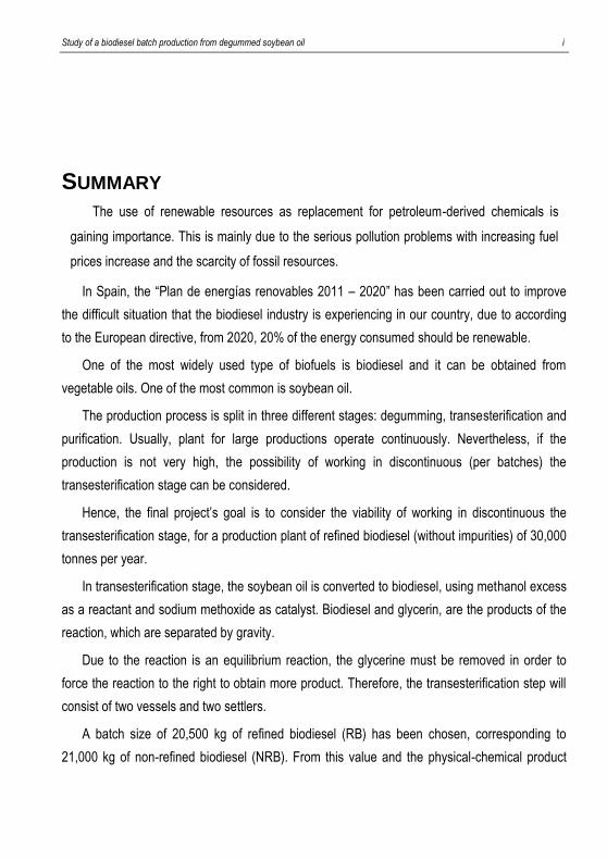
SUMMARY
The use of renewable resources as replacement for petroleum-derived chemicals is
gaining importance. This is mainly due to the serious pollution problems with increasing fuel
prices increase and the scarcity of fossil resources.
In Spain, the “Plan de energías renovables 2011 – 2020” has been carried out to improve
the difficult situation that the biodiesel industry is experiencing in our country, due to according
to the European directive, from 2020, 20% of the energy consumed should be renewable.
One of the most widely used type of biofuels is biodiesel and it can be obtained from
vegetable oils. One of the most common is soybean oil.
The production process is split in three different stages: degumming, transesterification and
purification. Usually, plant for large productions operate continuously. Nevertheless, if the
production is not very high, the possibility of working in discontinuous (per batches) the
transesterification stage can be considered.
Hence, the final project’s goal is to consider the viability of working in discontinuous the
transesterification stage, for a production plant of refined biodiesel (without impurities) of 30,000
tonnes per year.
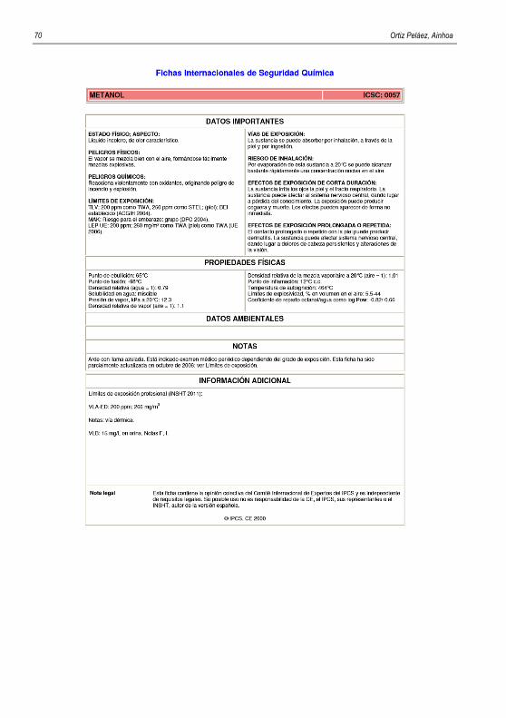
In transesterification stage, the soybean oil is converted to biodiesel, using methanol excess
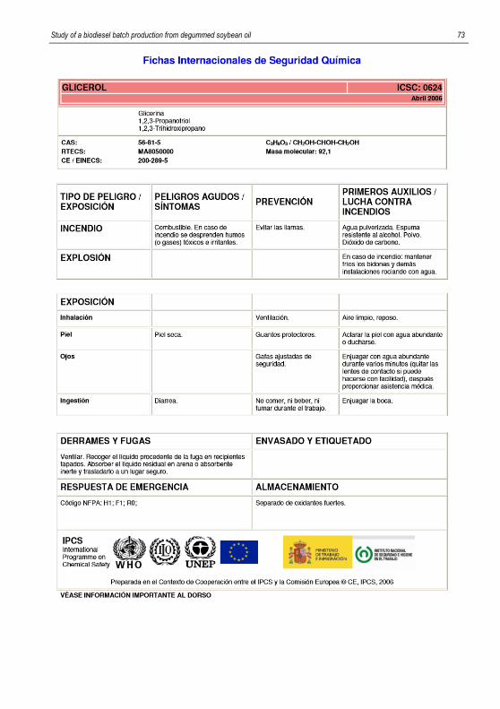
as a reactant and sodium methoxide as catalyst. Biodiesel and glycerin, are the products of the
reaction, which are separated by gravity.
Due to the reaction is an equilibrium reaction, the glycerine must be removed in order to
force the reaction to the right to obtain more product. Therefore, the transesterification step will
consist of two vessels and two settlers.
A batch size of 20,500 kg of refined biodiesel (RB) has been chosen, corresponding to
21,000 kg of non-refined biodiesel (NRB). From this value and the physical-chemical product
ii Ortiz Peláez, Ainhoa
properties have been dimensioned the main equipment. Also, the block and process diagrams
have been made with their corresponding mass balance.
The necessary pumps, valves and pipes have been chosen, as well as the automation and
control system that is presented in the corresponding in the P&ID. Block and process diagram
and P&ID have been drawn with AutoCad.
Moreover, it has been estimated the times of each equipment that it should be carried out,
as well as, the period of occupation of the equipment. Working in two campaigns with
overlapping, batch time and cycle time have been determined. In this case, the batch time is 7.5
(BT = 7.5 h) and the cycle time is 3 hours (CT = 3h).
Different scheduling strategies of the transesterification batch production have been
proposed.
The most convenient has been the weekly production of 31 or 32 batches, in two campaigns
of 15 and 16 batches, the first one, and 15 and 17 batches, the second one. In addition, even if
the purification stage and the recovery methanol excess operates continuously without
disruption, the transesterification stage will work only 5 days per week, with 3 shifts per day,
without working the weekends.
Working with two campaigns per week, necessarily involves an intermediate shutdown,
which it will be used for cleaning work and maintenance. Moreover, this shutdown has been
programmed in such a way that it takes place coinciding with the central shift of the plant.
Keywords: refined biodiesel, non-refined biodiesel, transesterification, batch production, basic
design.
Study of a biodiesel batch production from degummed soybean oil iii
RESUMEN
El uso de recursos renovables como reemplazo de productos químicos derivados del
petróleo está ganando importancia, debido a los graves problemas de contaminación junto con
el aumento de los precios de los combustibles y la escasez de recursos fósiles.
En España se ha llevado a cabo el plan de energías renovables 2011 – 2020 para mejorar
la difícil situación que atraviesa la industria del biodiesel en nuestro país, ya que, según la
directiva europea, a partir del 2020 el 20% de la energía consumida, ha de ser renovable.
Uno de los biocombustibles más utilizados es el biodiesel, y puede ser obtenido de diversos
aceites vegetales. Uno de los más comunes es el aceite de soja.
El proceso de obtención del biodiesel a partir del aceite de soja consta de tres etapas:
desgomado, transesterificación y purificación. Normalmente, las plantas para grandes
producciones operan en continuo. Sin embargo, si la producción no es muy elevada, se puede
considerar la posibilidad de trabajar en discontinuo (por lotes) la etapa de transesterificación.
Así pues, el objetivo final de este proyecto es, para una planta de producción de biodiesel
refinado (sin impurezas) de 30.000 toneladas al año, plantear la viabilidad de trabajar la etapa
en discontinuo de transesterificación.
En la etapa de transesterificación, el aceite de soja se convierte en biodiesel, utilizando
metanol en exceso como reactivo y metóxido sódico como catalizador. El biodiesel y la
glicerina, son los productos de la reacción, que se separarán por gravedad.
Puesto que la reacción, es una reacción de equilibrio, se retirarán la glicerina para poder
producir más biodiesel. Por lo tanto, el proceso de transesterificación constará de dos reactores
y dos decantadores.
Se ha elegido un tamaño de batch de 20,5 kg de biodiesel por batch, que corresponde a
21,0 t de biodiesel no refinado (NRB). A partir de este valor y de las propiedades físico-
químicas de los productos se han dimensionado los equipos principales. Asimismo, se han
realizado los diagramas de bloques y de proceso con su correspondiente balance de materias.
iv Ortiz Peláez, Ainhoa
Se han elegido las bombas, válvulas y las tuberías necesarias, así como el sistema de
automatización y control que se presenta en el diagrama P&ID correspondiente. Los diagramas
de bloques y de proceso y el P&ID, se han elaborado con AutoCad.
Por otra parte, se han estimado los tiempos de cada una de las tareas que se deben llevar
a cabo y los tiempos de ocupación de los equipos involucrados, determinándose el batch time y
el cycle time, si se produce secuencialmente en campañas con solapamiento. En este caso,
han resultado ser el batch time de 7,5 h (BT = 7,5), y el cycle time de 3 h (CT = 3 h).
Se han planteado distintas formas de programación de la producción en discontinuo de la
etapa de transesterificación, resultando la más conveniente la producción semanal de 31 o 32
lotes, en dos campañas de 15 y 16 lotes y de 15 y 17 lotes respectivamente. Además, aunque
la etapa de purificación y recuperación del metanol funcione en continuo sin interrupción, la
etapa de transesterificación trabajará únicamente 5 días a la semana a tres turnos por día, no
siendo necesario trabajar los fines de semana.
El trabajar con dos campañas por semana, comporta necesariamente una parada
intermedia, que se utilizará para trabajos de limpieza y mantenimiento. Asimismo, está parada
se ha programado de tal forma que se lleve a cabo coincidiendo con el turno central de la
planta.
Palabras claves: Biodiesel refinado, biodiesel no refinado, transesterificación, producción en
discontinuo, diseño básico.
Study of a biodiesel batch production from degummed soybean oil 1
1. INTRODUCTION
During the last century, the fossils fuels (coal, oil and natural gas) have been be the worlds
primary energy source. However, the use of non-renewable fuels has been being reckless. Fuel
gases, emissions from refineries and factories, etc., together with exhaust emission from
vehicles are the leading sources of air pollution. It is necessary to begin using to renewable
energy sources to avoid massive economic disruption caused by a global energy crisis. (1)
Any hydrocarbon fuel that is produced from organic material in a short period of time is
considered a biofuel. Although, biofuels can also be made through chemical reactions carried
out in a laboratory or industrial setting, that use organic matter (biomass) to make fuel. The only
real requirements for a biofuel are firstly that the starting material must be CO2, was fixed by a
living organism and the final fuel product must be produced relatively quickly and not over
millions of years. (2)
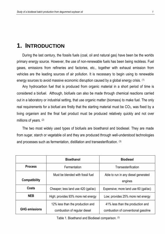
The two most widely used types of biofuels are bioethanol and biodiesel. They are made
from sugar, starch or vegetable oil and they are produced through well-understood technologies
and processes such as fermentation, distillation and transesterification. (3)
Bioethanol Biodiesel
Process Fermentation Transesterification
Compatibility
Must be blended with fossil fuel Able to run in any diesel generated
engines
Costs Cheaper; less land use 420 (gal/ac) Expensive; more land use 60 (gal/ac)
NEB High; provides 93% more net energy Low; provides 25% more net energy
GHG emissions
12% less than the production and
combustion of regular diesel
41% less than the production and
combustion of conventional gasoline
Table 1. Bioethanol and Biodiesel comparison. (3)
2 Ortiz Peláez, Ainhoa
We can stage that the advantages of biodiesel manufacturing are better than bioethanol
manufacturing.
BIODIESEL PRODUCTION BY SOYBEAN OIL
Normally, the composition of soybean oil is composed primarily of triglycerides with different
free fatty acids (FFA). Nevertheless, the FFA of soybean oil are primarily unsaturated
(approximately 68.3%), like linoleic, linolenic and oleic acid. Palmitic acid and stearic acid are
saturated FFA. (4)
To simplify this model, it is assumed that there is only one kind of component acid or FFA,
oleic acid and therefore, one type of triglyceride, triolein. It is important to know the chief part of
FFA are triglycerides. Hereunder, the composition of soybean oil can be seen. (4)
Compound Weight fraction
Triolein 0.975
Oleic acid 1.910·10-2
Water 6.030·10-3
PE-Ca 1.670·10-4
Total 1.000
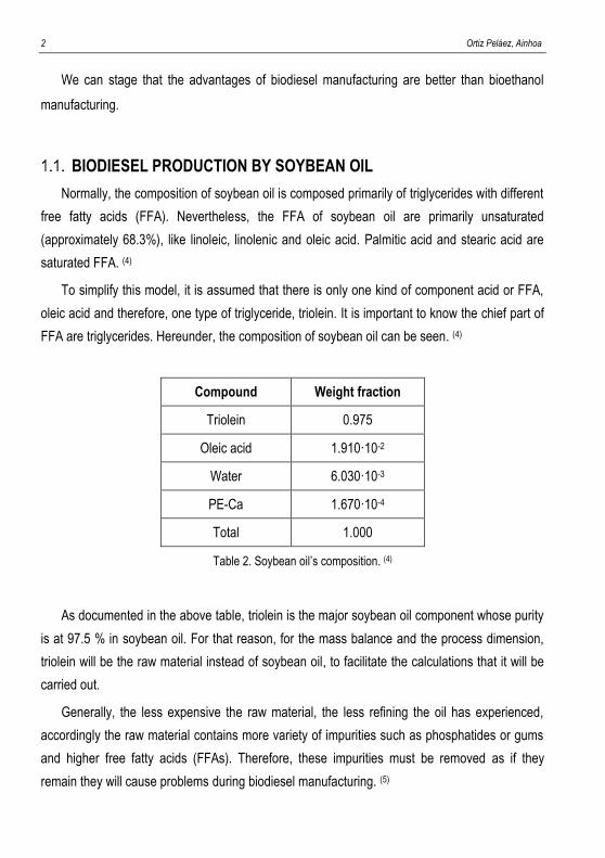
Table 2. Soybean oil’s composition. (4)
As documented in the above table, triolein is the major soybean oil component whose purity
is at 97.5 % in soybean oil. For that reason, for the mass balance and the process dimension,
triolein will be the raw material instead of soybean oil, to facilitate the calculations that it will be
carried out.
Generally, the less expensive the raw material, the less refining the oil has experienced,
accordingly the raw material contains more variety of impurities such as phosphatides or gums
and higher free fatty acids (FFAs). Therefore, these impurities must be removed as if they
remain they will cause problems during biodiesel manufacturing. (5)
Study of a biodiesel batch production from degummed soybean oil 3
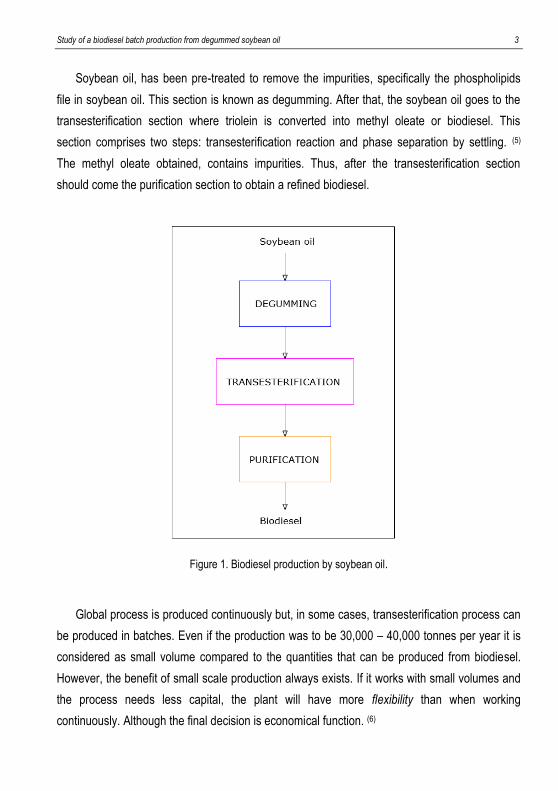
Soybean oil, has been pre-treated to remove the impurities, specifically the phospholipids
file in soybean oil. This section is known as degumming. After that, the soybean oil goes to the
transesterification section where triolein is converted into methyl oleate or biodiesel. This
section comprises two steps: transesterification reaction and phase separation by settling. (5)
The methyl oleate obtained, contains impurities. Thus, after the transesterification section
should come the purification section to obtain a refined biodiesel.
Figure 1. Biodiesel production by soybean oil.
Global process is produced continuously but, in some cases, transesterification process can
be produced in batches. Even if the production was to be 30,000 – 40,000 tonnes per year it is
considered as small volume compared to the quantities that can be produced from biodiesel.
However, the benefit of small scale production always exists. If it works with small volumes and
the process needs less capital, the plant will have more flexibility than when working
continuously. Although the final decision is economical function. (6)
4 Ortiz Peláez, Ainhoa
1.1.1. Transesterification reaction
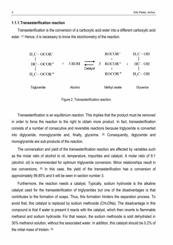
Transesterification is the conversion of a carboxylic acid ester into a different carboxylic acid
ester. (7) Hence, it is necessary to know the stoichiometry of the reaction.
Figure 2. Transesterification reaction.
Transesterification is an equilibrium reaction. This implies that the product must be removed
in order to force the reaction to the right to obtain more product. In fact, transesterification
consists of a number of consecutive and reversible reactions because triglyceride is converted
into diglyceride, monoglyceride and, finally, glycerine. (8) Consequently, diglyceride and
monoglyceride are sub-products of the reaction.
The conversation and yield of the transesterification reaction are affected by variables such
as the molar ratio of alcohol to oil, temperature, impurities and catalyst. A molar ratio of 6:1
(alcohol: oil) is recommended for optimum triglyceride conversion. Minor relationships result in
low conversions. (8) In this case, the yield of the transesterification has a conversion of
approximately 99.85% and it will be seen in section number 3.
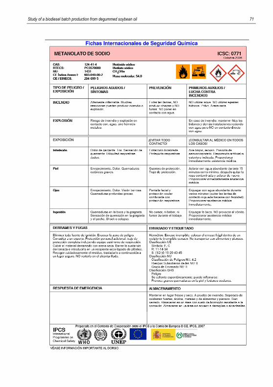
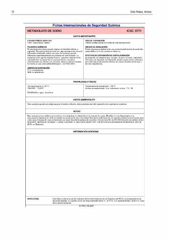
Furthermore, the reaction needs a catalyst. Typically, sodium hydroxide is the alkaline
catalyst used for the transesterification of triglycerides but one of the disadvantages is that
contributes to the formation of soaps. Thus, this formation hinders the separation process. To
avoid that, this catalyst is replaced by sodium methoxide (CH3ONa). The disadvantage in this
compound is that if water is present it reacts with the catalyst, which then reverts to flammable
methanol and sodium hydroxide. For that reason, the sodium methoxide is sold dehydrated in
30% methanol solution, without the associated water. In addition, this catalyst should be 0.2% of
the initial mass of triolein. (9)
Study of a biodiesel batch production from degummed soybean oil 5
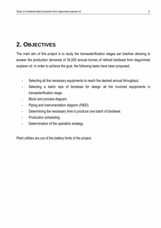
2. OBJECTIVES
The main aim of this project is to study the transesterification stages per batches allowing to
answer the production demands of 30,000 annual tonnes of refined biodiesel from degummed
soybean oil. In order to achieve the goal, the following tasks have been proposed:
- Selecting all the necessary equipments to reach the desired annual throughput.
- Selecting a batch size of biodiesel for design all the involved equipments in
transesterification stage.
- Block and process diagram.
- Piping and instrumentation diagram (P&ID).
- Determining the necessary time to produce one batch of biodiesel.
- Production scheduling.
- Determination of the operation strategy.
Plant utilities are out of the battery limits of the project.

6 Ortiz Peláez, Ainhoa
Study of a biodiesel batch production from degummed soybean oil 7
3. BASIC DESIGN
Biodiesel production has the following reagents: soybean oil and methanol, using sodium
methoxide as a catalyst, and the products are biodiesel, glycerine and waste. As it has been
commented in introduction section. Comment that in this project, the soybean oil will come
without phosphates, that is mean degummed soybean oil.
The three stages for obtaining biodiesel are produced in continuous, although the
transesterification stage is going to be studied by batches. Another important aspect is the
methanol’s recovery. The stoichiometry of the reaction shows that 3 methanol moles are
needed by one mole of soybean oil but for obtaining a better conversion, 6 methanol moles are
needed, this mean an excess of methanol. This excess must be recovered to minimize raw
material costs and, in consequence, increase the process benefits. Depending on how this
recovery is, the benefits will be higher or lower.
Hence, purification stage does not only imply the impurities elimination from biodiesel,
but also separates glycerine from biodiesel and it recovers the methanol excess. To be able to
treat methanol and to recover it, the bibliography shows that 15% of methanol is gone with
glycerine stream. (10)
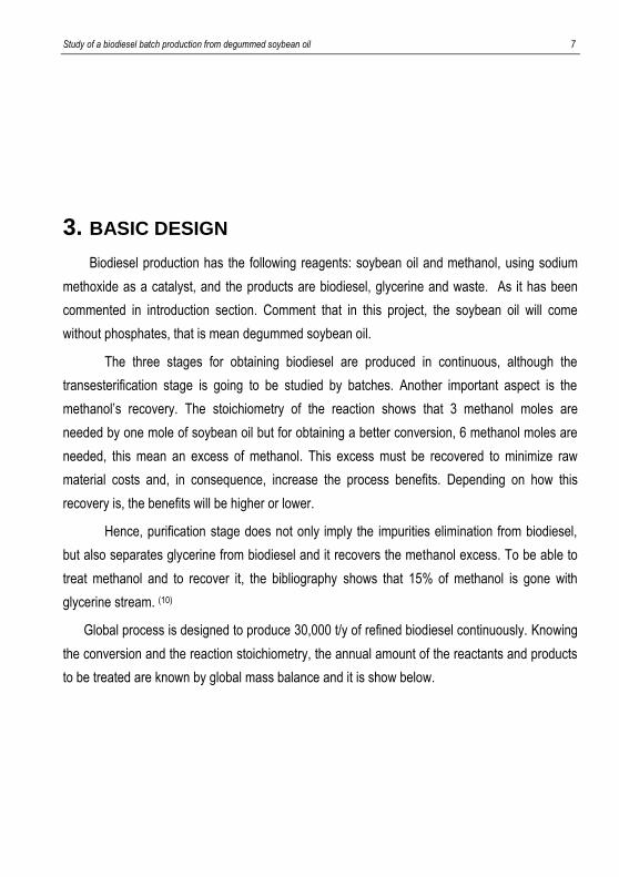
Global process is designed to produce 30,000 t/y of refined biodiesel continuously. Knowing
the conversion and the reaction stoichiometry, the annual amount of the reactants and products
to be treated are known by global mass balance and it is show below.
8 Ortiz Peláez, Ainhoa
Figure 3. Overall diagram of the inputs and outputs of Biodiesel production.
Stream in 1 2 3 Total
Mass [t/y] 32,714 4,969 75 37,758
Stream out 4 5 6 7 Total
Mass [t/y] 30,000 3,106 1,067 3,585 37,758
Table 3. Annual global mass balance.
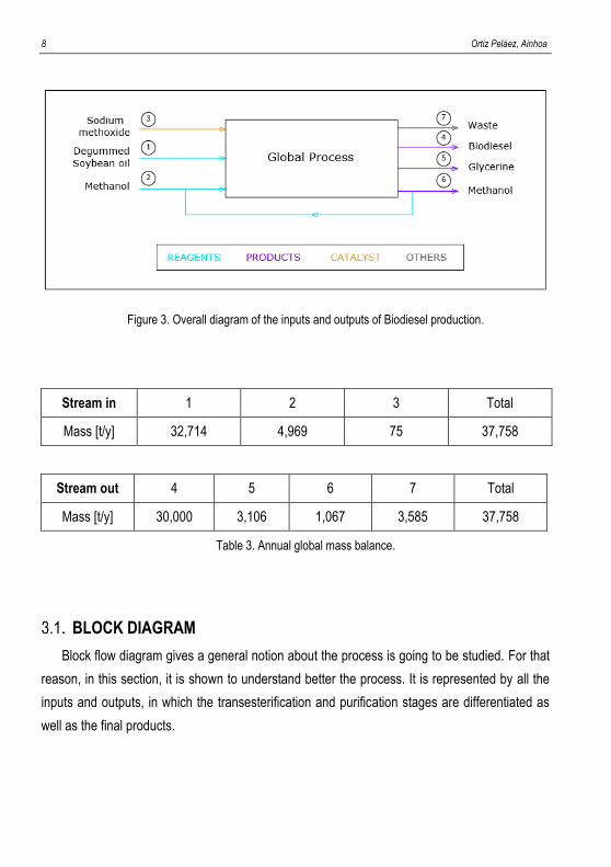
BLOCK DIAGRAM
Block flow diagram gives a general notion about the process is going to be studied. For that
reason, in this section, it is shown to understand better the process. It is represented by all the
inputs and outputs, in which the transesterification and purification stages are differentiated as
well as the final products.
Study of a biodiesel batch production from degummed soybean oil 9

10 Ortiz Peláez, Ainhoa
Study of a biodiesel batch production from degummed soybean oil 11
DESIGN BASES
Hereunder, the assumptions are shown that were used to develop the front-end engineering
design package to produce biodiesel from soybean oil.
- One of the aims of this project is producing 30,000 tonnes/year of refined biodiesel
(RB). This amount is the calculation base for the design of production process. In
addition, the biodiesel impurities will be set at 2.50% in non-refined biodiesel.
- All process stages are defined in continuously except one of them, transesterification
process is defined in discontinuous.
- The global process will be operating per batches, 330 out of 365 days by year, working
7 days/weeks (24 hours/day) for producing this amount of biodiesel. That means 7,920
hours/year.
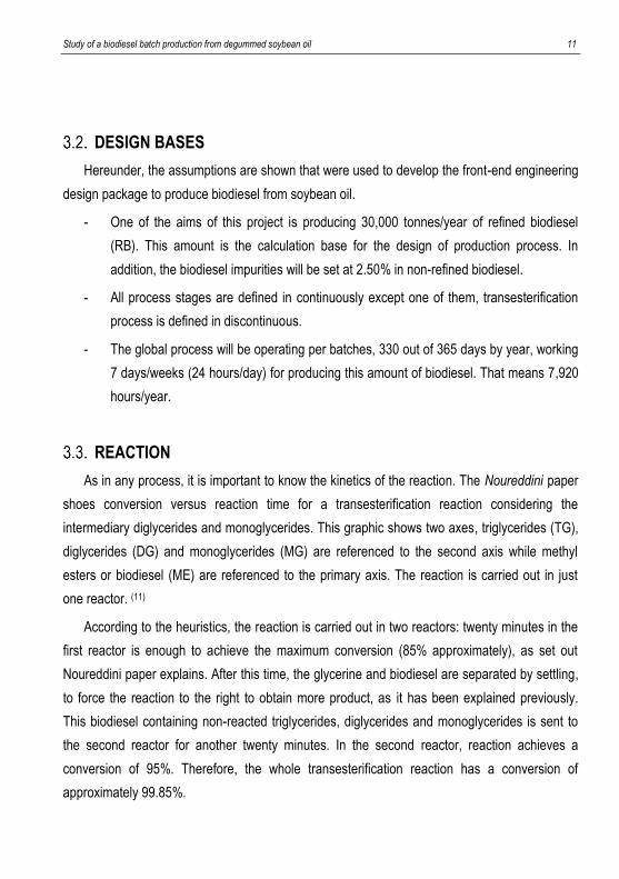
REACTION
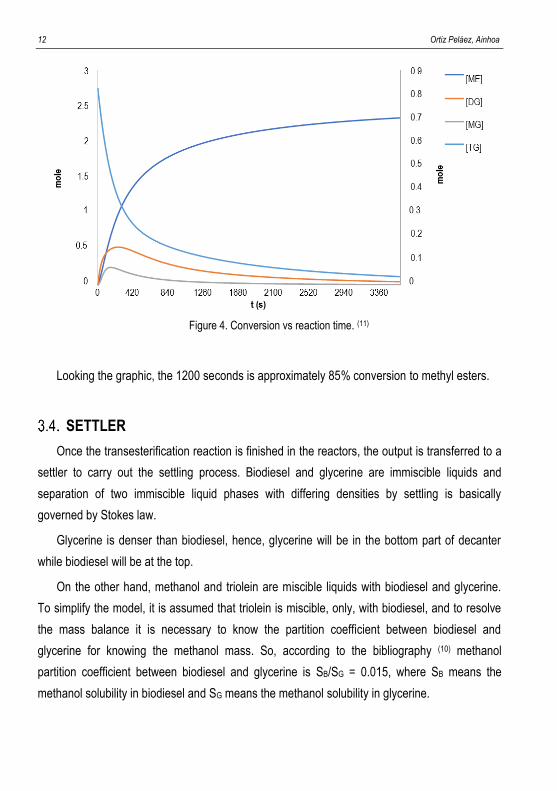
As in any process, it is important to know the kinetics of the reaction. The Noureddini paper
shoes conversion versus reaction time for a transesterification reaction considering the
intermediary diglycerides and monoglycerides. This graphic shows two axes, triglycerides (TG),
diglycerides (DG) and monoglycerides (MG) are referenced to the second axis while methyl
esters or biodiesel (ME) are referenced to the primary axis. The reaction is carried out in just
one reactor. (11)
According to the heuristics, the reaction is carried out in two reactors: twenty minutes in the
first reactor is enough to achieve the maximum conversion (85% approximately), as set out
Noureddini paper explains. After this time, the glycerine and biodiesel are separated by settling,
to force the reaction to the right to obtain more product, as it has been explained previously.
This biodiesel containing non-reacted triglycerides, diglycerides and monoglycerides is sent to
the second reactor for another twenty minutes. In the second reactor, reaction achieves a
conversion of 95%. Therefore, the whole transesterification reaction has a conversion of
approximately 99.85%.
12 Ortiz Peláez, Ainhoa
Figure 4. Conversion vs reaction time. (11)
Looking the graphic, the 1200 seconds is approximately 85% conversion to methyl esters.
SETTLER
Once the transesterification reaction is finished in the reactors, the output is transferred to a
settler to carry out the settling process. Biodiesel and glycerine are immiscible liquids and
separation of two immiscible liquid phases with differing densities by settling is basically
governed by Stokes law.
Glycerine is denser than biodiesel, hence, glycerine will be in the bottom part of decanter
while biodiesel will be at the top.
On the other hand, methanol and triolein are miscible liquids with biodiesel and glycerine.
To simplify the model, it is assumed that triolein is miscible, only, with biodiesel, and to resolve
the mass balance it is necessary to know the partition coefficient between biodiesel and
glycerine for knowing the methanol mass. So, according to the bibliography (10) methanol
partition coefficient between biodiesel and glycerine is SB/SG = 0.015, where SB means the
methanol solubility in biodiesel and SG means the methanol solubility in glycerine.
Study of a biodiesel batch production from degummed soybean oil 13
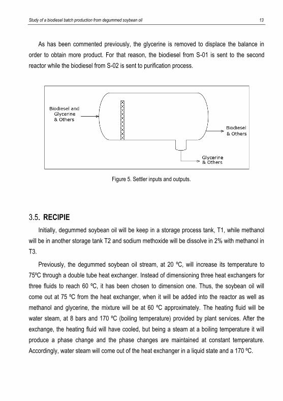
As has been commented previously, the glycerine is removed to displace the balance in
order to obtain more product. For that reason, the biodiesel from S-01 is sent to the second
reactor while the biodiesel from S-02 is sent to purification process.
Figure 5. Settler inputs and outputs.
RECIPIE
Initially, degummed soybean oil will be keep in a storage process tank, T1, while methanol
will be in another storage tank T2 and sodium methoxide will be dissolve in 2% with methanol in
T3.
Previously, the degummed soybean oil stream, at 20 ºC, will increase its temperature to
75ºC through a double tube heat exchanger. Instead of dimensioning three heat exchangers for
three fluids to reach 60 ºC, it has been chosen to dimension one. Thus, the soybean oil will
come out at 75 ºC from the heat exchanger, when it will be added into the reactor as well as
methanol and glycerine, the mixture will be at 60 ºC approximately. The heating fluid will be
water steam, at 8 bars and 170 ºC (boiling temperature) provided by plant services. After the
exchange, the heating fluid will have cooled, but being a steam at a boiling temperature it will
produce a phase change and the phase changes are maintained at constant temperature.
Accordingly, water steam will come out of the heat exchanger in a liquid state and a 170 ºC.
14 Ortiz Peláez, Ainhoa
After that, the reagents and the catalyst will be set to the first vessel, V-01. The reaction is
produced at atmospheric pressure and at a temperature of 60 ºC. For this reason, the vessel
will have a jacketed to keep the reactor temperature constant. The heating fluid will be water
steam, at 8 bars and 170 ºC the same as the heat exchanger.
Once the reaction is finished, to force the reaction to the products, the compounds will be
sent to a settler, S-01, to separate the immiscible phases of biodiesel and glycerine, considering
that all the triolein goes with the biodiesel. On the other hand, part of methanol dissolves in
glycerine and in biodiesel but, by distribution coefficients it is known that it is more soluble in
glycerine than in biodiesel. In any case, this solubility will be explained later in settler section.
The mixture will be allowed to cool until 50 ºC, where finally the separated non-refined
glycerine will go to a storage tank, T4, and the biodiesel phase will be sent to the second
reactor, V-02.
In the second reactor, the methanol and sodium methoxide amount necessary to carry out
the reaction is added. Working at the same conditions as the first vessel. It will also appear of a
jacketed whose heating fluid will be water steam at the same conditions as the first vessel too.
In the same way, the compounds will be sent to the second settle, S-02, where non-refined
glycerine phase will be sent to the same storage tank used in the first settler, T4. Rather, non-
refined biodiesel obtained will be store in another storage tank, T5.
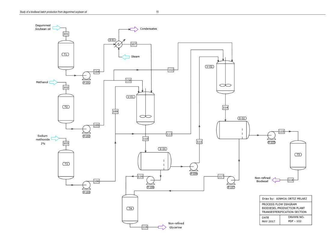
PROCESS FLOW DIAGRAM
Once the batch size has been chosen, 20,970 tonnes of non-refined biodiesel (NRB), as it
will be seen in section number 7, the mass balance has been solved for that batch size. Mass
balance and the process flow diagram for transesterification stage by batches is shown below.
Study of a biodiesel batch production from degummed soybean oil 15

16 Ortiz Peláez, Ainhoa
Study of a biodiesel batch production from degummed soybean oil 17
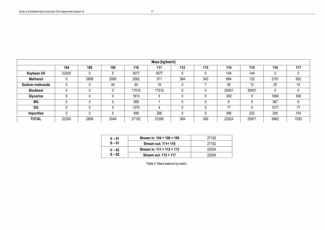
Table 4. Mass balance by batch.
Mass [kg/batch]
104 108 109 110 111 112 113 114 115 116 117
Soybean Oil 22300 0 0 3077 3077 0 0 144 144 0 0
Methanol 0 2808 2000 2562 371 384 343 684 132 2191 552
Sodium methoxide 0 0 44 44 19 0 7 26 12 25 15
Biodiesel 0 0 0 17515 17515 0 0 20451 20451 0 0
Glycerine 0 0 0 1813 5 0 0 309 0 1808 309
MG 0 0 0 368 1 0 0 6 0 367 6
DG 0 0 0 1275 4 0 0 17 0 1271 17
Impurities 0 0 0 498 298 0 0 386 232 200 154
TOTAL 22300 2808 2044 27152 21290 384 350 22024 20971 5862 1053
V – 01 S – 01
Stream in: 104 + 108 + 109 27152
Stream out: 111+ 116 27152
V – 02 S – 02
Stream in: 111 + 112 + 113 22024
Stream out: 115 + 117 22024

18 Ortiz Peláez, Ainhoa
Study of a biodiesel batch production from degummed soybean oil 19
4. PROJECT SPECIFICATIONS
In this section, it will be detailed the specifications of the mentioned equipments previously.
It will be talked about their size, materials and their auxiliary equipments in case they are
needed.
As it has been seen previously, the process has two vessels and two settlers. Both vessels
and settlers have the same dimensions due to economic and flexibility issues. Consequently,
the vessel’s auxiliary equipment will be the same for both.
Highlight that all the physical-chemical properties of the process have been found by the
chemical process optimization software Aspen Plus®.
The material used, for all equipments, will be stainless steel as it is known for its high
corrosion resistance. The most utilized are AISI 304 and AISI 316. The difference between them
is that 304 stainless steel contains 18% chromium and 8% nickel while 316 stainless steel
contains 16% chromium, 10% nickel and 2% molybdenum. With the molybdenum addition,
corrosion resistance is improved, proving a better corrosion resistance for 316 steel. In this
case, due to it is not corrosive fluids, AISI 304 will be chosen for all the equipments and pipes.
VESSELS V-01 AND V-02
In vessel V-01, the next stages take place: feeding of raw materials and reaction.
According to the legislation, the surface of those equipments through the interior of which
circulates a fluid at temperatures below 5 ºC or exceeding 50 ºC, should be isolated. Therefore,
the outside of the jacketed with glass wool of 100 mm thick, the amount used for this type of
process. (12)
Vessel’s design calculations can be seen with detail in the Appendix 2. However, the next
table contains a summary of his characteristics.
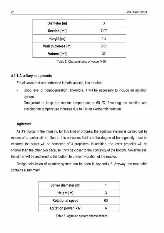
20 Ortiz Peláez, Ainhoa
Diameter [m] 3
Section [m2] 7.07
Height [m] 4.5
Wall thickness [m] 0.01
Volume [m3] 32
Table 5. Characteristics of vessel V-01.
4.1.1. Auxiliary equipments
For all tasks that are performed in both vessels, it is required:
- Good level of homogenization. Therefore, it will be necessary to include an agitation
system.
- One jacket to keep the reactor temperature at 60 ºC, favouring the reaction and
avoiding the temperature increase due to it is an exothermic reaction.
Agitators
As it’s typical in the industry, for this kind of process, the agitation system is carried out by
means of propeller stirrer. Due to it is a viscous fluid and the degree of homogeneity must be
ensured, the stirrer will be consisted of 3 propellers. In addition, the lower propeller will be
shorter than the other two because it will be closer to the concavity of the bottom. Nevertheless,
the stirrer will be anchored to the bottom to prevent vibration of the reactor.
Design calculation of agitation system can be seen in Appendix 2. Anyway, the next table
contains a summary.
Stirrer diameter [m] 1
Height [m] 3
Rotational speed 60
Agitation power [kW] 6
Table 6. Agitation system characteristics.
Study of a biodiesel batch production from degummed soybean oil 21
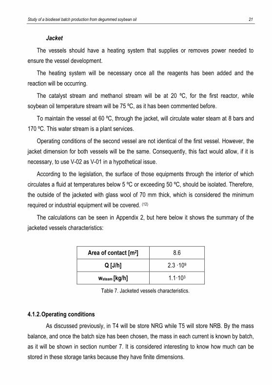
Jacket
The vessels should have a heating system that supplies or removes power needed to
ensure the vessel development.
The heating system will be necessary once all the reagents has been added and the
reaction will be occurring.
The catalyst stream and methanol stream will be at 20 ºC, for the first reactor, while
soybean oil temperature stream will be 75 ºC, as it has been commented before.
To maintain the vessel at 60 ºC, through the jacket, will circulate water steam at 8 bars and
170 ºC. This water stream is a plant services.
Operating conditions of the second vessel are not identical of the first vessel. However, the
jacket dimension for both vessels will be the same. Consequently, this fact would allow, if it is
necessary, to use V-02 as V-01 in a hypothetical issue.
According to the legislation, the surface of those equipments through the interior of which
circulates a fluid at temperatures below 5 ºC or exceeding 50 ºC, should be isolated. Therefore,
the outside of the jacketed with glass wool of 70 mm thick, which is considered the minimum
required or industrial equipment will be covered. (12)
The calculations can be seen in Appendix 2, but here below it shows the summary of the
jacketed vessels characteristics:
Area of contact [m2] 8.6
Q [J/h] 2.3 ·109
wsteam [kg/h] 1.1·103
Table 7. Jacketed vessels characteristics.
4.1.2. Operating conditions
As discussed previously, in T4 will be store NRG while T5 will store NRB. By the mass
balance, and once the batch size has been chosen, the mass in each current is known by batch,
as it will be shown in section number 7. It is considered interesting to know how much can be
stored in these storage tanks because they have finite dimensions.
22 Ortiz Peláez, Ainhoa
0
5000
10000
15000
20000
25000
0 1 2 3 4 5 6 7 8 9
Mas
s [k
g]
Time [h]
0
1000
2000
3000
4000
5000
6000
7000
8000
0 1 2 3 4 5 6 7 8
Mas
s [k
g]
Time [h]
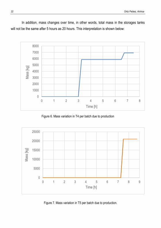
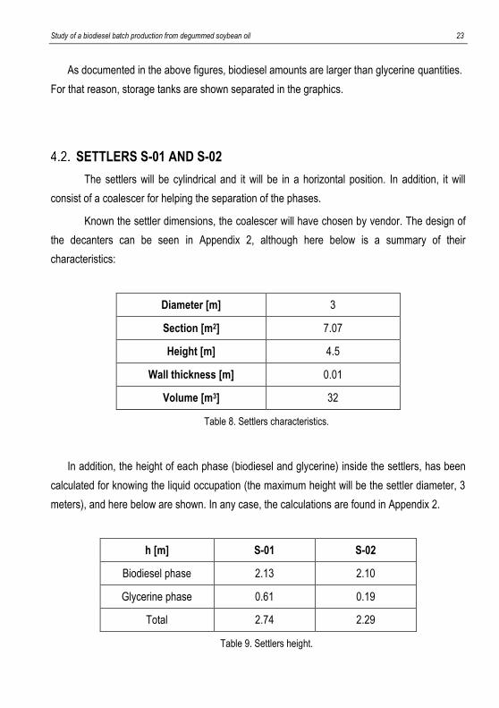
In addition, mass changes over time, in other words, total mass in the storages tanks
will not be the same after 5 hours as 20 hours. This interpretation is shown below:
Figure 6. Mass variation in T4 per batch due to production
Figure 7. Mass variation in T5 per batch due to production.
Study of a biodiesel batch production from degummed soybean oil 23
As documented in the above figures, biodiesel amounts are larger than glycerine quantities.
For that reason, storage tanks are shown separated in the graphics.
SETTLERS S-01 AND S-02
The settlers will be cylindrical and it will be in a horizontal position. In addition, it will
consist of a coalescer for helping the separation of the phases.
Known the settler dimensions, the coalescer will have chosen by vendor. The design of
the decanters can be seen in Appendix 2, although here below is a summary of their
characteristics:
Diameter [m] 3
Section [m2] 7.07
Height [m] 4.5
Wall thickness [m] 0.01
Volume [m3] 32
Table 8. Settlers characteristics.
In addition, the height of each phase (biodiesel and glycerine) inside the settlers, has been
calculated for knowing the liquid occupation (the maximum height will be the settler diameter, 3
meters), and here below are shown. In any case, the calculations are found in Appendix 2.
h [m] S-01 S-02
Biodiesel phase 2.13 2.10
Glycerine phase 0.61 0.19
Total 2.74 2.29
Table 9. Settlers height.
24 Ortiz Peláez, Ainhoa
Comment that in the decanter the liquid-liquid mixture will have cooled up to 50 ºC. As it
has been mentioned above, if inside of the any equipment exceeds 50 ºC, the equipment must
be isolated. For that reason, the settlers will not be insulated.
HEAT EXCHANGER
In order to select the type of heat exchanger, the next factors must be considered: thermal
and hydraulic requirements, operating conditions, cleaning of the exchange, available space,
tolerable weight, economics aspects. (13) Thermal and hydraulic requirements mean it is
necessary to know the amount of heat that should be exchanged. In addition, heat transfer is
always linked to the pressure drop experienced by the fluids.
Considering these factors, a shell-and-tube exchanger has been chosen. The
characteristics of this heat exchanger are: (13)
- It allows to operate a wide range of pressure and temperature.
- It can be used for many functions, including phase change.
- Depending on the operation’s needs, is built with various types of materials.
- Construction methods are standardized by TEMA (Tubular Exchanger Manufacturers
Association).
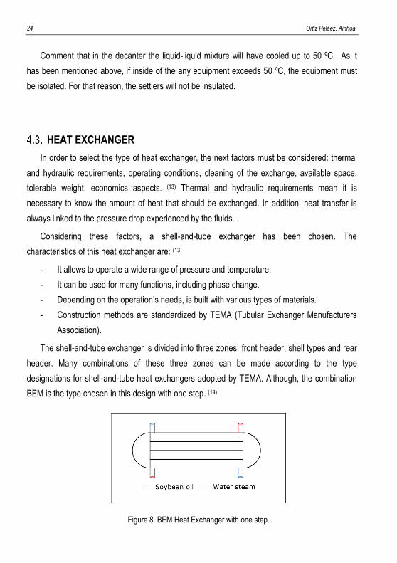
The shell-and-tube exchanger is divided into three zones: front header, shell types and rear
header. Many combinations of these three zones can be made according to the type
designations for shell-and-tube heat exchangers adopted by TEMA. Although, the combination
BEM is the type chosen in this design with one step. (14)
Figure 8. BEM Heat Exchanger with one step.
Study of a biodiesel batch production from degummed soybean oil 25
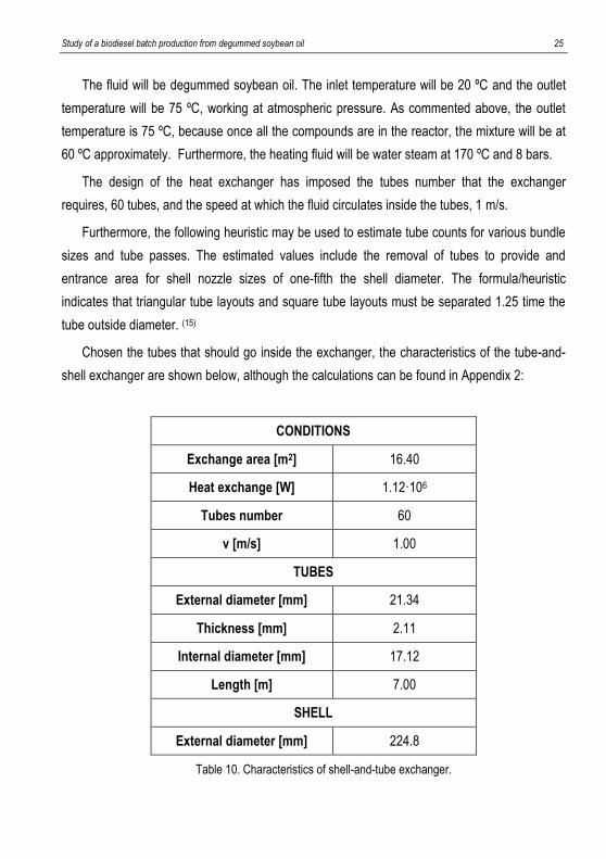
The fluid will be degummed soybean oil. The inlet temperature will be 20 ºC and the outlet
temperature will be 75 ºC, working at atmospheric pressure. As commented above, the outlet
temperature is 75 ºC, because once all the compounds are in the reactor, the mixture will be at
60 ºC approximately. Furthermore, the heating fluid will be water steam at 170 ºC and 8 bars.
The design of the heat exchanger has imposed the tubes number that the exchanger
requires, 60 tubes, and the speed at which the fluid circulates inside the tubes, 1 m/s.
Furthermore, the following heuristic may be used to estimate tube counts for various bundle
sizes and tube passes. The estimated values include the removal of tubes to provide and
entrance area for shell nozzle sizes of one-fifth the shell diameter. The formula/heuristic
indicates that triangular tube layouts and square tube layouts must be separated 1.25 time the
tube outside diameter. (15)
Chosen the tubes that should go inside the exchanger, the characteristics of the tube-and-
shell exchanger are shown below, although the calculations can be found in Appendix 2:
CONDITIONS
Exchange area [m2] 16.40
Heat exchange [W] 1.12·106
Tubes number 60
v [m/s] 1.00
TUBES
External diameter [mm] 21.34
Thickness [mm] 2.11
Internal diameter [mm] 17.12
Length [m] 7.00
SHELL
External diameter [mm] 224.8
Table 10. Characteristics of shell-and-tube exchanger.
26 Ortiz Peláez, Ainhoa
VALVES & PIPES
Valves
In this project two types of valves are clearly differentiated, ball valves and butterfly valves.
The last one, it is the control valves.
Process plants consist of a lot of control loops all networked together. Each of these control
loops is designed to keep some important process variable such as pressure, level,
temperature, etc. The problem is the process has disturbances that influence the process
variable. For that reason, the most common final control element in the process control
industries is the control valve. The control valve manipulates a flowing fluid to compensate for
the load disturbance and keep the regulated process variable as chose as possible to the
desired set point. (16)
A ball valve is a form of quarter-turn valve which uses a hollow perforated and pivoting ball
to control flow through it. It is open when the ball’s hole is in line with the flow and closed when it
is pivoted 90 degrees by the valve handle. The handle lies flat in alignment with the flow when
open, and it is perpendicular to it when is closed. There are valves closing securely even after
long periods of disuse. For that reason, these kinds of valves are excellent choice for shutoff
valves. Moreover, supporting pressures up to 1000 bar and temperatures up to 400 ºC,
depending on design and materials used. (16)
A butterfly valve is a valve that isolates or regulates the flow of a fluid. Operation is similar to
that of a ball valve, which allows for quick shut off. The disc is positioned in the center of the
pipe. A rod passes through the disc to an actuator on the outside of the valve. Rotating the
actuator turns the disc either parallel or perpendicular to the flow. Unlike a bell valve, the disc is
always present within the flow, so it induces a pressure drop, even when open. (16)
Pipes
Initially a speed has been imposed to know the pipes dimensions, knowing that the fluid
velocity should be between 1 and 2 m/s. The lowest has been chosen. It has to be taken into
account that reducing the speed, increases the diameter and, consequently, reduces pressure
drop.
Study of a biodiesel batch production from degummed soybean oil 27
Subsequently, through a pipeline catalogue, piping’s have been selected according to the
calculated dimensions. Therefore, next step is to recalculate the speed to know if it is between
commented interval. All the calculations can be found in Appendix 2.
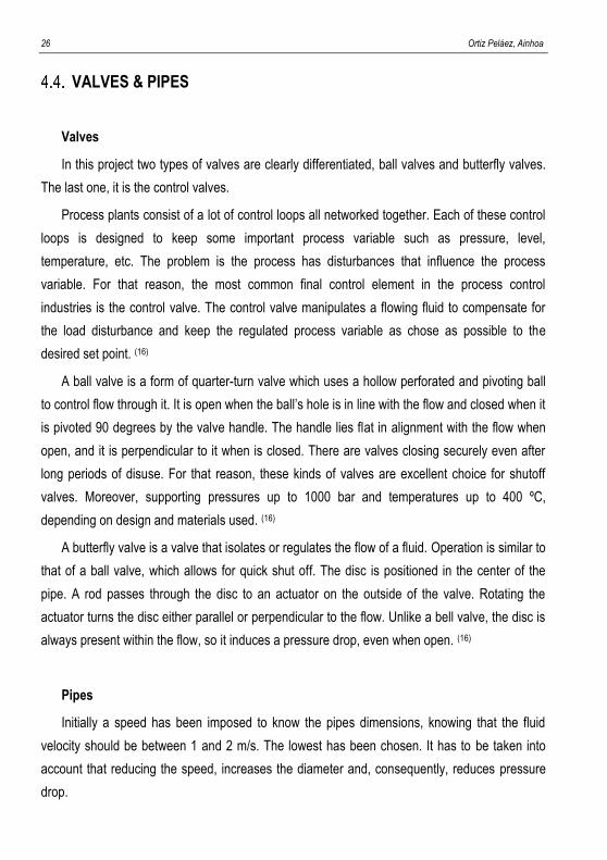
Thus, the pipes dimensions are:
104 a 105 b 117 c
dext (mm) 114.30 48.26 21.36
e (mm) 3.05 2.77 2.11
dint (mm) 108.20 42.72 17.14
Table 11. Pipe dimensioning.
a. Pipes number: 104, 107, 110, 111, 114 and 115 have the same dimensions.
b. Pipes number: 105, 106, 108, 109, 112, 113 and 116 have the same dimensions.
c. Pipe number 117 has these dimensions.
PUMPS
Generally, there are two types of pumps: centrifugal and positive displacement pumps.
Although centrifugal pumps are the most common, positive displacement come in a wider
variety such as: gear, lobe, screw, etc. (17)
Main difference between these two types of pumps is that centrifugal pumps create a
pressure differential resulting in flow, while, positive displacement pumps, the pressure
differential results from flow created by the pump. (18)
Pumps are usually chosen by a vendor; different data must be submitted to the company to
be able to choose the pump type. The vendor needs date such as:
- Pressure difference (Pump ΔP). Pressure at the beginning and at the end of the pump.
- Total dynamic head (Pump TDH). The total equivalent height that a fluid is to be
pumped, taking into account friction losses in the pipe.
- NSPH (Net Positive Suction Head). It helps to know the proximity of the installation to
the cavitation.
28 Ortiz Peláez, Ainhoa
Cavitation is a hydrodynamic effect. It occurs when the fluid, in liquid phase, rushes into the
pump so fast and produces a fluid decompression. In other words, when vapor pressure is
reached, the molecules immediately change to gaseous state and form bubbles known as
cavities. Therefore, the pressure in the stream in must be greater than the vapor pressure of the
mixture inside the pump. The NPSH amount of the process must always be greater than the
NSPH amount provided by the manufacturer.
In this project, centrifugal pumps have been selected because for these characteristics and
operation condition, the most used in the industry are centrifuges pumps. Moreover, the toxicity
and corrosivity of the material and the fluid are low.
PLANT SERVICES
The following points will be offered by plant services:
- Water steam. During the process, and average pressure of 8 bars is required for the
heating fluid for carrying out the temperature increase of degummed soybean oil input.
Also, it is used to keep the vessel temperature constant at 60 ºC.
- Nitrogen stream. It will be used to inert storage tanks, T2 and T3, and vessels, V-01
and V-02, when it will be necessary. Moreover, in the vessels are used to download
faster. In other words, according to Bernoulli equation, for closed containers, discharge
velocity is independent of the diameter of the pipe (the opposite of the open containers)
but providing more pressure it will lead to discharge faster.
- Cooling water. It refers to the water used for cooling processes such a public channel
catchment water (rivers, lakes, etc), seawater and cooling tower circuit water (natural
or forced draft, in this case, the design variable is the we bulb temperature of the zone.
Study of a biodiesel batch production from degummed soybean oil 29
STORAGE TANKS
It is important to know that storage tanks T1, T2, T3 are process tanks. In other words, the
storage quantities come from larger tanks. This means that these tanks are designed for
keeping the mass between 1 – 3 days. Hence, T1 will be designed for working one day while T2
and T3 will be designed for working 3 days.
By contrast, the sizing of the storage tanks T4 and T5 comes from an optimization.
Depending on the operation mode of the plant will have one dimensions or others, as it will be
seen in section 7.
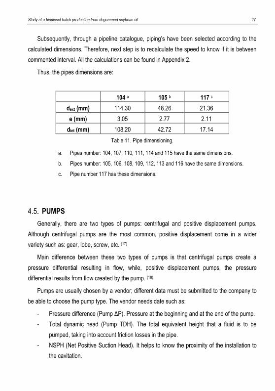
However, the dimensions are shown below:
Storage Tank T1 T2 T3 T4 T5
Volume [m3] 180 80 60 130 405
Table 12. Storage tanks dimensions.
By mass balance, the necessary amount of degummed soybean oil, methanol, and sodium
methoxide diluted 2% is known. Knowing the batch time (it will be seen in section 7) and the
days that each tank is going to store, the total mass is known. Volume is relating with the mass
through the density, so knowing the mass and the density, volume shall be set.
Furthermore, it should be commented that for T4 an T5 tanks will be composed of two tanks
each. The total stored volume for T4 will be 130 m3, and for T5, 405 m3.
The fact of having two tanks instead of one is for the operation strategy, while one is filling
up, the other one is discharging.

30 Ortiz Peláez, Ainhoa
Study of a biodiesel batch production from degummed soybean oil 31
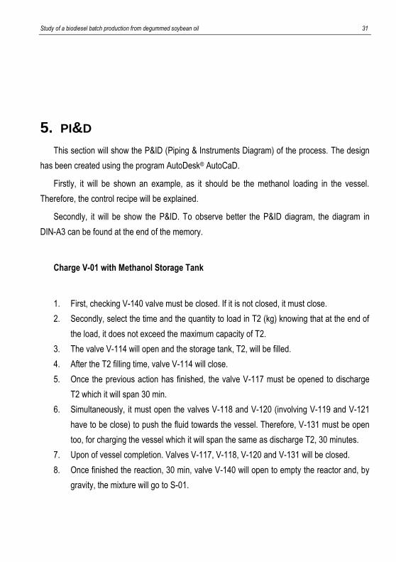
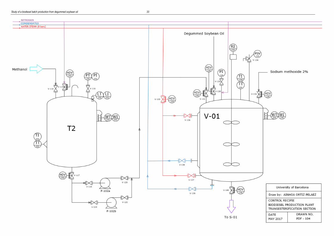
5. PI&D
This section will show the P&ID (Piping & Instruments Diagram) of the process. The design
has been created using the program AutoDesk® AutoCaD.
Firstly, it will be shown an example, as it should be the methanol loading in the vessel.
Therefore, the control recipe will be explained.
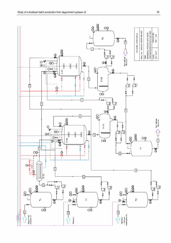
Secondly, it will be show the P&ID. To observe better the P&ID diagram, the diagram in
DIN-A3 can be found at the end of the memory.
Charge V-01 with Methanol Storage Tank
1. First, checking V-140 valve must be closed. If it is not closed, it must close.
2. Secondly, select the time and the quantity to load in T2 (kg) knowing that at the end of
the load, it does not exceed the maximum capacity of T2.
3. The valve V-114 will open and the storage tank, T2, will be filled.
4. After the T2 filling time, valve V-114 will close.
5. Once the previous action has finished, the valve V-117 must be opened to discharge
T2 which it will span 30 min.
6. Simultaneously, it must open the valves V-118 and V-120 (involving V-119 and V-121
have to be close) to push the fluid towards the vessel. Therefore, V-131 must be open
too, for charging the vessel which it will span the same as discharge T2, 30 minutes.
7. Upon of vessel completion. Valves V-117, V-118, V-120 and V-131 will be closed.
8. Once finished the reaction, 30 min, valve V-140 will open to empty the reactor and, by
gravity, the mixture will go to S-01.

32 Ortiz Peláez, Ainhoa
Study of a biodiesel batch production from degummed soybean oil 33

34 Ortiz Peláez, Ainhoa
Study of a biodiesel batch production from degummed soybean oil 35

36 Ortiz Peláez, Ainhoa
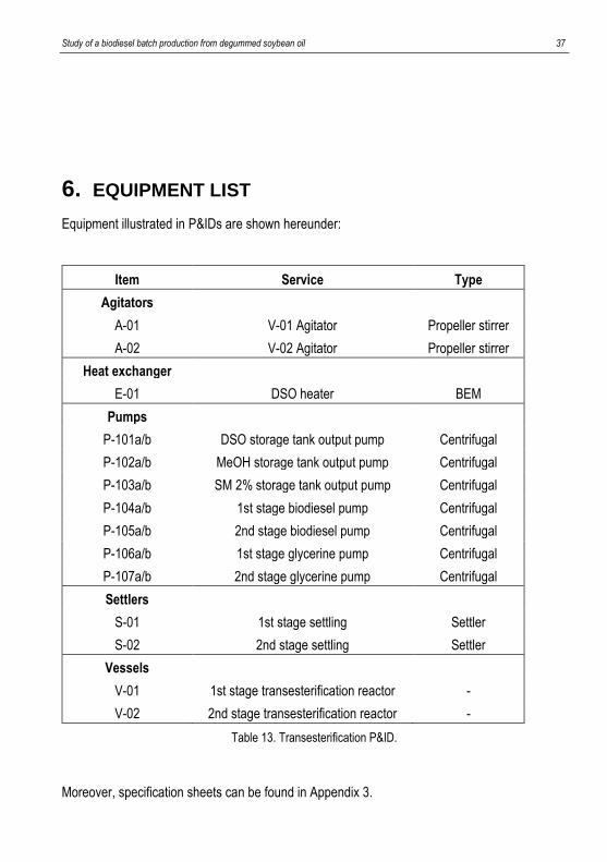
Study of a biodiesel batch production from degummed soybean oil 37
6. EQUIPMENT LIST
Equipment illustrated in P&IDs are shown hereunder:
Item Service Type
Agitators A-01 V-01 Agitator Propeller stirrer
A-02 V-02 Agitator Propeller stirrer
Heat exchanger E-01 DSO heater BEM
Pumps P-101a/b DSO storage tank output pump Centrifugal
P-102a/b MeOH storage tank output pump Centrifugal
P-103a/b SM 2% storage tank output pump Centrifugal
P-104a/b 1st stage biodiesel pump Centrifugal
P-105a/b 2nd stage biodiesel pump Centrifugal
P-106a/b 1st stage glycerine pump Centrifugal
P-107a/b 2nd stage glycerine pump Centrifugal
Settlers S-01 1st stage settling Settler
S-02 2nd stage settling Settler
Vessels V-01 1st stage transesterification reactor -
V-02 2nd stage transesterification reactor -
Table 13. Transesterification P&ID.
Moreover, specification sheets can be found in Appendix 3.

38 Ortiz Peláez, Ainhoa
Study of a biodiesel batch production from degummed soybean oil 39
7. SCHEDULING
Once known in depth the process, it has made the equipments sizing and it has decided
which tasks will be carried out in each, it is time to set the pace of production to achieve the
annual of product to produce.
GENERAL CONSIDERATIONS
Scheduling is a critical issue in process operations and is crucial for improving production
performance. For batch processes, short-term scheduling deals with the allocation of a set of
limited resources over time to manufacture one or more products following a batch recipe.
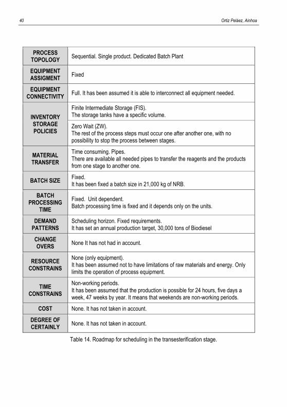
There are a great variety of aspects that need to be considered when developing scheduling
models for batch processes. In order to provide a systematic characterization a general
roadmap for classifying most relevant problem features is summarized in Table 14 and
considers not only equipment and material issues, but also time and demand-related constrains.
As can be seen, the main features involve 13 major categories, each of which are linked to
central problem characteristics. (19) The results of the application of the roadmap in this project is
showed in the same Table 14.
It should be stressed that the annual production of 30,000 tonnes of refined biodiesel
correspond to the annual mass balance, that it involves that 30,764 tonnes of non-refined
biodiesel (NRB) are required in the annual production of the transesterification stage.
Although the purification process of the biodiesel and the methanol recovery are carried out
continuously (330 days per year, 24 h/day), the transesterification section is carried out per
batch. It is proposed to work 5 days per week in 3 shifts per day and a total of 47 weeks per
year. Therefore, the weekends will only work the purification section and the methanol recovery.
40 Ortiz Peláez, Ainhoa
PROCESS TOPOLOGY
Sequential. Single product. Dedicated Batch Plant
EQUIPMENT ASSIGMENT
Fixed
EQUIPMENT CONNECTIVITY
Full. It has been assumed it is able to interconnect all equipment needed.
INVENTORY STORAGE POLICIES
Finite Intermediate Storage (FIS). The storage tanks have a specific volume.
Zero Wait (ZW). The rest of the process steps must occur one after another one, with no possibility to stop the process between stages.
MATERIAL TRANSFER
Time consuming. Pipes. There are available all needed pipes to transfer the reagents and the products from one stage to another one.
BATCH SIZE Fixed. It has been fixed a batch size in 21,000 kg of NRB.
BATCH PROCESSING
TIME
Fixed. Unit dependent. Batch processing time is fixed and it depends only on the units.
DEMAND PATTERNS
Scheduling horizon. Fixed requirements. It has set an annual production target, 30,000 tons of Biodiesel
CHANGE OVERS
None It has not had in account.
RESOURCE CONSTRAINS
None (only equipment). It has been assumed not to have limitations of raw materials and energy. Only limits the operation of process equipment.
TIME CONSTRAINS
Non-working periods. It has been assumed that the production is possible for 24 hours, five days a week, 47 weeks by year. It means that weekends are non-working periods.
COST None. It has not taken in account.
DEGREE OF CERTAINLY
None. It has not taken in account.
Table 14. Roadmap for scheduling in the transesterification stage.
Study of a biodiesel batch production from degummed soybean oil 41
The difficulty is finding a batch size it allows to get 30,764 t/y of NRB. To get it, an iteration
is required to find a suitable batch size for the required working conditions. So, it is necessary to
determine the batch size. Stressing that roadmap is an iterative process, firstly, a value is
assumed. Secondly, the scheduling resolution is carried out and, finally it is checked if the
obtained values fulfil all the problem restrictions. After a study, the batch size of 20,970 kg of
NRB per batch was chosen. In addition, it will allow to work with more flexibility as it will be
shown later.
BATCH TIME
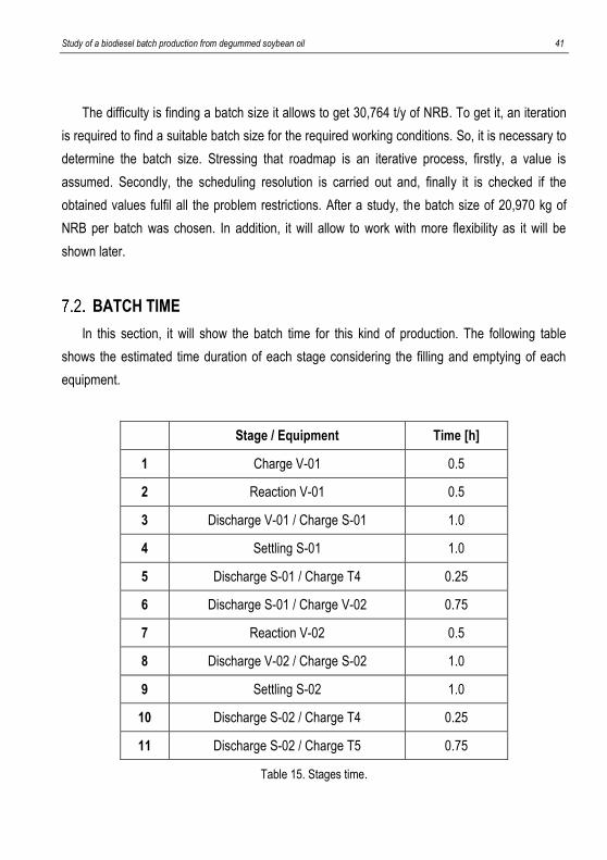
In this section, it will show the batch time for this kind of production. The following table
shows the estimated time duration of each stage considering the filling and emptying of each
equipment.
Stage / Equipment Time [h]
1 Charge V-01 0.5
2 Reaction V-01 0.5
3 Discharge V-01 / Charge S-01 1.0
4 Settling S-01 1.0
5 Discharge S-01 / Charge T4 0.25
6 Discharge S-01 / Charge V-02 0.75
7 Reaction V-02 0.5
8 Discharge V-02 / Charge S-02 1.0
9 Settling S-02 1.0
10 Discharge S-02 / Charge T4 0.25
11 Discharge S-02 / Charge T5 0.75
Table 15. Stages time.
42 Ortiz Peláez, Ainhoa
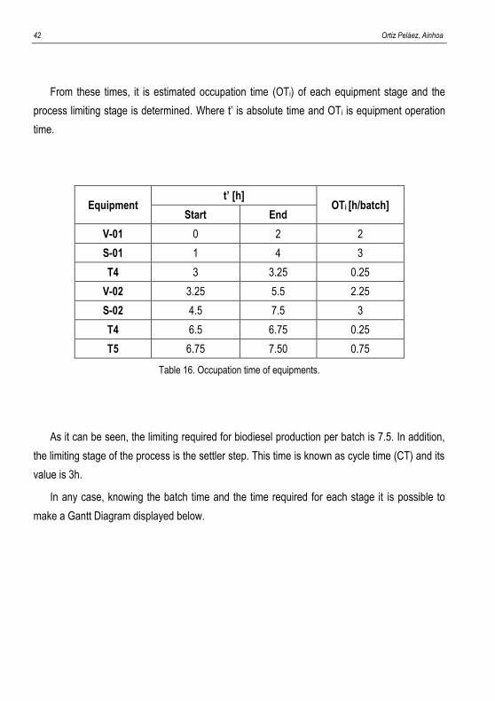
From these times, it is estimated occupation time (OTi) of each equipment stage and the
process limiting stage is determined. Where t’ is absolute time and OTi is equipment operation
time.
Equipment t’ [h]
OTi [h/batch] Start End
V-01 0 2 2
S-01 1 4 3
T4 3 3.25 0.25
V-02 3.25 5.5 2.25
S-02 4.5 7.5 3
T4 6.5 6.75 0.25
T5 6.75 7.50 0.75
Table 16. Occupation time of equipments.
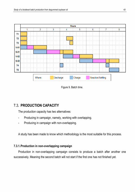
As it can be seen, the limiting required for biodiesel production per batch is 7.5. In addition,
the limiting stage of the process is the settler step. This time is known as cycle time (CT) and its
value is 3h.
In any case, knowing the batch time and the time required for each stage it is possible to
make a Gantt Diagram displayed below.
Study of a biodiesel batch production from degummed soybean oil 43
Figure 9. Batch time.
PRODUCTION CAPACITY
The production capacity has two alternatives:
- Producing in campaign, namely, working with overlapping.
- Producing in campaign with non-overlapping.
A study has been made to know which methodology is the most suitable for this process.
7.3.1. Production in non-overlapping campaign
Production in non-overlapping campaign consists to produce a batch after another one
successively. Meaning the second batch will not start if the first one has not finished yet.
44 Ortiz Peláez, Ainhoa
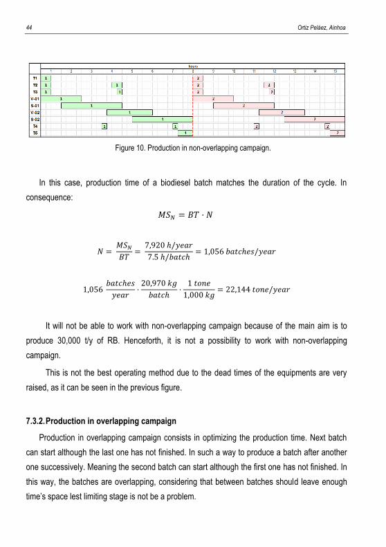
Figure 10. Production in non-overlapping campaign.
In this case, production time of a biodiesel batch matches the duration of the cycle. In
consequence:
𝑀𝑆𝑁 = 𝐵𝑇 · 𝑁
𝑁 = 𝑀𝑆𝑁
𝐵𝑇=
7,920 ℎ/𝑦𝑒𝑎𝑟
7.5 ℎ/𝑏𝑎𝑡𝑐ℎ= 1,056 𝑏𝑎𝑡𝑐ℎ𝑒𝑠/𝑦𝑒𝑎𝑟
1,056 𝑏𝑎𝑡𝑐ℎ𝑒𝑠
𝑦𝑒𝑎𝑟·
20,970 𝑘𝑔
𝑏𝑎𝑡𝑐ℎ·
1 𝑡𝑜𝑛𝑒
1,000 𝑘𝑔= 22,144 𝑡𝑜𝑛𝑒/𝑦𝑒𝑎𝑟
It will not be able to work with non-overlapping campaign because of the main aim is to
produce 30,000 t/y of RB. Henceforth, it is not a possibility to work with non-overlapping
campaign.
This is not the best operating method due to the dead times of the equipments are very
raised, as it can be seen in the previous figure.
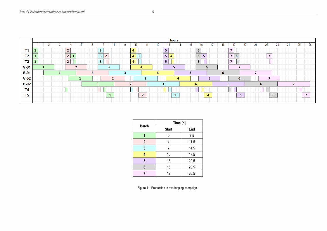
7.3.2. Production in overlapping campaign
Production in overlapping campaign consists in optimizing the production time. Next batch
can start although the last one has not finished. In such a way to produce a batch after another
one successively. Meaning the second batch can start although the first one has not finished. In
this way, the batches are overlapping, considering that between batches should leave enough
time’s space lest limiting stage is not be a problem.
Study of a biodiesel batch production from degummed soybean oil 45
Batch Time [h]
Start End
1 0 7.5
2 4 11.5
3 7 14.5
4 10 17.5
5 13 20.5
6 16 23.5
7 19 26.5
Figure 11. Production in overlapping campaign.

46 Ortiz Peláez, Ainhoa
Study of a biodiesel batch production from degummed soybean oil 47
HIGHEST CAPACITY
Highlight that optimizing time is seen the first reactor charge in the second batch, it
begins before that the second reactor charge in the first batch.
As it has been commented before, CT is “cycle time” and it refers to the longer time per
batch in biodiesel production. In consequence:
𝑀𝑆𝑁 = 𝐵𝑇 + (𝑁 − 1) · 𝐶𝑇
𝑁 = 𝑀𝑆𝑁 − 𝐵𝑇
𝐶𝑇+ 1 =
7,920 ℎ/𝑦𝑒𝑎𝑟 − 7.5 ℎ/𝑏𝑎𝑡𝑐ℎ
3 ℎ/𝑏𝑎𝑡𝑐ℎ+ 1 = 2,638 𝑏𝑎𝑡𝑐ℎ𝑒𝑠/𝑦𝑒𝑎𝑟
2,638 𝑏𝑎𝑡𝑐ℎ𝑒𝑠
𝑦𝑒𝑎𝑟·
20,970 𝑘𝑔
𝑏𝑎𝑡𝑐ℎ·
1 𝑡𝑜𝑛𝑒
1,000 𝑘𝑔= 52,760 𝑡𝑜𝑛𝑒/𝑦𝑒𝑎𝑟
It will be able to work with overlapping campaign because one of the main aim is to produce
30,764 t/y of non-refined biodiesel and it is being obtained 53,000 t/y roughly. So, working 330
days per year, 7 days by week, the maximum capacity of the plant will be 53,000 t/y of NRB.
The difficulty is producing 30,000 t/y of RB, involving 30,764 t/y NRB. If the plnat works 7
days by week (highest capacity), it is required:
30,764𝑡
𝑦·
1 𝑦
7,920 ℎ·
24 ℎ
1 𝑑𝑎𝑦·
7 𝑑𝑎𝑦𝑠
1 𝑤𝑒𝑒𝑘= 653 𝑡/𝑤
To produce 653 t/w it needs:
653𝑡
𝑤·
1,000 𝑘𝑔
1 𝑡·
1 𝑏𝑎𝑡𝑐ℎ
20,970 𝑘𝑔= 31.14
𝑏𝑎𝑡𝑐ℎ𝑒𝑠
𝑤𝑒𝑒𝑘
48 Ortiz Peláez, Ainhoa
By contrast, as it has been commented before. The transesterification stages works 5 days
per week with a batch size of 20,970 kg/batch of NRB, producing annually 30,764 t/y of NRB, it
is required:
5 𝑑𝑎𝑦𝑠
𝑤𝑒𝑒𝑘·
24 ℎ
1 𝑑𝑎𝑦= 120
ℎ
𝑑
𝑁 = 𝑀𝑆𝑁 − 𝐵𝑇
𝐶𝑇+ 1 =
120 − 7.5
3+ 1 = 38 𝑏𝑎𝑡𝑐ℎ𝑒𝑠/𝑤𝑒𝑒𝑘
38𝑏𝑎𝑡𝑐ℎ
𝑤𝑒𝑒𝑘·
20,970 𝑘𝑔
1 𝑏𝑎𝑡𝑐ℎ·
1 𝑡
1,000 𝑘𝑔= 796.86 𝑡/𝑤
Working 7 days per week is required 653 t/w while working 5 days is produced 796.86 t/y.
To set up, there is an overcapacity as it can been seen in the previous calculations.
Overcapacity is related to an excess of time. This excess can be destined, for example, in case
of incidence it will have the necessary time to act.
So, working 5 days per week, 47 weeks per year means that it needs 1467 batch/year to
carry out 30,764 of NRB.
DETERMINATION OF THE OPERATION STRATEGY
It will work on overlapping campaign, to a maximum of 120 hours per week. It is not going to
work at the maximum capacity of the plant. It is decided the plant must have one day of safety
stock. This represents a restriccion against the model. This safety stock will be 94 tonnes. It is
not going to be below that amount.
In normal coditions to produce 653 tonnes per week, 31.9 batches are nedded, so there are
two options. The transesterification stage can either produce 31 batches or 32.
It is observed that working with 32, production exceeds (causing an increase in the security
stock), and 31 batches, the required production is reached (the safety stock is consumed).
Therefore, both options have to be blended throughout the year.
Study of a biodiesel batch production from degummed soybean oil 49
Two production possibilities will be studied:
- Working in a single campaign per week with 31/32 batches.
- Working in two campaigns per week with an intermediate shutdown, with 31/32
batches per week.
It should be highlighted that the following sections is going to be discussed the
determination of the operation mode of the NRB storage tank, as an example. Thus, it will be
possible to know the tank volume. Once the T5 sizing has been deermined, the T4 sizing is
going to be commented.
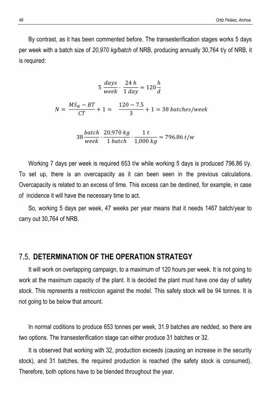
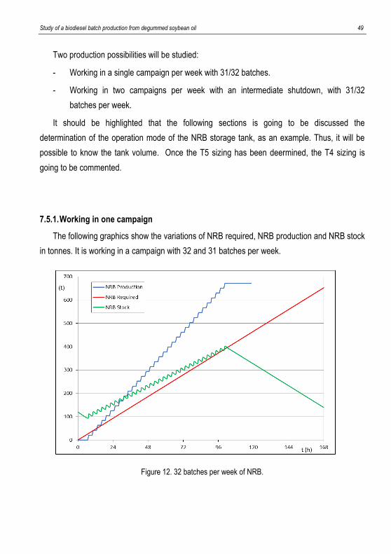
7.5.1. Working in one campaign
The following graphics show the variations of NRB required, NRB production and NRB stock
in tonnes. It is working in a campaign with 32 and 31 batches per week.
Figure 12. 32 batches per week of NRB.
50 Ortiz Peláez, Ainhoa
Figure 13. 31 batches per week of NRB.
If the stock line is observed, the NRB stock, and therefore, the volume to be stored is
very high. The storage tank should be designed to have a maximum NRB stock of 400 tonnes
per week. If it is related ti density, the required volume would be approximately 455 m3 in both
cases.
On the other hand, the maximum time worked is 120 hours. Working on a campaign of 31
and 32 batches, effective process time and non-effective process time are show below:
MS32 MS31
Effective process time [h] 100.5 97.7
Non-effective process time [h] 19.5 22.5
Table 17. Effetive and non-effective process time in one campaign.
Non-effective process time can be used for cleaning and maintenance work. Note that form
98 hours, at the beginning of the fifth day, the NRB production is stopped and the NRB stock is
started to be consumed.
Study of a biodiesel batch production from degummed soybean oil 51
7.5.2. Working in two campaign
In this case, it is worked in two campaigns, the first is with 15 and 17 batches (MS15/MS17),
and the second with 15 and 16 batches (MS15/MS16).It must be taken into account that if
campaigns increase, the make span is graer, therefore more time is lost. Hereunder, the
effective and non-effective process time is shown:
MS15/MS17 MS15/MS16
Effective process time [h] 105 102
Non-effective process time [h] 15 18
Table 18. Effetive and non-effective process time in tow campaigns.
It has been decided that the intermediate shutdown will be 10 hours. In te case of producing
31 batches (MS15/MS16), it will remain 5 hours for maintenance and cleaning at the of the
campaign and, in the case of 32 batches (MS15/MS17), it will remain 8 hours for maintenance
and cleaning.
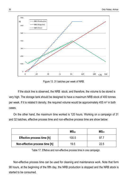
In the same way as working in one campaign, the NRB production, NRB required and NRB
stock working in wo campaigns are shown:
Figure 14. Weekly production of 15 and 17 batches of NRB with an intermediate shutdown.
52 Ortiz Peláez, Ainhoa
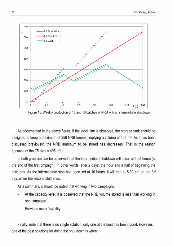
Figure 15. Weekly production of 15 and 16 batches of NRB with an intermediate shutdown.
As documented in the above figure, if the stock line is observed, the storage tank should be
designed to keep a maximum of 356 NRB tonnes, implying a volume of 405 m3. As it has been
discussed previously, the NRB ammount to be stored has decreases. That is the reason
because of the T5 size is 405 m3.
In both graphics can be observed that the intermediate shutdown will occur at 49.5 hours (at
the end of the first cmpaign). In other words, after 2 days, the hour and a half of beginning the
third day. As the intermediate stop has been set at 10 hours, it will end at 5.30 pm on the 3rd
day, when the second shift ends.
As a summary, it should be noted that working in two campaigns:
- At the capacity level, it is observed that the NRB volume stored is less than working in
one campaign.
- Provides more flexibility.
Finally, note that there is no single solution, only one of the best has been found. However,
one of the best solutions for doing the shut down is when:
Study of a biodiesel batch production from degummed soybean oil 53
- It must be done between the first and second shift because of there are more people in
the plant.
- Productions per campaign make up for reducing the maximum stock.
Non-refined glycerine storage tank
The non-refined glycerine (NRG) storage tank, T4, can be established in the same way as
the opimization of NRB storage tank has been done. The difference is that, now, the values are
determinated by what it has been established for NRB fact. In other words, it will not be
compared working with one or two campaigns because it has alredy been decided that it will
work in two campaigns.
Likewise, the safety stock should always be above one day as for NRB tank, but, for NRG is
31 tonnes. The NRG storage tank, T4, stores less matter, for that reason, the safety stock is
going to be smaller than T5.
In the same way as working in two campaigns for NRB, the NRG production, NRG required
and NRG stock.
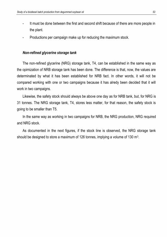
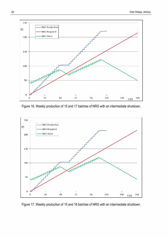
As documented in the next figures, if the stock line is observed, the NRG storage tank
should be designed to store a maximum of 126 tonnes, implying a volume of 130 m3.
54 Ortiz Peláez, Ainhoa
Figure 16. Weekly production of 15 and 17 batches of NRG with an intermediate shutdown.
Figure 17. Weekly production of 15 and 16 batches of NRG with an intermediate shutdown.
Study of a biodiesel batch production from degummed soybean oil 55
8. CONCLUSIONS
The transesterification stage in the process of obtaining biodiesel has been studied and
designed. Although, the overall production process is continuously, it has been shown that the
transesterification step can work per batches as long as the production volumes will be low.
Quantities in mass of the different raw materials needed to produce 30 thousand tonnes per
year of refined biodiesel, are shown in the overall mass balance of the process (Figure & Table
3).
Transesterification stage will consist mainly of two vessels and two settlers, with the
necessary pumps, valves and pipes have been chosen, as well as the automation and control
system that is presented in the corresponding in the P&ID.
All the equipment was sized and specified with the exception of pumps and coalescer which
are designed by vendor.
Piping and Instrumentation Diagram (P&ID) as well as the block and process diagram were
drawn using AutoCad software.
Working in two campaigns with overlapping, batch time and cycle time have been
determined. In this case, the batch time is 7.5 (BT = 7.5 h) and the cycle time is 3 hours (CT =
3h).
The most convenient has been the weekly production of 31 or 32 batches, in two campaigns
of 15 and 16 batches, the first one, and 15 and 17 batches, the second one. In addition, even if
the purification stage and the recovery methanol excess operates continuously without
disruption, the transesterification stage will work only 5 days per week, with 3 shifts per day,
without working the weekends.
Working with two campaigns per week, necessarily involves an intermediate shutdown,
which it will be used for cleaning work and maintenance. Moreover, this shutdown has been
programmed in such a way that it takes place coinciding with the central shift of the plant.

56 Ortiz Peláez, Ainhoa
Study of a biodiesel batch production from degummed soybean oil 57
REFERENCES AND NOTES 1. Environmental and Energy Study Institute (EESI). Bioenergy (Biofuels and Biomass). [Online]
October 5th 2015. www.eesi.org. (February 2017) 2. Biofuels. The fuel of the future. Biofuels: What are they? [Online] August 31st 2012.
www.biofuel.org.uk. (February 2017) 3. Biofuels Guide. Biofuel: A short Review. [Online] February 17th 2008. www.biofuelguide.net (March
2017) 4. Erickson, D. [Ed.], Practical handbook of soybean processing and utilization. 1st Champaign: s.n. 1995 (March 2017) 5. Knothe G., Krahl J. and Gerpen J. Biodiesel handbook. 2nd. 2010. (March 2017) 6. Prentice Hall [Ed.]. Biegler, L.T., Grossmann, I.E., Westerberg, A.W. Systematic methods of chemical
process design. 1997. (February 2017) 7. Medica panamericana [Ed.], 5th edition. Atkins Jones. Principios de Química. 2012. Capítulo 19
(Química orgánica II: Polímeros y compuestos biológicos). (February 2017) 8. Universidad Nacional de Colombia. Tesis doctoral. Evaluación experimental de la producción de
Biodiesel por destilación reactiva. [Online] April 2010. www.bdigital.unal.edu.com (March 2017) 9. Camino, M. et at. INTECH. An overview of Enzyme-Catalyzed Reactions and alternative Feedstock for
Biodiesel Production. [Online]. August 9th 2011. www.interchopen.com (March 2017) 10. Izquierdo Guerrero, Blanca. Treball final de màster. Development of a front-end engineering design
(feed) package for a biodiesel manufacturing plant from soybean oil. January 2017. (February 2017) 11. Noureddini, H and Zhu, D., Lincoln: AOCS Press. Kinetics of transesterification of soybean oil. 1997,
JAOCS, Vol. 74. (April 2017) 12. Massó, Y. El aislamiento térmico en el nuevo RITE. [On-line]. January 23th 2008. www.andimat.es.
(April 2017) 13. S. Esplugas y Mª E. Chamarro. Fundamentos de Transmisión de Calor. Título IV. Colección: Textos
docentes (Universidad d Barcelona). 305. (2005). (April 2017) 14. Tubular Exchanger Manufacturers Association (TEMA). [On-line]. www.tema.org (May 2017) 15. McGraw Hill [Ed.], 8th edition. Donald W. Green and Robert H. Perry. Perry’s Chemical Engineers
Handbook. Chapter 11: Heat-Transfer Equipment. 1999. (May 2017) 16. Roffel, Brian; Betlem, Ben. Process dynamics and control: modelling for control and prediction.
Chichester: Wiley, cop. 2006. (May 2017) 17. Castle pumps. [On-line]. www.castlepumps.cm (June 2017) 18. Purcell, J.E. New Jersey: s.n Proceedings of the 14th international pump users. A comparison of
positive displacement and centrifugal pump applications. (June 2017) 19. Méndez, C.A., Cerdá, J., Grossmann, I.E., Harjunkoski, I., Fahl. M. State of the art review of
optimization methods for short-term scheduling of batch plants. Computers & Chemical Engineering, 5, 2006. (May 2017)
20. Gobierno de España. Ministerio de Empleo y Seguridad Laboral. Fichas Internacionales de Seguridad Química. [On-line] 2016. www.insht.es. (February 2017)

58 Ortiz Peláez, Ainhoa
Study of a biodiesel batch production from degummed soybean oil 59
ACRONYMS
µ Absolute (Dynamic) viscosity [kg·m-1·s-1]
ºC Celsius
ºF Faraday
λ Latent heat [J/kg]
σLE Yield strength [Pa]
ΔP Pressure drop [Pa]
ΔT Temperature difference [K]
ΔTml Average temperature logarithmic [K]
ρ Weight density of fluid [kg/m3]
A Area [m2]
BT Batch time
BS Batch size
BTU British thermal unit
CT Cycle time [h]
Cp Calorific capacity [J/(kg·k)]
DG Diglyceride
DSO Degummed soybean oil
dext External diameter [m]
dint Internal diameter [m]
D diameter [m]
e Thickness [m]
60 Ortiz Peláez, Ainhoa
E-01 Heat-Exchanger
FFA Free Fatty Acids
FIS Finite Intermediate Storage
ft feet
gal Gallon
GHG Green – House Gas
h height [m]
HDV Charge and discharge valve
lb Pounds
L Length [m]
LT Level Transmit
LI Level Indicate
MG Monoglyceride
ME Methyl ester
MeOH Methanol
MSn Make span [h]
NEB Net Energy Balance
Np Power’s number
N Turn speed [rpm]
NSPH Net Positive Suction Heat
NRB Non-Refined Biodiesel
OTi Equipment operating time
P Power [W]
P Equipment Pump
P&ID Piping and Instrumentation Diagram
PT Pressure Transmit
PI Pressure Indicate
PSV Pressure Switch Valve
Study of a biodiesel batch production from degummed soybean oil 61
Q Exchanged heat [W]
Re Reynold’s number [dimensionless]
R Radius [m]
RT Rotation Transmit
RB Refined Biodiesel
SM Sodium methoxide
S Section [m2]
S-01 First settler
S-02 Second settler
TG Triglyceride
TEMA Tubular Exchanger Manufacturers Association
TDH Total Dynamic Head
t tonne
t’ absolute time [s]
T Temperature [ºC]
TT Temperature Transmit
TI Temperature Indicate
T1 Soybean oil storage process tank
T2 Methanol storage process tank
T3 Sodium methoxide 2% storage process tank
T4 Non-refined glycerine storage tank
T5 Non-refined biodiesel storage tank
U Heat Transfer Coefficient [W/(m2·K)]
V Volume [m3]
V-01 First vessel
V-02 Second vessel
W Watts [J/s]

62 Ortiz Peláez, Ainhoa
WT Weight Transmit
WI Wight Indicate
y year
ZW Zero Wait
Study of a biodiesel batch production from degummed soybean oil 63
TABLE AND FIGURES LISTS AND DIAGRAMS
Table lists
Table 1. Bioethanol and Biodiesel comparison.
Table 2. Soybean oil’s composition.
Table 3. Annual global mass balance.
Table 4. Mass balance by batch.
Table 5. Characteristics of vessel V-01.
Table 6. Agitation system characteristics.
Table 7. Jacketed vessels characteristics.
Table 8. Settlers characteristics.
Table 9. Settlers height.
Table 10. Characteristics of shell-and-tube exchanger.
Table 11. Pipe dimensioning.
Table 12. Storage tanks dimensions.
Table 13. Transesterification P&ID.
Table 14. Roadmap for scheduling in transesterification stage.
Table 15. Stages time.
Table 16. Occupation time of equipments.
Table 17. Effective non-effective process time in one campaign.
Table 18. Effective and non-effective process time in two campaigns.
Table 19. Vessel contents.
64 Ortiz Peláez, Ainhoa
Table 20. Specifications of both vessels.
Table 21. Agitation’s parameters depending of the regime.
Table 22. Characteristics of agitation system.
Table 23. Jacketed characteristics.
Table 24. Contained of both settlers.
Table 25. Specifications of both settlers.
Table 26. Settlers height.
Table 27. Characteristics of shell-and-tube exchanger.
Table 28. First pipe dimensioning.
Table 29. Pipe dimensioning.
Table 30. V-01 specifications sheet.
Table 31. V-02 specifications sheet.
Table 32. S-01 specifications sheet.
Table 33. S-02 specifications sheet.
Table 34. E-01 specifications sheet.
Figure lists
Figure 1. Biodiesel production by soybean oil.
Figure 2. Transesterification reaction.
Figure 3. Overall diagram of the inputs and outputs of Biodiesel production.
Figure 4. Conversion vs reaction time.
Figure 5. Settler inputs and outputs.
Figure 6. Mass variation in T4 per batch due to production.
Figure 7. Mass variation in T5 per batch due to production.
Figure 8. BEM Heat Exchanger with one step.
Figure 9. Batch time.
Study of a biodiesel batch production from degummed soybean oil 65
Figure 10. Production in non-overlapping campaign.
Figure 11. Production in overlapping campaign.
Figure 12. 32 batches per week of NRB.
Figure 13. 31 batches per week of NRB.
Figure 14. Weekly production of 15 and 17 batches of NRB with an intermediate shutdown.
Figure 15. Weekly production of 15 and 16 batches of NRB with an intermediate shutdown.
Figure 16. Weekly production of 15 and 17 batches of NRG with an intermediate shutdown.
Figure 17. Weekly production of 15 and 16 batches of NRG with an intermediate shutdown.
Figure 18. Settlers volume.
Figure 19. Typical overal heat-transfer coefficient in tubular heat exchangers.
Diagrams
Block flow diagram
Process flow diagram
Control recipe
P&ID

66 Ortiz Peláez, Ainhoa

Study of a biodiesel batch production from degummed soybean oil 67
APPENDICES

Study of a biodiesel batch production from degummed soybean oil 69
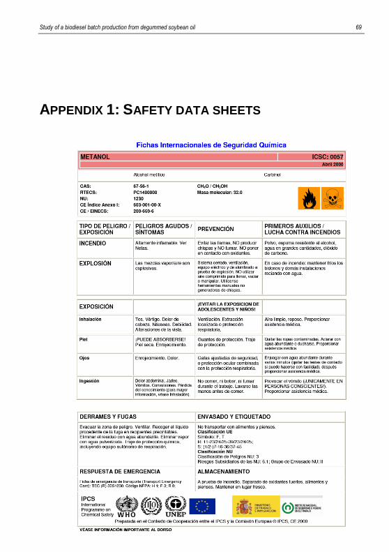
APPENDIX 1: SAFETY DATA SHEETS
70 Ortiz Peláez, Ainhoa
Study of a biodiesel batch production from degummed soybean oil 71
72 Ortiz Peláez, Ainhoa
Study of a biodiesel batch production from degummed soybean oil 73
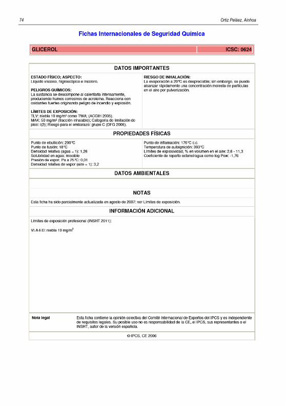
74 Ortiz Peláez, Ainhoa
Study of a biodiesel batch production from degummed soybean oil 75
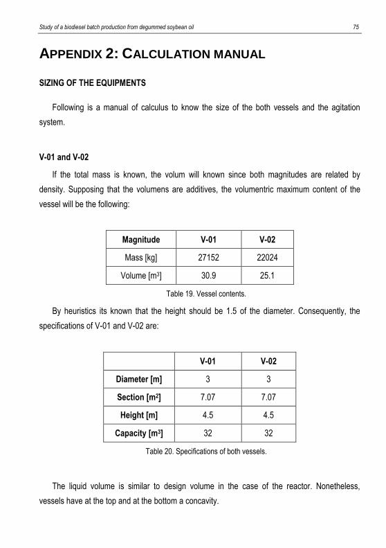
APPENDIX 2: CALCULATION MANUAL SIZING OF THE EQUIPMENTS
Following is a manual of calculus to know the size of the both vessels and the agitation
system.
V-01 and V-02
If the total mass is known, the volum will known since both magnitudes are related by
density. Supposing that the volumens are additives, the volumentric maximum content of the
vessel will be the following:
Magnitude V-01 V-02
Mass [kg] 27152 22024
Volume [m3] 30.9 25.1
Table 19. Vessel contents.
By heuristics its known that the height should be 1.5 of the diameter. Consequently, the
specifications of V-01 and V-02 are:
V-01 V-02
Diameter [m] 3 3
Section [m2] 7.07 7.07
Height [m] 4.5 4.5
Capacity [m3] 32 32
Table 20. Specifications of both vessels.
The liquid volume is similar to design volume in the case of the reactor. Nonetheless,
vessels have at the top and at the bottom a concavity.
76 Ortiz Peláez, Ainhoa
This concavity will be free volume which is considered as the excess that the volume must
have for safety. Furthermore, It has been decided that both reactors have the same dimensions
because it comes out cheaper than if they had different dimensions.
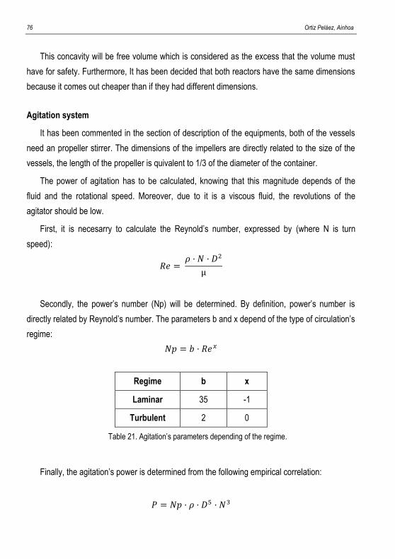
Agitation system
It has been commented in the section of description of the equipments, both of the vessels
need an propeller stirrer. The dimensions of the impellers are directly related to the size of the
vessels, the length of the propeller is quivalent to 1/3 of the diameter of the container.
The power of agitation has to be calculated, knowing that this magnitude depends of the
fluid and the rotational speed. Moreover, due to it is a viscous fluid, the revolutions of the
agitator should be low.
First, it is necesarry to calculate the Reynold’s number, expressed by (where N is turn
speed):
𝑅𝑒 = 𝜌 · 𝑁 · 𝐷2
µ
Secondly, the power’s number (Np) will be determined. By definition, power’s number is
directly related by Reynold’s number. The parameters b and x depend of the type of circulation’s
regime:
𝑁𝑝 = 𝑏 · 𝑅𝑒𝑥
Regime b x
Laminar 35 -1
Turbulent 2 0
Table 21. Agitation’s parameters depending of the regime.
Finally, the agitation’s power is determined from the following empirical correlation:
𝑃 = 𝑁𝑝 · 𝜌 · 𝐷5 · 𝑁3
Study of a biodiesel batch production from degummed soybean oil 77
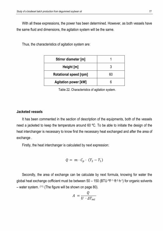
With all these expressions, the power has been determined. However, as both vessels have
the same fluid and dimensions, the agitation system will be the same.
Thus, the characteristics of agitation system are:
Stirrer diameter [m] 1
Height [m] 3
Rotational speed [rpm] 60
Agitation power [kW] 6
Table 22. Characteristics of agitation system.
Jacketed vessels
It has been commented in the section of description of the equipments, both of the vessels
need a jacketed to keep the temperature around 60 ºC. To be able to initiate the design of the
heat interchanger is necessary to know first the necessary heat exchanged and after the area of
exchange .
Firstly, the heat interchanger is calculated by next expression:
𝑄 = 𝑚 · 𝐶𝑝 · (𝑇2 − 𝑇1)
Secondly, the area of exchange can be calculate by next formula, knowing for water the
global heat exchange cofficient must be between 50 – 150 (BTU·ºF-1·ft-2·h-1) for organic solvents
– water system. (11) (The figure will be shown on page 80).
𝐴 =𝑄
𝑈 · 𝛥𝑇𝑚𝑙
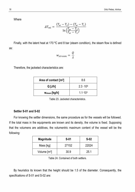
78 Ortiz Peláez, Ainhoa
Where
𝛥𝑇𝑚𝑙 = (𝑇𝑤 − 𝑇2) − (𝑇𝑤 − 𝑇1)
ln (𝑇𝑤 − 𝑇2
𝑇𝑤 − 𝑇1)
Finally, with the latent heat at 170 ºC and 8 bar (steam condition), the steam flow is defined
as:
𝑤𝑠𝑡𝑟𝑒𝑎𝑚 = 𝑄
𝜆
Therefore, the jacketed characteristics are:
Area of contact [m2] 8.6
Q [J/h] 2.3 ·109
wsteam [kg/h] 1.1·103
Table 23. Jacketed characteristics.
Settler S-01 and S-02
For knowing the settler dimensions, the same procedure as for the vessels will be followed.
If the total mass in the equipments are known and its density, the volume is fixed. Supposing
that the volumens are additives, the volumentric maximum content of the vessel will be the
following:
Magnitude S-01 S-02
Mass [kg] 27152 22024
Volume [m3] 30.9 25.1
Table 24. Contained of both settlers.
By heuristics its known that the height should be 1.5 of the diameter. Consequently, the
specifications of S-01 and S-02 are:
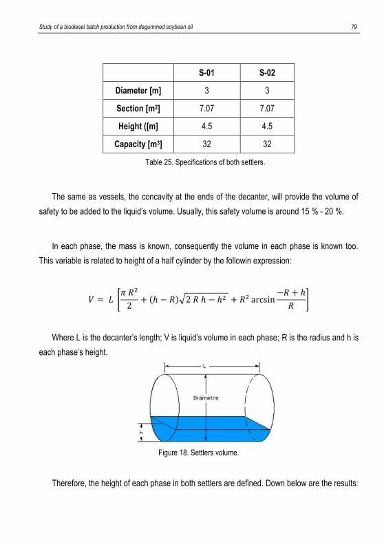
Study of a biodiesel batch production from degummed soybean oil 79
S-01 S-02
Diameter [m] 3 3
Section [m2] 7.07 7.07
Height ([m] 4.5 4.5
Capacity [m3] 32 32
Table 25. Specifications of both settlers.
The same as vessels, the concavity at the ends of the decanter, will provide the volume of
safety to be added to the liquid’s volume. Usually, this safety volume is around 15 % - 20 %.
In each phase, the mass is known, consequently the volume in each phase is known too.
This variable is related to height of a half cylinder by the followin expression:
𝑉 = 𝐿 [𝜋 𝑅2
2+ (ℎ − 𝑅)√2 𝑅 ℎ − ℎ2 + 𝑅2 arcsin
−𝑅 + ℎ
𝑅]
Where L is the decanter’s length; V is liquid’s volume in each phase; R is the radius and h is
each phase’s height.
Figure 18. Settlers volume.
Therefore, the height of each phase in both settlers are defined. Down below are the results:
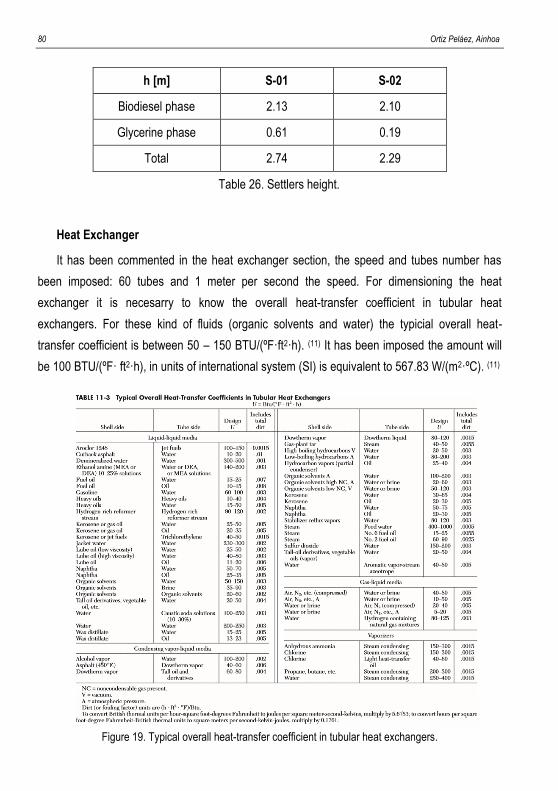
80 Ortiz Peláez, Ainhoa
h [m] S-01 S-02
Biodiesel phase 2.13 2.10
Glycerine phase 0.61 0.19
Total 2.74 2.29
Table 26. Settlers height.
Heat Exchanger
It has been commented in the heat exchanger section, the speed and tubes number has
been imposed: 60 tubes and 1 meter per second the speed. For dimensioning the heat
exchanger it is necesarry to know the overall heat-transfer coefficient in tubular heat
exchangers. For these kind of fluids (organic solvents and water) the typicial overall heat-
transfer coefficient is between 50 – 150 BTU/(ºF·ft2·h). (11) It has been imposed the amount will
be 100 BTU/(ºF· ft2·h), in units of international system (SI) is equivalent to 567.83 W/(m2·ºC). (11)
Figure 19. Typical overall heat-transfer coefficient in tubular heat exchangers.
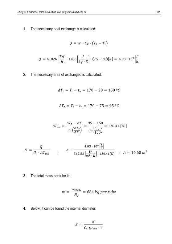
Study of a biodiesel batch production from degummed soybean oil 81
1. The necessary heat exchange is calculated:
𝑄 = 𝑤 · 𝐶𝑃 · (𝑇2 − 𝑇1)
𝑄 = 41026 [𝑘𝑔
ℎ] · 1786 [
𝐽
𝑘𝑔 · 𝐾] · (75 − 20)[𝐾] = 4.03 · 109 [
𝐽
ℎ]
2. The necessary area of exchanged is calculated:
𝛥𝑇1 = 𝑇𝑠 − 𝑡𝑒 = 170 − 20 = 150 º𝐶
𝛥𝑇2 = 𝑇𝑒 − 𝑡𝑠 = 170 − 75 = 95 º𝐶
; ; 𝐴 = 14.60 𝑚2
3. The total mass per tube is:
𝑤 = 𝑤𝑡𝑜𝑡𝑎𝑙
𝑁𝑇
= 684 𝑘𝑔 𝑝𝑒𝑟 𝑡𝑢𝑏𝑒
4. Below, it can be found the internal diameter:
𝑆 = 𝑤
𝜌𝑡𝑟𝑖𝑜𝑙𝑒𝑖𝑛 · 𝑣
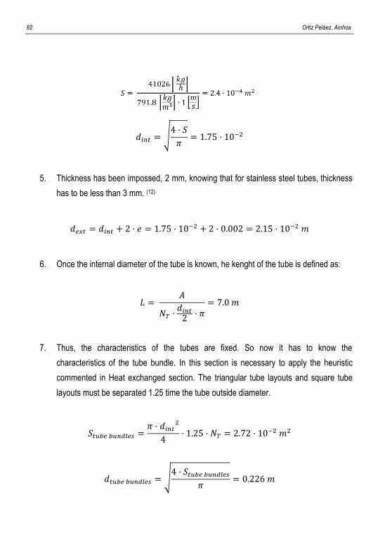
82 Ortiz Peláez, Ainhoa
𝑑𝑖𝑛𝑡 = √4 · 𝑆
𝜋= 1.75 · 10−2
5. Thickness has been impossed, 2 mm, knowing that for stainless steel tubes, thickness
has to be less than 3 mm. (12)
𝑑𝑒𝑥𝑡 = 𝑑𝑖𝑛𝑡 + 2 · 𝑒 = 1.75 · 10−2 + 2 · 0.002 = 2.15 · 10−2 𝑚
6. Once the internal diameter of the tube is known, he kenght of the tube is defined as:
𝐿 = 𝐴
𝑁𝑇 ·𝑑𝑖𝑛𝑡
2· 𝜋
= 7.0 𝑚
7. Thus, the characteristics of the tubes are fixed. So now it has to know the
characteristics of the tube bundle. In this section is necessary to apply the heuristic
commented in Heat exchanged section. The triangular tube layouts and square tube
layouts must be separated 1.25 time the tube outside diameter.
𝑆𝑡𝑢𝑏𝑒 𝑏𝑢𝑛𝑑𝑙𝑒𝑠 =𝜋 · 𝑑𝑖𝑛𝑡
2
4· 1.25 · 𝑁𝑇 = 2.72 · 10−2 𝑚2
𝑑𝑡𝑢𝑏𝑒 𝑏𝑢𝑛𝑑𝑙𝑒𝑠 = √4 · 𝑆𝑡𝑢𝑏𝑒 𝑏𝑢𝑛𝑑𝑙𝑒𝑠
𝜋= 0.226 𝑚
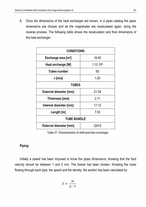
Study of a biodiesel batch production from degummed soybean oil 83
8. Once the dimensions of the heat exchanger are known, in a pipes catalog the pipes
dimensions are chosen and all the magnitudes are recalculated again, doing the
reverse process. The following table shows the recalculation and final dimensions of
the heat exchanger.
CONDITIONS
Exchange area [m2] 16.40
Heat exchange [W] 1.12·106
Tubes number 60
v [m/s] 1.00
TUBES
External diameter [mm] 21.34
Thickness [mm] 2.11
Internal diameter [mm] 17.12
Length [m] 7.00
TUBE BUNDLE
External diameter [mm] 224.8
Table 27. Characteristics of shell-and-tube exchanger.
Piping
Initially a speed has been imposed to know the pipes dimensions, knowing that the fluid
velocity should be between 1 and 2 m/s. The lowest has been chosen. Knowing the mass
flowing through each pipe, the speed and the density, the section has been calculated by:
𝑆 = 𝑤
𝜌 · 𝑣
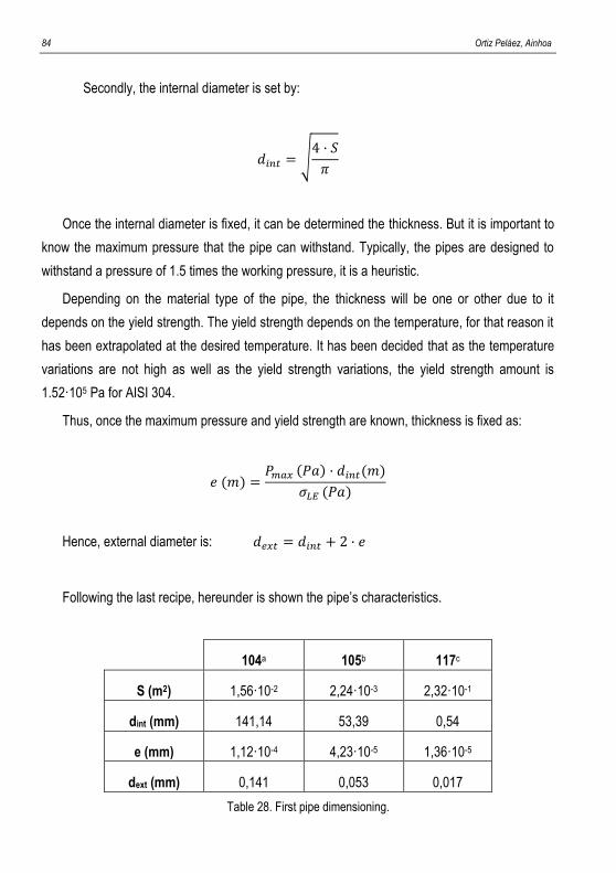
84 Ortiz Peláez, Ainhoa
Secondly, the internal diameter is set by:
𝑑𝑖𝑛𝑡 = √4 · 𝑆
𝜋
Once the internal diameter is fixed, it can be determined the thickness. But it is important to
know the maximum pressure that the pipe can withstand. Typically, the pipes are designed to
withstand a pressure of 1.5 times the working pressure, it is a heuristic.
Depending on the material type of the pipe, the thickness will be one or other due to it
depends on the yield strength. The yield strength depends on the temperature, for that reason it
has been extrapolated at the desired temperature. It has been decided that as the temperature
variations are not high as well as the yield strength variations, the yield strength amount is
1.52·105 Pa for AISI 304.
Thus, once the maximum pressure and yield strength are known, thickness is fixed as:
𝑒 (𝑚) =𝑃𝑚𝑎𝑥 (𝑃𝑎) · 𝑑𝑖𝑛𝑡(𝑚)
𝜎𝐿𝐸 (𝑃𝑎)
Hence, external diameter is: 𝑑𝑒𝑥𝑡 = 𝑑𝑖𝑛𝑡 + 2 · 𝑒
Following the last recipe, hereunder is shown the pipe’s characteristics.
104a 105b 117c
S (m2) 1,56·10-2 2,24·10-3 2,32·10-1
dint (mm) 141,14 53,39 0,54
e (mm) 1,12·10-4 4,23·10-5 1,36·10-5
dext (mm) 0,141 0,053 0,017
Table 28. First pipe dimensioning.
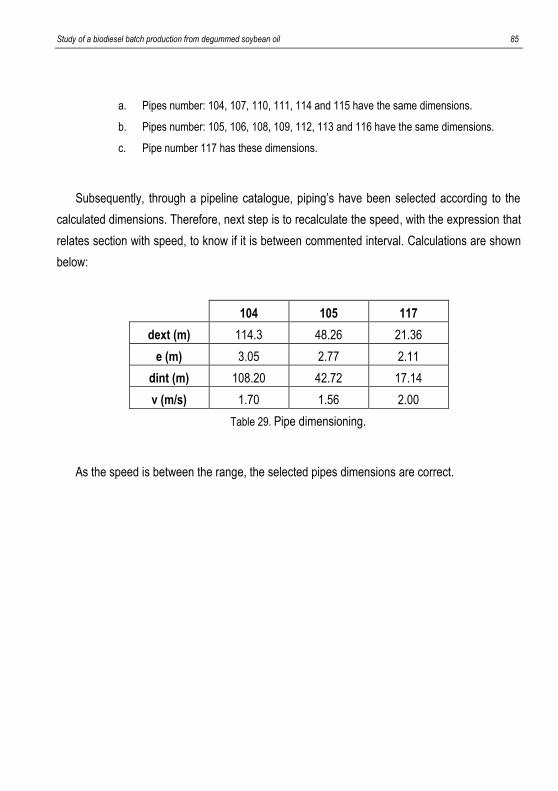
Study of a biodiesel batch production from degummed soybean oil 85
a. Pipes number: 104, 107, 110, 111, 114 and 115 have the same dimensions.
b. Pipes number: 105, 106, 108, 109, 112, 113 and 116 have the same dimensions.
c. Pipe number 117 has these dimensions.
Subsequently, through a pipeline catalogue, piping’s have been selected according to the
calculated dimensions. Therefore, next step is to recalculate the speed, with the expression that
relates section with speed, to know if it is between commented interval. Calculations are shown
below:
104 105 117
dext (m) 114.3 48.26 21.36
e (m) 3.05 2.77 2.11
dint (m) 108.20 42.72 17.14
v (m/s) 1.70 1.56 2.00
Table 29. Pipe dimensioning.
As the speed is between the range, the selected pipes dimensions are correct.

86 Ortiz Peláez, Ainhoa
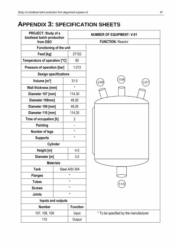
Study of a biodiesel batch production from degummed soybean oil 87
APPENDIX 3: SPECIFICATION SHEETS
PROJECT: Study of a biodiesel batch production
from DSO
NUMBER OF EQUIPMENT: V-01
FUNCTION: Reactor
Functioning of the unit
Feed [kg] 27152
Temperature of operation [°C] 60
Pressure of operation [bar] 1.013
Design specifications
Volume [m3] 31.5
Wall thickness [mm] *
Diameter 107 [mm] 114.30
Diameter 108mm] 48.26
Diameter 109 [mm] 48.26
Diameter 110 [mm] 114.30
Time of occupation [h] 2
Painting -
Number of legs *
Supports *
Cylinder
Height [m] 4.5
Diameter [m] 3.0
Materials
Tank Steel AISI 304
Flanges *
Tubes *
Screws *
Joints *
Inputs and outputs
Number Function
107, 108, 109 Input * To be specified by the manufacturer
110 Output
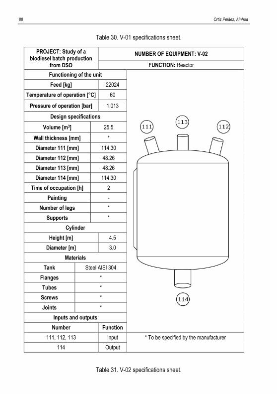
88 Ortiz Peláez, Ainhoa
Table 30. V-01 specifications sheet.
PROJECT: Study of a biodiesel batch production
from DSO
NUMBER OF EQUIPMENT: V-02
FUNCTION: Reactor
Functioning of the unit
Feed [kg] 22024
Temperature of operation [°C] 60
Pressure of operation [bar] 1.013
Design specifications
Volume [m3] 25.5
Wall thickness [mm] *
Diameter 111 [mm] 114.30
Diameter 112 [mm] 48.26
Diameter 113 [mm] 48.26
Diameter 114 [mm] 114.30
Time of occupation [h] 2
Painting -
Number of legs *
Supports *
Cylinder
Height [m] 4.5
Diameter [m] 3.0
Materials
Tank Steel AISI 304
Flanges *
Tubes *
Screws *
Joints *
Inputs and outputs
Number Function
111, 112, 113 Input * To be specified by the manufacturer
114 Output
Table 31. V-02 specifications sheet.
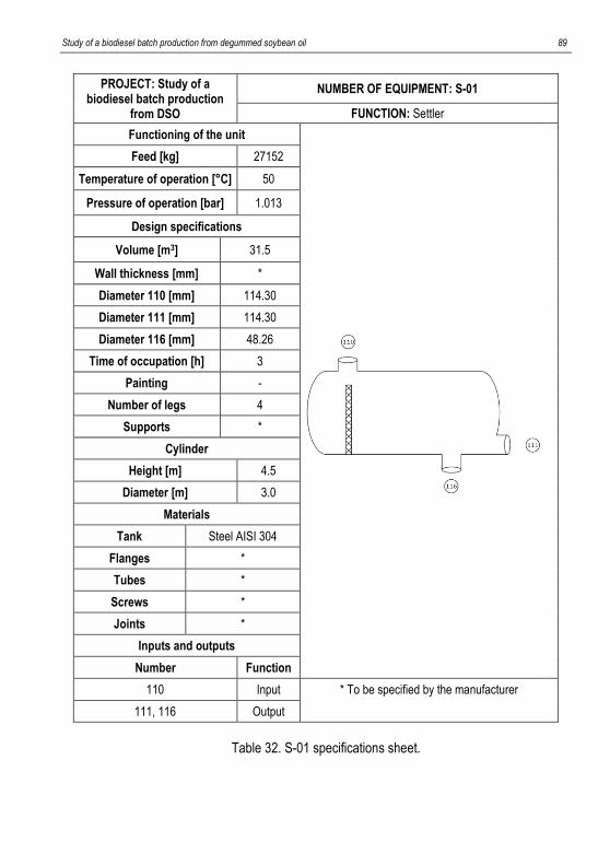
Study of a biodiesel batch production from degummed soybean oil 89
PROJECT: Study of a biodiesel batch production
from DSO
NUMBER OF EQUIPMENT: S-01
FUNCTION: Settler
Functioning of the unit
Feed [kg] 27152
Temperature of operation [°C] 50
Pressure of operation [bar] 1.013
Design specifications
Volume [m3] 31.5
Wall thickness [mm] *
Diameter 110 [mm] 114.30
Diameter 111 [mm] 114.30
Diameter 116 [mm] 48.26
Time of occupation [h] 3
Painting -
Number of legs 4
Supports *
Cylinder
Height [m] 4.5
Diameter [m] 3.0
Materials
Tank Steel AISI 304
Flanges *
Tubes *
Screws *
Joints *
Inputs and outputs
Number Function
110 Input * To be specified by the manufacturer
111, 116 Output
Table 32. S-01 specifications sheet.
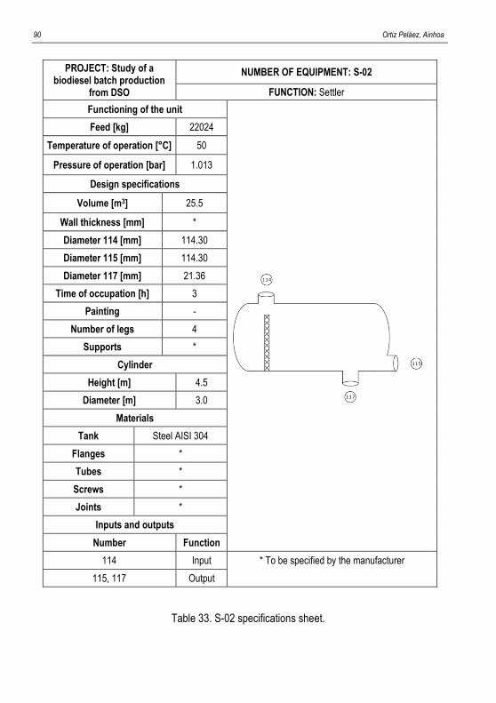
90 Ortiz Peláez, Ainhoa
PROJECT: Study of a
biodiesel batch production from DSO
NUMBER OF EQUIPMENT: S-02
FUNCTION: Settler
Functioning of the unit
Feed [kg] 22024
Temperature of operation [°C] 50
Pressure of operation [bar] 1.013
Design specifications
Volume [m3] 25.5
Wall thickness [mm] *
Diameter 114 [mm] 114.30
Diameter 115 [mm] 114.30
Diameter 117 [mm] 21.36
Time of occupation [h] 3
Painting -
Number of legs 4
Supports *
Cylinder
Height [m] 4.5
Diameter [m] 3.0
Materials
Tank Steel AISI 304
Flanges *
Tubes *
Screws *
Joints *
Inputs and outputs
Number Function
114 Input * To be specified by the manufacturer
115, 117 Output
Table 33. S-02 specifications sheet.
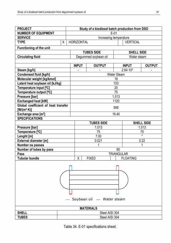
Study of a biodiesel batch production from degummed soybean oil 91
PROJECT Study of a biodiesel batch production from DSO
NUMBER OF EQUIPMENT E-01
SERVICE Increasing temperature
TYPE X HORIZONTAL VERTICAL
Functioning of the unit
TUBES SIDE SHELL SIDE
Circulating fluid Degummed soybean oil Water steam
INPUT OUTPUT INPUT OUTPUT
Steam [kg/h] - - 2.64·104 -
Condensed fluid [kg/h] Water Steam
Molecular weight [kg/kmol] 18
Latent heat soybean oil [kJ/kg] 153
Temperature input [ºC] 20
Temperature output [ºC] 75
Pressure [bar] 1.013
Exchanged heat [kW] 1120
Global coefficient of heat transfer [W/(m2·K)]
568
Exchange area [m2] 16.40
SPECIFICATIONS
TUBES SIDE SHELL SIDE
Pressure [bar] 1.013 1.013
Temperature [ºC] 75 75
Lenght [m] 7.00 *
External diameter [m] 0.021 0.22
Number os passes 1 1
Number of tubes by pass 60
Pass TRIANGULAR
Tubular bundle X FIXED FLOATING
MATERIALS
SHELL Steel AISI 304
TUBES Steel AISI 304
Table 34. E-01 specifications sheet.