Embed Size (px)
Citation preview
15/04/2014
1
Power Transformers
Prof Peter Crossley
Ferranti Building, C14
School of Electrical and Electronic Engineering
01613064803(office)
EEEN60301 Power System Modelling
Power Transformers
Monday 23rd October 2013
1
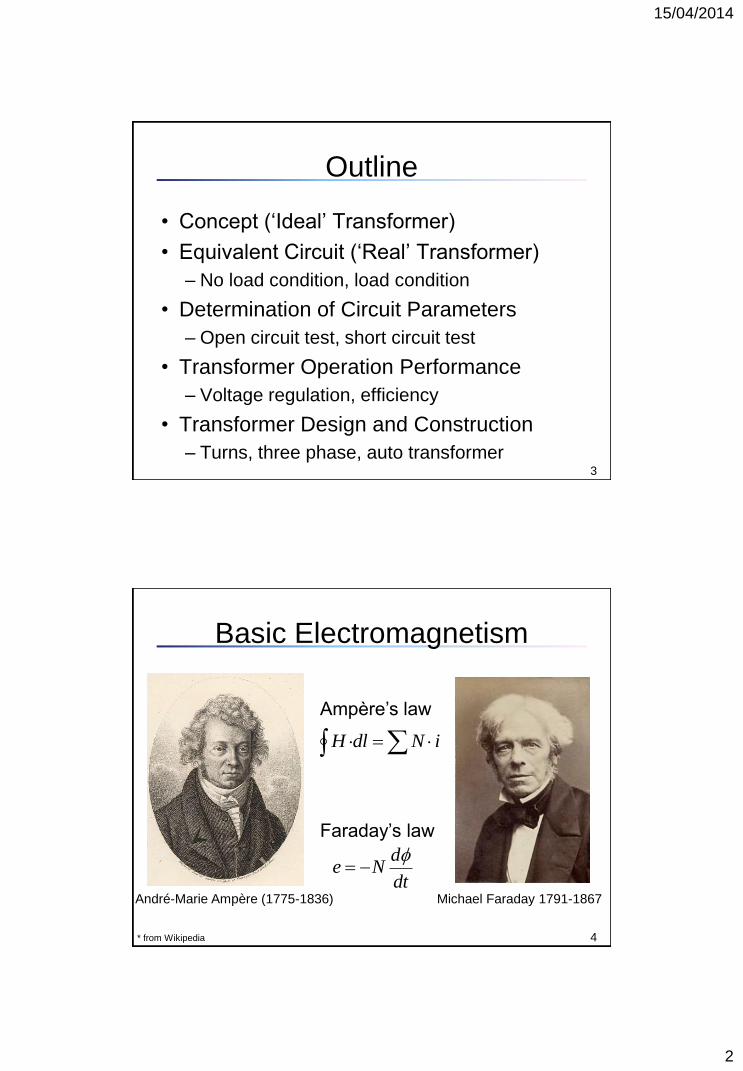
Transformers in Power Systems
400 kV Power transformer, *from ALSTOM Grid
2
400 kV transformer core and winding,
*from Electrical Engineering Portal
400 kV transformer end insulation, *from
CIGRE brochure 323
15/04/2014
2
Outline
• Concept (‘Ideal’ Transformer)
• Equivalent Circuit (‘Real’ Transformer)
– No load condition, load condition
• Determination of Circuit Parameters
– Open circuit test, short circuit test
• Transformer Operation Performance
– Voltage regulation, efficiency
• Transformer Design and Construction
– Turns, three phase, auto transformer 3
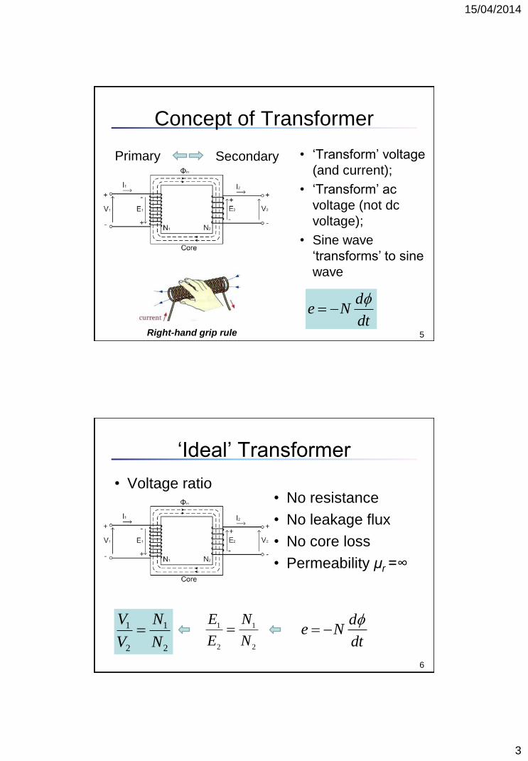
Basic Electromagnetism
André-Marie Ampère (1775-1836) Michael Faraday 1791-1867
* from Wikipedia
dt
dNe
iNdlH
Ampère’s law
Faraday’s law
4
15/04/2014
3
Concept of Transformer
• ‘Transform’ voltage
(and current);
• ‘Transform’ ac
voltage (not dc
voltage);
• Sine wave
‘transforms’ to sine
wave
Secondary Primary
Right-hand grip rule 5
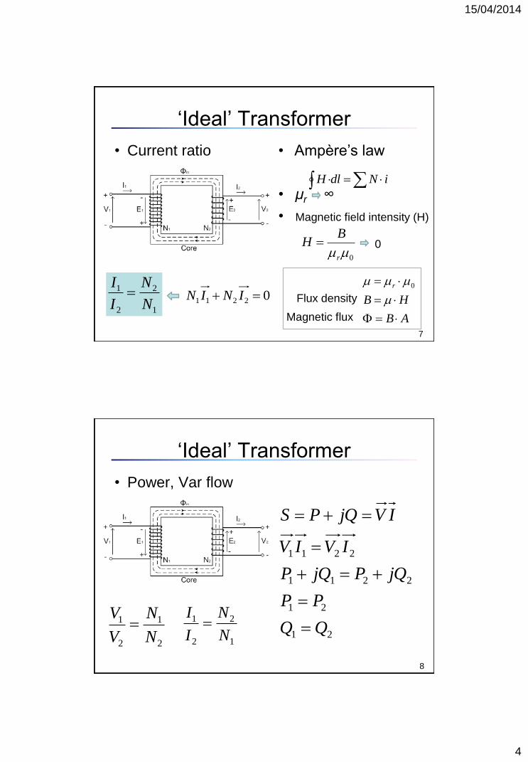
dt
dNe
‘Ideal’ Transformer
• Voltage ratio
2
1
2
1
N
N
E
E
• No resistance
• No leakage flux
• No core loss
• Permeability μr =∞
1 1
2 2
V N
V N
6
dt
dNe
15/04/2014
4
‘Ideal’ Transformer
• Ampère’s law
• μr ∞
• Magnetic field intensity (H)
• Current ratio
02211 ININ
0r
BH
iNdlH
1
2
2
1
N
N
I
I
AB
HB
r
0
Flux density
Magnetic flux
7
0
‘Ideal’ Transformer
• Power, Var flow
1 1
2 2
V N
V N
1
2
2
1
N
N
I
I
8
21
21
2211
2211
PP
jQPjQP
IVIV
IVjQPS
15/04/2014
5
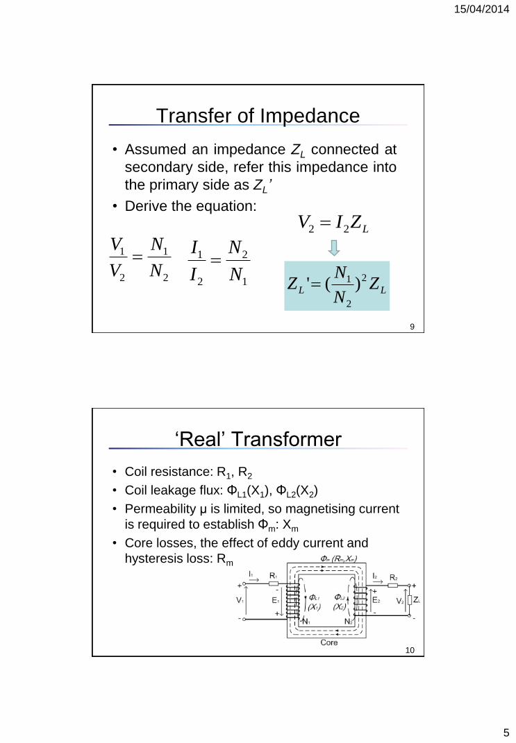
Transfer of Impedance
• Assumed an impedance ZL connected at
secondary side, refer this impedance into
the primary side as ZL’
• Derive the equation:
1 1
2 2
V N
V N 1 2
2 1
I N
I N
9
LZIV 22
LL ZN
NZ 2
2
1 )('
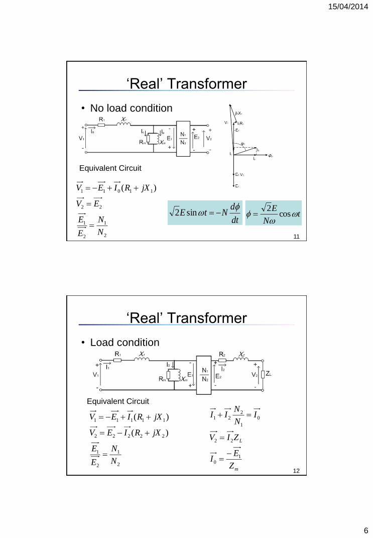
‘Real’ Transformer
• Coil resistance: R1, R2
• Coil leakage flux: ΦL1(X1), ΦL2(X2)
• Permeability μ is limited, so magnetising current
is required to establish Φm: Xm
• Core losses, the effect of eddy current and
hysteresis loss: Rm
10
15/04/2014
6
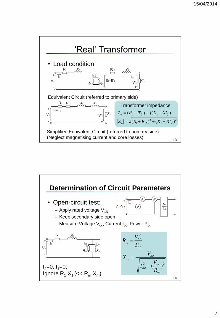
‘Real’ Transformer
• No load condition
11
Equivalent Circuit
tN
E
cos
2
dt
dNtE
sin2
2
1
2
1
22
11011 )(
N
N
E
E
EV
jXRIEV
‘Real’ Transformer
• Load condition
12 2
1
2
1
22222
11111
)(
)(
N
N
E
E
jXRIEV
jXRIEV
Equivalent Circuit
m
L
Z
EI
ZIV
IN
NII
10
22
0
1
221
15/04/2014
7
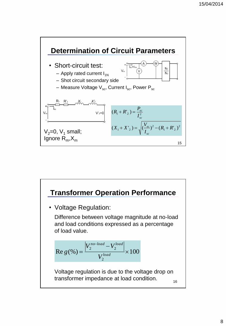
‘Real’ Transformer
• Load condition
13
Equivalent Circuit (referred to primary side)
Simplified Equivalent Circuit (referred to primary side)
(Neglect magnetising current and core losses)
2
21
2
21
2121
)'()'(
)'()'(
XXRRZ
XXjRRZ
w
w
Transformer impedance
Determination of Circuit Parameters
• Open-circuit test: – Apply rated voltage V1N
– Keep secondary side open
– Measure Voltage Voc, Current Ioc, Power Poc
14
I2=0, I1=0;
Ignore R1,X1 (<< Rm,Xm)
22
2
)(m
ococ
ocm
oc
ocm
R
VI
VX
P
VR
15/04/2014
8
Determination of Circuit Parameters
• Short-circuit test: – Apply rated current I1N
– Shot circuit secondary side
– Measure Voltage Vsc, Current Isc, Power Psc
15
2
21
2
21
221
)'()()'(
)'(
RRI
VXX
I
PRR
sc
sc
sc
sc
V2=0, V1 small;
Ignore Rm,Xm
Transformer Operation Performance
16
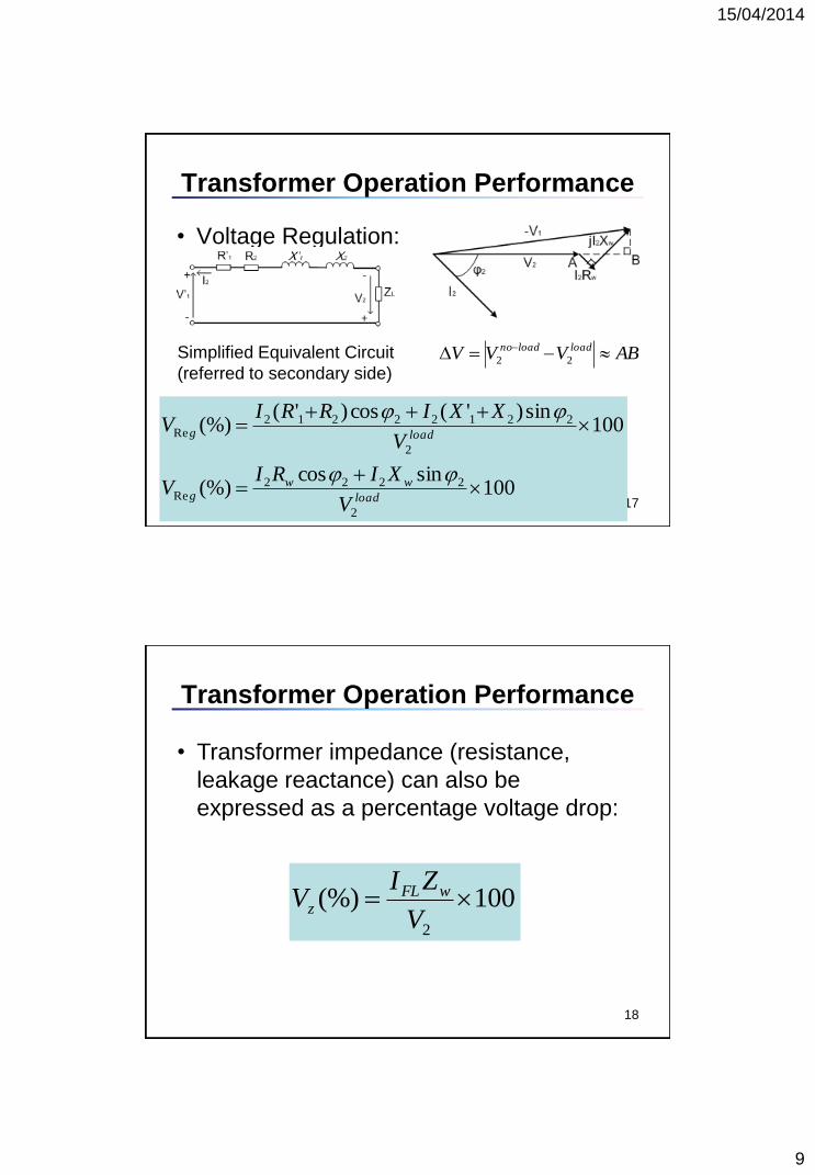
• Voltage Regulation:
Difference between voltage magnitude at no-load
and load conditions expressed as a percentage
of load value.
Voltage regulation is due to the voltage drop on
transformer impedance at load condition.
100(%)Re2
22
load
loadloadno
V
VVg
15/04/2014
9
Transformer Operation Performance
17
• Voltage Regulation:
Simplified Equivalent Circuit
(referred to secondary side)
100sincos
(%)
100sin)'(cos)'(
(%)
2
2222Re
2
22122212Re
load
wwg
loadg
V
XIRIV
V
XXIRRIV
ABVVV loadloadno
22
Transformer Operation Performance
18
• Transformer impedance (resistance,
leakage reactance) can also be
expressed as a percentage voltage drop:
100(%)2
V
ZIV wFL
z
15/04/2014
10
Transformer Operation Performance
19
Lossespower Output
power Output
power Input
power OutputEfficiency
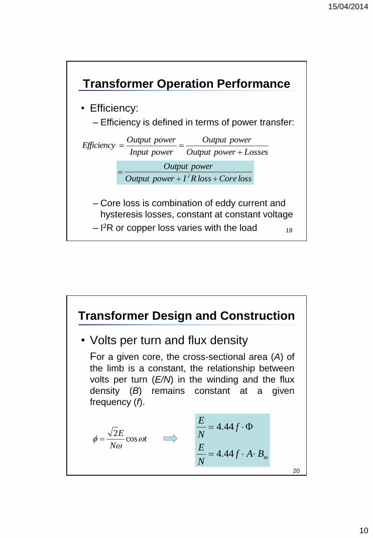
• Efficiency:
– Efficiency is defined in terms of power transfer:
– Core loss is combination of eddy current and
hysteresis losses, constant at constant voltage
– I2R or copper loss varies with the load
loss Coreloss RIpower Output
power Output2
Transformer Design and Construction
• Volts per turn and flux density
For a given core, the cross-sectional area (A) of
the limb is a constant, the relationship between
volts per turn (E/N) in the winding and the flux
density (B) remains constant at a given
frequency (f).
mBAfN
E
fN
E
44.4
44.4
20
tN
E
cos
2
15/04/2014
11
21
Transformer Design and Construction
• Exercise:
The maximum flux density within the magnetic
core of a 50 Hz, 400 kV/132 kV transformer is
restricted to 1.55 Tesla as the core has a circular
cross section with a diameter of 1 m. Calculate
the volts per turn for the winding and the number
of turns for HV and LV windings.
(This transformer is connected as Yyn*)
22
Transformer Design and Construction
kVE
2303
400
3
1
kVE
763
132
3
2
The phase voltage for HV winding is
The phase voltage for LV winding is
Volt per turn is calculated as
)(2705.055.15044.444.4 2 VAfBN
Em
The HV winding has N1=230000/270=851 turns
The LV winding has N2=76000/270=281.5 turns
• Solution:
15/04/2014
12
23
Transformer Design and Construction
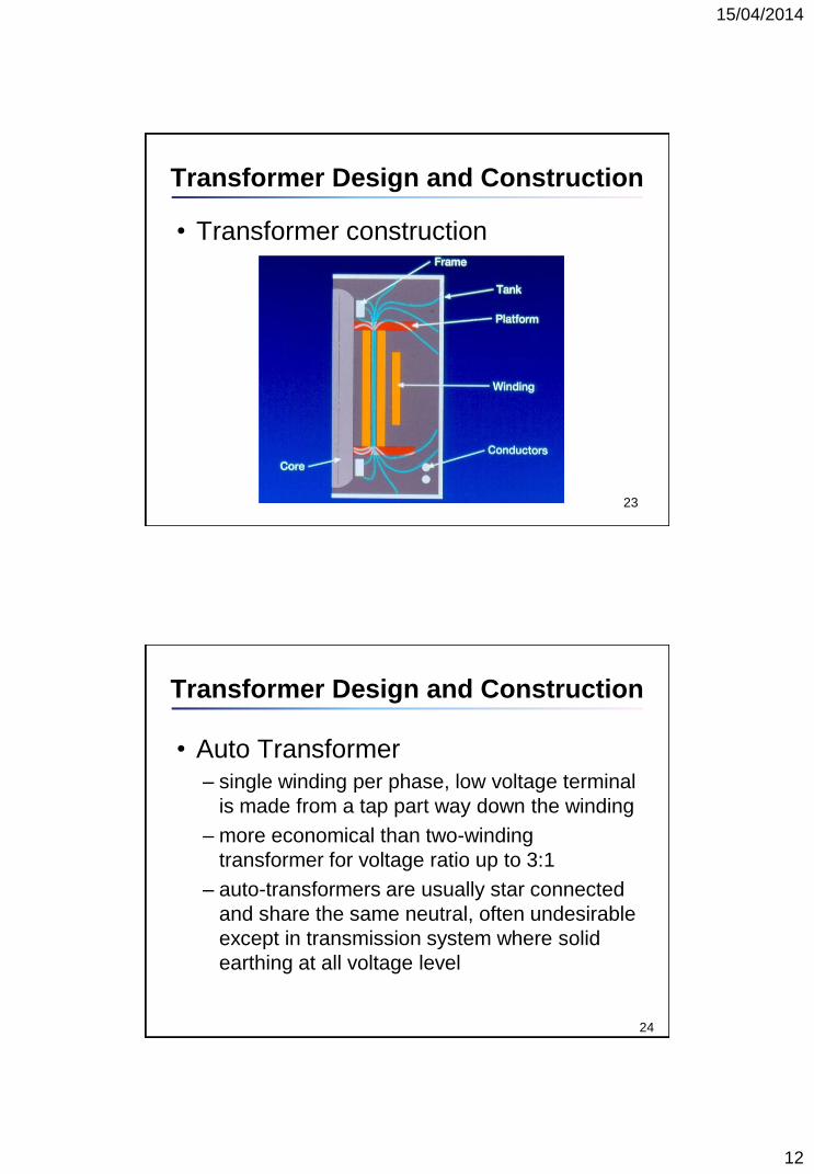
• Transformer construction
• Auto Transformer – single winding per phase, low voltage terminal
is made from a tap part way down the winding
– more economical than two-winding
transformer for voltage ratio up to 3:1
– auto-transformers are usually star connected
and share the same neutral, often undesirable
except in transmission system where solid
earthing at all voltage level
24
Transformer Design and Construction
15/04/2014
13
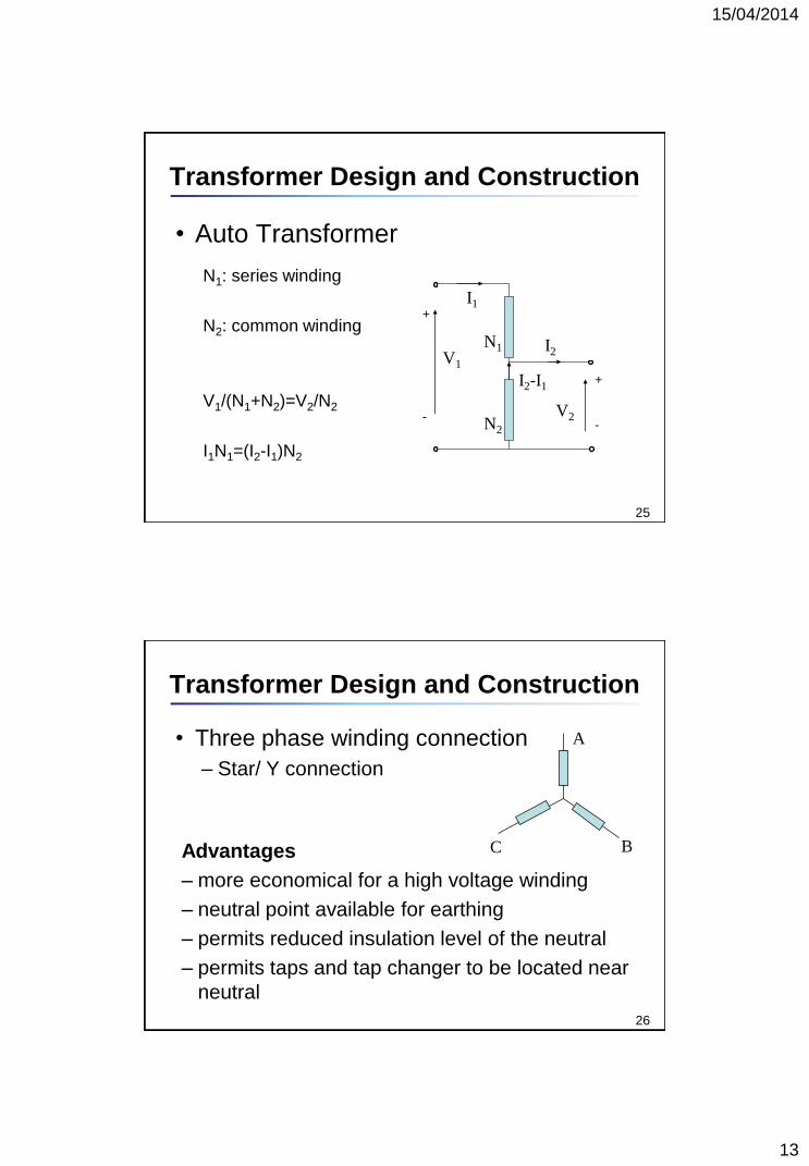
N1: series winding
N2: common winding
V1/(N1+N2)=V2/N2
I1N1=(I2-I1)N2
V1
V2
I1
I2
I2-I1
25
Transformer Design and Construction
• Auto Transformer
N1
N2
+
-
+
-
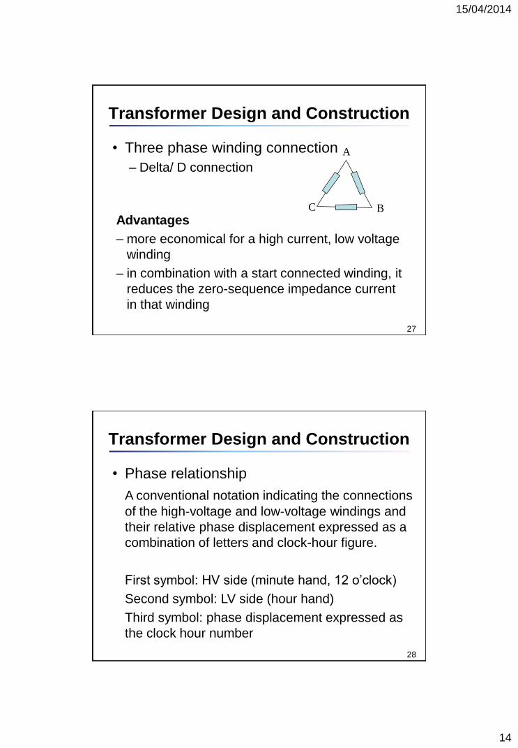
• Three phase winding connection
– Star/ Y connection
B
A
C
26
Transformer Design and Construction
Advantages
– more economical for a high voltage winding
– neutral point available for earthing
– permits reduced insulation level of the neutral
– permits taps and tap changer to be located near
neutral
15/04/2014
14
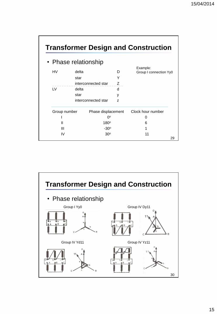
• Three phase winding connection
– Delta/ D connection
27
Transformer Design and Construction
Advantages
– more economical for a high current, low voltage
winding
– in combination with a start connected winding, it
reduces the zero-sequence impedance current
in that winding
A
C B
28
Transformer Design and Construction
• Phase relationship
A conventional notation indicating the connections
of the high-voltage and low-voltage windings and
their relative phase displacement expressed as a
combination of letters and clock-hour figure.
First symbol: HV side (minute hand, 12 o’clock)
Second symbol: LV side (hour hand)
Third symbol: phase displacement expressed as
the clock hour number
15/04/2014
15
29
Transformer Design and Construction
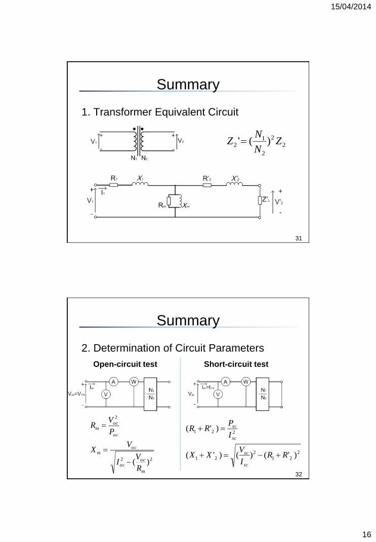
• Phase relationship
HV delta D
star Y
interconnected star Z
LV delta d
star y
interconnected star z
Group number Phase displacement Clock hour number
I 0o 0
II 180o 6
III -30o 1
IV 30o 11
Example:
Group I connection Yy0
30
Transformer Design and Construction
Group I Yy0
Group IV Yd11
Group IV Dy11
Group IV Yz11
• Phase relationship
15/04/2014
16
Summary
1. Transformer Equivalent Circuit
31
2
2
2
12 )(' Z
N
NZ
Summary
2. Determination of Circuit Parameters
32
22
2
)(m
ococ
ocm
oc
ocm
R
VI
VX
P
VR
2
21
2
21
221
)'()()'(
)'(
RRI
VXX
I
PRR
sc
sc
sc
sc
Open-circuit test Short-circuit test
15/04/2014
17
Summary
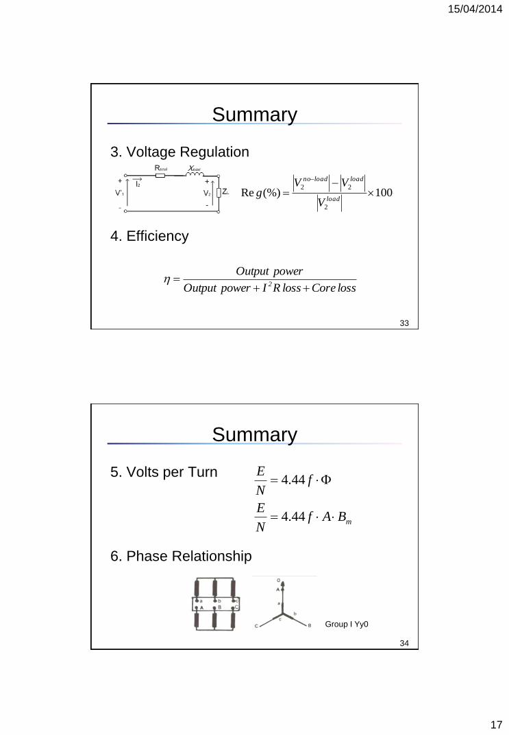
3. Voltage Regulation
4. Efficiency
33
100(%)Re2
22
load
loadloadno
V
VVg
loss Coreloss RIpower Output
power Output2
Summary
5. Volts per Turn
6. Phase Relationship
34
mBAfN
E
fN
E
44.4
44.4
Group I Yy0
15/04/2014
18
Reading…
• Power System Analysis
– John J. Grainger, William D. Stevenson.
35


![Intermediate-Scale Full State Quantum Circuit Simulation ...people.cs.uchicago.edu/~xinchuan/WU_APS_talk.pdf · Block [3] Compressed ... Project Number: 17-SC-20-SC, a collaborative](https://img.pdfslide.us/doc/110x75/5f79e0771659035dd6179eb5/intermediate-scale-full-state-quantum-circuit-simulation-xinchuanwuapstalkpdf.jpg)
![Solar cell operating principles · 2016. 2. 22. · Solar cell operating principles. PVI ffVImax mp mp oc sc= = η=PPffVIPmax I oc sc I= Short circuit current Isc [A] Open circuit](https://img.pdfslide.us/doc/110x75/60ce810ab7f24f60ea6e1b76/solar-cell-operating-principles-2016-2-22-solar-cell-operating-principles.jpg)


![EEE - · OC = 400 W P SC = 240 W Find the impedance of the approximate equivalent circuit referred to the primary side, and sketch the circuit. [Example 2.2, Chapman 4th edition] BPDB-14](https://img.pdfslide.us/doc/110x75/5aaacc8f7f8b9a90188e96f3/eee-400-w-p-sc-240-w-find-the-impedance-of-the-approximate-equivalent-circuit.jpg)