Embed Size (px)
Citation preview

Turk J Elec Engin, VOL.13, NO.1 2005, c© TUBITAK
A Realization of SC-CNN-Based Circuit Using FTFN
Enis GUNAY1, Esma UZUNHISARCIKLI2, Recai KILIC1, Mustafa ALCI1
1Erciyes University, Dep. of Electronic Engineering, 38039, Kayseri-TURKEYe-mail: [email protected], [email protected], [email protected] University, Kayseri Vocational College, Electronic Programme,
38039, Kayseri-TURKEYe-mail: [email protected]
Abstract
In this paper, a realization of the State Controlled Cellular Neural Network (SC-CNN)-based circuit
using Four Terminal Floating Nullor (FTFN) as active element is presented. In this realization, a new
version of autonomous Chua’s circuit has been considered using FTFN realization of SC-CNN-based
circuit. The performance of the proposed SC-CNN-based circuit is demonstrated by PSpice simulations.
Key Words: Cellular Neural Networks, FTFN, Chaos.
1. Introduction
In recent times, many studies were reported about chaotic circuits and their applications. From this pointof view, a variety of chaotic circuits have been used as chaos generator. Since it exhibits a rich variety ofbifurcations and chaos, the most preferable circuit as the chaos generator is Chua’s circuit [1].
On the other hand, since its definition by Chua & Yang [2], Cellular Neural Networks (CNNs) receiveda great deal of interest. Although many of these applications were proposed for numerous disciplines likeartificial life and image processing [3], some have been adapted for chaos [4-7]. In one of these applications,Arena et al. realized unfolded Chua’s circuit using the connection of three simple generalized CNN cellsand called this network structure as State-Controlled CNN (SC-CNN) [4]. The proposed SC-CNN-based
circuit is realized by using voltage-mode op amp (VOA) as an active element. Afterwards this SC-CNN
based circuit has been used in the chaos-based secure communication systems as a chaos generator [5,6]. Asan active element, VOAs have been used in a broad band of applications, e.g. filters, linear and non-linearamplifiers, analogue simulations etc. In the evolution of VLSI circuits, because of VOA’s certain limitationssuch as slew-rate problem and fixed gain-bandwidth product, designers changed the processed signal fromvoltage to current [8].
On the other hand, current-mode circuits are receiving much attention for their potential advantagessuch as wider dynamic range, inherent wide bandwidth, simpler circuitry and lower power consumptionthan voltage-mode circuits [9,10]. Among the current-mode circuits, four terminal floating nullor (FTFN)-based current-mode circuits are more flexible, versatile and stable active element in the synthesis of activenetworks than VOAs and current conveyors [8-14]. Because of the potential advantages of current-mode
39

Turk J Elec Engin, VOL.13, NO.1, 2005
signal processing techniques, in literature many methods have been investigated for transforming the well-developed voltage-mode circuit into their current-mode counterparts through the use of nullor model [9].
One of the implementations of the nullor model is an ideal voltage-mode op amp (VOA). It has been shownthat, the nullor equivalent of VOA can be replaced with the nullor equivalent of FTFN without imposingany restrictions [13].
In this paper, by utilizing the transformation between VOA and FTFN, the circuit realization of SC-CNN-based circuit has been constituted with FTFN. The organization of the paper is as follows: In Section2, the generation of Chua’s circuit dynamics using SC-CNN is given. In Section 3, the circuit realizationof the SC-CNN-based circuit using FTFN is described and simulation results are presented and finally aconclusion part is presented in Section 4.
2. SC-CNN-Based Circuit
As the most preferable chaos generator, diverse realizations of Chua’s circuit have been used in severalapplications. One of the realizations of Chua’s circuit has been derived by using a suitable connection ofthree simple generalized CNN cells. The proposed circuit has been called as the State Controlled-CellularNeural Network (SC-CNN) [4]. While the dimensionless state equations of the Chua’s circuit are defined asfollows:
x = α[y − h (x)]
y = x− y + z
z = −βy − γz
(1)
where
h (x) = m1 x+ 0.5 · (m0 −m1) × ( |x+ 1| − | x− 1| ) (2)
the proposed SC-CNN-based circuit is defined by the following nonlinear state equations [4]:
x1 = −x1 + a1y1 + s11x1 + s12x2
x2 = −x2 + s21x1 + s23x3
x3 = −x3 + s32x2 + s33x3
(3)
To obtain SC-CNN version of Chua’s circuit, the “a” and “s” parameters determined as a1 =α (m1 −m0);s33 = 1− γ ;s21 = s23 = 1s11 = 1−α ·m1 ; s12 = α ; and s32 = −β [4]. It is demonstrated that
the state equations of Chua’s circuit defined in Eq. (1) could be obtained with SC-CNN state equations.
The generalized cell circuit can be seen in Figure 1(a). To obtain the output non-linearity, R17 and R18
designed such that the A1 output saturates when |x1| > 1, and also designed R19 and R10 to scale the
output voltage –y1 in the range [-1,1] [4].
R18/R17 = VsatC1/Vsatx1 (4a)
40

GUNAY, UZUNHISARCIKLI, KILIC, ALCI: A Realization of SC-CNN-Based Circuit Using FTFN,
R17 /R18 = R10/ (R19 +R10) (4b)
A2 is an inverting amplifier and it has a unity gain, so R15 = R16 . From A3 , the SC-CNN cell stateequation can be written as follows:
Cjx′j = − xj
R4+
R3
R1R4V1 +
R3
R2R4V2 (5)
R11
C1
R16
+
-
R12
R18
- xj+
-
+
-
R13
A2
- V1
A3
R10
- V2
xj
R17
yj
R14
A 1
R15
R19
(a)
-V11
1-V
2
2
3-x
x
-x
-y
-V 1
-V2
-V1
-V 2
3
2-x
-y
cell-1
cell-2
cell-3
(b)
Figure 1. (a) The generalized cell circuit, (b) The cell connection scheme.
41

Turk J Elec Engin, VOL.13, NO.1, 2005
To realize Chua’s circuit, the three cells connection determined as, v1 = y1 and v2 = x2 for the firstcell, v1 = x1 and v2 = x3 for the second cell, v1 = -x2 , v2 = x3 for the third cell and this cell connectionscheme is given in Figure 1(b) [4]. To perform a double-scroll chaotic attractor as in original Chua’s circuit
with the parameter values β = 14.286, α = 9, γ = 0, m0 = −1/7 and m1 = 2/7, the parameter values ofSC-CNN based circuit chosen as R11 = 13.2 kΩ, R12 = 5.7 kΩ, R13 = 20 kΩ, R14 = 390 Ω, R15 = 100kΩ, R16 = 100 kΩ, R17 = 74.8 kΩ, R18 = 970 kΩ, R19 = 27 kΩ, R10 = 2.22 kΩ, C11 = 51nF for thefirst cell, R21 = R22 = R23 = R25 = R26 = 100 kΩ, R24 = 1 kΩ, C21 = 51nF for the second cell, R32
= R33 = R35 = R36 = 100 kΩ, R34 = 1 kΩ, R31 = 7.8 kΩ, C31 = 51nF for the third cell [4]. From the
cell connection scheme in Figure 1(b), it can be easily seen that there is no need to constitute an outputnon-linearity for the second and third cells. Then the usage of the resistors R27 , R28 , R29 , R20 and R37 ,R38 , R39 and R30 are unnecessary. While the dc characteristic of SC-CNN-based circuit is demonstratedin Figure 2, the chaotic dynamics observed in x1 , x2 and x3 cells, and the double scrolls between x1 -x2 ,x3 -x2 , and x1 -x3 cells of the SC-CNN-based circuit are shown in Figure 3 and Figure 4, respectively.
x100 0.50 1.00 1.50 2.00-1.00 -0.50-1.50-2.00
-1.00
-0.50
00
0.50
1.00
y1
Figure 2. The dc characteristic of SC-CNN-based circuit.
2.00
1.00
00
-1.00
-2.000s 1ms 2ms 3ms 4ms 5ms 6ms 7ms 8ms 9ms 10ms
Time(a)
x1
42

GUNAY, UZUNHISARCIKLI, KILIC, ALCI: A Realization of SC-CNN-Based Circuit Using FTFN,
400mV
200mV
00
-200mV
-400mV
4.00
2.00
00
-2.00
-4.00
0s 1ms 2ms 3ms 4ms 5ms 6ms 7ms 8ms 9ms 10msTime(b)
x2
0s 1ms 2ms 3ms 4ms 5ms 6ms 7ms 8ms 9ms 10msTime(c)
x3
Figure 3. The chaotic dynamics of SC-CNN-based circuit, (a) x1 dynamic, (b) x2 dynamic, (c) x3 dynamic.
3. FTFN Realization of SC-CNN Based Circuit
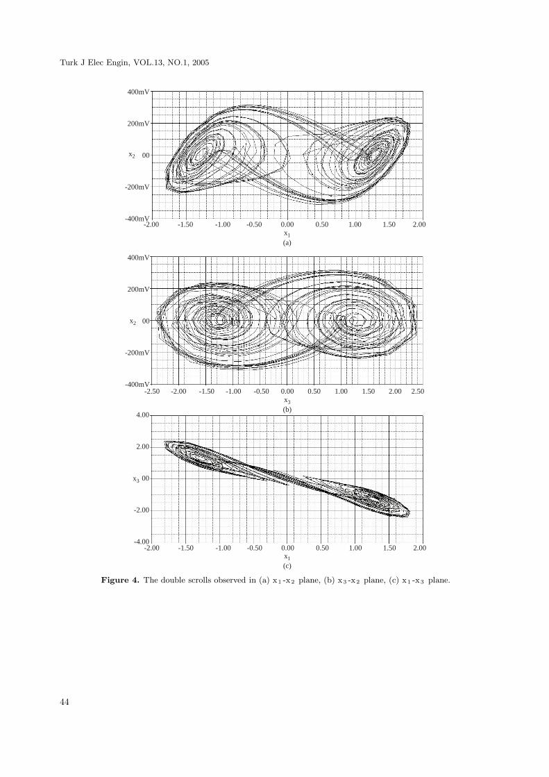
As theoretical active elements nullator with zero voltage and current, which is a one port two terminalelement, and norator with arbitrary voltage and current, which is a one port two terminal, have been usedin the synthesis of active networks. The union of nullator and norrator is called “nullor” and its symbol isgiven in Figure 5(a). It can be seen from Figure 5(a) that nullor has a nullator input and a norator output.
One of the implementations of the nullor model is an ideal voltage-mode op amp (VOA).
One can consider that VOA can be realized by using norator’s arbitrary output voltage and arbi-trary output current characteristics, and also nullator’s zero input voltage and zero input current flowingcharacteristics. So the nullor equivalent of the voltage-mode op amp can be seen in Figure 5(b).
On the other hand, in literature the FTFN is defined as the ideal nullor [12], and its generalized
nullor equivalent scheme and circuit symbol are given in Figure 6(a) and Figure 6(b), respectively. The portrelations of FTFN is characterized by the following equations:
V x = V y
Ix = Iy = 0Iz = Iw
(6)
43
Turk J Elec Engin, VOL.13, NO.1, 2005
400mV
200mV
00
-200mV
-400mV-2.00 -1.50 -1.00 -0.50 0.00 0.50 1.00 1.50 2.00
x1
(a)
x2
400mV
200mV
00
-200mV
-400mV
4.00
2.00
00
-2.00
-4.00
-2.50 -2.00 -1.50 -1.00 -0.50 0.00 0.50 1.00 1.50 2.00 2.50x3
(b)
x1
(c)
x2
x3
-2.00 -1.50 -1.00 -0.50 0.00 0.50 1.00 1.50 2.00
Figure 4. The double scrolls observed in (a) x1 -x2 plane, (b) x3 -x2 plane, (c) x1 -x3 plane.
44
GUNAY, UZUNHISARCIKLI, KILIC, ALCI: A Realization of SC-CNN-Based Circuit Using FTFN,
V 1 =0 V 2
I1
=0 I2
Nullator Norator
V1 V2
I1
I2
(a)
(b)
Figure 5. (a) The symbol for “nullor”, (b) The nullor equivalent of an ideal VOA.
wI w
I z zx
y I y
I x
w
I w
Izzx
y
I y
I xVx
Vy
Vz
Vw
(a)
(b)
Figure 6. (a) The nullor equivalent of FTFN, (b) The circuit scheme of FTFN.
45
Turk J Elec Engin, VOL.13, NO.1, 2005
x
y
FTFN
w
z
z
FTFN
x
x
z
w
FTFN
y
x
x
z
x
y w
z
FTFN
w
w
y
FTFN
FTFN
y
y
x
w
w
y
w
z
FTFN
z
z
FTFN
y
x
R11 R13
R12 R14
C1
R15
R17
R16
R18
R19
R10
R36
R35
C3
R34
R33
R32
R31
R22
R21 R23
R24
C2
R25
R26
Figure 7. The proposed FTFN realization of SC-CNN-based circuit.
x1
00 0.50 1.00 1.50 2.00-1.00 -0.50-1.50-2.00-1.00
-0.50
00
0.50
1.00
y1
Figure 8. The dc characteristic of the proposed circuit.
46

GUNAY, UZUNHISARCIKLI, KILIC, ALCI: A Realization of SC-CNN-Based Circuit Using FTFN,
400mV
200mV
00
-200mV
-400mV
4.00
2.00
00
-2.00
-4.00
2.00
1.00
00
-1.00
-2.00
0s 1ms 2ms 3ms 4ms 5ms 6ms 7ms 8ms 9ms 10msTime(b)
x2
0s 1ms 2ms 3ms 4ms 5ms 6ms 7ms 8ms 9ms 10msTime(a)
x1
0s 1ms 2ms 3ms 4ms 5ms 6ms 7ms 8ms 9ms 10msTime(c)
x3
Figure 9. The chaotic behaviors of proposed FTFN realization of SC-CNN-based circuit; (a) x1 dynamic, (b) x2
dynamic, (c) x3 dynamic.
Without imposing any restrictions the nullor equivalent of FTFN used instead of the nullor equivalentof VOA. In this transformation, by determining x port as the inverting input terminal, y port as the non-inverting input terminal, z port as the output terminal of a VOA, and also w port is grounded, FTFN canbehave as VOA.
In this paper, by utilizing this transformation between VAO and FTFN building blocks, without any
47

Turk J Elec Engin, VOL.13, NO.1, 2005
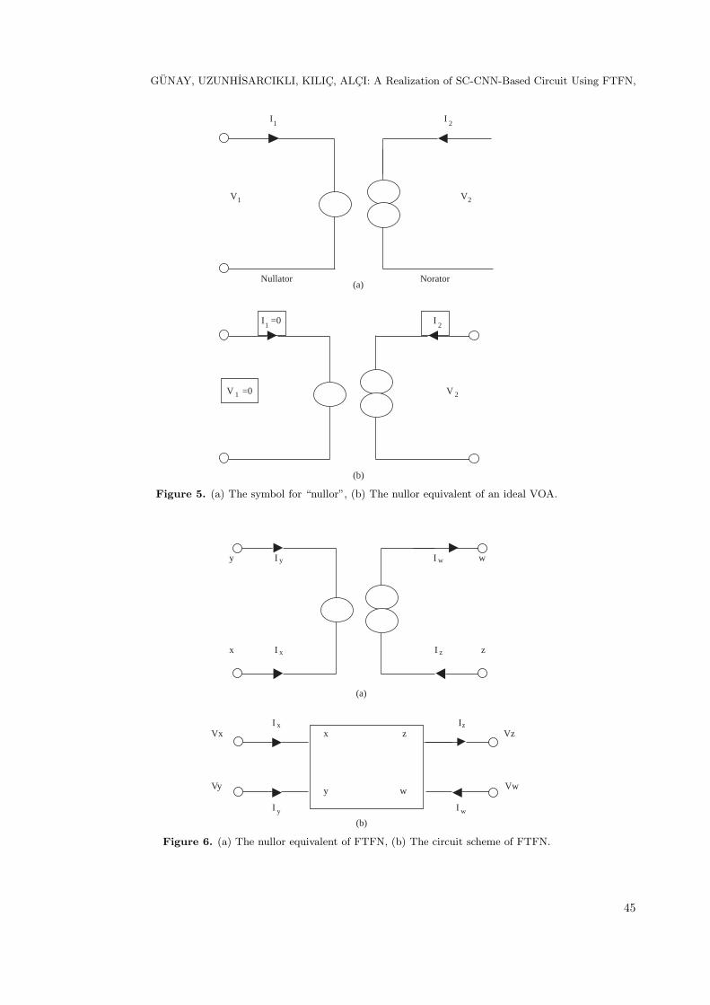
change in the other circuit elements and circuit connections, we used FTFN blocks instead of VOAs in Figure1(a). We obeyed the design considerations in Eqn. 4(a) and Eqn. 4(b).
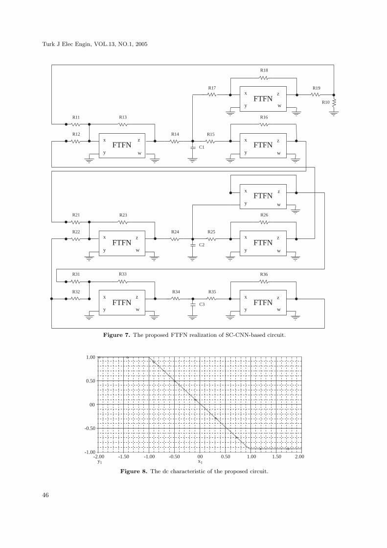
While there are no changes in circuit elements and circuit connections for A2 and for A3 , to formthe saturation of A1 output when |x1| > 1, and to scale the output voltage –y1 in the range [-1,1], theparameter values of R17 and R19 are redesigned, as 149.6K and 12.32K, respectively. The proposed FTFNrealization of SC-CNN-based circuit is given in Figure 7 and dc characteristic of the proposed circuit is givenin Figure 8.
400mV
200mV
00
-200mV
-400mV
4.00
2.00
00
-2.00
-4.00
400mV
200mV
00
-200mV
-400mV
-2.50 -2.00 -1.50 -1.00 -0.50 0.00 0.50 1.00 1.50 2.00 2.50x3 (b)
-2.00 -1.50 -1.00 -0.50 0.00 0.50 1.00 1.50 2.00x1 (a)
x1 (c)
x2
x2
x3
-2.00 -1.50 -1.00 -0.50 0.00 0.50 1.00 1.50 2.00
Figure 10. The chaotic attractors of proposed FTFN realization of SC-CNN-based circuit observed in (a) x1 -x2
plane, (b) x3 -x2 plane, (c) x1 -x3 plane.
48

GUNAY, UZUNHISARCIKLI, KILIC, ALCI: A Realization of SC-CNN-Based Circuit Using FTFN,
To perform PSpice simulations, a CMOS realization of FTFN, is used in literature with the sameparameters [12]. While the chaotic waveforms and double scroll attractors of the proposed circuit areillustrated in Figure 9 and in Figure 10, respectively.
4. Conclusion
A FTFN realization of SC-CNN-based circuit has been introduced. By using FTFN instead of VOA, analternative circuit realization of SC-CNN-based circuit has done. From simulation results, the chaoticdynamics and the chaotic attractors observed in FTFN-based circuits are harmonious to the ones observedin original circuits.
In literature the realization of inductorless Chua’s circuit using FTFN-based non-linear resistor andinductance simulator is also presented [14]. In that study, FTFN is only used in realization of a part ofChua’s circuit as non-linear resistor and inductance simulator. But in this study the whole circuit is realizedby using FTFN as an active element.
From another point of view, in literature it has been shown that SC-CNN-based circuit can easily usedas a chaos generator in chaos synchronization and chaos based secure communication systems [6,7,15]. Withthis study, the chaos synchronization and secure communication applications will be able to convenient tothe integration process by using FTFN-based SC-CNN circuit as CMOS based FTFN blocks are presentedin literature [12].
References
[1] L.O. Chua, C.W. Wu, A. Huang and G.A. Zhong, “Universal circuit for studying and generating chaos”, IEEE
Trans. Circuits& Syst., CAS-40, (10), pp. 732-745,1993.
[2] L.O. Chua and L Yang, “Cellular neural networks: Theory”, IEEE Trans. Circuits& Syst., 35, pp. 732-745,
1988.
[3] L.O. Chua., CNN: A Paradigm for complexity, World Scientific Series on Nonlinear Science, Series A- Vol. 31,
World Scientific Publishing, 1998.
[4] P. Arena, S. Baglio, L. Fortuna and G. Manganaro, “Chua’s circuit can be generated by CNN cells”, IEEE
Trans. Circuits& Syst.-I, 42, (2), pp.123-125, 1995.
[5] R. Caponetto, M. Criscione, L. Fortuna, D. Ochipinti, and L. Occhipinti, “Programmable chaos generator, based
on CNN architectures, with applications in chaotic communications”, Proc. of CNNA’98, pp. 124-129, 14-17
April, London, England, 1998.
[6] R. Kılıc, M. Alcı and E. Gunay, “A SC-CNN-based chaotic masking system with feedback”, Int. J. Bifurcation
and Chaos, 14, (1), pp. 245-256, 2004.
[7] E. Gunay, M. Alcı, R. Kılıc, “A Chaos Synchronization Study: Continuous & Impulsive Synchronization Between
SC-CNN-Based Circuit and Chua’s Circuit”, Proceeedings of the 2003 Workshop on Nonlinear Dynamics of
Electronic Systems, pp.97-100, 2003.
[8] M. Higashimura, “Realisation of Current-Mode Transfer Function Using Four-Terminal Floating Nullor”, Elec-
tronic Letters, Vol. 27, no.2, pp. 170-171, 1991.
49

Turk J Elec Engin, VOL.13, NO.1, 2005
[9] M.T. Abuelma’atti, H.A. Al-Zaher, “Current- Mode Sinusoidal Oscillators Using Two FTFNs”, Proc. Natl. Sci.
Counc. ROC(A), Vol. 22, No. 6, pp. 758-764, 1998.
[10] I.A. Awad and A.M. Soliman, “Inverting Second Generation Current Conveyors: the missing building blocks,
CMOS realizations and applications”, Int. Journal of Electronics, 86, (4), pp. 413-432,1999.
[11] A.M. Soliman, “Generation of Current Conveyor-Based All-Pass Filters From Op Amp-Based Circuits”, IEEE
Transaction on Circuit Systems-II:Analog and Digital Signal Processing, 44, 324-330, 1997.
[12] U. Cam & H. Kuntman, “A new CMOS realization of four terminal floating nullor (FTFN)”, Int. Journal of
Electronics, 87, (7), pp. 809-817, 2000.
[13] L. Odess, H. Ur, “Nullor Equivalent Networks of Nonideal Operational Amplifiers and Voltage-Controlled
Sources”, IEEE Transactions on Circuits and Systems, 27, pp. 231-235, 1980.
[14] R. Kılıc, U. Cam, M. Alcı, H. Kuntman, E. Uzunhisarcıklı, “Realization of Inductorless Chua’s Circuit Using
FTFN-Based Nonlinear Resistor and Inductance Simulator”, Frequenz, 58, 1-2, pp. 1-4, 2004.
[15] R. Kılıc, “Chaos Synchronization in SC-CNN-Based Circuit and an Interesting Investigation: Can A SC-CNN-
Based Circuit Behave Synchronously With The Original Chua’s Circuit?”, Int. J. Bifurcation and Chaos, 14,
(3), pp. 1071-1083, 2004.
50