Embed Size (px)
Citation preview
Introduction The Overall Polarimetry Concept Simulation Studies Testbeam Summary & Outlook
Towards Precision Polarimetry at the ILC:
Concepts, Simulations, Testbeam Results
C. Bartels, C. Helebrant, Dr. D. Kafer, Dr. J. List
DESY Hamburg
NSS, Dresden, October 23, 2008
IntroductionThe Overall Polarimetry ConceptSimulation StudiesTestbeamSummary & Outlook
Towards Precision Polarimetry at the ILC Dr. J. List 1
Introduction The Overall Polarimetry Concept Simulation Studies Testbeam Summary & Outlook
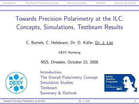
The International Linear Colliderthe goals:
I Unveil the nature of physics beyond the Standard Model
I precision measurements of known and new particles
the tools:
I Electron - positron collisions at√
s = 90 GeV up to 1 TeV
I Polarisation: Pe− = 80-90%, Pe+ = 30-60%
the challenge:
I determine luminosity weighted average polarisation at thecollision point to δP/P = 0.1%
I ... and in some cases even to δP/P = 0.01%
Towards Precision Polarimetry at the ILC Dr. J. List 2
Introduction The Overall Polarimetry Concept Simulation Studies Testbeam Summary & Outlook
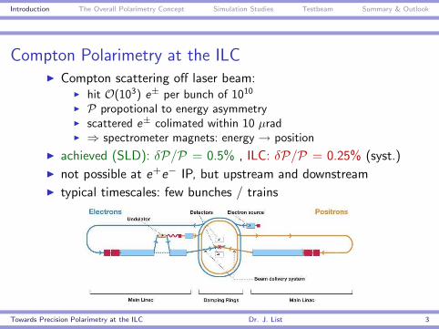
Compton Polarimetry at the ILCI Compton scattering off laser beam:
I hit O(103) e± per bunch of 1010
I P propotional to energy asymmetryI scattered e± colimated within 10 µradI ⇒ spectrometer magnets: energy → position
I achieved (SLD): δP/P = 0.5% , ILC: δP/P = 0.25% (syst.)
I not possible at e+e− IP, but upstream and downstream
I typical timescales: few bunches / trains
Towards Precision Polarimetry at the ILC Dr. J. List 3
Introduction The Overall Polarimetry Concept Simulation Studies Testbeam Summary & Outlook
Polarimetry with Annihilation Data
e+e− → W +W−
I from total cross-section or dσd cos θ
I contribution of new physics?⇒ common determination with triple gauge couplings
I longterm (O (years)) absolute scale to δP/P = 0.1%
c.f. LC-PHSM-2001-022, update underway
Blondel Scheme
I needs Pe+ 6= 0 and all four e± helicity combinations
I determines Peff =|Pe− |+|Pe+ |
1+|Pe− | |Pe+ | to δPeff/Peff = 0.01%
c.f. K. Monig, LCWS S2004
Towards Precision Polarimetry at the ILC Dr. J. List 4
Introduction The Overall Polarimetry Concept Simulation Studies Testbeam Summary & Outlook
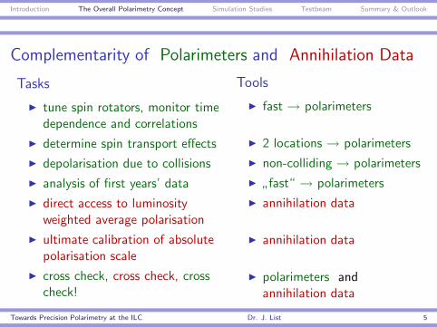
Complementarity of Polarimeters and Annihilation Data
Tasks
I tune spin rotators, monitor timedependence and correlations
I determine spin transport effects
I depolarisation due to collisions
I analysis of first years’ data
I direct access to luminosityweighted average polarisation
I ultimate calibration of absolutepolarisation scale
I cross check, cross check, crosscheck!
Tools
I fast → polarimeters
I 2 locations → polarimeters
I non-colliding → polarimeters
I”fast“ → polarimeters
I annihilation data
I annihilation data
I polarimeters andannihilation data
Towards Precision Polarimetry at the ILC Dr. J. List 5
Introduction The Overall Polarimetry Concept Simulation Studies Testbeam Summary & Outlook
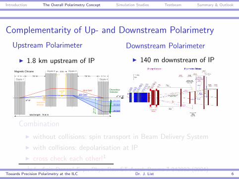
Complementarity of Up- and Downstream Polarimetry
Upstream Polarimeter
I 1.8 km upstream of IP
+e /e
+e /e IP
Dipole 18.1m
Dipole 2
8.1m
Dipole 4
Dipole 3
16.1m
8 m
16.1m
CherenkovDetector
total length: 74.6 m
125 GeV
25 GeV
50 GeV
Magnetic Chicane
laserwiredetector
250 GeV24
cm
45.6 GeV
inout
LaserIP
?
Downstream Polarimeter
I 140 m downstream of IP
Combination
I without collisions: spin transport in Beam Delivery System
I with collisions: depolarisation at IP
I cross check each other!1
1c.f.”Spin Dance“ Exp., Phys. Rev. ST Accel. Beams 7 042802 (2004)
Towards Precision Polarimetry at the ILC Dr. J. List 6
Introduction The Overall Polarimetry Concept Simulation Studies Testbeam Summary & Outlook
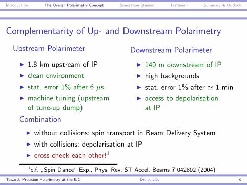
Complementarity of Up- and Downstream Polarimetry
Upstream Polarimeter
I 1.8 km upstream of IP
I clean environment
I stat. error 1% after 6 µs
I machine tuning (upstreamof tune-up dump)
Downstream Polarimeter
I 140 m downstream of IP
I high backgrounds
I stat. error 1% after ' 1 min
I access to depolarisationat IP
Combination
I without collisions: spin transport in Beam Delivery System
I with collisions: depolarisation at IP
I cross check each other!1
1c.f.”Spin Dance“ Exp., Phys. Rev. ST Accel. Beams 7 042802 (2004)
Towards Precision Polarimetry at the ILC Dr. J. List 6
Introduction The Overall Polarimetry Concept Simulation Studies Testbeam Summary & Outlook
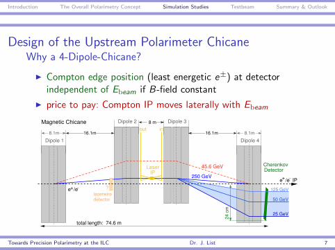
Design of the Upstream Polarimeter ChicaneWhy a 4-Dipole-Chicane?
I Compton edge position (least energetic e±) at detectorindependent of Ebeam if B-field constant
I price to pay: Compton IP moves laterally with Ebeam
+e /e
+e /e IP
Dipole 18.1m
Dipole 2
8.1m
Dipole 4
Dipole 3
16.1m
8 m
16.1m
CherenkovDetector
total length: 74.6 m
125 GeV
25 GeV
50 GeV
Magnetic Chicane
laserwiredetector
250 GeV
24 c
m
45.6 GeV
inout
LaserIP
?
Towards Precision Polarimetry at the ILC Dr. J. List 7
Introduction The Overall Polarimetry Concept Simulation Studies Testbeam Summary & Outlook
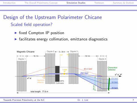
Design of the Upstream Polarimeter Chicane
Scaled field operation?
I fixed Compton IP position
I facilitates energy collimation, emittance diagnostics
+e /e
+e /e IP
16.1m
Dipole 3
16.1m 8.1m
Dipole 4
Dipole 2
Dipole 18.1m
125 GeV
25 GeV
50 GeV
24 c
mtotal length: 77.6 m
MPSCollimator
CherenkovDetector
laserwiredetector
?
LaserIP
out inMagnetic Chicane 3 + 8 m
250 GeV
45.6 GeV
Towards Precision Polarimetry at the ILC Dr. J. List 7
Introduction The Overall Polarimetry Concept Simulation Studies Testbeam Summary & Outlook
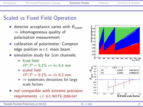
Scaled vs Fixed Field Operation
I detector acceptance varies with Ebeam
⇒ inhomogeneous quality ofpolarisation measurement
I calibration of polarimeter: Comptonedge position w.r.t. main beam
I simulation study for 1cm channels:I fixed field:δP/P = 0.1% ⇔ δx 0.4 mm
I scaled field:δP/P = 0.1% ⇔ δx 0.2 mm
I ⇒ systematic deviations for largescale factors
I not compatible with extreme precisionrequirements c.f. ILC-NOTE-2008-047
(GeV)beam E0 50 100 150 200 250 300 350 400 450 500
det
ecto
r ac
cept
ance
(m)
0
0.02
0.04
0.06
0.08
0.1
0.12
0.14
0.16
0.18 fixed field Compton edge
fixed dispersion Compton edge
zero crossing
-0.25
-0.2
-0.15
-0.1
-0.05
0
0.05
0.1
0.15
0.2
0.25
0 0.2 0.4 0.6 0.8 1 1.2
1.873 / 4P1 -0.2243 0.8276E-01P2 0.2250 0.8986E-01
B-Field scale factor
P mea
s - P
true
Towards Precision Polarimetry at the ILC Dr. J. List 8
Introduction The Overall Polarimetry Concept Simulation Studies Testbeam Summary & Outlook
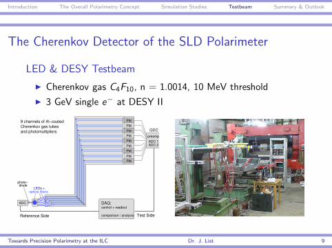
The Cherenkov Detector of the SLD Polarimeter
LED & DESY Testbeam
I Cherenkov gas C4F10, n = 1.0014, 10 MeV threshold
I 3 GeV single e− at DESY II
PM
PM
PM
PM
PMPM
PM
PM
PM
control + readout
comparison / analysis
DAQ:
Cherenkov gas tubes9 channels of Al−coated
and photomultipliers
LEDs +optical fibers
photo−diode
ADC
Reference Side
preampADC 1ADC 2
QDC
Test Side
Towards Precision Polarimetry at the ILC Dr. J. List 9
Introduction The Overall Polarimetry Concept Simulation Studies Testbeam Summary & Outlook
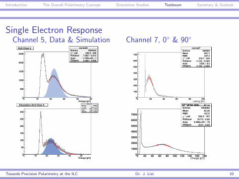
Single Electron ResponseChannel 5, Data & Simulation
normal5Entries 1000434
/ ndf 2χ 448.3 / 449PhElectr 0.013± 7.082 Area 1± 1.104e+04 GSigma 0.000± 2.489
Charge [pC]0 10 20 30 40 500
500
1000
1500
2000
2500
normal5Entries 1000434
/ ndf 2χ 448.3 / 449PhElectr 0.013± 7.082 Area 1± 1.104e+04 GSigma 0.000± 2.489
normal5Entries 1000434
/ ndf 2χ 448.3 / 449PhElectr 0.013± 7.082 Area 1± 1.104e+04 GSigma 0.000± 2.489
SLD Chan 5
sim_0_5Entries 50000
/ ndf 2χ 714.4 / 717PhElectr 0.000± 6.048 Area 43.6± 873.8 GSigma 0.360± 2.971
Charge [pC]0 10 20 30 40 500
50
100
150
200
250
300
sim_0_5Entries 50000
/ ndf 2χ 714.4 / 717PhElectr 0.000± 6.048 Area 43.6± 873.8 GSigma 0.360± 2.971
Simulation SLD Chan 5 sim_0_5Entries 50000
/ ndf 2χ 714.4 / 717PhElectr 0.000± 6.048 Area 43.6± 873.8 GSigma 0.360± 2.971
Channel 7, 0◦ & 90◦normal7
Entries 200000Mean 891.7RMS 447.2
/ ndf 2χ 516.7 / 345PhElectr 0.000± 4.133 Area 8.0± 2338 GSigma 0.000± 2.108
Ladung [pC]0 20 40 60 80 1000
100
200
300
400
500
600
700
normal7Entries 200000Mean 891.7RMS 447.2
/ ndf 2χ 516.7 / 345PhElectr 0.000± 4.133 Area 8.0± 2338 GSigma 0.000± 2.108
Towards Precision Polarimetry at the ILC Dr. J. List 10
Introduction The Overall Polarimetry Concept Simulation Studies Testbeam Summary & Outlook
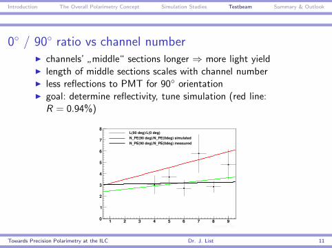
0◦ / 90◦ ratio vs channel numberI channels’
”middle“ sections longer ⇒ more light yield
I length of middle sections scales with channel numberI less reflections to PMT for 90◦ orientationI goal: determine reflectivity, tune simulation (red line:
R = 0.94%)
Towards Precision Polarimetry at the ILC Dr. J. List 11
Introduction The Overall Polarimetry Concept Simulation Studies Testbeam Summary & Outlook
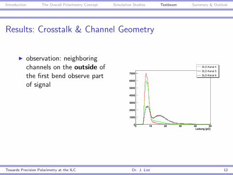
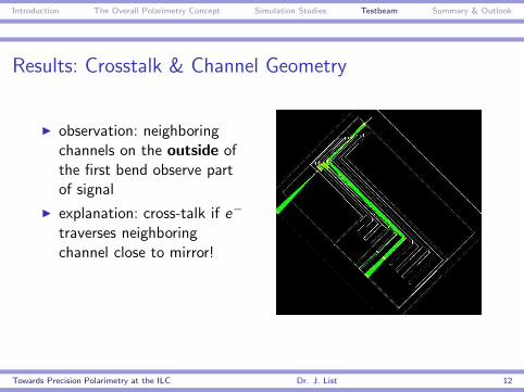
Results: Crosstalk & Channel Geometry
I observation: neighboringchannels on the outside ofthe first bend observe partof signal
Towards Precision Polarimetry at the ILC Dr. J. List 12
Introduction The Overall Polarimetry Concept Simulation Studies Testbeam Summary & Outlook
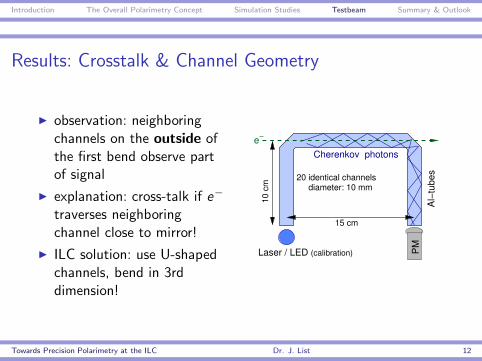
Results: Crosstalk & Channel Geometry
I observation: neighboringchannels on the outside ofthe first bend observe partof signal
I explanation: cross-talk if e−
traverses neighboringchannel close to mirror!
Towards Precision Polarimetry at the ILC Dr. J. List 12
Introduction The Overall Polarimetry Concept Simulation Studies Testbeam Summary & Outlook
Results: Crosstalk & Channel Geometry
I observation: neighboringchannels on the outside ofthe first bend observe partof signal
I explanation: cross-talk if e−
traverses neighboringchannel close to mirror!
I ILC solution: use U-shapedchannels, bend in 3rddimension!
e
20 identical channels diameter: 10 mm
10 c
m
PM
15 cm
Al−
tube
s
Cherenkov photons
Laser / LED (calibration)
Towards Precision Polarimetry at the ILC Dr. J. List 12
Introduction The Overall Polarimetry Concept Simulation Studies Testbeam Summary & Outlook
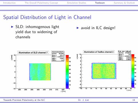
Spatial Distribution of Light in Channel
I SLD: inhomogenous lightyield due to widening ofchannels
I avoid in ILC design!
Towards Precision Polarimetry at the ILC Dr. J. List 13
Introduction The Overall Polarimetry Concept Simulation Studies Testbeam Summary & Outlook
Summary
I precision goals of ILC require combination of upstream anddownstream polarimeters as well as annihilation data
I best design for upstream polarimeter is a four-magnet chicanewith fixed field operation at all beam energies
I polarimters should improve by factor of 2 w.r.t. SLD
I Cherenkov detector of SLD has been operated in testbeam
I good agreement with simulation
I several improvements for ILC design identified
Towards Precision Polarimetry at the ILC Dr. J. List 14
Introduction The Overall Polarimetry Concept Simulation Studies Testbeam Summary & Outlook
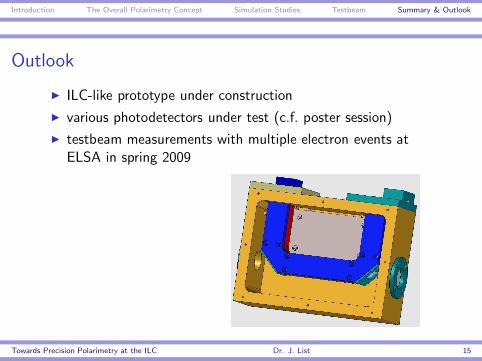
Outlook
I ILC-like prototype under construction
I various photodetectors under test (c.f. poster session)
I testbeam measurements with multiple electron events atELSA in spring 2009
Towards Precision Polarimetry at the ILC Dr. J. List 15
Introduction The Overall Polarimetry Concept Simulation Studies Testbeam Summary & Outlook
BACKUP
Towards Precision Polarimetry at the ILC Dr. J. List 16
Introduction The Overall Polarimetry Concept Simulation Studies Testbeam Summary & Outlook
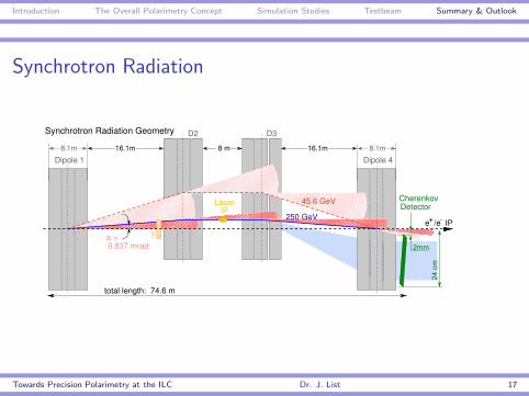
Synchrotron Radiation
+e /e IP������������������������������������������������������������������������������������������������������������������������������������������������������������������������������������������������������������������������������������������
�������������������������������������������������������������������������������������������������������������������������������������������������������������������������������������������������������������������������������������������������������������������������
����������������������������������������������������������������������������������������������������������������������������
�����������������������������������������������������������������������������������������������������������������������������������������������������������
������������������������������������������������������������������������������������������������������������������������������������������������������������������������������������������������������
������������������������������������������������������������������������������������������������������������������������������������������������������������������������������������������������������
������������������������������������������������������������
���������������������������������������������������������������������������������������������������������������
���������������������������������������������������������������������������������������������
� � � � � � � � � � � � � � � � � � � � � � � � � � � � � � � � � � � � � � ������������������������������������������������������������������������������
���������������������������������������������������������
Dipole 18.1m 8.1m
Dipole 416.1m 16.1m
D3D2
8 m
a =0.837 mrad
CherenkovDetector
24 c
m
2mm
?
total length: 74.6 m
250 GeV
Synchrotron Radiation Geometry
45.6 GeVIP
Laser
Towards Precision Polarimetry at the ILC Dr. J. List 17