Embed Size (px)
Citation preview

Page 1
Toucan Touchscreen Gauge and CAL Selection Unit
User Guide (Syvecs) V1.34 For Toucan Firmware Version 1.34 and above
Disclaimer
www.JTi.uk.com [email protected]
JT Innovations Ltd Parkview
4A, Easton Square Portland Dorset
UK DT5 1BX
+44 (0) 1305 534535
© JT Innovations Ltd. 2014
Disclaimer
Although every care is taken with the design of this product, JT Innovations Ltd. can in no way be held responsible for any consequential damage resulting from
the use of Toucan in your vehicle.
Always operate your vehicle safely and do not allow yourself to be distracted by your Toucan display while driving. Minimise the amount of time you spend
viewing the screen. Do not access any function requiring prolonged use of the menus whilst driving.

Page 2
Contents Toucan Touchscreen Gauge and CAL Selection Unit ......................................... 1
User Guide (Syvecs) V1.34 ...................... 1
Introduction ............................................ 3
Installation .............................................. 3
Before You Start ................................. 3
Installation .......................................... 3
Connectors...................................... 3
Power .............................................. 4
CAL Switch ...................................... 4
RJ25 Data Connector ...................... 5
Multiway Connector ....................... 5
In-vehicle Mounting ........................ 5
Initial Toucan Configuration ............... 6
CAL switch configuration ................ 6
Doesn’t work? ................................. 7
Menus and Operation ............................. 8
Gauge Screens .................................... 8
Settings Menu ..................................... 9
Setup Menu ........................................ 9
Gauge Layout .................................... 10
CAL Selection Menu .......................... 10
Traction Control Selection Menu ...... 10
Editing CAL Text ............................ 11
CAL Voltage Adjustment ................... 11
CAL PIN Protection............................ 12
Alarm Configuration ......................... 13
Available Alarms ........................... 14
“More” Menus .................................. 15
CANbus/Custom RS232 ......................... 16
CANbus Termination ......................... 16
Syvecs CAN bus configuration ........... 16
CANbus Doesn’t Work? ................. 17
Advanced CAN configuration ................ 17
Frame/Slot Assignments ................... 17
Turning Parameters Off ................ 18
Extended Gauge Set. ..................... 18
Status Indicators ........................... 18
Enable CAN Control .......................... 18
Sensor Alarms ....................................... 19
Firmware Updates ................................ 19
Multiple Toucan Units .......................... 19
Technical ............................................... 20
Glossary ................................................ 20

Page 3
Introduction Thank you for purchasing a Toucan display. We hope it will be easy to install and configure, and suggest that you read this guide before you start. It is recommended that you register your product in the JT Innovations website – this way we can keep you advised of any product updates etc.
Installation
Before You Start Please check the box contents to ensure nothing is missing. You should have:
Unit Cable Harness Mount (one of the following)
Installation
Connectors
ENSURE THE CAR BATTERY IS DISCONNECTED BEFORE ATTEMPTING TO INSTALL YOUR TOUCAN DISPLAY UNIT
IF IN DOUBT, PLEASE CONSULT A QUALIFIED AUTOMOTIVE ELECTRICIAN
BLACK Power Ground YELLOW Permanent +12V RED Switched +12V ORANGE Lighting circuit GREY CAL Switch
Multiway Connects to Toucan unit
RJ25 Data connection to Syvecs

Page 4
Power The power connectors are provided with “bullet” connectors which may be removed if preferred. Each power feed has an inline fuse holder pre-fitted with a 1 amp 20mm glass fuse. Ensure a good ground connection is provided to the BLACK wire.
To allow Toucan to power up quickly, it is recommended that a connection to both a permanent and switched (i.e. only live when the ignition is on) vehicle battery feed are made. When the ignition is off, Toucan will consume about 40 milliamps from the permanent connection – a typical, healthy, 40 amp-hour vehicle battery will last over a month before being run completely flat by Toucan: but it’s your choice.
If you decide not to connect the YELLOW permanent +12 Volt, please make sure it is wired along with the RED connection to the switched ignition feed; otherwise Toucan may not start up when you turn on the ignition.
Toucan will take about 6 seconds to start if the permanent +12 Volt feed is not connected compared to less than a second when the permanent connection is made.
A connection to the vehicle lighting circuit may be made using the ORANGE connector – this will allow the Toucan unit to automatically dim when the vehicle lights are turned on. If not required, please insulate the unused wire to prevent damage to the unit or vehicle.
CAL Switch The long GREY wire, also equipped with a bullet connector, may be connected to the Syvecs CAL switch input to allow you to use Toucan to select the required calibration. V1.30 onwards Toucan firmware supports CAL control via CAN bus, so this grey wire can either be ignored (please make sure the bare end is insulated) or used as a traction control (or other) selection switch.
The CAL switch for Subaru S6PnP ECUs is often wired to the green “test” connector located above the pedal box, near the steering column as shown below/left.
One of these two connectors is simply a ground connection: for “newage” vehicles (MY01 onwards) it is the female/receptacle connector that you need to connect to, as shown above/right. For “classic” vehicles, MY00 and earlier, it is usually the male connector – but sometimes it can be the black connectors: it is best to check with your mapper/fitter if you’re not sure.

Page 5
Syvecs S6PnP RJ25
CAL switches for S6GP and S8 ecu’s are usually wired directly to the ecu connector or loom adapter to an “AR” input, but check your own Syvecs installation and wiring schedule to be sure.
RJ25 Data Connector S6PnP ecu’s are provided with an RJ25 socket on the front edge of the ecu, adjacent to the Ethernet connector. Plug Toucan’s RJ25 connector directly in to this socket. Make sure you do not connect it to the larger Ethernet connector as Toucan will not work – the usual symptom of this is that Toucan enters a self-test routine.
S6GP and S8 ecu’s are not provided with a mating connector, so the RJ25 should be cut off and the cores wired as follows1. Make sure any unused wires are separated and individually insulated – shorting the RS232 pins will also put Toucan into its self-test mode.
RJ11 Cable Core Syvecs Function Syvecs S6 Pin
Syvecs S8 Pin
Pin 1 green RS232 RX 55 48 Pin 2 green/white RS232 TX 56 21 Pin 4 brown CAN HI 53 82 Pin 5 brown/white CAN LO 54 81
Multiway Connector This connects to the rear of the Toucan unit. Note that it has a latching tab that must be depressed before the connector and cable can be detached.
The connector is intended to allow occasional removal of the unit from the car to allow, for example, firmware updates to be applied.
When detaching the unit, take care not to put unnecessary strain on the wires otherwise they may be damaged.
In-vehicle Mounting Toucan uses the Herbert Richter™ 4-prong mount system, which provides a secure mount when in the vehicle, but easy removal should it be required.
1 Note: some cables supplied have a different colour coding. Pin 1 (RS232 RX) is brown; Pin 2
(RS232 TX) is green; Pin 4 (CAN HI) is green; Pin 5 (CAN LO) is violet.

Page 6
The default mount supplied is a permanent type which is intended to be permanently screwed to the vehicle. Make sure the mount is in the location you require before attaching it. An alternative mount may have been selected when you purchased your unit, or they may be purchased separately if required.
Initial Toucan Configuration Having checked the installation of your Toucan, ensuring all connectors are fully home and especially that the power wiring is correct, reconnect the vehicle battery and turn on the ignition, but do not start the engine at this time. After a few seconds, Toucan should power up and display the main gauge screen.
CAL switch configuration If Toucan is being used to select calibrations via the grey wire, it is necessary to check that the voltage thresholds configured in the Syvecs ecu match those of your Toucan. Toucan supports 8 or 12 CAL positions. The analogue rotary CAL switches do vary from sample to sample and your mapper may have adjusted the values in the Syvecs to match your specific switch. These are typical Syvecs threshold values, as well as the default Toucan voltages:
8 CAL POSITIONS
CAL Syvecs threshold
Toucan Voltage
1 <0.36V 0.00V 2 >0.36V, <1.07V 0.70V 3 >1.07V, < 1.68V 1.40V 4 >1.68V, < 2.19V 1.95V 5 >2.19V, <2.79V 2.50V 6 >2.79V, <3.20V 3.00V 7 >3.20V, <3.61V 3.40V 8 >3.61V 4.00V
12 CAL POSITIONS
CAL Syvecs threshold
Toucan Voltage
1 <0.42V 0.00V 2 >0.42V, < 0.83V 0.60V 3 >0.83V, < 1.25V 1.00V 4 >1.25V, < 1.67V 1.40V 5 >1.67V, < 2.08V 1.85V 6 >2.08V, < 2.50V 2.30V 7 >2.50V, < 2.92V 2.70V 8 >2.92V, < 3.33V 3.20V 9 >3.33V, < 3.75V 3.50V
10 >3.75V, < 4.17V 3.90V 11 >4.17V, < 4.58V 4.30V 12 >4.58V 4.80V

Page 7
To ensure Toucan and your Syvecs match, you can either alter the voltages in the Toucan unit, or alter the Syvecs calibration to match Toucan: in either case you will need to examine the Syvecs calibration. If you are not confident to do this, please contact your mapper, or contact technical support at JT Innovations for assistance.
Note that switching Toucan between 8 and 12 CAL positions will cause the voltages to default to the values in the tables above.
See the basic operation guide for how to adjust the CAL voltage output of Toucan.
Once the CAL voltages have been set, you can start the engine and begin to explore the gauge and other options available in your Toucan unit.
Doesn’t work? Double check installation, especially the data connection to the Syvecs unit: is it
plugged in to the Ethernet connection by mistake?
Remove the cable from Toucan and re-attach a few seconds later – this will give the unit a reset.
By default, Toucan connects using CANbus data. The Syvecs ecu may not have been configured to transmit CAN data, or the datastream may not be configured correctly. Try changing Toucan to use RS232 STACK or the Syvecs custom protocol. This is described in the basic operation guide – the setting is in the “MORE” menus.
Contact technical support at JT Innovations for assistance.

Page 8
Menus and Operation Gauge Screens
Four gauge screens are available with complete flexibility of which gauge is displayed where. This can be configured via the Gauge Select pages, accessible via the “Gauge Setup” button.
Only readings from sensors that are actually connected to the Syvecs ecu and configured correctly will be displayed.
Large Gauges
Touch here to go to next gauge page
AntiLag status
Not present – not active
Yellow – start CAL
Green – active
Red - shutdown
Touch here to go to previous gauge page
Launch Control status
Red - OFF
Yellow – armed, not active
Green – active
Touch here to change current calibration. Label shown is the first 5 characters of the text entered.
Shows which gauge screen is showing: A, B, C or D.
Touch the centre of any gauge to display the full screen version and then cycle through all gauges or reset the peak marker.
Press and hold any gauge to display the most recently shown large gauge.
Return to the main gauge screen by touching the centre of the large gauge.
Touch here to enter SETTINGS menus
Shows Knock ignition retard has exceeded set value on any 1 or more cylinders (CANbus only). Also shows sensor alarms and limp/cut mode.
Touch to show knock, limp mode or sensor alarm full screen “gauge”.
Shows current Traction Control CAL. Touch to edit the names for each TC CAL and, if enabled, change the TC CAL. Labell shown here is the first FIVE characters off the entered text
Touch here to mute an active alarm. Will be automatically unmuted when the alarm next clears
Resets the peak marker.
Goes to parameter list view.
Touch here to return to main gauge screen.

Page 9
Settings Menu
If the “illumination” wire has been wired to the vehicle’s lighting circuit, the manual day and night buttons will temporarily override the brightness as controlled from the vehicle.
Setup Menu
Touch here to mute or unmute audible alarms.
Touch here to return to gauge screen
Touch here to select full brightness
Touch here dim display to night brightness. Touch and hold to display a dimmed screen with no gauge activity, useful when the screen could be distracting. Touch here to enter
SETUP menus
Touch here to change current calibration
Touch here to configure alarms.
Touch here to return to settings menu
Touch here to adjust night brightness level
Touch here to adjust CAL voltages
Touch here to choose gauge layout and colour scheme
Touch here for “More” menus

Page 10
Gauge Layout This is accessed via the Gauge Setup button, and then “Gauge Select”.
CAL Selection Menu
Traction Control Selection Menu This is identical in operation to the CAL adjust function.
Note that the TC CAL cannot, by default, be actually changed from the TC CAL menu as Toucan only has a single control voltage output, which is used for the main CAL adjustment. However, if “CAN Control” is enabled (see later) then the main CAL control is effected via CAN bus and, then, the original CAL output voltage will be driven from the TC menu instead.
User Text describing this calibration
Touch here to return to previous menu
Next and previous buttons to select a different CAL
Touch here to edit the User Text
First 5 characters of this text used on main gauge screen as label.
Touch the gauge that you wish to change. A 3 letter mnemonic describes the current gauge selected for each position
Touch here cycle between the next and previous gauges in the list
Touch here to select which of the 4 pages to setup
Gauge name is shown here
A unique “CAL Override” button may be placed here only, on one or more pages.
See “Advanced CAN configuration”
The two smallest gauge positions
The two smallest gauge positions can be used for generic status indicators on one or more pages. See “Advanced CAN configuration.
Page 11
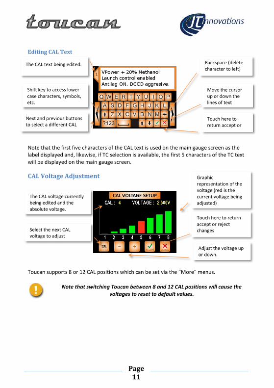
Editing CAL Text
Note that the first five characters of the CAL text is used on the main gauge screen as the label displayed and, likewise, if TC selection is available, the first 5 characters of the TC text will be displayed on the main gauge screen.
CAL Voltage Adjustment
Toucan supports 8 or 12 CAL positions which can be set via the “More” menus.
Note that switching Toucan between 8 and 12 CAL positions will cause the voltages to reset to default values.
Backspace (delete character to left)
Touch here to return accept or reject changes
Next and previous buttons to select a different CAL
Move the cursor up or down the lines of text
Shift key to access lower case characters, symbols, etc.
The CAL text being edited.
Graphic representation of the voltage (red is the current voltage being adjusted)
Adjust the voltage up or down.
Select the next CAL voltage to adjust
Touch here to return accept or reject changes
The CAL voltage currently being edited and the absolute voltage.

Page 12
CAL PIN Protection. If enabled via the “more” menus, Toucan can be set to prevent the current CAL being changed unless you enter a 4 digit PIN. This can be useful if you have a “valet” CAL (with reduced rpm limit for example) and/or an anti-theft CAL. You can also set PIN protection to only apply to the last CAL (i.e. CAL 8 or 12), only to the first CAL or to both the first and last CAL.
There are a few things to be aware of if you choose to use this option:
The default PIN is 0000 and it is recommended that you change this to something else.
Once PIN protection is enabled, the (correct) PIN will need to be entered before you can change the PIN, or to disable PIN protection again.
If the PIN is entered incorrectly 3 times, PIN entry will be prevented for the next 10 minutes. Note that this 10 minute timeout will be reset if power is removed from the unit.
In the event that Toucan is disconnected from the Syvecs ecu, the ecu will, in most cases default to CAL 8 (although this can be CAL 1 if a Syvecs input with no pullup resistor is used). It is generally recommended that the valet or anti-theft CAL is in position 8, or the PIN protect first CAL function (or first *and* last) is used.
In the event that you forget the PIN it can be reset using a PC programme, connecting to Toucan via USB. This programme is available from the JT Innovations website, or contact technical support for assistance.

Page 13
Alarm Configuration The Alarms configuration menu allows you to determine which parameters will cause alarm events. A setting allows the audible alarm to be muted if the engine is not running.
An alarm event will:
Cause an audible warning, unless Toucan is muted
Cause the bezel of the relevant gauge to change to a flashing orange
If enabled, cause the relevant gauge to be displayed full screen.
Each large gauge has a “mute” button that temporarily mutes the alarm until either it clears and re-occurs; or you unmute it; or Toucan is repowered.
In addition, there is a low oil temperature warning that can be enabled. This will not sound the audible alarm, but will display a non-flashing orange bezel until the oil temperature exceeds the configured temperature. Obviously this function only works if an oil temperature sensor is connected to your ecu.

Page 14
Available Alarms
ACT. Any value in range, in 1°C steps. Alarm triggered if alarm value is exceeded. Default 50C.
Battery voltage. Any value in range in 0.25V steps. Alarm triggered if current value is below alarm threshold. Default 11.5V
Boost. Any value from 0 to max, in 0.05 bar increments. Alarm triggered if alarm value is exceeded. Default 1.5bar.
Coolant temperature. Any value in range in 1°C steps. Alarm triggered if alarm value is exceeded. Default 95C.
Exhaust Temperature (EGT1 and EGT2). Any value in range in 10°C steps. Alarm triggered if current value is above alarm threshold. Default 850C.
Fuel Level Low. 0-100% in 1% increments. Alarm is triggered if current level is below the alarm value, default 10%.
Fuel Pressure. Any value in range in 0.1bar steps. Alarm triggered if current value is below alarm threshold. Default 2 bar.
Fuel Temperature. Any value in range in 1°C steps. Alarm triggered if current value is above alarm threshold. Default 70C.
Injector Duty Cycle. Any value up to 100% in 1% steps, default 85%. Alarm triggered if injector duty cycle exceeds the alarm threshold.
Knock. Any value in range 0-20 degrees of ignition retard in 0.5° steps. Default 5° (looks at all engine cylinders).
Lambda 1 and Lambda 2. Any value in range, in 0.01 steps. Alarm
triggered if alarm value is exceeded. Default 1.05.
“Lean Lambda”. Alarm is triggered if lambda exceeds set value AND RPM is above set value AND Boost exceeds set value.
Limp/Trip. Enables an alarm if Syvecs enters Engine Limp or Trip mode.
MAP. Any value from 1.0 to max, in 0.05 bar increments. Alarm is triggered if alarm value is exceeded. Default 2.5bar
Oil Pressure. Any value in range in 0.1bar steps. Alarm triggered if current value is below alarm threshold. Default 2 bar.
Oil Temperature. Any value in range in 1°C steps. Alarm triggered if alarm value is exceeded. Default 120C.
Oil Temperature Low. Any value in range in 1°C steps. Alarm triggered if current value is below alarm threshold. Default 70C.
RPM. Any value in range 0-10,000 rpm in 100rpm steps. Alarm triggered if alarm value is exceeded. Default 7500.
Sensor Alarms. If configured in the Syvecs ecu, sensor alarms will notified, displayed as minor, moderate or critical as per the Syvecs calibration
TPS. Any value 0-100%, 5% steps. Alarm triggered if alarm value is exceeded. Default 50%.
Wheel speed. Any value in range in 1mph or 1kph steps. Alarm triggered if alarm value is exceeded. Default 70mph/120km/h
Page 15
“More” Menus The more menus allow you to select
Units used – Metric, Imperial or “USA” (which uses Imperial measurements for everything except Boost and MAP which are in kPa)
Speed display – mph or kph
Gear display – H pattern or digits
Whether the large full screen gauge should be automatically displayed should the gauge start showing an alarm
Whether changing the CAL should be PIN protected – either all of them, or just the first or the last CAL, or both first and last CALs.
Change the CAL PIN
Select Absolute or Relative Fuel Pressure (Relative only available if CAN bus or custom serial data selected).
Enable/Disable the display of peak markers on gauges. Peaks are remembered until manually reset on the large gauge display.
Enable/disable dynamic peak markers. Dynamic peak markers maintain the current peak and trough for just a few seconds and then drop back to the
current reading. The hold period can be adjusted.
Choose the ECU interface (STACK, CAN 1Mbit, CAN 500kbit, or Syvecs customer serial data)
Choose between 8 or 12 CAL positions
Configure the CAN bus frame/slot assignments (see Advanced CAN configuration)
Allow CAN bus control of CAL selection (see Advanced CAN configuration).
Mute alarms if the engine is not running - useful if the vehicle is not being driven, but the ignition is switched on.
Turn the audible touchscreen feedback beep on/off
Determine which large gauges will be displayed when you cycle through them. This is useful to hide gauges when the appropriate gauge sensor hasn’t been fitted.
Display CAN termination on/off, software version, the current/actual CAL voltage, and the currently detected communications protocol.

Page 16
CANbus/Custom RS232 Although you can connect to the Syvecs ecu using RS232 serial data using the “STACK” protocol, this limits functionality and is not generally recommended. It is best to ensure you use either the CANbus or Custom RS232 serial data options – the Custom serial data carries exactly the same information as is configured for CANbus and may be configured in the Syvecs to be active alongside CAN bus.
CANbus Termination It will be necessary to enable the bus termination if Toucan is the last device on a CANbus network. By default the termination is switched off, but it may be enabled by sliding the small switch on the rear of the unit towards the 4-prong mounting plate. You may need to use a small screwdriver to access the switch through the rear cover.
You can confirm the status of the termination switch via the “more” menus.
Syvecs CAN bus configuration To ensure that Toucan is able to receive CAN bus data or custom Serial data, the Syvecs ecu calibration must be changed to configure the necessary CANbus parameter, and for the datastream itself to be either CAN or Custom Serial.
If in doubt, consult your installer/mapper or JT Innovations technical support: but this is the basic procedure.
1. Download the Toucan CANbus calibration file from the JT Innovations website. 2. Ensure you have the latest Syvecs software and firmware by downloading it
from the Syvecs forum, accessible through the Syvecs website 3. Run SCal and connect to your Syvecs ecu, to obtain a copy of the current
configuration. Make sure you save a copy of this configuration to your computer before making any changes!
4. Now use the Import function in the File menu and select the Toucan CANbus calibration file you downloaded. This file has everything set to “invalid” except the datastream settings – no changes will be made to anything in your existing calibration except the necessary datastream settings.
5. This file selects CAN as the datastream format – if necessary or preferred, change the datastream option to Custom RS232.
6. You should now save this calibration on your computer for future reference. 7. If SCal is still connected to your vehicle’s powered ecu, the changes will have
been made “live” but you need to Program the calibration to the ecu from the Device menu. If you have made the changes offline, you will need to reconnect to the ecu and perform a “disk calibration” by opening the newly modified calibration after you have connected SCal to the ecu, and then performing the Program operation when prompted.
Finally, change Toucan to use CANbus or Syvecs Custom RS232 using the “more” menus.
Toucan should now be communicating with the Syvecs ecu using CANbus parameters.

Page 17
CANbus Doesn’t Work?
Please note that a small number of Syvecs units do not have a fully functioning CAN bus interface. If you find that Toucan stops displaying information once you switch to
using CAN bus data, but does still work if you revert to STACK RS232, then change both Toucan and the ecu to use “Custom RS232” – all the data configured on the CAN
datastream will then be transmitted on the RS232 interface instead. This option is only available in Syvecs version 1.25 onwards.
Advanced CAN configuration
Frame/Slot Assignments Although the JT Innovations-supplied CAN datastream definitions are applicable in the majority of cases, there are occasions when it is not possible to use this. One example is when the Syvecs is installed in a vehicle that uses a CAN bridge module, which then needs CAN data in specific, incompatible slots.
On “More Page 4” you can access an editor to alter the Toucan CAN frame and slot assignments.
This is considered an Advanced option and should only be done if you are comfortable accessing the calibration in your Syvecs using SCal to determine the frame and slot
assignments.
Basic help menu Scroll up/down the list of CAN parameters
Touch to select the CAN Parameter to be adjusted.
Shows the default setting. Changes to red if the parameter is adjusted to be non-standard
Touch the frame or slot to adjust the value.
Adjust the value up or down. If the frame is set to “0” the parameter will be disabled.
Accept or cancel changes.
Reset all slots/frames back to JTi default.

Page 18
Turning Parameters Off The frame/slot assignments can be used to turn off parameters by setting the frame to “0”. This is mostly useful in two specific instances:
1. Traction CAL. If the frame is set off, the “TC” icon will not appear on the main screen and the ability to name and select the traction CALs is hidden.
2. Turning off knock ignition retard assignments for any cylinders will make sure the knock value for those cylinders are not displayed, nor used for the overall knock alarm calculations.
Extended Gauge Set. V1.34 firmware adds a duplicate set of gauges for: Gear, Air Temp, Coolant Temperature, Throttle, RPM, Oil Pressure and Oil Temperature. By default these parameters have their frame assignment set to 0, which hides and disables them. They can be “activated” by configuring valid frame and slot settings – that must match the setting of the ECU datastream – and can then be chosen to be viewed on the main gauge screens etc.
These can be useful if, for example, two air temperature sensors are fitted, one before and one after the intercooler perhaps. They can also be used for any other parameter (e.g. transmission temperature) as long as the parameter scaling matches that of the gauge itself.
Status Indicators V1.34 firmware also adds a pair of generic status indicators. These are available on any or all of the main gauge pages in the location of the two smallest gauges. By default, the CANbus frame assignments are set to frame 12 Slot 1 – if the ECU is set to transmit a status (such as aircon, or water injection, etc.) then status can be viewed. Status “0” will show as a red indicator, “1” as green, “2” as yellow and “3” as blue.
Enable CAN Control CAN control can be enabled using a check box on “More Page 4”. Enabling this:
Causes the selected CAL to be transmitted via CAN bus to the ECU. This frees up the CAL voltage input to the ECU and allows it to be used for another function.
If the grey CAL wire from Toucan remains connected to the Syvecs ECU, it can be redeployed to either be used as a Traction Control CAL switch (or for any other function that can make use of an 8 or 12 position selection switch) or as a launch control on/off that will switch between 0V and 5V when the Launch Control icon on the main gauge screens is touched.
Enables the main gauge screen “ALS” button to turn ALS on/off (but only if the currently selected CAL actually has ALS enabled).
Enables the CAL Override button (see Gauge Layout configuration, earlier). This transmits a CAN message to the Syvecs allowing a pre-determined CAL to be selected. This must be configured in the Syvecs ECU first.

Page 19
To use CAN control, Syvecs firmware V1.40 or later must be used, and the Syvecs calibration must be changed, as follows, using SCal:
Under “Datastreams”, then “Custom CAN”, then “Bosch ABS M4-Kit”: set “Receive Bosch ABS M4-Kit CAN frames” to “YES”.
For the CAL indication to work correctly, the latest CAN stream definitions need to be applied. The key parameter is Frame 11, Slot 2 which needs to be changed from “CalSwitch(U)” to “CalSelect(U)”.
Make absolutely sure that the original CAL input to the Syvecs is disabled or redeployed (via “IO Configuration”) – as a TC switch or launch control input, for example.
Note that Toucan does not transmit all of the data the comprises the Bosch M4 ABS data set so, unless the vehicle is already transmitting these and the vehicle CAN bus is
connected to the Syvecs, there will be errors reported due to the missing frames.
This is normal and is not a cause for concern.
Sensor Alarms Syvecs firmware version 1.25 onwards allows sensor alarms to be configured, and for this information to be transmitted via CAN bus to Toucan. In essence, individual sensors can be configured to be ignored if they fail, or to generate a minor, moderate or critical alarm value. If this is configured in the calibration, Toucan alarms can be enabled to draw your attention to sensor failures. SCal will still be needed to determine which sensor has actually caused the alarm.
Your mapper can advise on the best configuration of sensor alarms for your specific vehicle, or contact JT Innovations technical support for advice.
Firmware Updates Occasional firmware updates will be made available to add new features. These may be downloaded from the Downloads section of the JT Innovations website.
Updates are applied using a PC program (also available from the website) and a standard “mini” USB cable. Updates should be applied with the Toucan disconnected from the vehicle. It will be powered from the PC USB port, although the LCD will be shut down.
It is recommended that you register your Toucan with us on the website – that way we can keep you informed when firmware upgrades are available.
Multiple Toucan Units It is possible to run multiple Toucans, allowing more than one gauge screen to be visible at a time. A simple daisy-chain cable is available from JT Innovations that interconnects data from the master Toucan unit to the slave unit: please contact us for availability.

Page 20
Technical
Data Interface CAN 2.0B at 1Mbit/s or 500kbit/s with selectable termination, or RS232 .
Expansion Connector
RS232, CAN, Power Out and Ground. Allows connection of expansion accessories.
Power 8-20V <200mA typ. <40mA in standby mode Connections to permanent, switched and illumination power, via 1A fused connections.
CAL Voltage Adjustable via menus to match Syvecs configuration. Fail-safe monitoring of CAL voltage.
Memory Non-volatile storage of all parameters
Firmware Updates Via rear-panel USB connector, using PC programme.
Compliance Directives: 2002/96/EC, 72/245/EC, EN50498:2010
Warranty 1 year
Dimensions 100x83x16mm
Weight 200g
Display 3.5” QVGA TFT, 320x240 pixels, 24 bit colour, with touchscreen
Processing system.
190MHz 32 bit ARM9, 8Mbytes Flash memory, 8Mbytes SDRAM.
Package contents Toucan unit, power/data cable harness, mount, installation guide.
Available Gauges/Alarms
Air intake temperature; Battery Volts; Boost (2.5 bar and 3.5 bar); Exhaust Gas Temperature (2 channels); Fuel level; Fuel Pressure; Fuel Temperature; Current Gear; Injector Duty warning; Knock; Lambda (2xwideband channels, 1x narrowband); Lean Lambda warning; Engine limp/Cut mode; MAP; Oil Pressure; Oil Temperature; RPM; Sensor Error; Throttle Position; Coolant Temperature; Wheel Speed.
Glossary
Term Description
ACT Air Charge Temperature
CANbus “Controller Area Network” bus – a serial interconnect common in vehicles.
ECT Engine Coolant Temperature
EGT Exhaust Gas Temperature
EOP Engine Oil Pressure
EOT Engine Oil Temperature
FP Fuel Pressure
MAP Manifold Absolute Pressure – the air pressure in the manifold, atmospheric pressure is 1bar, total vacuum is 0bar.
TPS Throttle Position Sensor