Embed Size (px)
Citation preview
Topology Optimization of Adaptive Compliant
Aircraft Wing Leading Edge
M.J. Santer∗ and S. Pellegrino†
University of Cambridge, Cambridge, CB2 1PZ, UK
A network analysis technique is introduced which may be used for determining andparameterizing the load paths in a lattice structure to enable a load path-based topologyoptimization to be carried out in a way that permits the use of Genetic Algorithms. Thistechnique provides the designer with a greater level of control over the problem complexitythan alternative schemes and enables the use of complex starting topologies. The optimiza-tion process is implemented in commercially-available software – Samcef and Boss-quattro– and a complete design process of an adaptive compliant aircraft wing rib from conceptionvia optimization to fabrication of a demonstration model is illustrated.
I. Introduction
Compliant structures replace the functionality of conventional mechanism elements, for example hingesand sliders, with flexing elastic components.1 They offer a number of advantages over conventional mecha-nisms, including increased simplicity, reduction in number of parts, and reduced maintenance requirements.This makes them attractive for a number of applications.
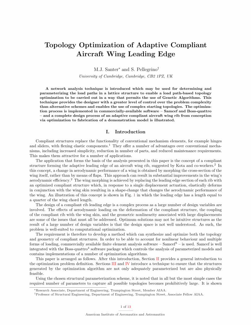
The application that forms the basis of the analysis presented in this paper is the concept of a compliantstructure forming the adaptive leading edge of an aircraft wing rib, suggested by Kota and co-workers.2 Inthis concept, a change in aerodynamic performance of a wing is obtained by morphing the cross-section of thewing itself, rather than by means of flaps. This approach can result in substantial improvements in the wing’saerodynamic efficiency.2 The wing morphing is achieved by replacing the leading edge section of each rib withan optimized compliant structure which, in response to a single displacement actuation, elastically deformsin conjunction with the wing skin resulting in a shape-change that changes the aerodynamic performance ofthe wing. An illustration of this concept is shown in Fig. 1 in which the leading edge has a length equal toa quarter of the wing chord length.
The design of a compliant rib leading edge is a complex process as a large number of design variables areinvolved. The effects of aerodynamic loading on the deformation of the compliant structure, the couplingof the compliant rib with the wing skin, and the geometric nonlinearity associated with large displacementsare some of the issues that must all be addressed. Optimum solutions may not be intuitive structures as theresult of a large number of design variables is that the design space is not well understood. As such, theproblem is well-suited to computational optimization.
The requirement is therefore to develop a method which can synthesize and optimize both the topologyand geometry of compliant structures. In order to be able to account for nonlinear behaviour and multipleforms of loading, commercially available finite element analysis software – Samcef3 – is used. Samcef is wellintegrated with the Boss-quattro4 software package which controls the analysis of parameterized models andcontains implementations of a number of optimization algorithms.
This paper is arranged as follows. After this introduction, Section II provides a general introduction tothe optimization problem definition. Sections III and IV introduce a technique to ensure that the structuresgenerated by the optimization algorithm are not only adequately parameterized but are also physicallyfeasible.
Using the chosen structural parameterization scheme, it is noted that in all but the most simple cases therequired number of parameters to capture all possible topologies becomes prohibitively large. It is shown
∗Research Associate, Department of Engineering, Trumpington Street, Member AIAA.†Professor of Structural Engineering, Department of Engineering, Trumpington Street, Associate Fellow AIAA.
1 of 13
American Institute of Aeronautics and Astronautics
compliant leading edge
shape change under actuation
displacement actuation
Figure 1. Compliant adaptive wing leading edge concept
how the load path selection method in Section III may be used to restrict the number of parameters whilststill ensuring the optimization algorithm is able to investigate as much of the design space as possible.
Section V illustrates how the generalized optimization process may be applied to the compliant wingleading edge problem, which results in the generation of a suitable structure. Modifications made to thisdesign to enable the construction of a physical demonstration model are described in Section VI, and sugges-tions are made for ways to extend the process for more complex problems in Section VII before conclusionsare drawn.
II. Optimization Problem Definition
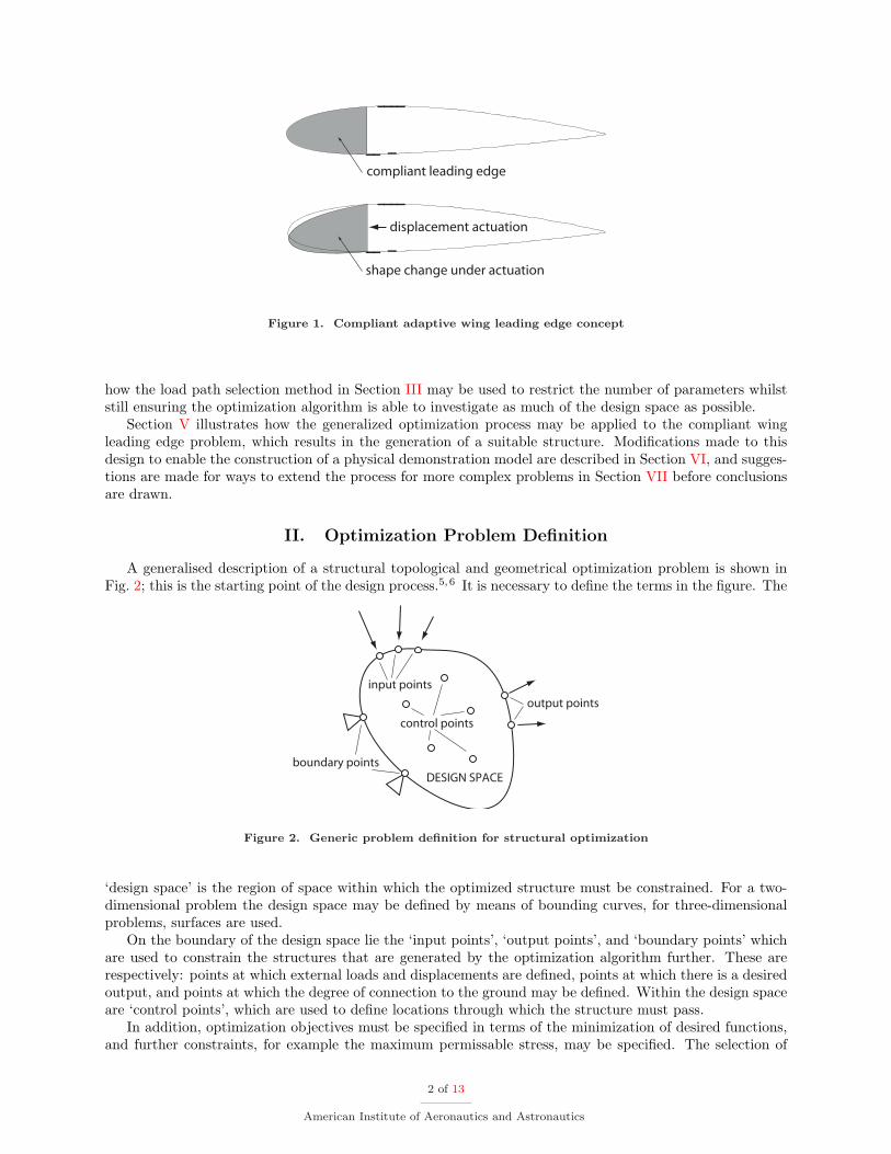
A generalised description of a structural topological and geometrical optimization problem is shown inFig. 2; this is the starting point of the design process.5,6 It is necessary to define the terms in the figure. The
input points
output points
boundary points
control points
DESIGN SPACE
Figure 2. Generic problem definition for structural optimization
‘design space’ is the region of space within which the optimized structure must be constrained. For a two-dimensional problem the design space may be defined by means of bounding curves, for three-dimensionalproblems, surfaces are used.
On the boundary of the design space lie the ‘input points’, ‘output points’, and ‘boundary points’ whichare used to constrain the structures that are generated by the optimization algorithm further. These arerespectively: points at which external loads and displacements are defined, points at which there is a desiredoutput, and points at which the degree of connection to the ground may be defined. Within the design spaceare ‘control points’, which are used to define locations through which the structure must pass.
In addition, optimization objectives must be specified in terms of the minimization of desired functions,and further constraints, for example the maximum permissable stress, may be specified. The selection of
2 of 13
American Institute of Aeronautics and Astronautics
these objectives and constraints is specific to the problem that is being considered.
A. Starting Point
Two primary techniques currently exist for providing a starting configuration for structural topology opti-mization. One is to fill the entire design space with material and permit the optimization algorithm to varythe material density.7 A variant of this technique maintains a constant material density but the materialis either present or absent. In this approach, it is necessary to implement techniques that avoid unrealisticdesigns when the material is alternately present and absent over small distances – a phenomenon known ascheckerboarding.
An advantage of this type of continuous optimization method is that the designer need not make anyassumptions when setting up the problem. A considerable disadvantage is that the final design must befurther subjected to a large amount of post-processing before it can be implemented as a physical structure.8
Such post-processing often requires a large amount of subjective decision on the part of the designer.An alternative approach is to specify an initial structural network, of given topology, and to search for
optimal structures whose topology is a subset of the original one.5,6 This means that the general structuralform is already specified at the beginning of the design process and therefore minimal post-processing isrequired to realize a structure designed by this method. This approach also enables the inclusion of complexstructural elements which would not be possible using the first approach. For example, the optimisationalgorithm can vary the connection type between adjacent members of the lattice between rigid and perfectly-hinged. A structure containing localized hinges may be used as a pseudo-rigid-body model, which may thenbe realized as a compliant structure.1
There are, however, some disadvantages to this approach. For example, all generated structures aredependent on the initially-defined parent structure and therefore the quality of the solution is dependenton the suitability of this initial choice. In addition, if parent topologies with a large number of componentsare used – a requirement if the design space is not well understood – the number of parameters required todefine the optimization can become prohibitively large.
Both of the above approaches have advantages but, because of the existing functionality of Samcef, itwas decided to limit the optimization to lattice structures (consisting of beam elements) and to provide aninitial topology as a starting point. Thus it was possible to utilize the parameterization facilities in Samcef15
and Boss-quattro to enable the optimization algorithm to generate subsets of the initial topology.
B. Load Path Parameterization
Having defined a parent structure consisting of a lattice of beam members, it is necessary to parameterizethis structure to enable the optimization algorithm to remove elements in order to derive new topologies.An intuitive approach would be to assign binary parameters to the existence of each member where ‘1’ cor-responds to ‘member exists’ and ‘0’ to ‘member does not exist’.5 This method of parameterization, however,leads to significant problems when it is combined with genetic search algorithms. Genetic Algorithms (GAs)are among the best tools for searching for optimal solutions when the design space is not well understood,as is usually the case for topological optimization.9,10 In addition, GAs have the advantage that they areless likely than gradient-based optimization algorithms to converge to local minima.
With the member parameterization scheme outlined above, GA iterations are very likely to generatedisconnected structures over the course of the optimization; for example, there may be no load path betweenan input point and the rest of the structure. This will cause the optimization to fail.
A solution to this problem6 is to adopt an alternative parameterization scheme which assigns a binaryparameter, not to individual members, but to sequences of members forming complete load paths. It canbe shown that a connected structure will be generated provided there is at least one load path betweeneach input and each output, each output and ground, and each input and ground. This is the topologyparameterization scheme that is adopted in this paper. However, the automatic generation of load paths fora given parent lattice is by no means straightforward and is discussed in Section III.
The final topology determined by the GA is dependent only on the load path parameterization. However,the GA may be used simultaneously to determine the optimum geometry of the lattice structure whichrequires additional parameterization. This may include, among other things, the beam member cross-sectionsand the control point location within the design space.
3 of 13
American Institute of Aeronautics and Astronautics
III. Load-Path Determination
The aim of this section is to present a systematic method for determining the load paths in a parentlattice, to enable a load path topology optimization.
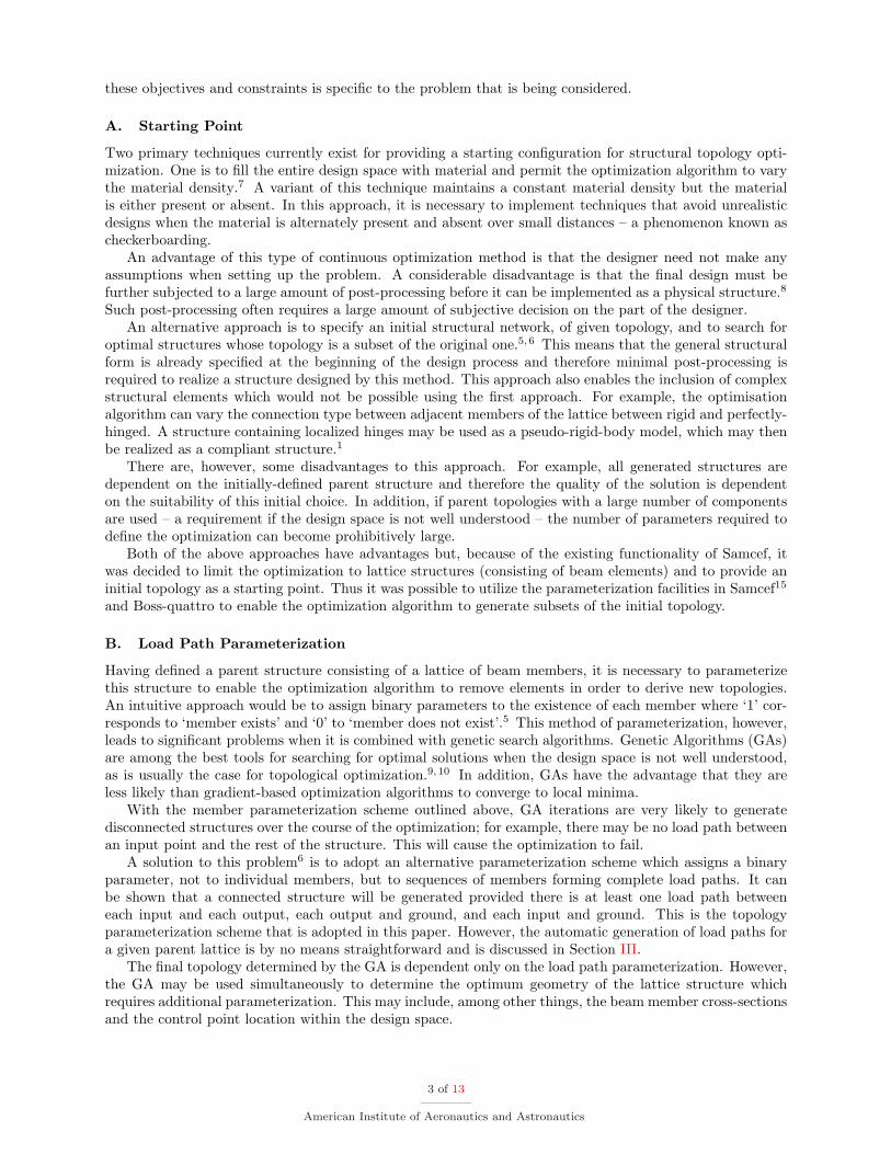
It is first useful to illustrate the effects of increasing the complexity of the parent lattice on the numberof possible load paths between two points. Figure 3 shows three lattice structures, each having the sameunit cell. In all cases, we are interested in the number of possible load paths between the start node (shownshaded) and the end node (shown with a thick border). It is worthwhile to define exactly what is meant bya load path in this context. A load path is a direct route by which force may be transferred between twochosen nodes in a structure. A load path may therefore contain no closed loops and hence the same nodemust not appear more than once in any path definition.
1 2
3 4
(a)
1 2 3
4 5 6
7 8 9
(b)
5 6 7
9 10 11
13 14 15
8
1 2 3 4
12
16
(c)
Figure 3. Lattices of increasing complexity
Figure 3(a) is the simplest lattice structure, consisting of 4 nodes and 5 members. It can readily be seenthat there are three load paths between node 1 and node 4: [1 4], [1 2 4], and [1 3 4]. At this scale of parentlattice, it makes no difference whether members or load paths are chosen to be parameterized. Figure 3(b)contains 9 nodes and 16 members. There can be shown to be 25 load paths between node 1 and node 9.Increasing the number of members by approximately three times results in a greater than eight-fold increasein the number of parameters required to represent the lattice fully if load path parameterization is used.Finally, Figure 3(c) contains 16 nodes and 33 members. The number of load paths between node 1 and node16 is 317. Thus, it is clear that, if load path representation is to be used, it is not practical to parameterizeall the possible load paths for all but the simplest parent lattice structures.
A. Load Path Selection
A possible solution to the rapid increase in the number of load paths with lattice complexity is simplyto limit the choice of parent structure to simple lattices, with only a few load paths. This is not a goodsolution, however, as limiting the complexity of the starting lattice limits the available topologies that maybe generated as subsets of this initial structure. In order to minimise the effect of initial lattice selection(which is a subjective choice made by the designer) it is desirable that a more complex parent lattice bechosen to maximise the number of available sub-topologies.
There are two issues which must be addressed when a complex initial lattice is chosen. First, it isnecessary to determine the number of load paths required to define the lattice, which may be very high.Second, it is necessary to restrict systematically the number of load paths that are parameterized in theanalysis.
A possible restriction method is to limit the number of members that may be linked to form a load path.8
There are many lattices, however, for which this is not a suitable option. For example, in the lattice shownin Fig. 3(c) the shortest load path contains 3 members, there are then 12 load paths with 4 members, and30 load paths with 5 members. Therefore, this technique provides the designer with limited means to setthe level of parameterization of the design problem.
The solution proposed in this paper is to parameterize the K shortest load paths, where K is an integervalue which may be defined by the designer. In the above example, if K is set to 20, the parameterized
4 of 13
American Institute of Aeronautics and Astronautics
load paths would include all the paths with 3 and 4 members, plus 7 load paths with 5 members. Whichof the 5-member load paths are chosen for parameterization is determined by the order in which they aredetermined by the algorithm which is used to search for the load paths.
B. K Shortest Simple Paths (KSSP)
In order to determine the K shortest load paths, network analysis theory is used. The parent lattice isrepresented as an undirected graph G = [E,N ] in which E is a set of all the edges in the graph (correspondingto the members in the parent lattice) and N is the set of nodes vi linked by the edges in the graph. Anundirected graph means that no distinction is made between the edges [vn, vm] and [vm, vn]. This is the casehere, as in a lattice structure this distinction is not needed. Additionally each edge has an associated cost crepresenting, their relative weighting. In this case, however, there is no physical relevance of the weight asonly the existence of a particular edge is of interest. Therefore they are equally weighted – in other wordsall edges have unit cost.
Having represented the parent lattice as a graph, the determination of the K shortest load paths maybe expressed as the well-known K shortest path (KSP) problem in network analysis. The solution of theKSP problem was first attempted in 1959 in order to analyse the traffic flow in Detroit.11 However KSPalgorithms permit paths with loops to be generated, but it has already been mentioned that in the presentcase the load paths should be loopless. In graph theory terminology this means that the paths must be‘simple’.
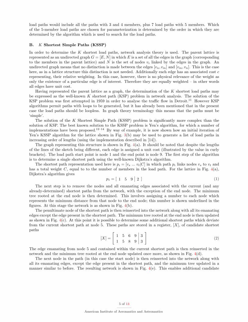
The solution of the K Shortest Simple Path (KSSP) problem is significantly more complex than thesolution of KSP. The best known solution to the KSSP problem is Yen’s algorithm, for which a number ofimplementations have been proposed.12–14 By way of example, it is now shown how an initial iteration ofYen’s KSSP algorithm for the lattice shown in Fig. 3(b) may be used to generate a list of load paths inincreasing order of lengths (using the implementation described in [14]).
The graph representing this structure is shown in Fig. 4(a). It should be noted that despite the lengthsof the lines of the sketch being different, each edge is assigned a unit cost (illustrated by the value in curlybrackets). The load path start point is node 1 and the end point is node 9. The first step of the algorithmis to determine a single shortest path using the well-known Dijkstra’s algorithm.
The shortest path representation used here is pi = [vs ... vt|C] in which path pi links nodes vs to vt andhas a total weight C, equal to to the number of members in the load path. For the lattice in Fig. 4(a),Dijkstra’s algorithm gives
p1 = [ 1 5 9 2 ] (1)
The next step is to remove the nodes and all emanating edges associated with the current (and anyalready-determined) shortest paths from the network, with the exception of the end node. The minimumtree rooted at the end node is then determined. This involves assigning a number to each node whichrepresents the minimum distance from that node to the end node; this number is shown underlined in thefigures. At this stage the network is as shown in Fig. 4(b).
The penultimate node of the shortest path is then reinserted into the network along with all its emanatingedges except the edge present in the shortest path. The minimum tree rooted at the end node is then updatedas shown in Fig. 4(c). At this point it is possible to determine some additional shortest paths which deviatefrom the current shortest path at node 5. These paths are stored in a register, [X], of candidate shortestpaths
[X] =
[1 5 6 9 31 5 8 9 3
](2)
The edge emanating from node 5 and contained within the current shortest path is then reinserted in thenetwork and the minimum tree rooted at the end node updated once more, as shown in Fig. 4(d).
The next node in the path (in this case the start node) is then reinserted into the network along withall its emanating edges, except the edge present in the shortest path, and the minimum tree updated in amanner similar to before. The resulting network is shown in Fig. 4(e). This enables additional candidate
5 of 13
American Institute of Aeronautics and Astronautics
1 2 3
4 5 6
7 8 9{1}
{1} {1}
{1} {1}
{1}
{1}
{1}
{1}
{1}
{1}
{1}
{1} {1}
{1} {1}
(a)
2 3
4 6
7 8 9
0
1
2
2
12
2
(b)
2 3
4 5 6
7 8 9
0
12
2
2
12
2
(c)
2 3
4 5 6
7 8 9
0
1
1
2
2
12
2
(d)
2 3
4
1
5 6
7 8 9
0
1
1
2
2
12
2
3
(e)
Figure 4. Illustration of a single iteration of Yen’s Algorithm
paths to be placed in [X] which deviate from the current shortest path at node 1 as follows
[X] =
1 5 6 9 31 5 8 9 31 2 5 9 31 2 6 9 31 4 5 9 31 4 8 9 3
(3)
At this point the next shortest path is selected from the array of candidate paths [X] as the path withthe smallest value of C. If however, many candidate paths have the same length (as may be seen in Eq. 3)then the first candidate path with the shortest length is selected and removed from [X]. In this case
p2 = [ 1 5 6 9 3 ] (4)
The process is continued until either [X] is empty or the number of shortest paths found is K. It canbe seen that this technique provides a systematic method for a designer to control precisely the level ofparameterization of the parent lattice, and, perhaps equally important, to determine how many load pathsare not included in an optimization and consequently how many potential topologies are being neglected.
IV. Feasible Structure Generation
It is clearly desirable that the optimization process results in an optimum structure which not onlysatisfies the imposed constraints but is also feasible to construct. Ensuring structural feasibility is, however,often neglected in the implementation of lattice structure topology optimization.
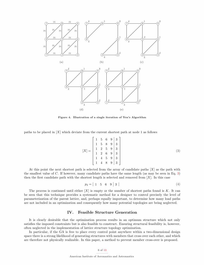
In particular, if the GA is free to place every control point anywhere within a two-dimensional designspace there is a strong likelihood of generating structures with members that cross over each other, and whichare therefore not physically realizable. In this paper, a method to prevent member cross-over is proposed.
6 of 13
American Institute of Aeronautics and Astronautics
member cross-over
(a) Cross-over illustration
BOUNDARY DOMAIN
Boundary nodes
r2
r3
r5
r4
r1
circle with minimum
displacement radius
(b) Nodal boundary domain
Figure 5. Member cross-over avoidance
To a certain extent, the possibility of member cross-over can be reduced by careful choice of parentlattices that do not have crossing members. Using this criterion, all the lattices examined in Fig. 3 wouldbe suitable candidates. However, if the control points may be placed anywhere within the design space sucha lattice may still result in unfeasible structures. For example, if in Fig. 5(a) the shaded node is movedas shown by the optimization algorithm, while all other nodes remain in their original location, a membercross-over occurs.
A way of removing the possibility of member cross-over is to restrict the movement of control pointswithin the design space. The technique proposed here is to assign all non-fixed nodes a series of boundarynodes which define a polygonal boundary domain, as shown in Fig. 5(b).
Each control point is assigned two geometric parameters which determine their displacement, in polarcoordinates, from a known datum point. One geometry parameter determines the angle, and the otherdetermines the fraction of a maximum permitted radius r. This radius is determined from the boundarynodes.
In Fig. 5(b) the control point is shown as a white circle. The boundary nodes, shown as black circles, aredefined as the nodes to which there is a direct edge connection (not shown in the figure) from the controlpoint. The boundary nodes form a closed polygon around the control point – the boundary domain. Theminimum perpendicular distance (r = min(r1, r2, r3, r4, r5)) from the control point to each of the boundarydomain edges is defined as the maximum allowable radius of displacement that the control point may undergo.By restricting the geometric changes of the control point locations in this way, the possibility of membercross-over is removed.
V. Optimization of Wing Leading Edge
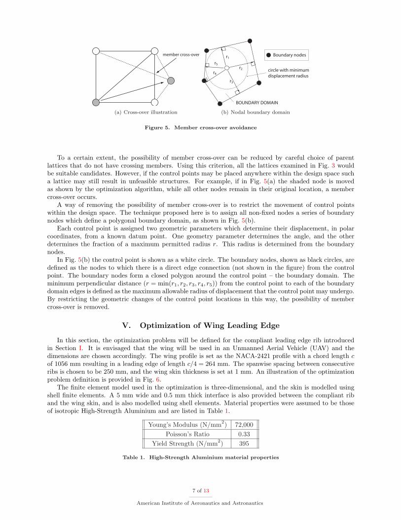
In this section, the optimization problem will be defined for the compliant leading edge rib introducedin Section I. It is envisaged that the wing will be used in an Unmanned Aerial Vehicle (UAV) and thedimensions are chosen accordingly. The wing profile is set as the NACA-2421 profile with a chord length cof 1056 mm resulting in a leading edge of length c/4 = 264 mm. The spanwise spacing between consecutiveribs is chosen to be 250 mm, and the wing skin thickness is set at 1 mm. An illustration of the optimizationproblem definition is provided in Fig. 6.
The finite element model used in the optimization is three-dimensional, and the skin is modelled usingshell finite elements. A 5 mm wide and 0.5 mm thick interface is also provided between the compliant riband the wing skin, and is also modelled using shell elements. Material properties were assumed to be thoseof isotropic High-Strength Aluminium and are listed in Table 1.
Young’s Modulus (N/mm2) 72,000Poisson’s Ratio 0.33
Yield Strength (N/mm2) 395
Table 1. High-Strength Aluminium material properties
7 of 13
American Institute of Aeronautics and Astronautics
250 mm
c/4
skin
c
A
C
D
F
B
x
y
z
output
points
E
5 mm
rib plane
Figure 6. Adaptive leading edge optimization problem definition
A. Optimization Objective Functions
There are several optimization objectives that may be used, including minimizing the peak stress in thestructure under actuation and minimizing the mass of the compliant rib. Also, the ‘model complexity’ canbe minimized. This is a term which is related to minimizing the mass but is extended to provide a metricrelated to ease of construction.
If i load paths (p) are parameterized (with ‘1’ corresponding to ‘load path exists’) then the modelcomplexity may be defined as
model complexity =∑
i
pi (5)
However, if the connection type (c) is also parameterized (with ‘1’ corresponding to ‘hinge connection’) thenthe definition may be extended to
model complexity =∑
i
pi +∑
j
cj (6)
in which j is the total number of connection parameters. This is an advantageous optimization objective, aspost-processing is required to implement rotational hinges as living hinges, which it is desirable to reduce.The form and number of objective functions is at the discretion of the designer. It has been observed,however, that the use of fewer objectives with more simple definitions substantially improves optimizationconvergence rates at the expense of increasing the post-processing requirements.
The primary objective function for the optimization, however, is the root-mean-square (rms) error of theactual deflection d measured at the output point under actuation when compared to the desired deflectionδ. If there are i output points the rms error objective function is defined as
rms error =
√∑i(di − δi)2
i(7)
For the compliant rib leading edge, the desired shape change is specified in terms of the vertical dis-placement of twenty points on the wing skin, arranged in two rows of ten (see the output points shown inFig. 6). The reason for the two rows is to ensure there is no substantial variation of deflection in the spanwisedirection. The desired shape change is equivalent to the vertical deflection that would result if the leadingedge were rotated by 5◦ downwards
B. Loads and Boundary Conditions
The FE model is fully-clamped at the interface between the leading edge and the rest of the wing. In Fig. 6this corresponds to the lines CD and EF. The edges CE and DF are restrained against spanwise (z-axis)movement but are free to translate in the xy-plane.
8 of 13
American Institute of Aeronautics and Astronautics
A single displacement actuation is applied to the compliant rib structure at along line AB. However,loading is also applied to the wing skin elements to represent the aerodynamic pressure loading that thewing is subjected to during flight. This pressure loading is calculated assuming a 260 kts (134 m/s) air speedat sea level and a 5◦ angle of attack. Inviscid flow is also assumed.
This is not an aeroelastic analysis – no account is taken of the change in pressure loading due to the changein wing profile under actuation – but it ensures that the compliant structure generated by the optimizationalgorithm accounts for the presence of an aerodynamic loading which, if not exact, will be of the correctorder of magnitude.
C. Compliant Rib Parameterization
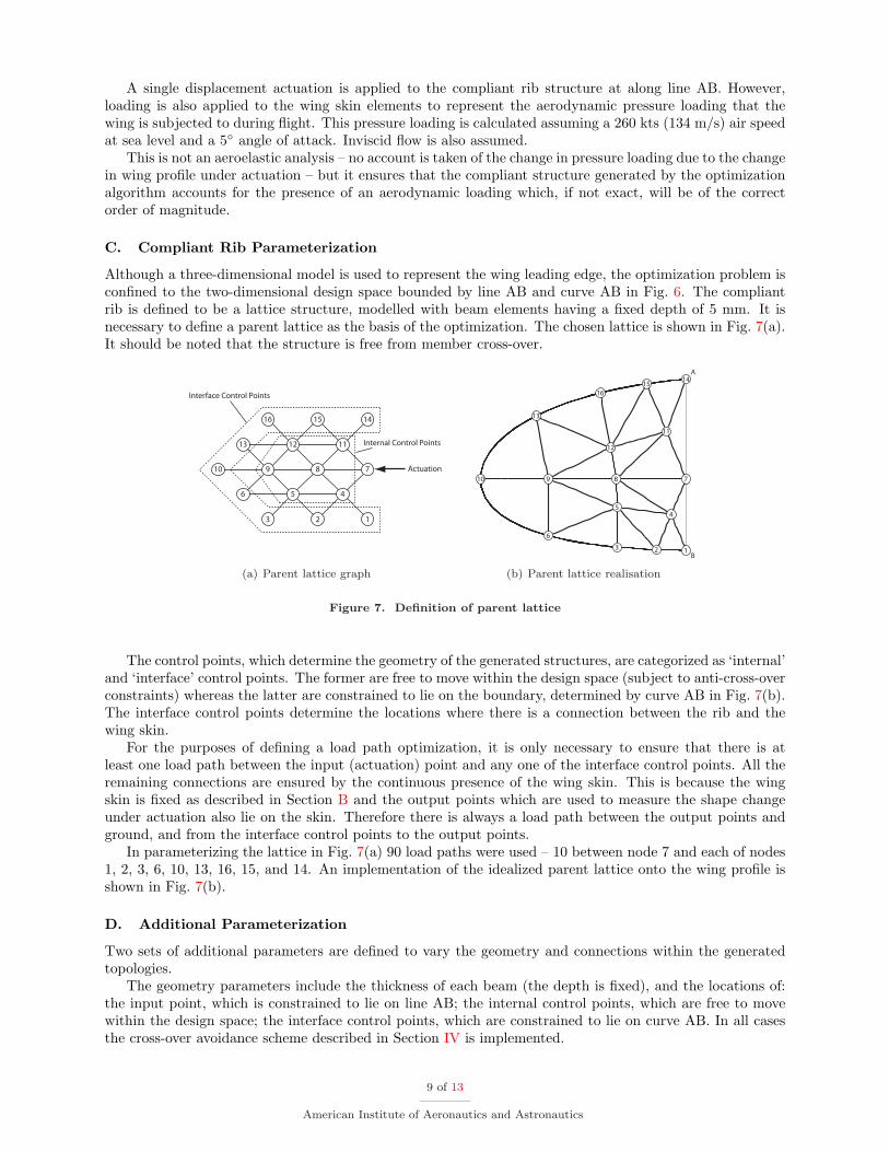
Although a three-dimensional model is used to represent the wing leading edge, the optimization problem isconfined to the two-dimensional design space bounded by line AB and curve AB in Fig. 6. The compliantrib is defined to be a lattice structure, modelled with beam elements having a fixed depth of 5 mm. It isnecessary to define a parent lattice as the basis of the optimization. The chosen lattice is shown in Fig. 7(a).It should be noted that the structure is free from member cross-over.
123
456
789
111213
10
141516
Interface Control Points
Actuation
Internal Control Points
(a) Parent lattice graph
123
4
5
6
78910
11
12
13
16
1514
A
B
(b) Parent lattice realisation
Figure 7. Definition of parent lattice
The control points, which determine the geometry of the generated structures, are categorized as ‘internal’and ‘interface’ control points. The former are free to move within the design space (subject to anti-cross-overconstraints) whereas the latter are constrained to lie on the boundary, determined by curve AB in Fig. 7(b).The interface control points determine the locations where there is a connection between the rib and thewing skin.
For the purposes of defining a load path optimization, it is only necessary to ensure that there is atleast one load path between the input (actuation) point and any one of the interface control points. All theremaining connections are ensured by the continuous presence of the wing skin. This is because the wingskin is fixed as described in Section B and the output points which are used to measure the shape changeunder actuation also lie on the skin. Therefore there is always a load path between the output points andground, and from the interface control points to the output points.
In parameterizing the lattice in Fig. 7(a) 90 load paths were used – 10 between node 7 and each of nodes1, 2, 3, 6, 10, 13, 16, 15, and 14. An implementation of the idealized parent lattice onto the wing profile isshown in Fig. 7(b).
D. Additional Parameterization
Two sets of additional parameters are defined to vary the geometry and connections within the generatedtopologies.
The geometry parameters include the thickness of each beam (the depth is fixed), and the locations of:the input point, which is constrained to lie on line AB; the internal control points, which are free to movewithin the design space; the interface control points, which are constrained to lie on curve AB. In all casesthe cross-over avoidance scheme described in Section IV is implemented.
9 of 13
American Institute of Aeronautics and Astronautics
The connection parameter determines the connection type between adjacent members. These may beeither rigid or perfect hinge connections. This enables the optimization to generate structures with bothdistributed and localized compliance.
E. Optimization Settings
The load path optimization was implemented using Samcef and Boss-quattro Full details may be found in[15], and only a brief summary is provided here.
A population size of 10 individuals is specified for the GA optimization. In each iteration there is a 90%probability of cross-over and a 1% probability of mutation. Individuals are selected for suitability by meansof a tournament.
F. Simplified Optimization Results
An initial optimization was carried out using the minimization of the rms-error function (as defined in Eq. 7)and the model complexity (as defined in Eq. 5) as objective functions. All connections between adjacentmembers were defined as rigid, with the result that structures with only distributed compliance could begenerated by the GA. The peak stress was not constrained.
An initial investigation was carried out to determine whether geometrically-nonlinear analysis was nec-essary. Linear analysis was found to be sufficient to model the deflections resulting from the actuation, andlinear analysis was therefore used in the optimization. It is, however, necessary to carry out a geometrically-nonlinear arc-length analysis of the final optimized structure to ensure that there is no buckling of themembers under actuation.
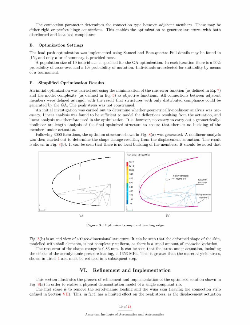
Following 3000 iterations, the optimum structure shown in Fig. 8(a) was generated. A nonlinear analysiswas then carried out to determine the shape change resulting from the displacement actuation. The resultis shown in Fig. 8(b). It can be seen that there is no local buckling of the members. It should be noted that
X
Y
Z
(a)
0
135
271
406
541
677
812
947
1083
1218
1353
X
Y
Z
von Mises Stress (MPa)
actuation
(10 mm)
highly-stressed
member 1
highly-stressed
member 2
(b)
Figure 8. Optimized compliant leading edge
Fig. 8(b) is an end view of a three-dimensional structure. It can be seen that the deformed shape of the skin,modelled with shall elements, is not completely uniform, as there is a small amount of spanwise variation.
The rms error of the shape change is 0.83 mm. It can be seen that the stress under actuation, includingthe effects of the aerodynamic pressure loading, is 1353 MPa. This is greater than the material yield stress,shown in Table 1 and must be reduced in a subsequent step.
VI. Refinement and Implementation
This section illustrates the process of refinement and implementation of the optimized solution shown inFig. 8(a) in order to realize a physical demonstration model of a single compliant rib.
The first stage is to remove the aerodynamic loading and the wing skin (leaving the connection stripdefined in Section VII). This, in fact, has a limited effect on the peak stress, as the displacement actuation
10 of 13
American Institute of Aeronautics and Astronautics
has a significantly greater effect on the stresses than the aerodynamic loading, and the highest stresses arein the rib members. The peak stresses are concentrated in the two members labelled as highly-stressed inFig. 8(b). They are reduced in two different ways, as follows.
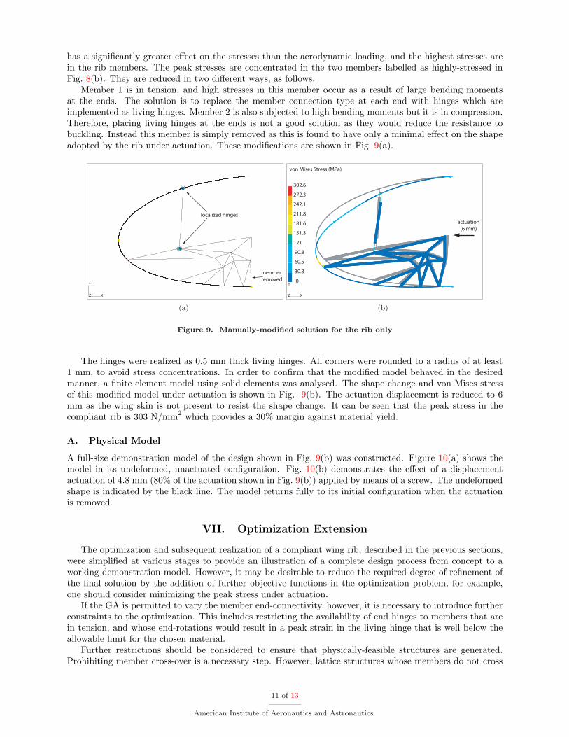
Member 1 is in tension, and high stresses in this member occur as a result of large bending momentsat the ends. The solution is to replace the member connection type at each end with hinges which areimplemented as living hinges. Member 2 is also subjected to high bending moments but it is in compression.Therefore, placing living hinges at the ends is not a good solution as they would reduce the resistance tobuckling. Instead this member is simply removed as this is found to have only a minimal effect on the shapeadopted by the rib under actuation. These modifications are shown in Fig. 9(a).
X
Y
Z
localized hinges
member
removed
(a)
0
30.3
60.5
90.8
121
151.3
181.6
211.8
242.1
272.3
302.6
X
Y
Z
von Mises Stress (MPa)
actuation
(6 mm)
(b)
Figure 9. Manually-modified solution for the rib only
The hinges were realized as 0.5 mm thick living hinges. All corners were rounded to a radius of at least1 mm, to avoid stress concentrations. In order to confirm that the modified model behaved in the desiredmanner, a finite element model using solid elements was analysed. The shape change and von Mises stressof this modified model under actuation is shown in Fig. 9(b). The actuation displacement is reduced to 6mm as the wing skin is not present to resist the shape change. It can be seen that the peak stress in thecompliant rib is 303 N/mm2 which provides a 30% margin against material yield.
A. Physical Model
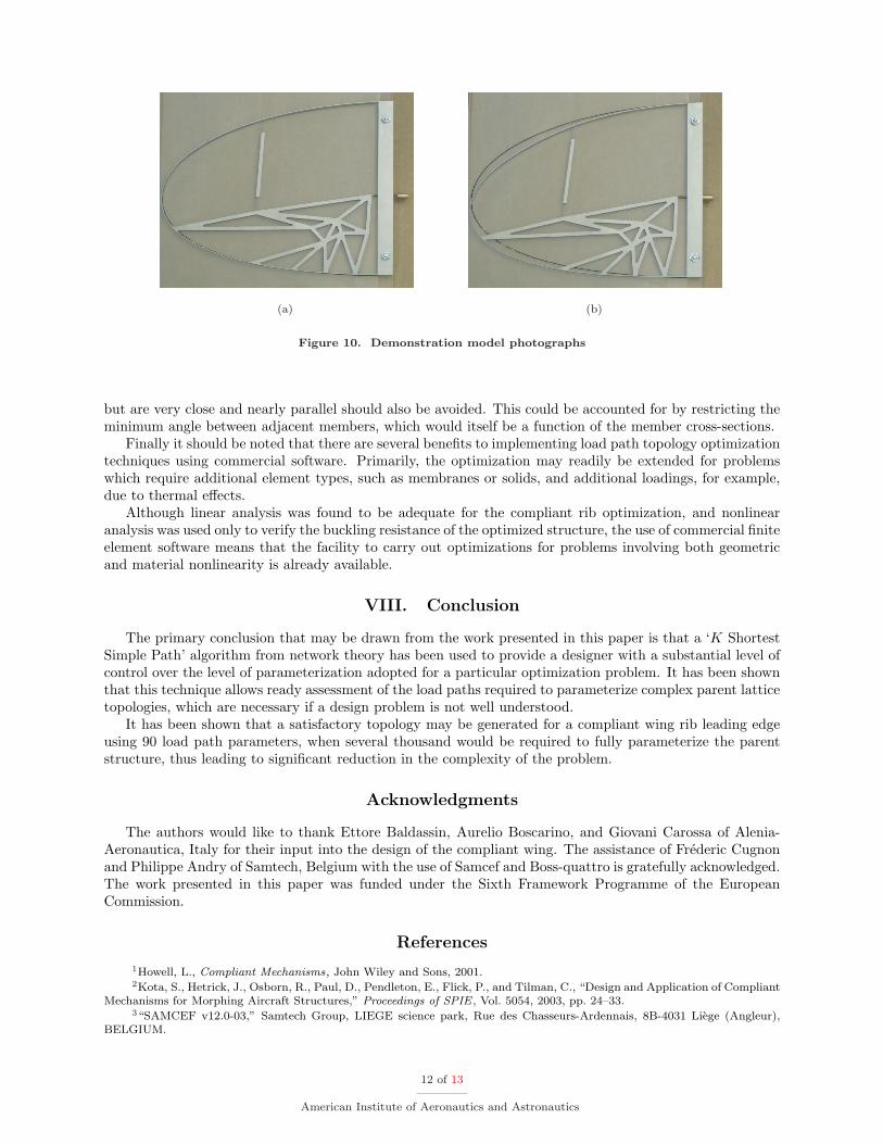
A full-size demonstration model of the design shown in Fig. 9(b) was constructed. Figure 10(a) shows themodel in its undeformed, unactuated configuration. Fig. 10(b) demonstrates the effect of a displacementactuation of 4.8 mm (80% of the actuation shown in Fig. 9(b)) applied by means of a screw. The undeformedshape is indicated by the black line. The model returns fully to its initial configuration when the actuationis removed.
VII. Optimization Extension
The optimization and subsequent realization of a compliant wing rib, described in the previous sections,were simplified at various stages to provide an illustration of a complete design process from concept to aworking demonstration model. However, it may be desirable to reduce the required degree of refinement ofthe final solution by the addition of further objective functions in the optimization problem, for example,one should consider minimizing the peak stress under actuation.
If the GA is permitted to vary the member end-connectivity, however, it is necessary to introduce furtherconstraints to the optimization. This includes restricting the availability of end hinges to members that arein tension, and whose end-rotations would result in a peak strain in the living hinge that is well below theallowable limit for the chosen material.
Further restrictions should be considered to ensure that physically-feasible structures are generated.Prohibiting member cross-over is a necessary step. However, lattice structures whose members do not cross
11 of 13
American Institute of Aeronautics and Astronautics
(a) (b)
Figure 10. Demonstration model photographs
but are very close and nearly parallel should also be avoided. This could be accounted for by restricting theminimum angle between adjacent members, which would itself be a function of the member cross-sections.
Finally it should be noted that there are several benefits to implementing load path topology optimizationtechniques using commercial software. Primarily, the optimization may readily be extended for problemswhich require additional element types, such as membranes or solids, and additional loadings, for example,due to thermal effects.
Although linear analysis was found to be adequate for the compliant rib optimization, and nonlinearanalysis was used only to verify the buckling resistance of the optimized structure, the use of commercial finiteelement software means that the facility to carry out optimizations for problems involving both geometricand material nonlinearity is already available.
VIII. Conclusion
The primary conclusion that may be drawn from the work presented in this paper is that a ‘K ShortestSimple Path’ algorithm from network theory has been used to provide a designer with a substantial level ofcontrol over the level of parameterization adopted for a particular optimization problem. It has been shownthat this technique allows ready assessment of the load paths required to parameterize complex parent latticetopologies, which are necessary if a design problem is not well understood.
It has been shown that a satisfactory topology may be generated for a compliant wing rib leading edgeusing 90 load path parameters, when several thousand would be required to fully parameterize the parentstructure, thus leading to significant reduction in the complexity of the problem.
Acknowledgments
The authors would like to thank Ettore Baldassin, Aurelio Boscarino, and Giovani Carossa of Alenia-Aeronautica, Italy for their input into the design of the compliant wing. The assistance of Frederic Cugnonand Philippe Andry of Samtech, Belgium with the use of Samcef and Boss-quattro is gratefully acknowledged.The work presented in this paper was funded under the Sixth Framework Programme of the EuropeanCommission.
References
1Howell, L., Compliant Mechanisms, John Wiley and Sons, 2001.2Kota, S., Hetrick, J., Osborn, R., Paul, D., Pendleton, E., Flick, P., and Tilman, C., “Design and Application of Compliant
Mechanisms for Morphing Aircraft Structures,” Proceedings of SPIE , Vol. 5054, 2003, pp. 24–33.3“SAMCEF v12.0-03,” Samtech Group, LIEGE science park, Rue des Chasseurs-Ardennais, 8B-4031 Liege (Angleur),
BELGIUM.
12 of 13
American Institute of Aeronautics and Astronautics
4“BOSS-quattro v6.0-01,” Samtech Group, LIEGE science park, Rue des Chasseurs-Ardennais, 8B-4031 Liege (Angleur),BELGIUM.
5Lu, K.-J. and Kota, S., “Design of Compliant Mechanisms for Morphing Structural Shapes,” Journal of IntelligentMaterial Systems and Structures, Vol. 14, 2003, pp. 379–391.
6Lu, K.-J. and Kota, S., “An Effective Method of Synthesizing Compliant Adaptive Structures using Load Path Repre-sentation,” Journal of Intelligent Material Systems and Structures, Vol. 16, 2004, pp. 307–317.
7Pedersen, C., Buhl, T., and Sigmund, O., “Topology Synthesis of Large-Displacement Compliant Mechanisms,” Interna-tion Journal for Numerical Methods in Engineering, Vol. 50, 2001, pp. 2683–2705.
8Lu, K.-J. and Kota, S., “Topology and Dimensional Synthesis of Compliant Mechanisms using Discrete Optimization,”Journal of Mechanical Design, Vol. 128, 2006, pp. 1080–1091.
9Ponterosso, P. and Fox, D., “Going Organic: Using Evolution in Civils Design,” Proceedings of ICE , Vol. 160, 2007,pp. 43–48.
10Forrest, S., “Genetic Algorithms: Principles of Natural Selection applied to Computation,” Science, Vol. 261, 1993,pp. 872–878.
11Hoffman, W. and Pavley, R., “A Method for the solution of the Nth Best Path Problem,” Journal of Association ofComputing Machinery, Vol. 6, 1959, pp. 506–514.
12Clarke, S., Krikorian, A., and Rausen, J., “Computing the N Best Loopless Paths in a Network,” Journal of Society ofIndustrial and Applied Mathematics, Vol. 11, 1963, pp. 1096–1102.
13Hadjiconstantinou, E. and Christofides, N., “An Efficient Implementation of an Algorithm for Finding K Shortest SimplePaths,” Networks, Vol. 34, 1999, pp. 88–101.
14Martins, E. and Pascoal, M., “A new implementation of Yen’s ranking loopless paths algorithm,” Submitted, 2000. URL(http://www.mat.uc.pt/eqvm/cientificos/investigacao/Artigos/new yen.ps.gz).
15Santer, M. and Pellegrino, S., “Implementation of Load-Path Topology Optimisation in Samcef for the Generation ofCompliant Structures,” Proceedings of the 10th Samtech Users’ Conference, 2007.
13 of 13
American Institute of Aeronautics and Astronautics