Embed Size (px)
Citation preview
Calhoun: The NPS Institutional Archive
Theses and Dissertations Thesis Collection
1992
Evaluation and repair of concrete slabs
Siegfried, Robert W.
Gainesville, Florida: University of Florida
http://hdl.handle.net/10945/23889


EVALUATION AND REPAIR OFCONCRETE SLABS
By
ROBERT W. SIEGFRIED
A REPORT PRESENTED TO THE GRADUATE COMMITTEEOF THE DEPARTMENT OF CIVIL ENGINEERING INPARTIAL FULFILLMENT OF THE REQUIREMENTSFOR THE DEGREE OF MASTER OF ENGINEERING
UNIVERSITY OF FLORIDA
SUMMER 1992
T260674


EVALUATION AND REPAIR OFCONCRETE SLABS
By
ROBERT W. SIEGFRIEDr
A REPORT PRESENTED TO THE GRADUATE COMMITTEEOF THE DEPARTMENT OF CIVIL ENGINEERING IN
PARTIAL FULFILLMENT OF THE REQUIREMENTSFOR THE DEGREE OF MASTER OF ENGINEERING
UNIVERSITY OF FLORIDA
SUMMER 1992


To Sally, my wife and my friend, your sacrifice and
commitment to our family made it possible to meet this goal in
my life. Your company, support, and love made it a lot
easier. And to my children, Amie and William, your love and
your smiles make it all worthwhile.


ACKNOWLEDGEMENTS
I would like to express my appreciation to Dr. Ronald
Cook for his advice and suggestions, and for providing
outstanding review during the writing of this report. Special
thanks are extended to Dr. Zohar Herbsman and Dr. Byron Ruth
for their participation on my supervisory committee.
1
1


TABLE OF CONTENTS
DEDICATION i
ACKNOWLEDGEMENTS i i
LIST OF TABLES v
LIST OF FIGURES vi
CHAPTER I INTRODUCTION 1
1 . 1 General 1
1 .2 Background 1
1.3 Objectives 3
1 .k Scope 3
1 .5 Report Overview k
CHAPTER II RECOGNIZING CONCRETE PROBLEMS 6
2.1 Overview 6
2.2 General Problem Causes 7
2.2.1 Defects 7
2.2.2 Damage 8
2.2.3 Deterioration 8
2.3 Problem Types 9
2.3.1 Cracking 10
2.3.1.1 Crazing 11
2.3.1.2 Early Cracking \k2.3.1.3 Post-hardening Cracking .... 19
2.3.2 Surface defects 21
2.3.2.1 Scaling 21
2.3.2.2 Dusting 222.3.2.3 Blisters 232.3.2.4 Spalling 252.3.2.5 Popouts 252.3.2.6 Honeycombing 27
ill


2.3.3 Joint deficiencies 28
CHAPTER III GENERAL REPAIR PRINCIPLES 31
3.1 Overview 31
3.2 Evaluating Concrete Problems 31
3.3 Choosing a Repair Method 333.4 Choosing a Repair Material 35
3.4. 1 Material Types 363.4.2 Material Properties 37
3.5 Preparations for Repair 39
CHAPTER IV MATERIALS AND METHODS OF REPAIR 4 1
4.1 Overview 41
4.2 Materials 4 1
4.2.1 Cement itious Materials 424.2.2 Polymers 4 3
4.2.2.1 Res i ns/Polymer s/Adhes i ves ... 444.2.2.2 Polymer Concrete 47
4.3 Methods of Repair 50
4.3.1 Patching and Small Scale Repairs ... 514.3.2 Concrete Replacement 534.3.3 Repairs to Cracks 54
4.3.3.2 Epoxy Injection Repairs .... 56
4.3.4 Repairs to Joints 59
CHAPTER V CONCLUSION AND RECOMMENDATIONS 61
5.1 Conclusion 61
5.2 Recommendations 63
APPENDIX A - Guide for Making a Condition Survey ofConcrete Pavements (ACI 201.3R-86) 66
APPENDIX B - Identification and Control ofConsolidation-related Defects (ACI 309.2R-82) . . 89
APPENDIX C - Causes, Evaluation, and Repair of Cracksin Concrete Structures (ACI 224.1R-89) 101
1 v


LIST OF TABLES
Table 4.1 Grades and Classes of Type I Epoxies .... 46
Table 4.2 Extra Material Cost/Sq. Foot of Overlay . . 50
Table 4.3 Tolerable Crack Widths 55


LIST OF FIGURES
Figure 2.1 Crazing Concrete Surface 12
Figure 2.2 Map Cracking 12
Figure 2.3 Typical plastic shrinkage cracking 16
Figure 2.k Severe Plastic shrinkage cracks in a floor
slab 16
Figure 2.5 Shifting Form Crack 17
Figure 2.6 Obstructed settlement crack. 18
Figure 2.7 Restraint causes drying shrinkage cracks . 19
Figure 2.8 Typical drying shrinkage cracks 20
Figure 2.9 Scaled concrete 22
Figure 2.10 Concrete blisters 23
Figure 2.11 Concrete blister formation 2k
Figure 2.12 Typical popouts 26
Figure 2.13 Surface Honeycombing 27
Figure 2.\k Honeycombing within concrete 28
Figure 2.15 Causes of joint edge spalling 30
v 1


CHAPTER I
INTRODUCTION
1 .
1
General
Concrete is normally thought of as a solid, reliable,
and mostly maintenance- free construction material. Indeed, if
properly designed, produced and placed, concrete will provide
long service with little maintenance. But, all structures
inevitably age and deteriorate, regardless of how well they
were designed and built. In today's economic climate, the
demand for new construction has diminished significantly.
Owners are looking for ways to cut costs, and often end up
renovating more and building less. In this environment,
construction professionals must be thoroughly knowledgeable of
how to properly renovate and repair concrete structures, and
how to ensure the new facilities they build will remain
durable, and not deteriorate prematurely .
1 .
2
Background
Most concrete structures are rarely beyond repair, and
there is nearly an unlimited selection of repair products and
processes available to restore them. Epoxies, acrylics,
polyesters, cementitious grouts, mortars, and shotcrete mixes
can all be used for concrete repair. These products are sold
1


in a wide variety of packages and price ranges, and each
product has its own specific features, benefits, and uses.
Accordingly, repair contractors are faced with the
difficult decision of which product to use for the specific
problem at hand. Cost cannot, and should not, be the only
consideration. Factors concerning the actual concrete to be
repaired, such as its location in the structure, the
environment to which it is exposed, and the length of time the
repair must last, must be considered. In addition, the repair
product itself must be taken into account. "Critical factors
such as bonding capability, shrinkage, expansion, strength,
thermal compatibility, ease of application, waterproofing,
freeze/thaw and abrasion resistance" [1:151] of the repair
material must be considered.
Selection of the proper repair method and material
further depends on the type of problem to be corrected, and
its cause. Concrete problems are classified, according to
their root cause as: deterioration, damage, and defects.
These major classifications can be further broken down for
specific causes. For example, "deterioration of concrete in
service may be the result of a variety of physical and
chemical processes, such as attack by acids, sulfates, or
alkalis, alkali-aggregate reactions, freeze-thaw cycles, etc."
[2: 186]
In short, the contractor contemplating a concrete repair
must consider many factors to ensure a durable and strong

repair. The specific problem, its underlying cause, the
importance of the repair, and the benefits and costs of
specific repair methods/materials, must all be determined and
addressed
.
1 . 3 Ob j ect i ves
The purpose of this report is to review the different
types and causes of concrete failure, and to outline those
factors which a contractor must consider when selecting a
repair strategy. The report will further discuss how to
recognize, evaluate, and repair common concrete problems which
occur during construction, or as a direct result of improper
construction practices. The report will also outline how
these common problems can be avoided or prevented in the first
place
.
1
.
k Scope
When repairing a concrete structure, the various elements
of that structure each require special consideration. To
present information on all of the different types of problems,
for each of the these structural elements is beyond the scope
of one paper. This report will concentrate on those problems
typically encountered with concrete slabs. The report will
summarize the current information on recognizing, repairing,
and preventing concrete damage, defects, and deterioration to
slabs. Emphasis will be accorded to those problems which


occur during construction, or are caused by the construction
itself. Since deterioration normally occurs over a long
period of time, and; therefore, is not an immediate concern of
the construction contractor, its evaluation and repair will
not be discussed in detail.
1 . 5 Report Overview
Chapter two describes the differences between the three
classes of concrete problems; damage, defects, and
deterioration. The chapter describes in detail the typical
problems encountered during, and shortly after construction of
concrete slabs, and provides parameters which a contractor can
use to identify these problems, and their causes.
Simple recognition of a problem is not sufficient to
ensure a proper, long-lasting repair. The cause of the
problem also plays a significant role in determining the
proper repair method. Chapter three introduces the condition
survey as a means of evaluating the causes of the typical
problems discussed in chapter two.
The heart of the report is in chapter four. This chapter
outlines the repair materials and methods available today, and
evaluates which are best for repairing construction related
problems. Chapter four will also provide general recommended
procedures for each of the repair techniques.
Perhaps the requirement for concrete repair may never be
eliminated; but, through sound construction practices


potential problems can be greatly reduced. Chapter five
provides recommendations and conclusions concerning concrete
repairs and ways for contractors to avoid or prevent the most
common problems encountered with slabs. Incorporating these
comments into daily construction practice will help to reduce
common slab construction problems, and provide the wherewithal
to correct those which do occur.


CHAPTER I I
RECOGNIZING CONCRETE PROBLEMS
2 . 1 Over v i ew
Problems with concrete occur in many forms, and as a
result of a wide variety of causes. Some of these problems
occur long after the contractor has completed construction and
left the jobsite. Still others occur while the structure is
being built, or soon after its completion. Several of these
problems are a direct result of the construction practices
used during the construction. "Many of the problems evident
in hardened concrete are created in the forming, placing, and
finishing of the concrete in the plastic stage. Some flaws
are noticeable during, or shortly after, the initial set;
others appear within a few days after placement." [3:69]
Early identification of concrete flaws is the first step
to successful repair and prevention of further deterioration.
To properly identify and repair a particular problem, a
contractor must have knowledge of the cause and inherent
characteristics of that problem. This chapter will provide a
synopsis of the general causes of problems in concrete slabs,
outline the common problem types encountered in slabs and
their specific cause, and provide details concerning the
appearance of these problems so they may be easily identified.
6


2 . 2 General Problem Causes
Over its lifetime, a concrete structure may exhibit
myriad problems. These problems can generally be categorized
according to their cause as: defects, damage, or
deterioration. There are no strict guidelines for assigning
a specific problem to one of the categories, as some concrete
problems may be caused by any one of the three. Spalls, for
instance, may be a result of corros ion- induced deterioration,
impact damage, or a material defect. Concrete problems in any
of the three categories may be caused by construction
practice, but normally only defects and damage are readily
apparent during, or soon after, construction.
2.2.1 Defects
A defect is an imperfection or fault which may limit or
prohibit a structure's capability to perform its intended
function. A defect may be as simple as a stain on the
surface, or may be a much more serious structural flaw.
Defects normally manifest themselves early in a structure's
life. They are most commonly attributed to: wrong assumptions
or errors in the design, improper material placement or
construction practices, and deficient materials. Cracking,
dusting, scaling, popouts, and honeycombing are common
examples of concrete defects.


2.2.2 Damage
All structures are subject to damage that may preclude,
or inhibit them from performing their intended function.
Concrete structures, in particular, are exposed to weathering,
chemical reactions within the concrete itself, and chemical or
mechanical attack. Good, durable concrete is resistant to
most routine exposures. For concrete which may be exposed to
more severe conditions, additional protection can be provided.
However, no protection is absolute, and damage does occur.
Although some damage occurs over the long-term, the
constructor is more concerned with those damages which occur
abruptly, or as the result of a specific event. Specific
examples of these types of damage causing events include
fires, earthquakes, impacts, abrasion, and overloads. The
extent of damage from these causes will of course depend on
the severity of the cause, and the strength of the affected
member. Damage can range from small cracks to total failure.
"Based on the capacity of the member and the nature and
severity of the damage, its impact or significance will be
more or less debilitating." [11:4] Regardless of the extent
of damage, the concrete should be repaired immediately to
prevent further damage or deterioration.
2.2.3 Deter i orat i on
Deterioration is defined as "any adverse change of normal
mechanical, physical and chemical properties either on the
8


surface or in the whole body of concrete generally through
separation of its components." [^:^] There are many forms of
deterioration that affect a concrete's ability to perform its
intended function including: disintegration, deformation,
corrosion, efflorescence, exudation, and incrustation. Some
of the more common results of deterioration are spalling,
scaling, popouts, and aggregate D-cracking. [11:**] While
these end-results might be similar to those produced by damage
and defects, the process is quite different.
Unlike damage and defects, deterioration tends to occur
over a long period of time. Once the cause and effect of
damage or defects are determined, an appropriate repair can be
made. Deterioration, however, can create ongoing problems and
can be harder to repair. "Deterioration also is harder to
evaluate and correct because it often evolves in stages, over
years of service." [11:5]
2 . 3 Problem Types
Aside from those contractors who specialize in the repair
and rehabilitation of concrete structures, most contractors
are only concerned with those concrete defects and damages
that occur during, or shortly after, concrete placement. To
repair these problems, the contractor must first know what is
wrong before he can properly fix it. He must be able to
identify the type of problem and its probable cause before he
can attempt any repair. Concrete problems which concern these


contractors can be grouped into the three major categories of
cracking, surface defects, and joint deficiencies. This
section will outline the problem types which fall under these
categories, and provide details concerning their appearance
and cause.
2.3.1 Crack ing
Simply defined, a crack is "an incomplete separation into
one or more parts with or without space between." [k:k] On
any concrete structure the chance that cracks will occur is
high. Cracking is the most common concrete defect, but also
the most difficult to evaluate. This is true because "the
same cause may manifest itself in different crack patterns,
while similar patterns may be due to different causes." [5:11]
Cracks have many causes, and their effect can vary from an
insignificant surface defect to significant structural
distress. [6:1]
In general, cracking occurs when the concrete is
restrained from the movement brought about by volume change.
"Concrete, like other construction materials, contracts and
expands with changes in moisture content and temperature ..."
[5:191] Failure to provide for these movements can result in
cracking of the concrete. Cracking may also result from
overloading, and improper construction practices.
Routine crack types are given names according to the
patterns which they form. In addition, cracks are normally
10


classified as to their direction (longitudinal, transverse,
random, etc.), depth, and width.
2.3.1.1 Crazing
Crazing cracks are easily recognized by the networks
they form on the surface of concrete. In crazing, cracks
interconnect to form a pattern of irregular hexagonal areas,
similar to that developed by drying mud. For this reason,
they are also referred to as map or pattern cracking. In
actuality, crazing and map cracking are slightly different.
Crazing consists of very fine, nearly invisible, cracks
which form patterns less than 1 or 2 inches in dimension
(Figure 2.1). "Map cracking is similar, but the cracks are
more visible and the areas surrounding the cracks are larger"
(Figure 2.2). [7:38] In either case, these cracks may be
unsightly, but they are usually no mo re than 1/6 inch deep.
Crazing does not affect the structural integrity of the
concrete, and only rarely affects durability. [5:189]
1 1


ngure 2.1 Crazing ConcreteSurface (Reference 8)
W&Z&SF#*H£r
0Ml
Figure 2.2 Map Cracking(Reference k)
12


Crazing normally results "from a decrease in the volume
of the material near the surface, or increase in volume of the
material below the surface, or both." [^:6] This situation
normally occurs because the surface is allowed to dry too
rapidly. As such, crazing is usually attributed directly to
poor construction practices. The most frequent violations to
good construction practice are:
1. Poor or inadequate curing, curing with water colder
than the concrete, alternate wet curing and drying, and
delayed application of curing compounds can all cause too
rapid drying at the surface.
2. Overworking the concrete, including over trowi ing , and
overuse of jitterbugs, vibrating screeds, and bull
floats, can depress the aggregates and bring excessive
fines to the surface.
3. Dusting cement onto the surface to dry up bleed water
concentrates fines on the surface.
4. Finishing while there is still bleed water on the
surface, or water applied to the surface by finishers
produces a high water-cement ratio, and a weak surface.
13


2.3.1.2 Early Cricking
Early cracking refers to those cracks which occur
shortly after the concrete is poured, while it is still soft
or plastic. For this reason, early cracking is often referred
to as plastic shrinkage cracking (drying shrinkage, which
occurs after the concrete hardens and starts to dry out, is
discussed in section 2.3.1.3). However, plastic shrinkage is
not the only cause of cracks in fresh concrete. "Cracking of
the concrete before hardening may result from movement of the
forms, subgrade, reinforcing steel or embedded items;
settlement of aggregate particles or reinforcing; false
setting cement; or sagging or slippage of the concrete,
especially on slopes." [8:62] Accordingly, there are two
categories of early cracking: plastic shrinkage and
settlement. Cracks in both categories may be closed by
promptly tamping and beating with a float. However, even if
early cracks are quickly repaired, attempts should be made to
determine the specific cause of the cracks so that effective
preventative measures may be implemented on the remaining
cons truct ion
.
The basic cause of plastic shrinkage is rapid loss of
water from the concrete.
As soon as concrete has been placed in the forms,it starts to lose water. Water can be absorbed bya dry subgrade, dry form lumber or dry aggregate;it can be lost through small cracks and openings inthe formwork; or it can rise to the surface bybleeding and be lost by evaporation. Of these,
14

evaporation accounts for the greatest loss ofwater. Loss of this water causes a decrease in thevolume of the concrete ... I f the loss of water is
reasonably slow, the concrete can adjust to thereduction in volume without difficulty, but a rapidloss of bleed water from the surface of the slabwill introduce a tensile stress in the surfacelayer. Because the concrete has no strength, thetension causes cracks. [8:1*8]
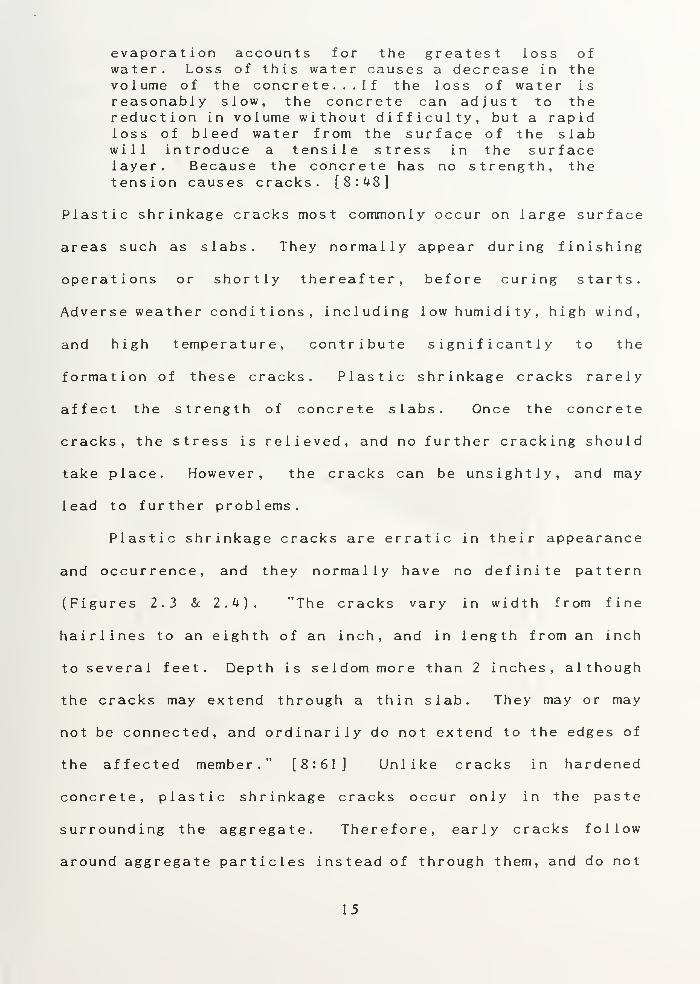
Plastic shrinkage cracks most commonly occur on large surface
areas such as slabs. They normally appear during finishing
operations or shortly thereafter, before curing starts.
Adverse weather conditions, including low humidity, high wind,
and high temperature, contribute significantly to the
formation of these cracks. Plastic shrinkage cracks rarely
affect the strength of concrete slabs. Once the concrete
cracks, the stress is relieved, and no further cracking should
take place. However, the cracks can be unsightly, and may
lead to further problems.
Plastic shrinkage cracks are erratic in their appearance
and occurrence, and they normally have no definite pattern
(Figures 2.3 & 2.k). "The cracks vary in width from fine
hairlines to an eighth of an inch, and in length from an inch
to several feet. Depth is seldom more than 2 inches, although
the cracks may extend through a thin slab. They may or may
not be connected, and ordinarily do not extend to the edges of
the affected member." [8:61] Unlike cracks in hardened
concrete, plastic shrinkage cracks occur only in the paste
surrounding the aggregate. Therefore, early cracks follow
around aggregate particles instead of through them, and do not
15


have the appearance of a clearly defined, clean break. The
crack is not a fracture in the hardened concrete, but a
separation of the plastic concrete material.
Figure 2.3 Typical plasticshrinkage cracking. (Ref 6)
V(.{
-igure 2.k Severe Plastic shrinkage cracksin a floor slab. (Reference 10)
16


The second category of early cracking occurs from
settlement or movement of the concrete in the formwork after
compaction and finishing is complete. There are several
causes of settlement cracks. Shi ft ing form cracks occur if
forms are not solidly built. The form does not have to
completely fail to cause a cracking problem. Any shifting,
slipping or bulging of forms that are not adequately built, or
braced, may cause cracking. If the form moves after initial
concrete placement, the fresh concrete will move with it, thus
creating a crack due to the concrete's low tensile strength
(Figure 2.5). These cracks have no particular pattern, but
are normally up to y inch deep, and wider at the surface.
"Sometimes this crack appears near the form, and at other
times further away." [3:72] Like shrinkage cracks, shifting
form cracks are unsightly and can lead to further
deter iorat ion
.
.0:
J.0
o
mm•0;
oa
JmiS
O'.a
o:^Q;mo 0:0:dp.pyf.
Figure 2.5 Shifting Form Crack(Reference 3)
17


Similar to shifting forms, a subgrade that yields or
settles will also cause cracks. These subgrade failures are
sometimes referred to as subgrade paper rupture cracks. Poor
compaction, irregular surfaces, expansive soils, and the
presence of mud or soft organic material can all result in a
yielding subgrade. Again, there is no pattern to the cracks.
Another type of cracking in plastic concrete occurs
because of obstructed settlement. Reinforcing steei cracks
occur when the concrete settles over reinforcing steel or
other embedded items. After initial placement and compaction,
the concrete will continue to consolidate. If this
consolidation is restrained by reinforcing steel, the concrete
gets "hung up" and a crack develops above the restraining
element. The crack may penetrate down to the reinforcement,
and voids often develop below the reinforcement (Figure 2.6).
This type of settlement crack normally increases with
increasing bar size, increasing slump, and decreasing cover.
Figure 2.6 Obstructed settlementcrack. (Reference k)
18
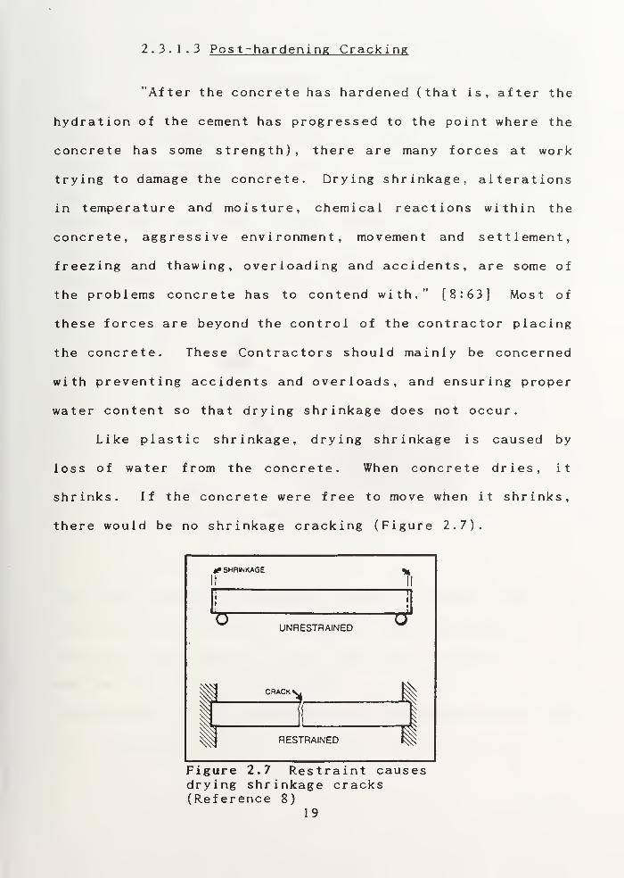
2.3.1.3 Post-hardening Cracking
"After the concrete has hardened (that is, after the
hydration of the cement has progressed to the point where the
concrete has some strength), there are many forces at work
trying to damage the concrete. Drying shrinkage, alterations
in temperature and moisture, chemical reactions within the
concrete, aggressive environment, movement and settlement,
freezing and thawing, overloading and accidents, are some of
the problems concrete has to contend with." [8:63] Most of
these forces are beyond the control of the contractor placing
the concrete. These Contractors should mainly be concerned
with preventing accidents and overloads, and ensuring proper
water content so that drying shrinkage does not occur.
Like plastic shrinkage, drying shrinkage is caused by
loss of water from the concrete. When concrete dries, it
shrinks. If the concrete were free to move when it shrinks,
there would be no shrinkage cracking (Figure 2.7).
rf SHRINKAGE
1
UNRESTRAINED
CRACK
]RESTRAINED
1
-a
Figure 2.7 Restraint causesdrying shrinkage cracks(Reference 8)
19


But all concrete is restrained in some way. Adjacent
structures or structural members, the subgrade under the slab,
reinforcement, and formwork all prevent the slab from moving
freely. Consequently, the concrete cracks. Drying shrinkage
cracks usually appear as "random, straight, hairline cracks
that extend to the perimeter of the slab... These cracks are
shallow and offer no serious problem beyond marring the
appearance of the concrete" (Figure 2.8). [3:71] However,
drying shrinkage will tend to widen cracks caused by other
factors, such as plastic shrinkage.
Figure 2.8 Typical dryingshrinkage cracks (Reference 3)
The higher the water content for a batch of concrete, the more
that concrete will shrink. Therefore, drying shrinkage can be
reduced by employing the lowest usable water content, and the
maximum practical aggregate amount in the mix. Shrinkage
cracking can also be controlled be using properly placed and
constructed control joints. These joints create a plane of
20


weakness so that the concrete will crack at the desired
location, rather than randomly.
2.3.2 Surface Defects
Regardless of design and specification adequacy,
achieving a uniform, blemish-free concrete surface is often
difficult. Both formed and unformed surfaces can exhibit
undesirable defects such as scaling, dusting, and pits and
voids, that mar the concrete's appearance. Some of these
defects are strictly related to formed surfaces, while others
occur only on unformed surfaces. Since the underside of
elevated slabs are formed, and often open to view, both types
of defects will be discussed.
2.3.2.1 Scaling
Scaling of concrete surfaces is defined as "local flaking
or peeling away of the near surface portion of concrete or
mortar" [^:8]. Generally, scaling starts as small patches,
which may merge and extend to larger areas. The effect ranges
from light scaling, in which only the surface mortar is lost,
to very severe scaling, in which the coarse aggregate is lost
with the mortar. Light scaling does not expose the aggregate
(Figure 2.9)
.
Scaling is generally attributed to freeze-thaw cycles
when moisture is present in the concrete, or to the
application of deicing salts on new concrete. However,
21


improper construction methods will also cause scaling. Any
finishing operation performed while there is still bleed water
on the surface will lead to a weak surface and possible
scaling. Insufficient or improper curing will also lead to a
weak surface, and scaling. Thin flakes of concrete may also
break away by adhering to the forms when they are removed.
-igure 2.9 Scaled concrete(Reference k)
2.3.2.2 Dusting
Like scaling, dusting is another effect of a weak or
soft concrete surface. Dusting surfaces are easily identified
by rubbing the hand over the surface— a soft surface will rub
off on the fingers. Dusting is especially noticeable on
concrete slabs because they will powder or chalk under any
traffic, and are readily scratched, even with a fingernail or
22


broom. Dusting can be caused by any finishing operation while
bleed water is still present on the surface, and by inadequate
curing. In addition, inadequate ventilation of close quarters
where carbon dioxide may be present (from gasoline engines or
generators) can cause a chemical reaction known as
carbonat ion. This reaction reduces the strength and hardness
of the concrete surface. [5:186]
2.3.2.3 Blisters
Blisters are defined as "hollow, low-profile bumps
on the concrete surface typically from the size of a dime up
to an inch, but occasionally even 2 or 3 inches in diameter"
(Figure 2.10). [5:197] The blisters can be difficult to see,
and may not be detected until they break open under traffic.
Figure 2.10 Concrete blisters(Reference 5)
Blisters can occur when the concrete surface is sealed by
trowling, and the underlying concrete is still plastic. By
23

closing the surface too earty, water and air are not permitted
to exit the concrete mass. The water and/or air then collect
under the surface "skin" to form a void (Figure 2.11).
DENSE TROWELED SURFACE
Figure 2. II Concrete blisterformation (Reference 5)
Concrete surfaces are often closed too early because they set
faster than the underlying concrete. Rapid setting of the
surface concrete can be brought about by: too sticky a mix;
excessive fines at the surface from overscreeding
,
over v i brat ion , and excessive or improper floating; and from
climatic conditions. [7:39]
2k

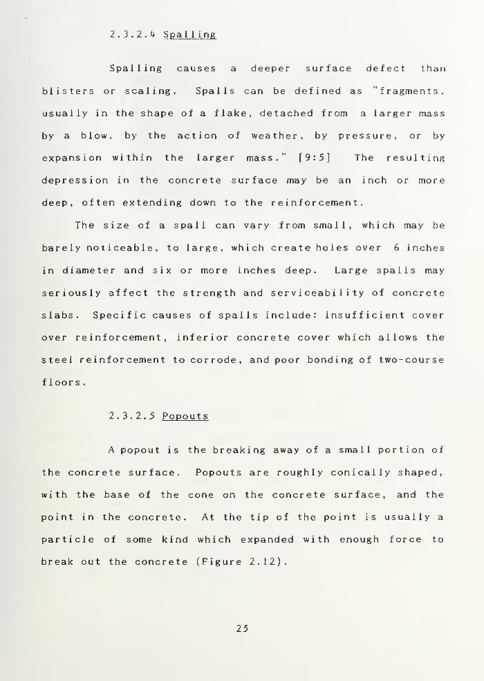
2.3.2.4 Spalling
Spalling causes a deeper surface defect than
blisters or scaling. Spalls can be defined as "fragments,
usually in the shape of a flake, detached from a larger mass
by a blow, by the action of weather, by pressure, or by
expansion within the larger mass." [9:5] The resulting
depression in the concrete surface may be an inch or more
deep, often extending down to the reinforcement.
The size of a spall can vary from small, which may be
barely noticeable, to large, which create holes over 6 inches
in diameter and six or more inches deep. Large spalls may
seriously affect the strength and serviceability of concrete
slabs. Specific causes of spalls include: insufficient cover
over reinforcement, inferior concrete cover which allows the
steel reinforcement to corrode, and poor bonding of two-course
floors
.
2.3.2.5 Popouts
A popout is the breaking away of a small portion of
the concrete surface. Popouts are roughly conicaily shaped,
with the base of the cone on the concrete surface, and the
point in the concrete. At the tip of the point is usually a
particle of some kind which expanded with enough force to
break out the concrete (Figure 2.12).
25


gqjmcjj jit—n .-
Figure 2.12 Typical popouts(Reference 8)
Popout holes typically range in size from % inches to 2 inches
in diameter. Popouts may be unsightly, but they normally do
not impact the integrity of the concrete. However, if
appearance or a smooth surface are particularly important, the
popouts will have to be repaired.
The most frequent cause of popouts is impurities in the
concrete mix. Soft, lightweight, porous materials can retain
moisture and expand when frozen. Other aggregates react with
the cement to cause popouts. Since the presence of impurities
in the mix is usually beyond the control of the constructor,
he should make every effort to ensure that the concrete
producer has taken steps to alleviate the problem. Also, the
need to follow good construction practices concerning the mix,
finishing, and curing cannot be overs tressed .
26


2.3.2.6 Honeycombing
Honeycombing is usualiy considered to be a formed
surface defect. As such, this problem is not normally
encountered in slab work, unless the slab is elevated, and the
underside is formed. Honeycombing occurs when the cement
mortar fails to fill all the spaces around the coarse
aggregate. It is easily recognized by voids in the surface
where the concrete appears as coarse aggregate coated with
mortar with no mortar between the coarse aggregate particles
(Figure 2.13).
;Vi- ,_.'. n-7 '\/- VV '"•''ft "-» -\i
ifcBha J l.
^Figure 2.13 Surface Honeycombing(Reference 3)
Beyond its unsightly appearance, honeycombing can severely
weaken an area of concrete. This problem can be especially
troublesome when the honeycomb is not obvious, but within the
concrete member (Figure 2.14).
27


•^SgS******^
Figure 2.14 Honeycombingwithin concrete (Reference 4)
Honeycombing is caused by lack of consolidation or compaction
of the concrete in the forms. When the concrete is first
placed in the forms, it contains entrapped air. Failure to
consolidate the concrete thoroughly through vibration, will
cause voids in the concrete. Honeycombing can also be caused
by loss of cement mortar through leaking forms, and by
segregation of the concrete from overly fluid mixes.
Segregation also occurs from improper handling, and excessive
coarse aggregate in the mix. [8:73]
2.3.3 Joint deficiencies
Joints are placed in concrete to allow movement, and
minimize cracking or cause the concrete to crack in a desired
location. However, failure to properly place and construct
the joints can result in unwanted problems, and can shorten
28


the life of the slab. In addition, even proper joints can
exhibit deterioration, wear and deformation, especially if
they are not maintained. Typical problems that occur at
joints include: corner failures, joint separation, joint
spalling, joint failure, and faulting or stepping. These
problems are self-explanatory, or have already been
characterized above, and no detailed description is required.
All of the joint deficiencies can be attributed to a few
common causes. Any slab is only as good as the base on which
it rests. Therefore, a weak base, or a base which is allowed
to weaken over time, will contribute to joint failure. Lack
of sealant material will allow water to reach and erode the
base, and allows the joint to fill with other foreign matter
which can expand and cause the joint to fail. Improper joint
materials or construction may inhibit the desired movement and
eventually result in cracks or faulting. Spalling may result
from poor timing in sawing control joints.
Spalling also results from hard-wheeled material handling
equipment crossing the joint, or from other impacts. Metal
keys left in place create a concrete "nose" that can break
off. As wheels continue to cross over the joint, the metal
key continues to strike the joint edge and cause further
damage (Figure 2.15). In addition, in those cases where a
joint is sealed with elastomeric material, the joint can spall
because the sealant only keeps out dirt and moisture, and does
nothing to protect the joint from impact (Figure 2.15).
29


PROBLEM:METAL KEY LEFT IN PLACE
ORIGINAL CONDI FION
'> S -
'• A ^\
/"- /
<Yy />
ii.
(J '
i) '
PROBLEM:ELASTOMERIC SEALANT
ORIGINAL CONDITION
Broken off edges-
Figure 2.15 Causes of joint edge spaliing(Reference 20)
30

CHAPTER I I I
GENERAL REPAIR PRINCIPLES
3 .
1
Over v i ew
In spite of precaution and quaiity control during the
mixing and placing of concrete, there are occasions when
damage or defects occur. Before proceeding with any repairs
of these problems, an evaluation should be made to determine
the location, extent, and cause of the problem, and the need
for repairs, regardless of the age of the concrete. The key
to successful, long-lasting repair of concrete problems is to
implement and follow a repair program which takes into account
these considerations. A solid repair program should include
the steps necessary to evaluate the problem, choose a repair
method and material, prepare the surface, and complete the
r epai r
.
3 .
2
Evaluating Concrete Problems
Whenever a question is raised regarding the significance
of concrete defects, an evaluation of the structure or member
should be performed first. A thorough review will give clues
as to the cause of the defect, and will help to decide what
action, if any, should be taken. "Selection of a repair
program must be based upon a full assessment of the concrete
31


condition and its interacti >n within the structural system and
facility type. Failure to follow the above guideline may
place the engineer at considerable risk by generating a
program poorly suited to the structures needs." [11:6]
To properly assess a structure's condition and determine
the best repair solution, the evaluating engineer should
perform the following steps:
1. Initial preparation - to include a review of the
drawings, construction records, and any other
background information.
2. Preliminary inspection - to visually inspect and
document the location, extent, and severity of any
obvious problems. During this work, sketches should be
made and photographs taken to document all problems
found
.
3. Detailed inspection - Non-destructive testing to
determine the presence of internal problems, and the
depth of cracks or other defects visible at the
surface
.
k. Further investigation - if necessary, cores can be
taken for further examination.
5. Diagnos is - identification of the problem and its
cause
.
The combination of these five steps is generally referred to
as the Condi t ion Survey. For older buildings, these surveys
may become quite detailed and complicated. However, for
32


buildings under construction, the survey can most times be
completed fairly easily, without the need for destructive
testing. In either case, it is important to stick to the
system developed for evaluating problems, so that unusual or
hidden causes are not overlooked.
The American Concrete Institute (ACI) publishes several
guides to assist engineers in evaluating concrete problems.
ACI 201.1R-68. Guide for Making a Condition Survey of Concrete
in Service, and ACI 201.3R-36, Guide for Making a Condition
Survey of Concrete Pavements (Appendix A) both provide
excellent systems for investigating concrete problems. ACI
309.2R-82, Identification andControl of Consolidation-related
Defects in Formed Concrete (Appendix B) provides guidance for
evaluating and preventing surface defects. In addition,
guidance on examining and sampling concrete in construction
may be found in ASTM C 823. The ACI guides also outline the
records which should be kept during construction to facilitate
repairs, if they are needed, at any time during the life of
the structure.
3 . 3 Choosing a Repair Method
Based on the diagnosis of the problem from the condition
survey, a repair procedure may be selected. Depending on the
type and extent of damage, several methods may be available
for use. Cracking, for example, can be repaired by stitching,
injection, routing and sealing, grouting, drilling and
33


plugging, drypacking , overlays, and other methods . The repair
method decision is important, as choosing the wrong method may
result in a worthless repair, and much unneeded effort.
Beyond the extent and cause of the problem itself, those
contemplating concrete slab repair should also consider the
ability of the surrounding concrete to support the repair, the
intended function of the slab, the objectives of the repair,
the difficulty involved, the time allowed for the repair work,
the expertise required, and the cost. Unfortunately, cost is
often the driving factor, as limited funds usually allow only
less expensive or temporary repairs. These repairs frequently
address only the effect, and not the cause.
The key factor involved in method selection should be the
objectives of the repair. "...Procedures can be selected to
accomplish one or more of the following objectives:
1. Restore or increase strength;
2. Restore or increase stiffness;
3. Improve functional performance;
U . Provide water
t
ightness ;
5. Improve appearance of the concrete surface;
6. Improve durability; and/or
7. Prevent access of corrosive materials to
reinforcement." [6:11]
With a definite objective in mind, a specific repair method
can be chosen. Aside from the profusion of proprietary repair
methods and materials, the range of repair methods is fairly
3k


limited. The basic repair methods are: concrete replacement,
patching, overlays, sealing, shotcreting and injection.
3
.
k Choosing a Repair Material
The nearly unlimited choice of specialized repair
products makes choosing the right material for the job
difficult, but important. "The proper selection of materials
for a repair program is normally more involved and important
than it is for new construction." [11:6] Repair products on
the market today represent a wide range of properties,
quality, difficulty of use, and cost, and it is not always
necessary to choose the most expensive product.
The useful life of any concrete repair work will depend
on the skill of the craftsmen and the quality of their work,
the conditions to which the repair is exposed, and the
location of the repair in the structure. "The choice of the
repair material to be used will depend not only on the
particular nature of the problem but also on the function of
the structure, the availability of equipment and skilled
manpower, the relative importance of appearance, and of course
the funds available for the repair." [3:111] When selecting
a repair material, a contractor should consider the type of
material required, and the properties of that material.
35


3.^.1 Material Types
For simplicity, concrete repair materials may be
classified into two groups: cementitious and polymers. The
cementitious types are those sand and cement mixtures which
only require the addition of potable water. Polymers are
those materials which require the addition of one or more
components (typically called setting agents) other than water.
Both types of materials have their own advantages and
disadvantages. [1:152]
Cementitious materials used in repair will most nearly
resemble the in-place concrete material in composition and
physical properties. These materials can be either
proportioned and mixed on site, or purchased as prepackaged
products. Cementitious materials have been employed for many
years, and require no special skills or expertise to be
effectively used. They are much more "user- f r i endl y " than the
polymer type, and most contractors have considerable
experience with them. With the addition of admixtures such as
polymers, cementitious materials can be created which have a
wide array of chemical and physical properties.
Polymers are complex substances that require the mixing
of two or more chemical components to produce a material which
hardens quickly, adheres well, and gains strength rapidly.
"These materials are often referred to as 'resins', and the
principle resins used in the construction industry are
epoxide, polyurethane,polyester, acrylic, polyvinyl acetate,
36


and styrene-butadiene." [10:251 Polymers require some skill
and experience to be used effectively. Because they harden
quickly, they can be difficult to work with. Polymers also
display varying levels of toxicity and f lammabi 1 i ty , and must
be used with caution.
3.^.2 Material Properties
When evaluating alternative repair materials, several
material properties should be considered. Bond s trength is
probably the single most important property of the repair
material. Most repairs that fail do so because of the lack of
adequate bond between the repair material and the substrate.
This failure often results in the entire repair "popping out",
or flaking off. In fact, the increased development and usage
of polymers over the years has been primarily due to their
superior bonding capability.
It is essential to obtain the best possible bond atthe interface between existing concrete and mortaror concrete used for repair, and prior to theintroduction of polymer bonding aids, it was thepractice either to use nothing and rely on thepreparation of the surface of the base concrete, orto use a cement slurry. Both of these techniquesgave excellent results in the laboratory, but inthe field, the results were often disappointing...
It must be appreciated that the bond at theinterface between the concrete and the repairmaterial is likely to be subjected to considerablestress arising from changes in moisture content,freeze-thaw, a wide temperature range, as well asthe force of gravity, and sometimes vibration.[ 10:20]
37


Another essential property ^f a repair material is its ability
to resist thermal movement. Any length change through
shrinkage or expansion is likely to create cracking and/or
debonding
.
In most cases, whether using cementitious or polymer
materials, the strength of the repair material will be equal
to or greater than the concrete to be repaired, and there is
no real advantage in specifying a repair product based solely
on its strength. However, in those instances where the repair
material is expected to contribute to the strength of a
structure, the required strength should be specified.
Other properties of the repair material which should also
be considered are its:
1. modulus of elasticity;
2. creep characteristics;
3. rate of strength gain;
k . durability;
5. consistency, workability, and speed of
appl i cat ion
;
6. permeability; and
7. chemical resistance.
Finally, although one, or several of these properties may
represent the vital factor in deciding on a particular repair
material, the all-around performance of the material for the
situation at hand must also be examined. This examination
should include the materials' compatibility with other
38

materials used in the repair. In general, polymers should be
used where a thin repair section is required. For larger
repairs, cementitious materials are preferred because of their
lower cost, greater compatibility with the existing concrete,
and better workability. In either case, it is always
advisable to contact the material manufacturer to discuss
specific properties, uses, and installation requirements.
3 . 5 Preparations for Repair
After the condition survey has been completed, and the
repair method and material chosen, the area to be repaired
should be checked again to ensure all damaged or defective
areas are marked for repair. "No matter how carefully the
investigation has been carried out it will not have revealed
all the areas of defective concrete; in fact it was not
intended to do this, but to establish the cause and general
extent of the deterioration and provide the information needed
to prepare a specification for the remedial work." [10:91]
When all areas requiring repair have been marked, the surface
must be prepared for execution of the repairs.
The condition of the surface to accept the repairs is
just as important as the selection of the repair material. A
properly prepared surface is essential to provide good
adhesion and support for the repair material, and to ensure a
long lasting repair. "Regardless of the repair product
selected, the success of the project will depend not only on
39


the material used, but also on the preparation of the area to
be repaired." [3:102] A poorly prepared surface will become
the weak link in any repair.
Surface preparation requires a systematic approach which
can evaluate the existing condition and prepare the surface
for the specific repair material to be used. Merely providing
a "clean and dry" surface is insufficient, as these terms are
open to interpretation, and the surface must also be strong
enough to support the repair, and must not be smooth. In
general, the recommended procedures for proper surface
preparation include:
1. Sawcutting around the area to be repaired. Minimumsawcut depth is 1 inch, but 2 inches is preferred.
2. Removal of all loose material, and any weak,defective concrete. This work can be accomplished byhand chipping, pneumatic tools or high velocity waterjets. Care should be taken to ensure that the use ofpneumatic tools does not create additional cracks inthe sur face
.
3. Removal of all detrimental substances including oil,grease, dirt and curing agents. Water or sand blastingwork well, but chemical cleaners such as acids and/ordegreasers can be used. However, all acids anddegreasers must also be thoroughly removed. Grindingshould be avoided, as it leaves the area too smooth.
U. Cleaning to bright metal any reinforcement which isuncovered, especially if using polymers in the repair.This step is normally accomplished by sandblasting.
5. Roughening the surface to improve adhesion.Mechanical means such as chipping or bush-hammering maybe used. Acids which remove the cement paste down tothe fine aggregate are also effective.
6. Final cleaning of the repair area with compressedair immediately prior to repairs, to ensure that thesurface has not become soiled, and all fine dust is
removed
.


CHAPTER IVMATERIALS AND METHODS OF REPAIR
k . 1 Over v i ew
Good repairs can always be made by following the
fundamentals of thorough preparation, using quality materials,
and proper application methods. General information on
selecting repair materials and methods, along with guidelines
for surface preparation were provided in Chapter III. This
chapter will describe in detail the properties and uses of the
major repair materials available on the market today. It will
also discuss the methods used to repair concrete slab defects
and damage.
k . 2 Mater ials
There are many materials available today to repair
concrete. The most commonly used are cement-based concretes,
and mortars, but resin-based materials such as epoxies and
polymer concretes have also seen widespread use. Other
proprietary materials are also constantly being developed and
placed on the market. Many of these proprietary materials are
good, but some are suspect and their effectiveness remains to
be proven. New materials add an extra variable to the repair,
but reliable manufacturers should freely give information on


the use and composition of their products. Users should also
check independent laboratory test results and the history of
use of the product under similar circumstances. Criteria for
selecting a repair material is provided in section 3.k.
4.2.1 Cementitious Materials
Cementitious repair materials are made with the same
cement and aggregates used in concrete construction, and they
achieve physical properties very similar to concrete.
"Requirements for repair concrete are generally the same as
for original construction except for restrictions to limit
traffic obstruction time and to minimizing differential volume
changes." [12:1 ^5 ] Cementitious materials have the advantages
of being well known, readily available, and reasonably low in
cost. The main disadvantage of cementitious materials (used
alone) is their lack of adequate bond strength.
The design of a cementitious mix can be changed to
accommodate almost any repair situation. The considerations
which dictate the mix design are the depth of the repair, and
the workability of the mix. "The maximum size of the coarse
aggregate should be about half the thickness of the
resurfacing. The mix should be workable--at a water-cement
ratio of not more than 0.45." [3:301] In addition, where
exposure to freezing and thawing is anticipated, the concrete
should be air entrained.
kl


Special cements are often used to modify the mix as
required. High alumina cement and rapid hardening cements can
be used to adjust the setting time and rate of strength gain.
Sulphate-resisting and other chemically resistant cements can
be used where chemical impregnability is required. Even
colored cements can be specified where the appearance of the
repair is important. In addition, admixtures can be used in
the mix to improve its bonding capability, strength
characteristics, and chemical resistance. The most common
materials of this type are latex modified concrete, and
polymer concrete.
Cementitious materials can also be used in conjunction
with a separate bonding agent to improve the bonding between
the newly placed cement-based material and the existing
concrete. In fact, for shallow depth patches and thin
overlays, a bonding agent is recommended. Bonding agents may
consist of portland cement grout, latex modified cement grout,
or an epoxy system.
^.2.2 Pol ymer
s
While cementitious materials are the older, and more
widely used repair materials, new products are being
increasingly used for repair and protection of buildings
constructed from traditional materials. The major area of new
material development is that of synthetic polymers such as
epoxies, pol yur ethanes ,polyester, latexes, and polyvinyl
k3

acetate. These chemical compounds have not replaced
traditional repair materials, but their types and uses have
become widespread, especially where special benefits or
specific material properties are required. [13:392] "While
the range of use of these materials is very wide, it is
convenient and practical to divide it into two main
categories; namely, coatings in which the formulated compound
is used on its own, and mortars and concretes in which the
resin is mixed with aggregate and sometimes cement." [10:25]
4.2.2. 1 Res ins /Pol ymers/Adhes i ves
The term resins refers to materials which are
chemical compounds, derived mostly from the petrochemical
industry (the term is often used synonymously with polymers).
There are many types and formulations of resins. As stated,
these can be used alone, or combined with mortar mixes. For
the purpose of this report, the term adhes ive will be employed
for those polymers which are used alone. The term polymer
concrete will be used when the polymer is combined with a
mortar mix.
Adhesives are normally made of two components, consisting
of the basic resin, and an accelerator (sometimes called a
hardener). The two components must be mixed immediately prior
to their use. Some of the more important considerations
relating to mixing and using resins are:
kk


1. Pot life. This is the amount of time which caneiapse between mixing the resin components, andapplying the resin where needed. This time can bevaried by the formulator, but it is normally fairlyshort. Therefore, only the amount of material whichcan be applied within the pot life should be mixed atone time.
2. Hardening. This is the time required for physicalsetting of the plastic resin after application. It canalso be varied by the formulator of the resin.
3. Curing. This is the time when the molecular linkageof the resin takes place, and the resin gains strengthand durability. The average curing time, depending onambient temperature, is 7 days. This time can also bevaried. [10:27]
The oldest and most widely used adhesives are the
epoxies. There are literally hundreds of compounds, now on
the market, known as epoxy. To help avoid confusion, ASTM
Standard C 881 provides requirements for three types, three
grades, and three classes of epoxy for use with concrete.
Type I epoxies are those designed for bonding hardened
concrete to hardened concrete, as in the case of crack repair.
Type II epoxies are for bonding freshly mixed concrete to
hardened concrete, as in spall repair and patching. Type III
epoxies are for bonding skid-resistant materials to hardened
concrete. Epoxy grades are based on consistency and viscosity,
while the classes are based on ranges of temperatures for
which the epoxies are suitable for use (table k.l).
k5


Table 4.1 Grades and classe s of Type I epoxies1^————1 I i—
—
OBH^^m ^———^^——————Grade 1 Maximum viscosity 20 poises
Grade 2 Minimum viscosity 20 poises
Maximum viscosity 100 poises
Grade 3 Consistency, maximum £ inch
Class A For use below ^0 degrees F
Class B For use between kO & 60 degrees F
Class C For use above 60 degrees F
=( Reference 1 k
)
Besides viscosity and temperature range, epoxies can be
custom formulated to obtain a wide range of properties to meet
specific, specialized needs, or for general use. These
properties include the ability to cure at very low or high
temperatures, the ability to cure under moist conditions, low
to high modulus, and chemical resistance. Epoxy resins have
seen increased usage in the concrete repair area because they
have a much greater bond strength and quicker strength
development than cementitious products, and their curing
shrinkage is extremely small.
Polyurethanes are also resins that are commonly used on
their own for concrete repairs and protection. These
adhesives can be obtained as elastomers (any elastic,
rubberlike substance), rigid materials, and as flexible
coatings. Like epoxies, polyurethanes are very durable, and
can be formulated with varying properties to meet specific
kS


requirements. One important characteristic of po i yure thanes
is that they will cure in temperatures below freezing, while
epoxies cannot be relied on to cure below 40° F.
4.2.2.2 Polymer Concrete
A relatively new, but widely accepted repair
material is resin mortar. These materials, commonly referred
to as polymer concrete, essentially consist of mineral
aggregates bonded by resins. "...Polymer concrete is concrete
in which the cement is replaced either entirely or principally
by an organic polymer such as epoxide or polyester resin, or
normal concrete which contains polymer as an additive."
[10:29] Concretes and mortars containing these mater ial s have
"several advantages over their cement based counterparts that
include rapid strength development, superior compressive and
tensile strengths and good adhesion to both steel and concrete
substrates." [13:478]
Many materials are used to make polymer concrete
including epoxies, polyesters, methyl methacrylate (MMA) , and
synthetic latexes such as acrylics, polyvinyl acetates (PVA)
and s tyrene-bu tadi ene . The most successful polymer concretes
have been those that use epoxy formulations or MMA. However,
latex mod i f i ed concrete (LMC) has enjoyed increased popularity
in the last several years.
Epoxy concrete generally consists of an epoxy system with
aggregate as recommended by the epoxy formulator. The most
47

commonly used aggregate is silica sand. with mortars
consisting of k to 7 parts sand to 1 part resin, and increased
ratios for the larger aggregates used in concrete. The
maximum aggregate size should be no more than !^ the thickness
of the repair. Accurate batching and proper mixing of ail
these components are essential, and should be performed as
recommended by the manufacturer. [12:151] Epoxy concrete is
normally used for patching and overlays. It has many
advantages over normal concrete including greater durability
and resistance to wear, a lower absorption rate, greater
flexural and tensile strength, and resistance to impact loads.
Methyl methacrylate (MMA) polymer concrete has been in
use for over 20 years. This polymer concrete consists of
aggregate and a monomer (liquid) which is polymerized
(solidified) in place. These components of MMA can be
formulated by the user, or a pre-packaged system can be used.
The pre-packaged systems contains the fine aggregate coated
with polymers, the monomer component (MMA), initiators, and
pigments. "Initiators are materials required to start
polymerization and promoters are chemicals to accelerate
polymerization." [12:152] When MMA systems are formulated by
the user, the initiator and promoter must be added.
There are several different MMA systems, each suited for
a particular application. MMA polymer concrete has about the
same modulus of elasticity and coefficient of thermal
expansion as normal concrete, making it an ideal repair


material because the stresses it exhibits are similar to
normal concrete. Additionally, "MMA has many advantages over
conventional concrete, including among others, rapid setting,
ease of use, usability in hot and cold temperatures and water
and salt resistance." [13:398] MMA can be effectively
utilized for thin and deep spall repairs, full depth repairs,
and both thin (£"-1") and thick (l£"-2") overlays.
Latex modified concrete ( LMC ) consists of a portland
cement mortar or concrete with the addition of a synthetic
latex modifier such as s tyr ene-butadi ene . Synthetic latexes
are plastic particles (polymers) suspended in water. These
fluids are manufactured with varying percentages of solids,
and are added to standard concrete to produce a mix with
superior durability and bonding characteristics. Selection of
the latex modifier should be based on anticipated service
conditions, as each particular modifier will influence the
strength and durability of the concrete differently. [12:149]
In concrete repair work, LMC is most often used for
patching and overlays, especially on bridges and parking
garages. Patches made with LMC may be made in thicknesses
greater than j inch, but are not recommended for thinner
repair sections. A minimum thickness of 1£ inches is
preferred for overlays.
With the many advantages polymer concretes have over
cementitious repair products, they would seem to be an ideal
repair material. Yet, polymers also have their disadvantages.
k9

Their short pot life and rapid hardening may produce placement
and cleanup difficulties. As with most chemicals, polymers
are volatile, flammable and can be toxic. In fact, MMA
initiators and promoters can explode if mixed directly
together. As with normal concrete, polymers require special
attention during curing to ensure the material reaches its
full potential in strength, bonding and durability. Lastly,
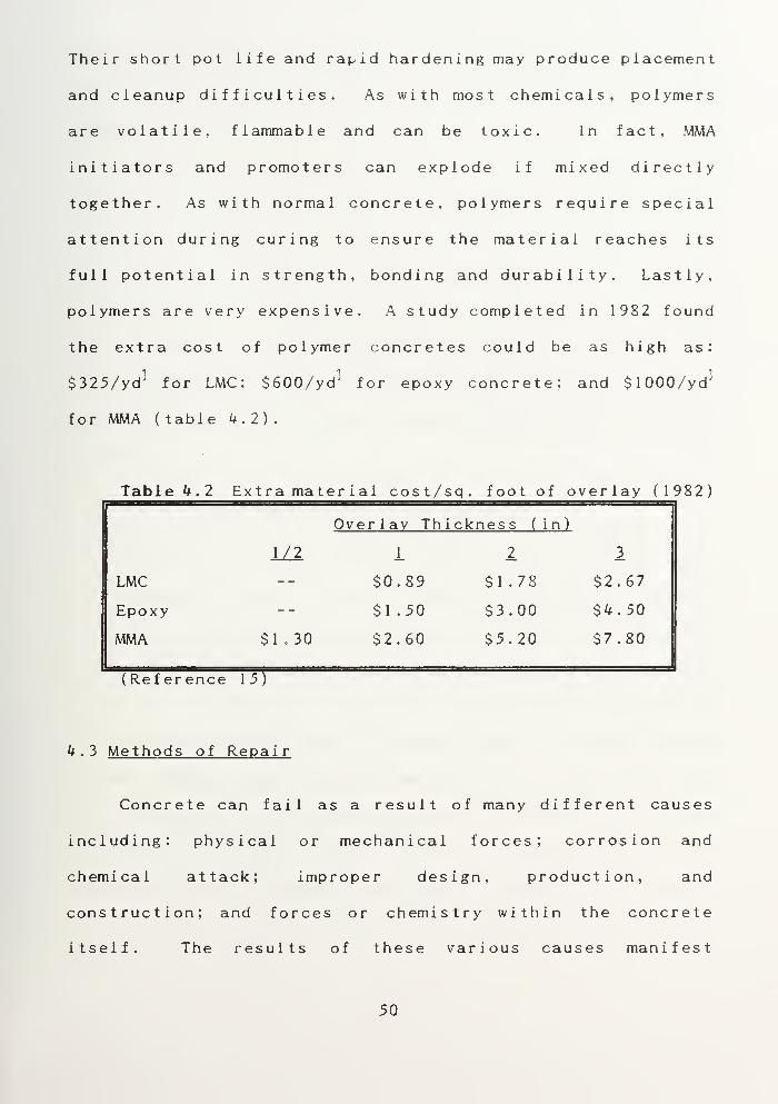
polymers are very expensive. A study completed in 1982 found
the extra cost of polymer concretes could be as high as:
$325/yd' for LMC; $600/yd 3 for epoxy concrete; and $1000/yd ]
for MMA ( table k.2) .
Table k.2 Extra mater ial cost/sq. foot of overlay (1982)i i . i 1 1 i i .
i I i i —i
Overlay Thickness (in)
1/2 12 3
LMC -- $0.89 $1.78 $2.67
Epoxy -- $1.50 $3.00 $k . 50
MMA $1.30 $2.60 $5.20 $7.80
(Ref er ence TTT
k . 3 Methods of Repair
Concrete can fail as a result of many different causes
including: physical or mechanical forces; corrosion and
chemical attack; improper design, production, and
construction; and forces or chemistry within the concrete
itself. The results of these various causes manifest
50


themselves in many different forms. Because of these two
facts, every concrete problem has unique characteristics, and
consequences of repair.
To ensure an effective repair, each concrete problem
should be evaluated according to its own set of circumstances,
and a specific repair method and material determined. In
general, the contractor performing concrete slab repair must
be familiar with the methods required for patching and small
scale repairs, concrete replacement, repairs to joints, and
repairs to cracks. Prior to commencing any of these repairs,
the surface should be properly prepared as outlined in chapter
3 ( section 3.5).
^.3.1 Patching and Small Scale Repairs
Patching is the preferred method for repairing small
isolated spall areas, and other surface defects such as holes,
blisters, shallow honeycombing, and popouts. The size of the
spall and the condition of the surface control repair material
selection. Small spalls and voids, where bond and shrinkage
are not as critical, can be filled with a straight cement
mortar. Larger spalls can be repaired with normal concrete,
dry pack mortar, preplaced aggregate concrete, or polymer
concrete. If normal concrete is used, a bonding agent should
be applied first. Shotcrete can also be effective for making
shallow repairs, especially on the underside of overhead
s labs
.
51


"The dry pack method consists of ramming a very stiff mix
into place in thin layers." [17:32] Because concrete shrinks
as it dries, dry pack mixes are prepared with just enough
moisture to be workable. Slump for these mixes should not
exceed 1 inch, but no slump is preferable. "Practically no
shr inkage wi 1 1 occur with this mix, and it develops a strength
equalling or exceeding that of the parent concrete." [17:32]
This method does not require any special equipment. The dry
pack mortar should be forced into the hole, then compacted
with hand tamps to ensure it is packed tightly. The surface
is then levelled off, and cured by fog spraying or covering
with wet cloth or burlap.
The preplaced aggregate method utilizes normal aggregate
with a polymer binder. In this method, the aggregate is
premixed, then placed into the hole and screeded to the
required level. The components of the polymer (a monomer and
an initiator) are then thoroughly mixed together and poured
over the aggregate. The patch should then be consolidated by
tamping or vibration, taking care to avoid segregating the
aggregate from the liquid polymer. After the liquid polymer
has filled the patch area and ponded on the surface, screeding
is performed to level the surface. Sand should be added to
avoid a slick surface. Polymers are volatile, so the surface
should be covered to avoid evaporation losses.
Any of the polymer concretes reviewed in section 4.2.2.2
can be used for patching. Surface preparation is the same as
52


for normal concretes, but curing is much faster so the slab
may be returned to service earlier. Because of their improved
bonding, reduced shrinkage and permeability, and increased
strength and durability, Polymer concretes are recommended
over normal concrete.
Small scale repairs include the removal of small surface
protrusions, and filling of air holes. Protrusions such as
surface fins, bumps, and blisters can be removed by grinding,
mechanical impact, or rubbing with a carborundum stone. Air
holes can be filled with a mortar consisting of 1 part sand,
and ly parts sand, when the concrete is more than a day old.
[ 16:293]
4.3.2 Concrete Replacement
The concrete replacement method consists of replacing all
defective concrete with new concrete which is similar to the
old in maximum aggregate size and water-cement ratio. The new
concrete becomes integral with the base concrete. A
considerable amount of concrete removal is required for this
type of repair. Faulty concrete should be removed until sound
concrete is reached, but the complete removal of concrete
should always be a last resort. There are occasions when
complete removal is required, such as a badly damaged slab,
but most concrete slabs can be repaired without replacing the
ent ire s lab
.
53


"Concrete replacement xS the desired method if there is
honeycomb in new construction or deterioration of old concrete
which goes entirely through the wall or beyond the
reinforcement, or if the quantity is large." [17:32] If
honeycomb is found in new work, the replacement should be made
immediately after stripping forms. Forming is often required
on large scale repairs, and it is sometimes necessary to pump
the concrete into the form.
^.3.3 Repairs to Cracks
There are many methods available to repair cracks in
concrete slabs. Epoxy injection, flexible sealing, drilling
and plugging, and grouting are only a few of the methods which
are being used today. Selecting the right method for the
situation at hand is important, but equally important is the
evaluation of the conditions which have caused the concrete to
crack, and the abatement of those conditions. "The proper
repair of cracks depends on knowing the causes and selecting
the repair procedure that take these causes into account;
otherwise, the repair may only be temporary." [6:1]
Another factor pertaining to crack repair is knowing when
to repair the crack, when to replace the concrete, and when to
leave the crack alone. "Only cracking that may potentially
endanger the structural adequacy of the member should be
considered for repair. Many cracks do not require repair,
some cracks cannot be repaired." [12:1^2] An exception to
5k


this "rule" is the repair of cracks for appearance or
serviceability reasons. Crazing, for example, has no
corrective treatment, nor is one required unless the owner
absolutely cannot live with its appearance. In that case the
concrete would have to be replaced or resurfaced.
In response to the uncertainties of determining when
cracks should be repaired, the AC I established tolerable
limits for crack widths in reinforced concrete. The tolerable
limit depends on the prevalent exposure condition (Table 4.3).
When crack widths exceed the tolerable width, repairs should
be implemented.
Table 4.3 Tolerable crack widths
Tol erabl
e
Exposure Condition crack width( inches
)
Dry air or protective membrane 0.016Humidity, moist air, soil 0.012Deicing chemicals 0.007Seawater and spray: wetting anddrying 0.006Water retaining structures* 0.004
*Excluding pressure pipes
For comparison, cracks become visible with the unaided eye at
about 0.004 inches. At about 0.02 inches the separation
between the two edges of a crack may be just visible. While
these size cracks can be estimated by eye, it is advisable to
use a crack gauge, or an optical instrument to determine a
precise crack width.
55

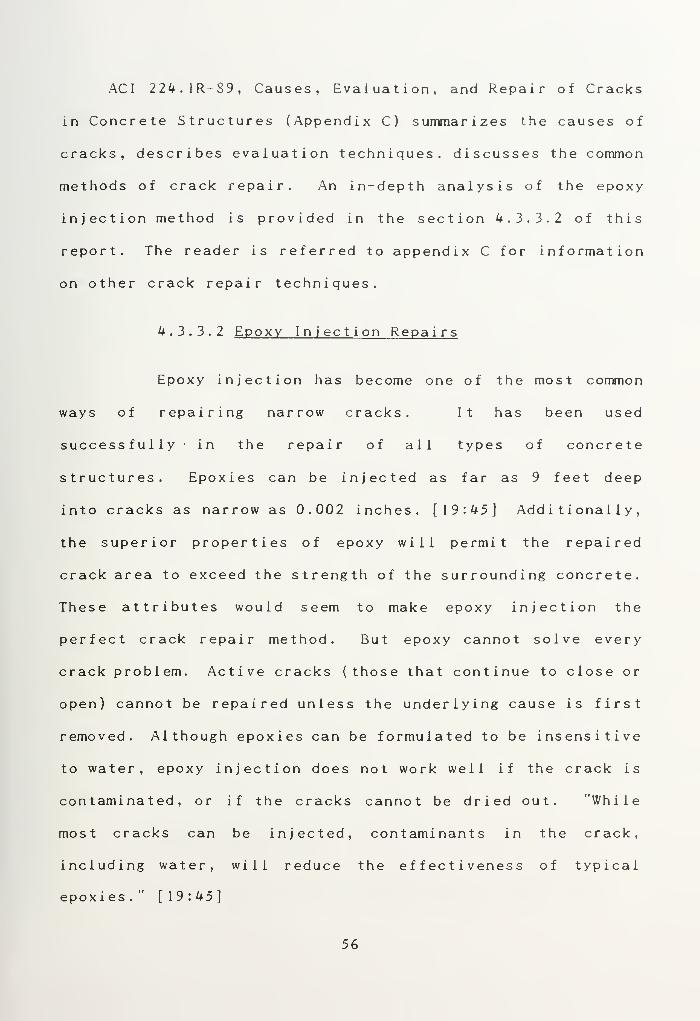
ACI 224.1R-89, Causes, Evaluation, and Repair of Cracks
in Concrete Structures (Appendix C) summarizes the causes of
cracks, describes evaluation techniques, discusses the common
methods of crack repair. An in-depth analysis of the epoxy
injection method is provided in the section 4.3.3.2 of this
report. The reader is referred to appendix C for information
on other crack repair techniques.
4.3.3.2 Epoxy Injection Repairs
Epoxy injection has become one of the most common
ways of repairing narrow cracks. It has been used
successfully in the repair of all types of concrete
structures. Epoxies can be injected as far as 9 feet deep
into cracks as narrow as 0.002 inches. [19:45] Additionally,
the superior properties of epoxy will permit the repaired
crack area to exceed the strength of the surrounding concrete.
These attributes would seem to make epoxy injection the
perfect crack repair method. But epoxy cannot solve every
crack problem. Active cracks (those that continue to close or
open) cannot be repaired unless the underlying cause is first
removed. Although epoxies can be formulated to be insensitive
to water, epoxy injection does not work well if the crack is
contaminated, or if the cracks cannot be dried out. "While
most cracks can be injected, contaminants in the crack,
including water, will reduce the effectiveness of typical
epoxies .
" [19:45]
56


When choosing an epoxy for crack repair, a contractor
should consider the epoxy's type, viscosity, moisture
sensitivity, pot life, and minimum curing temperature. Type
I epoxies (see section 4.2.2.1) should be used for all crack
repair. The viscosity requirement will depend on the type of
crack considered for repair. Narrow crack repair requires a
low- v i scos i ty epoxy which can penetrate deeply with ease.
Wide cracks may allow 1 ow- vi scos i ty epoxies to seep out
through a porous subgrade, or may create too large a volume of
epoxy, which can produce enough heat to cause the epoxy to
boil and froth. Wide cracks require a higher viscosity epoxy,
or a flowable epoxy mortar.
The procedures for epoxy injection are not complicated,
but they do require special equipment and a high degree of
skill to obtain satisfactory results. The basic procedure is
to inject the epoxy into holes drilled at intervals along the
crack. The epoxy may be applied through gravity, hand
operated pressure guns, low-pressure spring-actuated pumps, or
high-pressure injection equipment. Regardless of the
equipment, what is required with all crack injection is
uniform penetration and complete filling of the crack.
Specifically, the injection procedure requires these
s teps :
1. Clean out the crack. Contamination can be removedwith high-pressure water or air (if water is used,allow for drying time). At least a 1 inch strip oneach side of the crack should also be cleaned of allcontamination to ensure adequate bond of the surface
57


sealer. Avoid getting any dust in the crack ifgrinding equipment is used to clean the edges.
2. Seal the sur face
.
The "cap" over the crack actslike a form to contain the epoxy, and is not anintegral part of the repair. Selection of the capmaterial depends on the injection system. Low pressuresystems can be sealed with wax, while high pressuresrequire an epoxy adhesive. The material should alsohave a fast cure time so that sealing and injection canbe accomplished on the same day. Avoid creating anyskips or thin spots in the cap where epoxy materialcould later leak out.
3. I nstall the injection ports. Low-pressure systemsmay simply use an interruption in the seal. Higherpressures require an injection port bonded to thesurface over the crack, or fittings inserted intodrilled holes and bond with epoxy adhesive. Properspacing of the ports is important. In general, thesmaller the width of the crack, the closer theinjection ports should be spaced. "As a rule of thumb,the entry ports should be spaced at a distance equal tothe desired penetration of the epoxy but not exceedingthe thickness of the concrete or 12 inches, whicheveris less
.
" [19:49]
U . Mix the epoxy. It is important to batch and mix theepoxy properly, as improper batching will affect theepoxy's final properties. Only that amount of epoxythat can be used prior to the onset of the materialgelling should be mixed. "When the adhesive begins togel, its flow characteristics begin to change, andpressure injection becomes more difficult." [6:13]
5. Inject the epoxy. For horizontal cracking, there isno fixed order of injection. The key to successfulinjection is selecting the right injection pressure.Excessive pressure can cause further damage, too lowpressure and the crack will not be filled completely.When the pressure can be maintained, the crack is full.If the pressure cannot be maintained, the epoxy isstill flowing, or there is a leak in the cap.Sometimes, epoxy may also drain into the ground. Tocorrect this problem, the crack must be reinjecteduntil it remains full. This can be a costlyrequirement. However, the problem is not as severe innarrow cracks, and for wider cracks, the base of thecrack can be injected with a silicon sealer, or anepoxy grout can be used.
58


6. Remove the cap
.
This can be expensive. If
appearance is not a problem, leave the cap on place.
7. Evaluate the repair. For normal repairs, visualmonitoring of the crack area should suffice. In morecritical repairs, ultrasonic equipment can be usedduring the injection, or random cores can be takenafter hardening, to verify crack filling.Permeability and hardness tests can also be performedon the epoxy.
Epoxy injection can be a highly effective repair method. With
on-site support from an epoxy supplier, most routine repairs
should be satisfactory. But the process can be quite
technical, and the more sophisticated repairs should be left
to the specialist. "Epoxy injection can be an easy and
effective way to repair cracks, but if done wrong the bad
repair may be irreparable. There's simply no easy way to
remove epoxy from cracks." [19:^9]
k.3.k Repairs to Joints
Over the life of a concrete slab, one of the most
troublesome repair problems is that of damaged, deteriorated,
or defective joints. Think of driving over any concrete
highway. The constant ka-thunk of the tires running over
problem joints emphasizes this point. Although joints are
subject to many problems over their service life, the main
difficulty the construction contractor will face is joint
spal 1 ing
.
59


When performing joint repairs, the contractor shouid keep
in mind the foiiowing four principles [20:54S]:
1 . Re-establish a smooth surface ; A smooth surface at the
joint will help to ensure that future traffic does not
cause impacts to the joint area and additional spalling.
2. Don't weld slab units together ; Use of a rigid
adhesive in joint repair will "lock" the two slabs
together. If the concrete is shrinking, "gluing concrete
together at the joints can cause a chain reaction of
shrinkage related stress. Either the other joints will
open wider or cracks will occur between the joints."
[20:551 ]
3. Keep repairs as narrow as possible ; Wider repairs are
subject to greater exposure and possible failure.
k . Don't featheredge repairs ; Although many manufacturers
say their epoxies can be featheredged to zero, it is much
better practice to notch the repair with a saw cut at
1 eas t 1 i nch deep
.
Implementing these principles will ensure a long-lasting joint
repair. Specific repair procedures for a spalied joint
normally include cutting away the spalied area on both sides
of the crack, removing all material inside the sawed-out area,
and filling the area with repair material. In most cases, a
semi-rigid epoxy mortar is best for repairs up to ly inches
wide. For wider repairs, a higher strength epoxy can be used,
or a plastic strip can be used to prevent shrinkage stress.
60


CHAPTER VCONCLUSION AND RECOMMENDATIONS
5 . 1 Cone 1 us i on
When defects, damage or deterioration are encountered in
a concrete structure, repair of the problem areas is usually
a viable option. Concrete structures are rarely beyond
repair. There are numerous repair methods and materials
available to fix almost any problem. When selecting a repair
method and material, the repair contractor should consider the
objectives of the repair, the cost, the function of the
building, and the properties of the repair product. Cost
cannot, and should not, be the only consideration when
choosing a repair material, but often is the deciding factor
when determining i_f a repair is made.
Due to their many uses and exposure conditions, concrete
slabs present unique problems for construction and repair.
When these problems are anticipated and properly considered
prior to the construction, the slab should provide a long
service life without the need for repairs. However, if
improper or inadequate construction methods are used the slab
will inevitably need to be repaired.
Poor construction practices are the principal cause of
problems with concrete slabs. Often, the need for repair
61


arises before the contractor has even left the jobsite.
Over t rowl i ng or over vi brat i on can bring excess fines to the
top of the slab and create a weak concrete surface which will
easily scale, spall, and dust. Any finishing operation
performed while there is still bleed water on the surface will
also cause scaling, dusting, and crazing. Inadequate subgrade
preparation, insufficient formwork construction, and improper
curing will ail cause concrete slabs to crack. Failure to
properly place and construct joints in the slab will also Lead
to unwanted cracking.
The problems caused by inadequate or improper
construction methods can range from a simple annoyance to a
serious structural deficiency. The requirement for repairing
these problems will depend on the wishes of the owner, the
exposure environment of the slab, and the significance of the
problem. Once the requirement for a repair is determined, a
long-lasting repair can only be assured through a well
thought-out and prepared repair program.
The first step in any repair program must be an
assessment of the problem at hand. The Condi t i on Survey,
accomplished in five steps consisting of: initial preparation,
preliminary inspection, detailed inspection, further
investigation, and diagnosis, is the preferred method for
assessing concrete damage regardless of the age of the
concrete. After the condition survey is completed, a repair
material and method must be chosen. The repair method
62


decision is important, as choosing the wrong method can result
in a worthless repair. The key factor in choosing a repair
material and method should be the objectives of the repair.
Once the method and material are chosen, the surface must
be prepared for the actual repair. Preparation is often the
single most important aspect of a successful repair. Proper
surface preparation includes: sawcutting, removal of loose
material, removal of detrimental substances, roughening the
surface, and final cleaning of the repair area just prior to
commencing the actual repair work.
Finally, repair procedures are critical, but not always
well defined. To ensure a good repair, the following
principles should always be fulfilled:
1. Use quality repair materials;
2. Thoroughly prepare the surface;
3. Follow proper application procedures.
Although there are many repair materials and procedures
available today, it is important to stick to known methods and
follow recommended procedures exactly. New, proprietary
procedures and materials add another variable to the repair as
their results might not yet be proven.
5 . 2 Recommendat ions
The construction contractor has many concerns, not the
least of which are providing a quality product, on time, and
within budget. Failure to accomplish any of these three could
63


result in loss of profits and /or possible legal action.
Recommended actions to preclude these possibilities are:
1. DO IT RIGHT THE FIRST TIME ! This is the lesson to
be learned from having to repair newly constructed
concrete slabs. Ignoring the lesson can result in
great expense. Enough is known about concrete to
prevent premature deterioration. Good concrete is made
from cement, sand, aggregate, water, and rei nf or cement-
-but so is bad concrete. The difference is in the
proper proportioning, mixing, placing, finishing, and
curing of the concrete. Distressed concrete is not
merely something to be repaired, but a symptom of poor
workmanship and lack of supervision in the original
construction. [21:29]
2. RECOGNIZE PROBLEMS EARLY . Problems normally worsen
with time. Early identification and repair is more
cost effective, and may help prevent similar problems
on the rest of the job.
3. TACKLE THE CAUSE- -NOT THE EFFECT . Successful long-
lasting repairs depend on repair strategies that not
only correct the problem, but also correct or remove
the cause
.
k. OPT FOR TOTAL REPAIR, NOT PIECEMEAL . The piecemeal
approach may be cheaper up front, but in the long run
costs will escalate, especially if the contractor has
to return to the jobsite of an already completed project
6k


5. AVOID OVERGENERALIZING REPAIRS . Every problem
situation is different, and each should be assessed on
its own conditions.
6. LEAVE THE SOPHISTICATED REPAIRS TO THE EXPERTS .
Enduring repairs often require expensive materials and
equipment. Improper use or application of this
material and equipment can actually worsen the problem
7. CONSULT THE MANUFACTURER . When any question arises
as to the use or application of any proprietary
product, obtain the advise of the producer. Many of
these will provide an on-site representative for
ass i s tance
.
8. USE OTHER RESOURCES . Their is an abundance of
qualitative and quantitative information available on
construction and repair methods, materials and
equipment. The american Concrete Institute (ACI ) , The
Portland Cement Association (PCA), and the National
Ready Mixed Concrete Association (NRMCA) and others,
all publish helpful information, research results,
standards and rules for concrete construction.
65


APPENDIX AGUIDE FOR MAKING A CONDITIONSURVEY OF CONCRETE PAVEMENTS
(ACI 201.3R-86)
66


ACI 201.3R-86
Guide for Making a Condition Surveyof Concrete Pavements
Paul Klieger, Chairman
Stanley J. Bias. Jr.
W. Barry Butler
Ramon Luis Carrasquillo
Boguslaw Chojnacki
Kenneth C. Clear
William A. Cordon
Bernard Erlin
Emery Farkas
Reported by ACI Committee 201
Cameron Macinnis, Secretary
Eugene D. Hill, Jr.
Frank J. Hogan
Joseph F. LamondKenneth R. Lauer
Arthur T. Livingood
Cecil E. Lovewell
Stella L. Marusin
Timothy B. Masters
Katharine Mather
Tarun R. Naik
Howard Newlon, Jr.
Robert E. Price
Thomas J. Reading
Mauro J. Scali
Charles F. Scholer
Jan P. Skalny
Peter Smith
J. Derle Thorpe
Claude B. Trusty
Gary L. Vondran
Orvilie R. Werner
David Whiting
J. Craig Williams
Byron I. Zolin
77iii guide presents a methodfor making a condition survey of such
concrete pavements as highways, airfields, parking lots, and traffic
areas in warehouses. The condition survey consists of (i) an exami-
nation of the exposed concrete to identify and define areas of distress
and (ii) a determination of the pavement 's riding quality. Sondition
checklists and descriptions of various distress manifestations are in-
cluded.
Keywords: airports; concrete durability concrete pavements; cracking (fractur-
ing); highways; joints (juncnonsl; parking facilities; serviceability; surface de-
fects; surveys; warehouses.
CONTENTSChapter 1—Introduction, p. 201.3R-1
Chapter 2—Pavement condition survey, p. 201.3R-1I 2.1— Riding quality
2.2— Distress manifestations
:hapter 3—Checklist, p. 201.3R-23.1— Description of pavement
3.2—Types of distress
I 3.3—Coring and testing
Chapter 4— References, p. 201.3R-224. 1—Specified and/or recommended references
4.2—Cited references
1— Introduction
This guide presents a method for making a condition
jrvey, including riding quality, of such concrete pave-
lents as highways, airfields, parking lots, and traffic
.eas in warehouses after a number of years of expo-
ire and use. A condition survey is an examination of '
ACI Committee Reports. Guides, Standard Practices, andCommentaries are intended for guidance in designing, plan-
ning, executing, or inspecting construction and in preparing
specifications. Reference to these documents shall not be madein the Project Documents. If items found in these documents
are desired to be part of the Project Documents they should
be phrased in mandatory language and incorporated into the
Project Documents.
the exposed concrete for the purpose of identifying and
defining areas of distress. Riding quality is the degree
of riding comfort which the pavement provides to the
users. This pavement condition data is used to evaluate
the ability of the pavement to continue to provide re-
quired service. Several rating schemes have been
developed" for the rating of pavement surface condi-
tion. The pavement condition rating requires a com-prehensive evaluation of the data. This guide docs not
include this comprehensive evaluation.
ACI 201.1R, "Guide for Making a Condition Survey
of Concrete in Service," has a checklist of items to be
considered regarding design, materials of construction,
construction practices, and original condition, which
supplements the items described in this guide. The in-
formation obtained on the items listed in ACI 201.IR,
along with information on traffic history and weather
records, should be appended to the results of the pave-
ment survey.
This document does not cover the load-carrying ca-
pacity of a pavement. Where desired, it can be evalu-
ated by means of static or dynamic methods. 6 *""
2 — PAVEMENT CONDITION SURVEYPavement condition surveys should be made at regu-
lar intervals to keep abreast of changing conditions and
to plan preventive maintenance and rehabilitation pro-
grams with confidence.
The pavement surface to be surveyed is normally di-
vided into sections. In the case of highways, these sec-
Copynght 3 1986, American Concrete Institute.
All rights reserved including rights of reproduction and use in any form or
by any means, including the making of copies by any photo process, or by anyelectronic or mechanical device, printed, written, or oral, or recording for soundor visual reproduction or for use in any knowledge or retrieval system or de-
vice, unless permission in writing is obtained from the copyright proprietors.
17


201.3R-2 MANUAL OF CONCRETE PRACTICE
tions are usually 2 to 5 km (I to 3 miles) long. Sections
of highways and airfields are rated for their riding
quality and distress manifestations. Generally, for
highways, the riding quality is determined only in the
driving lanes. The survey of distress manifestations is
made at the same time for both lanes of a two-lane
highway and for all individual lanes in the same direc-
tion of traffic on divided highways. The survey should
normally be carried out in fair weather (between late
spring and fall in frost regions) when the surface is
clear of ice and snow. Other pavements may only be
evaluated for distress manifestations.
2.1 — Riding Quality
Riding quality of a pavement can be measured quan-
titatively by mechanical devices such as roughometers
and profilometers, or, if the equipment is unavailable
or too costly to operate, evaluated by a panel of
raters.4 The latter involves each rater driving over the
pavement at the posted speed and rating the pavement
on a scale 1:10 based on the riding comfort shown in
Table 2.1. The average rating should be used to classify
the pavement riding comfort.
The type of vehicle to be used in the evaluation
should be standardized by the authority. Raters should
not be influenced by the appearance of the pavement
surface or the pavement's class (two-lane, four-lane,
primary, or secondary highways) when rating riding
comfort; only the riding comfort of the pavement
should be considered relevant.
There arc a variety of mechanical devices for mea-
suring pavement roughness." 2" Basically, they can be
divided into two groups: roughometers and profilome-
ters. Roughometers produce a roughness measurement
by integrating the upward vertical movement of a stan-
dard suspension system relative to the frame of a vehi-
cle as the vehicle travels over the pavement surface.
Profilometers produce a profile of the pavement sur-
face as well as a measurement of roughness. Theroughness is expressed in millimeters per kilometer
(inches per mile).
The PCA (Portland Cement Association) RoadMeter 12 " and the Mays Road Meter 1417 are the mostcommonly used highway pavement roughness measur-
ing devices. There are other devices such as the BPRRoughometer, CHLOE Profilometer, Rolling Straight-
edge (profilograph), TRRL (British Transport andRoad Research Laboratory) Profilometer, Surface Dy-
namics Profilometer (SDP), and precise leveling
method, using a surveying level and rod. Since these
methods are more precise than the PCA Road Meter
and the Mays Road Meter, they are used to calibrate
the two meters. References 6 and 18 contain descrip-
tions of these devices. The SDP, TRRL, or the precise
leveling method, using a surveying level and rod, is
generally used to obtain profile information in airfield
applications. The precise leveling method has applica-
tion for warehouse floors.
Table 2.1— Riding comfort classification
Riding comfort
Smooth and pleasant ride
Comfortable
Uncomfortable
Very rough and bumpyDangerous at 80 kmh (50 mph)
Rating
10-8 (excellent)
8-6 (good)
6-4 (fair)
4-2 (poor)
2-0 (very poor)
2.2 — Distress manifestations
Distress manifestations have been categorized and
their severity and extent or frequency of occurrence
quantified by several organizations. 2""* They are also
quantified in this guide.
Pavement distress visibly manifests itself as a surface
defect, deformation, joint deficiency, or crack. Section
3.2 categorizes and describes distress manifestations
and provides a guide for rating their severity and ex-
tent, or frequency of occurrence. Photographs of dis-
tress manifestations are provided to facilitate their
identification. The rater must possess a basic knowl-
edge of the design, construction, and maintenance of
concrete pavement and its behavior under load and
weather conditions. He or she must be thoroughly fa-
miliar with the various types of distress and the rating
scheme before starting the survey in order to maximize
objectivity.
3 — CHECKLIST3.1 — Description of pavementPavement sections under evaluation should be iden-
tified by completing the top part of the "Pavement
Condition Checklist," Fig. 3.1. The type and width of
pavement surface, age of the pavement, and the type
and width of the shoulder when present should be
shown in addition to the location and length of the sec-
tion under evaluation.
3.2 — Types of distress
The'- following definitions" and photographs are used
to identify the type, severity, and extent or frequency of
occurrence of distress present. The observations are re-
corded on the Pavement Conditions Checklist form
(Fig. 3.1.).
18


CONDITION SURVEY OF PAVEMENTS 201.3R-3
not. no
LOCATIO
CONTRACT NO. CONTRACT LENOTM km I. II..)
Mil Of EVALUATION SECTIONS Evaluation SECTION W.
PAVtP*NT: WIOTN (ft.) SMOUt.Of.lt: SURFACE TYPf.
OATt OF SURVEY
LENGTH OF EVALUATION SECTION k. (•! I«t)
WIOTN • (ft.)
HOIK COMFORT RATING
AT 80 U/h (50 apM)CICELLENT sooo FAIR POOR VERT POO*
PAVEMENTDISTRESS
Main stat ions
SEVERITY Of FAVf.Mf.NT DISTUSS EXTENT OR FREQUf.NCT Of PAVEMENTDISTRESS
M
S>
S 2it
i
5
a>
in
*» |X
1I
|3S
in
gB*
3m
POLISHING
AGGREGATEOf -OUTS
SCALKS 0« MORTARFLARING OVERCOAISC AGGREGATES
CRA2ING
VMCCLTRACR WEAR
SS2
FAULTING JOKT(STEPPING) CRACRSETTLINGHAGS INS)
HjMfMHC — -
S
5
JOKT CREEPIMC
JOKT SEAL LOSS
JOKT SEALANT(SEAL) tONO LOSSJOINT SEALANTCOHESION FAILUREJOINT SEALANT
(SEAL) [ITRUOEO
JOINT SEALANTIMPRECNATEOWITH OERRIS
JOINT SEPARATION(I.ANE OR SHOULOER)
,.
—
LAN(/SHOUL0(ROtOPOFF OR MEAVEJOINT OR CRACRSMILINGJOINT OR CRACRFAILURE
u
2
LONCITUOIHAL
N( ANSERINS
CORNER
TRANSVERSE
OIASONAL
SINGLE
MULTIPLE
FAULTING - — -
EOSE
fVNCHOUT
"A» CRACRINS
r'.
i
r> t
i c ShrinkageCAACRSCHACaS AT ENDSOF OOWEIS
i
i
r
FULL »IOTHAS»»A L T-PATCH
COLO "II
"ECAST SLAB
FULL «IOTNJOINT OfPAIR
FLU DEPTHRELIEF JOINT
CONCRETE PATCHING
FULL SLA» REPLACEMENT
•CUIUS:
Fig. 3.1 — Pavement condition checklist
19


201.3R-4 MANUAL OF CONCRETE PRACTICE
3.2.1 — Surface defects
3.2.1.1 Polishing — Polished appearance of pavement surface
due to glazing of coarse aggregate panicles.
Table 3.2.1.1— Severity and extent of polishing
Fig. 3.2.1. J — Polished pavement
Severity Appearance
1. (very slight) Barely noticeable
2. (slight) Noticeable
3. (moderate) Distinctive dull finish
4. (severe) Glossy mirror-finished surface
5. (very severe) Highly polished
Extent
(few)
Percent of lane area affected
1. < 10
2. (intermittent) 10-253. (frequent) 26-504. (extensive) 51 -80
5. (throughout) 81 - 100
3.2.1.2 Aggregate pop-outs— The breaking away of small por-
tions of a concrete surface due to internal pressure, which leaves a
shallow, typically conical depression.
Table 3.2.1.2— Severity and extent of aggregatepop-outs
Severity Appearance
1. (very slight) Barely noticeable
2. (slight) Noticeable
3. (moderate) Pock-marked, pock marks fairly
frequent
4. (severe) Pock-marked, pock marks closely
spaced
5. (very severe) Raveled
Fig. 3.2.1.2 — Aggregate pop-outs
Extent Percent of lane area affected
1. (few) < 10
2. (intermittent) 10-25
3. (frequent) 26-504. (extensive) 51 -80
5. (throughout) 81 - 100
20

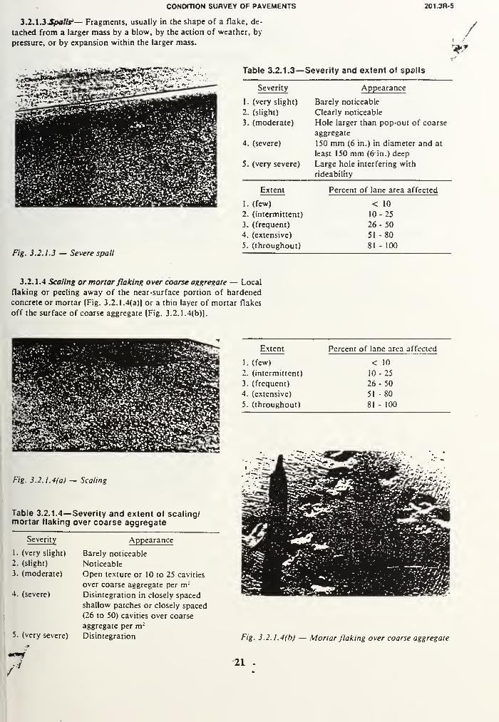
CONDITION SURVEY OF PAVEMENTS 201.3R-5
3. 2.1.3 Spalls'— Fragments, usually in the shape of a flake, de-
tached from a larger mass by a blow, by the action of weather, by-
pressure, or by expansion within the larger mass./
9f
Sgg^sgjg
Table 3.2.1.3—Severity and extent of spalls
Fig. 3.2.1.3 — Severe spall
jggj*"
1
-—Severity Appearance
1. (very slight) Barely noticeable
2. (slight) Clearly noticeable
3. (moderate) Hole larger than pop-out of coarse
aggregate
4. (severe) 150 mm (6 in.) in diameter and at
least 150 mm (6 in.) deep
5. (very severe) Large hole interfering with
rideability
Extent Percent of lane area affected
1. (few) < 10
2. (intermittent) 10-25
3. (frequent) 26-504. (extensive) 51 -80
5. (throughout) 81 - 100
3.2.1.4 Scaling or mortar flaking over coarse aggregate — Local
flaking or peeling away of the near-surface portion of hardened
concrete or mortar [Fig. 3.2.1.4(a)] or a thin layer of mortar flakes
off the surface of coarse aggregate (Fig. 3.2.1.4(b)].
Extent Percent of lane area affected
1. (few) < 10
2. (intermittent) 10- 25
3. (frequent) 26-504. (extensive) 51 -80
5. (throughout) 81 - 100
Fig. 3.2.1.4(a) — Scaling
Table 3.2.1.4— Severity and extent of scaling/mortar flaking over coarse aggregate
Severity Appearance
1. (very slight)
2. (slight)
3. (moderate)
Barely noticeable
Noticeable
Open texture or 10 to 25 cavities
4. (severe)
over coarse aggregate per m ;
Disintegration in closely spaced
shallow patches or closely spaced
(26 to 50) cavities over coarse
5. (very severe)
aggregate per m 2
Disintegration Fig. 3.2.1.4(b) — Mortar flaking over coarse aggregate
21


201.3R-6 MANUAL OF CONCRETE PRACTICE
3.2.1.5 Crazing — Fine, hairline cracks apparently extendingonly through the surface layer and tending to intersect at an angle
of approximately 120 deg forming a chicken-wire pattern.
Table 3.2.1.5—Severity and extent of crazing
E*k
F/g. 3.2.1.5 — Crazing
Severity Appearance
1. (very slight) Barely noticeable in scattered areas
when drying after rain
2. (slight) Barely noticeable over the whole
surface when drying after rain
3. (moderate) Noticeable over the whole area at
all times
4. (severe) Well pronounced in scattered areas
5. (very severe) Well pronounced over the whole
area
Extent
(few)
Percent of lane area affected
1. < 10
2. (intermittent) 10-25
3. (frequent) 26-504. (extensive) 51 -80
5. (throughout) 81 - 100
3.2.1.6 Wheel track wear — Trough-like depression in the wheel
path.
Table 3.2.1.6— Severity and extent of wheel trackwear ^
Severity
1. (very slight)
2. (slight)
3. (moderate)
4. (severe)
5. (very severe)
Fig. 3.2.1.6— Wheel track wear
Extent
1. (few)
2. (intermittent)
3. (frequent)
4. (extensive)
5. (throughout)
Depth of depression, mm0- 5
6- 10
11 - 15
16-20
> 20
Percent of lane length affected
< 10
10-25
26-5051 -80
81 - 100
22


CONDITION SURVEY OF PAVEMENTS 201.3R-7
3.2J2 —Surface deformations
3.2.2.1 Faulting (stepping) .— Differential vertical displacement of
abutting slabs at joints or cracks creating a "step" deformation in the
pavement surface.
Table 3.2.2.1 —Severity and frequency of faulting
(stepping)
Severity
1
.
(very slight)
2. (slight)
3. (moderate)
4. (severe)
5. (very severe) > 15 mm (Vi in.)
Height of fault
Barely noticeable
Noticeable
3-6 mm (Vt-V* in.)
7- 15 mm('/4- 3/« in.)
Fig. 3.2.2.1 — Faulting (stepping)
Frequency
1. (few)
2. (intermittent)
3. (frequent)
4. (extensive)
5. (throughout)
Number of faults per km
< 5
5- 10
11-20
21 -50
> 50
3.2.2.2 Settling (sagging) — The lowering in elevation of sections
of pavement due to the displacement of the support.
Fig. 3.2.2.2 — Settling (sagging)
Table 3.2.2.2.—Severity and frequency of settling
(sagging)
Severity
1. (very slight)
2. (slight)
3. (moderate)
4. (severe)
5. (very severe)
Ridcability
Noticeable change (swaying motion)
Good control of car still present for
driver of vehicle
Fair control of car when driving
over pavement
Poor control when driving over
pavement with driver always having
to anticipate settling ahead
Continuous settling making it a
dangerous situation if driving car at
a speed greater than 60 kmh (40
mph)
Frequency
1. (few)
2. (intermittent)
3. (frequent)
4. (extensive)
5. (throughout)
Number of faults per km1
2
3
4-5.
> 5
23


201.3R-8 MANUAL OF CONCRETE PRACTICE
3.2.2.3 Pumping — The ejection of water, or water and solid ma-terials such as clay or silt, along transverse or longitudinal joints andcracks and along pavement edges.
rs^rr-^ig^i'-^ iirvriTaiitti Table 3.2.2.3— Severity and extent of pumping
— "I'M mjfcCBI
Fig. 3.2.2.3(a) — Pumping (slight)
Severity
(very slight)
2. (slight)
3. (moderate)
4. (severe)
5. (very severe)
Appearance
Small amount of water forced out
of a joint or cracks when trucks
pass over the joint or crack. Nofines observed
Substantial amount of water forced
out when trucks pass over the joint
or crack. No fines observed.
A small amount of pumpedmaterial can be observed near someof the joints or cracks on the
surface of the traffic lane or
shoulder
A significant amount of pumpedmaterials exists on the pavement
surface along the joints or cracks
A large amount of pumped material
exists on the pavement surface
along the joints or cracks
Fig. 3.2.2.3(b) — Pumping (very severe)
Extent
1. (few)
2. (intermittent)
3. (frequent)
4. (extensive)
5. (throughout)
Number of joints or
cracks affected per km*< 5
5 - 10
11 -15
16-25> 25
•If longitudinal joini. number of. affected sections per Km.
24


CONDITION SURVEY OF PAVEMENTS 201.3R-9
3.2.3 — Joint deficiencies
3.2.3.1 Joint creeping — One lane's transverse joint moves ahead
(or behind) the one in the adjacent lane from its original alignment
straight across both lanes.
UflMMMMM^ Table 3.2.3.1—Severity and frequency of joint
creeping
Fig. 3.2.3.1 — Joint creeping
Severity Appearance
1. (very slight) Joint barely out of line
2. (slight) Noticeably out of line
3. (moderate) 12 - 25 mm (Vi-V* in.) out of line
4. (severe) 26 - 50 mm (1-2 in.) out of line
5. (very severe) > 50 mm (> 2 in.) out of line
Frequency Percent of joints showing distress
1 . (few) < 10
2. (intermittent) 10-25
3. (frequent) 26-504. (extensive) 51 -80
5. (throughout) 81 - 100
3.2.3.2 Joint seal loss — Transverse or longitudinal joint seal being
squeezed or pulled out of the joint.
Fig . 3.2.3.2 — Joint seal loss
Table 3.2.3.2-
seal loss
•Severity and frequency of joint
Severity Appearance
1. (very slight) Barely pop-out or breaking
2. (slight) Seal broken and begins to pull out
[up to 300 mm (1 ft)]
3. (moderate) Seal broken and pulled out up to 50
percent of its length
4. (severe) Seal broken and pulled out up to 80
percent of its length
5. (very severe) Seal completely broke and pulled
out more than 80 percent of its
length
Frequency
1. (few)
2. (intermittent)
3. (frequent)
4. (extensive)
5. (throughout)
Percent of joints showing distress
< 10
10-25
26-5051 -80
81 - 100
25


201.3R-10 MANUAL OF CONCRETE PRACTICE
3.2.3.3 Joint sealant (seal) bond loss — A bond failure (or a gap)
between joint sealant (seal) and the face of the joint groove.
"•• ."V"«.*
ft *> £?*.:*£
#v,V
>*v:fft-.<'^i^?s
5&.•• •>' a. -A '4». •<< * .'%
"i '.•/*)>
*.*#'
** -'- _,» - .
F/g. 5.2.5.5 -- Join/ .setf/*
i.*i > '. »^*?» *****
iff
'*. "T-r. .1- #.•:• V
•V > ""A--..'-'*>•$ .;+'**
. '-
Table 3.2.3.3—Severity and extent of joint sealant(seal) bond loss
Severity Bond failure percent of joint length
1. (very slight) < 10
2. (slight) 10-25
3. (moderate) 26~-50
4. (severe) 51 -75
5. (very severe) 76- 100
Extent Percent of joints affected
1. (few) < 10
2. (intermittent) 10-25
3. (frequent) 26-504. (extensive) 51 -80
5. (throughout) 81 - 100
3.2.3.4 Joint sealant cohesion failure — A rupture (crack) within
the sealant itself, parallel to the joint.
Table 3.2.3.4— Severity and extent of joint sealantcohesion failure
Fig. 3.2.3.4 — Joint sealant cohesion failure
Cohesion failure,
Severity percent of joint length
1. (very slight) < 10
2. (slight) 10-25
3. (moderate) 26- 50
4. (severe) 51 -75
5. (very severe) 76- 100
Extent Percent of joints affected
1. (few) < 10
2. (intermittent) 10-25
3. (frequent) 26-504. (extensive) 51 -80
5. (throughout) 81 - 100
26


CONDITION SURVEY OF PAVEMENTS 201.3R-11
3.2.3.5 Joint sealant (seal) extruded — Joint sealant (seal) ex-
truded and flattened by traffic (protruding above joint edges).
Table 3.2.3.5—Severity and frequency of joint
sealant (seal) extrusion
Fig. 3.2.3.5 — Joint sealant extruded
Protrusion above joint edges
Severity (compression seals)
1. (very slight) Barely noticeable < 1 mm (< Vltin »
2. (slight)
in.;
Noticeable I - 3 ('/,» - Vt in.)
3. (moderate) 3 -6 mm ('/i - V* in.)
4. (severe) 6- 12mm('/4 - Vi in.)
5. (very severe) > 12 mm (> Vi in.)
Area covered by flattened sealant
Severity (field molded sealants)
1. (very slight) Barely noticeable
2. (slight) Noticeable
3. (moderate) 0.05 -0.10 m2(0.5 - 1.0 ft
2
)
4. (severe) 0.10-0.25 m2 (1.0 -2.5 ft2
)
5. (very severe) > 0.25 m 2 (> 2.5 ft2
)
Frequency
(few)
Number of distressed joints per km1. < 5
2. (intermittent) 5- 10
3. (frequent) 11 - 15
4. (extensive) 16-25
5. (throughout) > 25
3.2.3.6 Joint sealant impregnated with debris — Incompressible
solids such as aggregate particles embedded in the field-molded seal-
ant.
Fig. 3.2.3.6 — Joint sealant impregnated with debris
Table 3.2.3.6—Severity and extent of joint sealantimpregnated with debris
Severity Appearance
1. (very slight) Several particles no larger than one-
quarter the width of the joint
embedded in the sealant
2. (slight) Several particles not larger than
one-half the width of the joint
embedded in the sealant
3. (moderate) Several particles not larger than
three-quarters the width of the joint
embedded in the sealant
4. (severe) Many particles not larger than
three-quarters the width of the joint
embedded in the sealant
5. (very severe) Many particles, some equal in size
to the width of the joint, embedded
in the sealant
Extent
1. (few)
2. (intermittent)
3. (frequent)
4. (severe)
5. (throughout)
Percent of joints affected
< 10
10-25
26- 50
51 -80
81 - 100
27

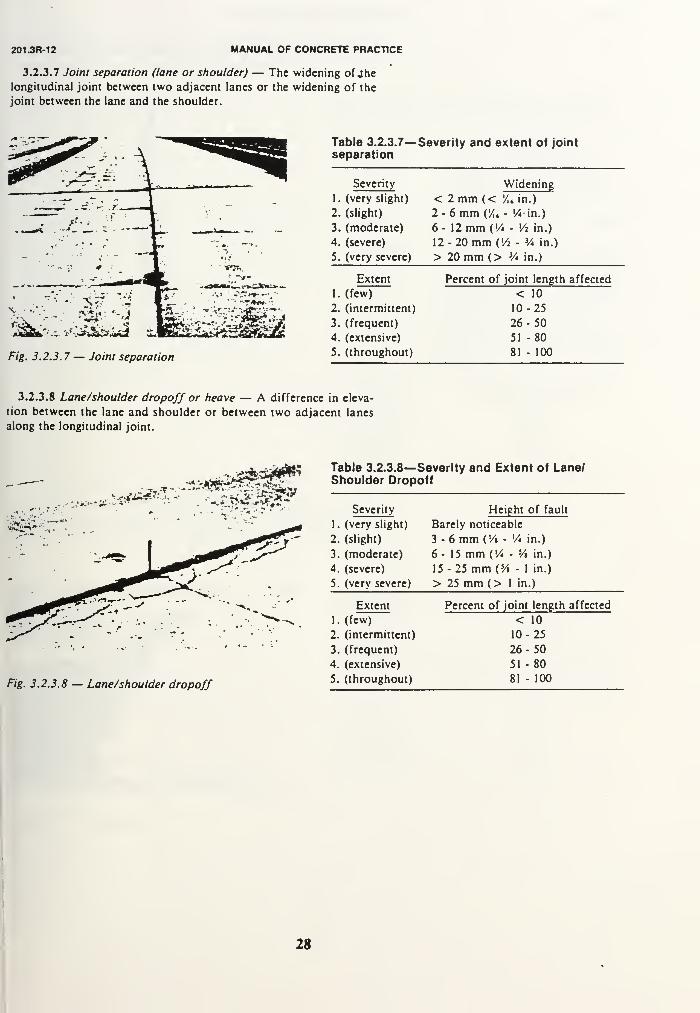
201.3R-12 MANUAL OF CONCRETE PRACTICE
3.2.3.7 Joint separation (lane or shoulder) — The widening ofJhelongitudinal joint between two adjacent lanes or the widening of the
joint between the lane and the shoulder.
J- :- 4"
- * M .'•
Table 3.2.3.7— Severity and extent of joint
separation
Severity
1
.
(very slight)
2. (slight)
3. (moderate)
4. (severe)
Widening
< 2 mm (< '/,„ in.)
2-6mmW,- 14-m.)
6- 12mm('/4 - Vi in.)
12-20mm('/2 - V* in.)
5. (very severe) > 20 mm (> V* in.)
Fig. 3.2.3. 7 — Joint separation
Extent
1. (few)
2. (intermittent)
3. (frequent)
4. (extensive)
5. (throughout)
Percent of joint length affected
< 10
10-25
26-5051 -80
81 - 100
3.2.3.8 Lane/shoulder dropoff or heave — A difference in eleva-
tion between the lane and shoulder or between two adjacent lanes
along the longitudinal joint.
*./i*2£&
*-. >'
Table 3.2.3.8—Severity and Extent of Lane/Shoulder Dropoff
Fig. 3.2.3.8 — Lane/shoulder dropoff
Severity Height of fault
1. (very slight) Barely noticeable
2. (slight) 3-6 mm ('/• - V* in.)
3. (moderate) 6- 15 mm (Vi - Vi in.)
4. (severe) 15-25 mm (Vi - 1 in.)
5. (very severe) > 25 mm (> 1 in.)
Extent Percent of joint length affected
1. (few) < 10
2. (intermittent) 10-25
3. (frequent) 26-504. (extensive) 51 -80
5. (throughout) 81 - 100
28


CONDITION SURVEY OF PAVEMENTS 201.3R-13
3.2.3.9 Joint or crack spoiling — The cracking, breaking, or chip-
ping- of the slab edges within 0.6 m (2 ft) of the transverse or longi-
tudinal joints, or transverse or longitudinal cracks.
15*1 Table 3.2.3.9—Severity and frequency of joint/
crack spading
Fig. 3.2.3.9 — Joint spoiling
Severity Appearance
1. (very slight) Less than 0.6 m (2 ft) long and
extending not more than 0. 1 m (4
in.) from the joint or crack, no
loose or missing pieces
2. (slight) As above but some pieces are loose
or missing
3. (moderate) More than 0.6 m (2 ft) long, broken
into pieces, fray extends more than
0.1 m (4 in.) from the edge of joint
or crack, some small pieces missing
but does not present a safety hazard
4. (severe) As above but large pieces are
missing, presenting a safety hazard
5. (very severe) As above but on both sides of joint
or crack
Frequency
1. (few)
2. (intermittent)
3. (frequent)
4. (extensive)
5. (throughout)
Number of joints per km< 10
10-25
26-5051 -80
> 80
3.2.3.10 Joint/crack failure (blowup, crushing, or compression
failure) — Severe breakdown of slab adjacent to transverse joint or
crack such that patching is required to maintain or restore ridcabil-
ity.
Table 3.2.3.10—Severity and frequency of joint/
crack failure
Severity Appearance
All are severe or very severe because it presents a very
distressing visual effect, very rough ride, and safety
hazard
Frequency Number of distressed joints per kml.(few) 1
2. (intermittent) 2 - 3
3. (frequent) 4-74. (extensive) 8-105. (throughout) > 10
Fig. 3.2.3.10 — Joint failure
29


201.3R-14 MANUAL OF CONCRETE PRACTICE
3.2.4 — Cracks
Cracking is defined as a separation into two or more pans. Crackscan be classified by their orientation in relation to the longitudinal
axis of the pavement.
3.2.4.1 Longitudinal cracks — Cracks which follow a course ap-
proximately parallel to the centerline of the pavement and are gener-
ally quite straight.
Fig. 3.2.4.1 — Longitudinal cracks
Table 3.2.4.1— Severity and extent of longitudinalcracks
Severity Appearance
1. (very slight) < 1 mm ('A, in.) in width
2. (slight) 1 - 10 mm ('/i2 - V» in.) in width
3. (moderate) 10 - 20 mm (3/i - V* in.) in width
4. (severe) 20 - 25 mm (V* - 1 in. in width
5. (very severe) > 25 mm (1 in.) in width with
spalling and/or faulting
Extent
1. (few)
2. (intermittent)
3. (frequent)
4. (extensive)
5. (throughout)
Percent of lane length affected
< 10
10-25
26-5051 -80
81 - 100
3.2.4.2 Meandering cracks — Cracks which wander like a serpent
across the traffic lane and generally occur at a transverse joint.
Table 3.2.4.2— Severity and extent of meanderingcracks
Fig. 3.2.4.2 — Meandering crack
Severity
1. (very slight)
2. (slight)
3. (moderate)
4. (severe)
5. (very severe)
Extent
1. (few)
2. (intermittent)
3. (frequent)
4. (extensive)
5. (throughout)
Appearance
< 1 mm (/„ in.) in width
1 - 10 mm (/,i - Vt in.) in width
10 - 20 mm (H - V* in.) in width
20 - 25 mm (V* -1 in.) in width
> 25 mm (1 in.) in width with spall-
ing and/or faulting
Percent of lane length affected
< 10
10-25
26-5051 -80
81 - 100
30


201.3R-14 MANUAL OF CONCRETE PRACTICE
3.2.4 — Cracks
Cracking is defined as a separation into two or more pans. Crackscan be classified by their orientation in relation to the longitudinal
axis of the pavement.
3.2.4.1 Longitudinal cracks — Cracks which follow a course ap-
proximately parallel to the centerline of the pavement and are gener-
ally quite straight.
Table 3.2.4.1— Severity and extent of longitudinalcracks
Fig. 3.2.4.1 — Longitudinal cracks
Severity Appearance
1. (very slight) < 1 mm (Vu in.) in width
2. (slight) 1 - 10 mm (/) 2 - Vt in.) in width
3. (moderate) 10 - 20 mm (3/» - V* in.) in width
4. (severe) 20 - 25 mm (V* - 1 in. in width
5. (very severe) > 25 mm (1 in.) in width with
spalling and/or faulting
Extent
(few)
Percent of lane length affected
1. < 10
2. (intermittent) 10-25
3. (frequent) 26-504. (extensive) 51 -80
5. (throughout) 81 - 100
3.2.4.2 Meandering cracks — Cracks which wander like a serpent
across the traffic lane and generally occur at a transverse joint.
Table 3.2.4.2— Severity and extent of meanderingcracks
Fig. 3.2.4.2 — Meandering crack
Severity
1. (very slight)
2. (slight)
3. (moderate)
4. (severe)
5. (very severe)
Extent
1. (few)
2. (intermittent)
3. (frequent)
4. (extensive)
5. (throughout)
Appearance
< 1 mm (V,j in.) in width
1 - 10 mm (/„ - Vt in.) in width
10 - 20 mm (Vi - V* in.) in width
20 - 25 mm (V* -1 in.) in width
> 25 mm (I in.) in width with spall-
ing and/or faulting
Percent of lane length affected
< 10
10-25
26-5051 -80
81 - 100
30

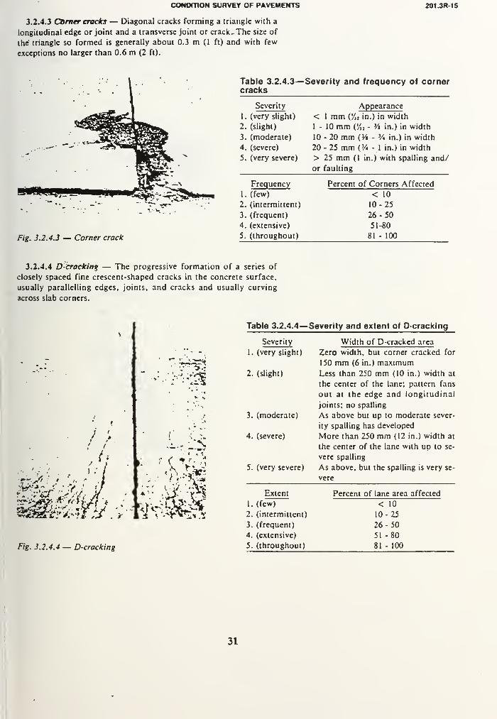
CONOmON SURVEY OF PAVEMENTS 201 3R-15
3.2.4.3 Corner cracks — Diagonal cracks forming a triangle with a
longitudinal edge or joint and a transverse joint or crack- The size of
the triangle so formed is generally about 0.3 m (1 ft) and with few
exceptions no larger than 0.6 m (2 ft).
Table 3.2.4.3—Severity and frequency of cornercracks
Fig. 3.2.4.3 — Corner crack
Severity Appearance
1. (very slight) < 1 mm (Yn in.) in width
2. (slight) 1 - 10 mm (/ji - 3/« in.) in width
3. (moderate) 10-20 mm (Yt - V* in.) in width
4. (severe) 20 - 25 mm (V* - 1 in.) in width
5. (very severe) > 25 mm (1 in.) with spalling and/
or faulting
Frequency Percent of Corners Affected
1. (few) < 10
2. (intermittent) 10-25
3. (frequent) 26-504. (extensive) 51-80
5. (throughout) 81 - 100
3.2.4.4 D-cracking — The progressive formation of a series of
closely spaced fine crescent-shaped cracks in the concrete surface,
usually parallelling edges, joints, and cracks and usually curving
across slab corners.
Fig. 3.2.4.4 — D-cracking
I. » ?V-JI
r^aeki *'-^PS«S
Table 3.2.4.4—Severity and extent of D-cracking
Severity Width of D-crackcd area
1. (very slight) Zero width, but corner cracked for
150 mm (6 in.) maximum2. (slight) Less than 250 mm (10 in.) width at
the center of the lane; pattern fans
out at the edge and longitudinal
joints; no spalling
3. (moderate) As above but up to moderate sever-
ity spalling has developed
4. (severe) More than 250 mm (12 in.) width at
the center of the lane with up to se-
vere spalling
5. (very severe) As above, but the spalling is very se-
vere
Extent
1. (few)
2. (intermittent)
3. (frequent)
4. (extensive)
5. (throughout)
Percent of lane area affected
< 10
10-25
26-50
51 -80
81 - 100
31


201.3R-16 MANUAL OF CONCRETE PRACTICE
3.2.4.5 Transverse cracks — Cracks whieh follow a course approx-
imately at right angles to the pavement centerline.
(:&*!>""
'-*. >v»7W:
F/£. 3.2.4.5(a) — Transverse crack, single
Table 3.2.4.5—Severity and frequency of
transverse cracks
Severity Appearance
1. (very slight) < 1 mm ('/„ in.) in width with no
faulting or spalling
2. (slight) 1 - 10 mm (/„ - M in.) in width
with very slight faulting or spalling
3. (moderate) 10-20 mm (Yt - V* in.) in width
with slight spalling or faulting
(single or multiple cracks)
4. (severe) 20 - 25 mm (Y* - 1 in.) in width
with spalling, faulting (single or
multiple cracks)
5. (very severe) Over 25 mm (1 in.) in width with
spalling, faulting, and debris
trapped in between (single or
multiple cracks)
Frequency
1. (few)
2. (intermittent)
3. (frequent)
4. (extensive)
5. (throughout)
Number of cracks per km
< 10
10-25
26-5051 -80
> 80
Fig. 3.2.4.5(b) — Transverse crack, multiple
32


CONDITION SURVEY OF PAVEMENTS
3.2.4.6 Diagonal cracks — Crack which follows a course approxi-
mately diagonal to the centerline.
201JR-17
Table 3.2.4.6—Severity and frequency of diagonalcracks
Fig. 3.2.4.6 — Diagonal crack
Severity Appearance
1. (very slight) < 1 mm (/)2 in.) in width
2. (slight) 1 - 10 mm (/u-'/i in.) in width
3. (moderate) 10-20 mm (3/i - V* in.) in width
4. (severe) 20 - 25 mm (V* - 1 in.) in width
5. (very severe) > 25 mm (1 in.) in width with
spalling and/or faulting
Frequency Number of cracks per km
1. (few) < 10
2. (intermittent) 10-25
3. (frequent) 26-504. (extensive) 51 -80
5. (throughout) 81 - 100
3.2.4.7 Edge cracks — Arc cracks extending from transverse joint
or crack to the pavement edge generally 0.50 to 0.75 m (2 to 3 ft) in-
ward from the pavement edge and covering an area of 4 to 5 m (15
to 20 ft) from end to end.
Fig. 3.2.4. 7 — Edge crack
Table 3.2.4.7— Severity and frequency of edgecracks
Severity Appearance
1. (very slight) < 1 mm (/,, in.) in width
2. (slight) 1- 10 mm (/,, - '/« in.) in width
3. (moderate) 10 - 20 mm (3/i - V* in.) in width
4. (severe) 20 - 25 mm (V* • 1 in.) in width
5. (very severe) > 25 mm (1 in.) in width with
spalling and/or faulting
Percent of lane
Extent length affected
1. (few) < 10
2. (intermittent) 10-25
3. (frequent) 26- 50
4. (extensive) 51 -80
5. (throughout) 81 - 100
33


201.3R-18 MANUAL OF CONCRETE PRACTICE
3.2.4.8 Punchout — A localized area of the slab that is broken into
pieces. It can take many different shapes and forms but it is usually
defined by a crack and a joint, or two closely spaced cracks (usually
1.5 m apart).
Fig. 3.2.4.8(a) — Punchout, Severity 2
Table 3.2.4.8— Severity and extent of punchout
Severity Appearance
1. (very slight) Maximum three pieces or majority
of cracks up to 1 mm (/u in.) in
width
2. (slight) Maximum four pieces or majority
of cracks up to 20 mm (V* in.) in
width with slight spalling
3. (moderate) Maximum five pieces or majority of
cracks up to 25 mm (1 in.) in width
with spalling
4. (severe) Over five pieces or majority of
cracks up to 25 mm (1 in.) in width
with spalling
5. (very severe) Over five pieces or majority of
cracks over 25 mm (1 in.) in width
with spalling
Extent
1. (few)
2. (intermittent)
3. (frequent)
4. (extensive)
5. (throughout)
Percent of lane area affected
< 10
10-25
26-5051 -80
81 - 100
Fig. 3.2.4.8(b) — Punchout, Severity 5
34


CONDITION SURVEY OF PAVEMENTS 201JR-19
3.2.4.9 Maprcmcking — Interconnected cracks forming networks
of any size and usually similar geometrically to those seen on dried
mud flats.
f S>- i. f. .' •:«..••
Table 3.2.4.9—Severity and extent of mapcracking
Fig. 3.2.4.9 — Map cracking
Severity Appearance
\1. (very slight) Barely noticeable
••"
2. (slight) Clearly visible with no raveling
3. (moderate) Clearly visible with some raveling
K evident
-., •. 4. (severe) Cracks raveled over substantial'• amount of the affected area
5. (very severe) Cracks severely raveled or spalled
Extent Percent of lane area affected
!
1. (few) < 10
2. (intermittent) 10-25
\ 13. (frequent) 26-50
\ •
4. (extensive) 51 -80
5. (throughout) 81 - 100
3.2.4.10 Plastic shrfnkdgVcracks — Cracks that occur in the sur-
face of fresh concrete soon after it is placed and while it is still plas-
tic. They are usually parallel to each other on the order of 300 to 900
mm (1 to 3 ft) apart. They do not usually extend across the entire slab
and do not usually extend through the entire depth of the slab.
Table 3.2.4.10—Severity and extent of plastic
shrinkage cracks
<
Severity Appearance
I. (very slight) Barely noticeable
2. (slight) Clearly visible with no raveling
3. (moderate) Clearly visible with some raveling
evident
4. (severe) Cracks raveled
5. (very severe) Cracks severely raveled or spalled
Extent
(few)
Percent of lane area affected
I. < 10
2. (intermittent) 10-25
3. (frequent) 26-504. (extensive) 51-805. (throughout) 81 - 100
Fig. 3.2.4.10 — Plastic shrinkage cracks
35


201.3R-20 MANUAL OF CONCRETE PRACTICE
3.2.4.11 Cracks at ends of dowels — A transverse crack a short
distance from a transverse joint, usually at the end of joint load
transfer dowels.
Table 3.2.4.11— Severity and extent of cracks at
ends of dowels
Severity Appearance
1. (very slight) < 1 mm (/u in.) in width with no
faulting or spalling
2. (slight) 1-10 mm (/„ - M in.) in width
with very slight spalling or faulting
3. (moderate) 10-20 mm (M - V* in.) in width
with slight spalling or faulting
4. (severe) 20 - 25 mm (V* - 1 in.) in width
with spalling and faulting
5. (very severe) Over 25 mm (1 in.) in width with
spalling, faulting, and debris
trapped in between
Number of distressed
Extent joints per km
1. (few) < 1
2. (intermittent) 2-33. (frequent) 4-74. (extensive) 8- 10
5. (throughout) > 10
3.2.5 — Patches
The presence of remedial measures taken to improve the rideability
of the pavement should also be identified and recorded in Fig. 3.1.
The measures are: hot mix patching, transverse joint repair, pressure
relief joint, precast concrete slab, cold mix patching.
\\
i.
~^. -
Fig. 3.2.5. 1(b) — Hot mix patch
?ig. 3.2.5.1(a) — Precast concrete slab
36

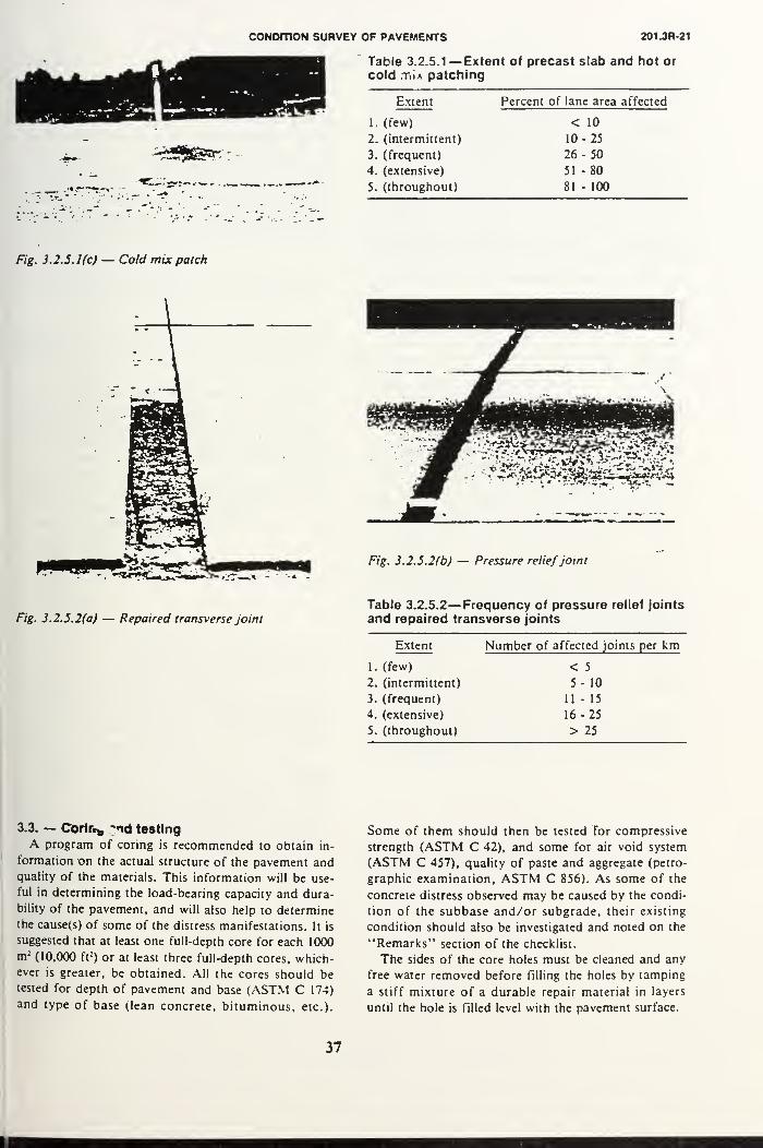
CONDITION SURVEY OF PAVEMENTS 201.3R-21
Table 3.2.5.1— Extent of precast slab and hot or
cold Tiia patching
Extent Percent of lane area affected
1. (few) < 10
2. (intermittent) 10-25
3. (frequent) 26-504. (extensive) 51 -80
5. (throughout) 81 - 100
Fig. 3.2.5.1(c) — Cold mix patch
Fig. 3.2.5.2(a) — Repaired transverse joint
Fig. 3.2.5.2(b) — Pressure reliefjoint
Table 3.2.5.2— Frequency of pressure relief joints
and repaired transverse joints
Extent
1. (few)
2. (intermittent)
3. (frequent)
4. (extensive)
5. (throughout)
Number of affected joints per km
< 5
5- 10
11 - 15
16-25
> 25
3.3. — Corlr.„ "id testing
A program of coring is recommended to obtain in-
formation on the actual structure of the pavement andquality of the materials. This information will be use-
ful in determining the load-bearing capacity and dura-
bility of the pavement, and will also help to determinethe cause(s) of some of the distress manifestations. It is
suggested that at least one full-depth core for each 1000
m :(10,000 ft
2) or at least three full-depth cores, which-
ever is greater, be obtained. All the cores should be
tested for depth of pavement and base (ASTM C 174)
and type of base (lean concrete, bituminous, etc.).
Some of them should then be tested for compressive
strength (ASTM C 42), and some for air void system
(ASTM C 457), quality of paste and aggregate (petro-
graphic examination, ASTM C 856). As some of the
concrete distress observed may be caused by the condi-
tion of the subbase and/or subgrade, their existing
condition should also be investigated and noted on the
"Remarks" section of the checklist.
The sides of the core holes must be cleaned and any
free water removed before filling the holes by tamping
a stiff mixture of a durable repair material in layers
until the hole is filled level with the pavement surface.
37

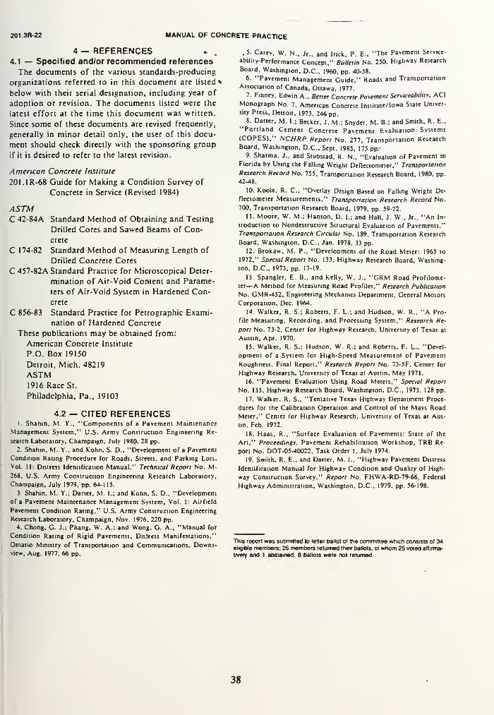
201.3R-22 MANUAL OF CONCRETE PRACTICE
4 — REFERENCES4.1 — Specified and/or recommended references
The documents of the various standards-producing
organizations referred to in this document are listed*
below with their serial designation, including year of
adoption or revision. The documents listed were the
latest effort at the time this document was written.
Since some of these documents are revised frequently,
generally in minor detail only, the user of this docu-
ment should check directly with the sponsoring group
if it is desired to refer to the latest revision.
American Concrete Institute
201.1R-68 Guide for Making a Condition Survey of
Concrete in Service (Revised 1984)
ASTMC 42-84A Standard Method of Obtaining and Testing
Drilled Cores and Sawed Beams of Con-
crete
C 174-82 Standard Method of Measuring Length of
Drilled Concrete Cores
C 457-82A Standard Practice for Microscopical Deter-
mination of Air-Void Content and Parame-
ters of Air-Void System in Hardened Con-
crete
C 856-83 Standard Practice for Petrographic Exami-
nation of Hardened Concrete
These publications may be obtained from:
American Concrete Institute
P.O. Box 19150
Detroit, Mich. 48219
ASTM1916 Race St.
Philadelphia. Pa., 19103
4.2 — CITED REFERENCES1. Shahin. M. Y., "Components of a Pavement Maintenance
Management System." U.S. Army Construction Engineering Re-
search Laboratory. Champaign. July 1980, 28 pp.
2. Shahin, M. Y.. and kohn. S. D., "Development of a Pavement
Condition Rating Procedure for Roads, Streets, and Parking Lois,
Vol. II: Distress Identification Manual," Technical Report No. M-268, U.S. Army Construction Engineering Research Laboratory,
Champaign, July 1979, pp. 64-115.
3. Shahin, M. Y.; Darter, M. I.; and Kohn, S. D., "Development
of a Pavement Maintenance Management System, Vol. 1: Airfield
Pavement Condition Rating," U.S. Army Construction Engineering
Research Laboratory, Champaign, Nov. 1976, 220 pp.4. Chong, G. J.; Phang, W. A.; and Wong, G. A., "Manual for
Condition Rating of Rigid Pavements, Distress Manifestations,"
Ontario Ministry of Transportation and Communications, Downs-view, Aug. 1977, 66 pp.
, 5. Carey, W. N., Jr., and Irick, P. E., "The Pavement Service-
ability-Performance Concept," Bulletin No. 250, Highway Research
Board, Washington, D.C., 1960, pp. 40-58.
6. "Pavement Management Guide," Roads and Transportation
Association of Canada, Ottawa, 1977.7. Finney, Edwin A., Better Concrete Pavement Serviceability. ACI
Monograph No. 7, American Concrete Institute/Iowa State Univer-
sity Press, Detroit, 1973, 246 pp.8. Darter. M. I.; Becker, J. M.; Snyder, M. B.; and Smith, R. E.,
"Portland Cement Concrete Pavement Evaluation Systems
(COPES)," NCHRP Report No. 277, Transportation Research
Board, Washington, D.C., Sept. 1985, 175 ppr9. Sharma, J., and Stubstad, R. N., "Evaluation of Pavement in
Florida by Using the Falling Weight Deflectometer," Transportation
Research Record No. 755. Transportation Research Board, 1980, pp.
42-48.
10. Koole, R. C, "Overlay Design Based on Falling Weight De-
flectometer Measurements," Transportation Research Record No.
700, Transportation Research Board, 1979, pp. 59-72.
11. Moore, W. M.; Hanson, D. I.; and Hall, J. W., Jr., "An In-
troduction to Nondestructive Structural Evaluation of Pavements,"
Transportation Research Circular No. 189, Transportation Research
Board, Washington, D.C., Jan. 1978, 33 pp.
12. Brokaw, M. P., "Development of the Road Meter: 1965 to
1972," Special Report No. 133, Highway Research Board, Washing-
ton, D.C.. 1973, pp. 17-19.
13. Spangler, E. B., and Kelly, W. J., "GRM Road Profilome-
ter—A Method for Measuring Road Profiles," Research Publication
No. GMR-452, Engineering Mechanics Department, General Motors
Corporation. Dec. 1964.
14. Walker. R. S.; Roberts. F. L.; and Hudson, W. R., "A Pro-
file Measuring, Recording, and Processing System," Research Re-
port No. 73-2. Center for Highway Research, University of Texas at
Austin, Apr. 1970.
15. Walker. R. S.; Hudson. W. R.; and Roberts. F. L.. "Devel-
opment of a System for High-Speed Measurement of Pavement
Roughness. Final Report," Research Report No. 73-5F, Center for
Highway Research, University of Texas at Austin. May 1971.
16. "Pavement Evaluation Using Road Meters," Special Report
No. 133. Highway Research Board, Washington. D.C.. 1973. 128 pp.
17. Walker. R. S., "Tentative Texas Highway Department Proce-
dures for the Calibration Operation and Control of the Mays Road
Meter," Center for Highway Research, University of Texas at Aus-
tin. Feb. 1972.
18. Haas, R., "Surface Evaluation of Pavements: State of the
Art," Proceedings, Pavement Rehabilitation Workshop, TRB Re-
port No. DOT-05-40022, Task Order 1. July 1974.
19. Smith, R. E., and Darter, M. I., "Highway Pavement Distress
Identification Manual for Highway Condition and Quality of High-
way Construction Survey," Report No. FHWA-RD-79-66, Federal
Highway Administration, Washington, D.C., 1979, pp. 56-198.
This report was submitted to letter ballot ot the committee which consists ol 34eligible members: 26 members returned their ballots, ol whom 25 voted affirma-
tively and 1 abstained 8 ballots were not returned.
38


APPENDIX BIDENTIFICATION AND CONTROL OFCONSOLIDATION-RELATED DEFECTS
IN FORMED CONCRETE(ACI 309.2R-82)
89


ACI 309.2R-82
Identification and Control of Consolidation-
Related Surface Defects in
Formed Concrete
Reported by ACI Committee 309
ACI Committee Reports. Guides. Standard Practices, and
Commentaries are intended (or guidance in designing, plan-
ning, executing, or inspecting construction and in preparing
specifications. Reference to these documents shall not be
made in the Project Documents. If items found in these doc-
uments are desired to be part of the Project Documentsthey should be phrased in mandatory language and incor-
porated into the Project Documents.
This report provides guidelines for identifying and con-
trolling consolidation-related surface defects in precast or
cast-in-place formed concrete. It includes a summary of di-
rect and indirect causes of such defects, some of which are
frequently attributed to inadequate consolidation practices.
An outline to assist in the reporting on surface conditions
and photographs to illustrate typical concrete surface de-
fects are also included.
Surface defects may be minimized by proper planningduring the design and specification stages. Of equal impor-tance is the employment of properly trained and motivatedsupervisory and construction personnel to achieve the in-
tended concrete finishes and surface textures.
The report emphasizes significant consolidation factors
that prevent surface defects. The reader is cautioned that
concrete is a hand crafted product; therefore, other poten-tial causes may exist beyond those listed in this report.
Keywords: aggregates: amplitude; concretes: consistency; consoli-
dation; discoloration: lormwork (construction!: mix proportioning:placing: preplaced aggregate concrete: quality control; surface de-fects; temperature; vibration: voids; workability.
CONTENTS1.0 — General, p. 309.2R-12.0 — Factors Causing Defects, p. 309.2R-4
2.1 — Design of Structural Members2.2 — Specifications2.3 — Forms2.4 — Properties of Fresh Concrete2.5 — Placement2.6 — Consolidation2.7 — Special Construction Conditions
3.0 — Surface Defects, p. 309.2R-6
3.1 — Honeycomb3.2 — Air Surface Voids3.3 — Form-Streaking3.4 — Aggregate Transparency3.5 — Subsidence Cracking3.6 — Color Variation
3.7 — Sand Streaking3.8 — Layer Lines3.9 — Form Offsets
3.10 — Cold Joints
4.0 — Remedial Procedures, p. 309.2R-9
5.0 — Consolidation of Preplaced AggregateConcrete, p. 309.2R-10
6.0 — Conclusion, p. 309.2R-107.0 — References, p. 309.2R-108.0 — ACI Standards and Reports Cited in
the Text. p. 309.2R-119.0 — Surface Condition Outline,
p. 309.2R-11
1.0 — GENERALA formed, uniformly smooth or lightly textured
surface, essentially free of blemishes and color vari-
ation, is difficult to attain. Since repairs to a defective
surface are costly and seldom fully satisfactory, they
should be avoided by establishing and maintaining
the quality of the concrete operation and by adhering
to acceptable consolidation procedures. Standards for
Copyright 19**2 American Concrete Institute All rights resers
rights ol reproduction .mri use in anv form or hv am means ir
maki.-ig o( conies hv any pholo process, or by an electronic or
device, printed nr written or oral, or recording for sound or \
duclinn or lor use in an\ knowledge or retries. il system or ne
permission :n writing is obtained (rom the copyright proprietor
rd including
iciuding the
mechjnir.il
isual repro
sire, unless
271


I.2R-2 MANUAL OF CONCRETE PRACTICE
TABLE 1 — SUMMARY OF PRIMARY CAUSES OF SURFACE DEFECTS
Defects Causes
Name Description Figure
Design of
Members1
FormsConstruction
Conditions
3
Properties
of Fresh
Concrete
4
Placement
5
Consolidation
6
Stony
surface with
air voids;
lacking in
fines
Small
individual
holes,
irregular,
usually
ranging upto 1 inch (23
mm) in
diameter
Sana or
gravel
textured
areas lacking
cement.
usually
associated
with dark
color on
adjacent
surface
Dark or light
areas of
similar size
and shape to
that of the
coarse
aggregate.
mottled
appearance
Short cracks
varying in
width, moreoften
horizontal
than vertical
1 Highly
congested
reinforcement,
narrow
section,
configuration,
internal
interference,
reinforcement
splices
Battered or
interfering
construction
Interference
to access
Leaking at
joints, severe
grout loss
Hightemperature,
wind.
reinforcement
too close to
forms,
accessibility
problems
Form face
impermeable,poor wetting
characteristics,
formwork too
flexible, uae
of improperform oil
Excessive
form oil. high
temperature
Leaking at
joints, tie
holes, etc.
Too flexible,
high density
surface finish
Poor thermal Insufficient
insulation.
irregular
shape
restraining
settlement.
excessive
absorbency
interval
betweentopout of
columns andplacement of
slab or beam,low humidity
Insufficient
fines, low
workability.
early
stiffening,
excessive
mixing, too
large an
aggregate
(or placing
conditions
Lean, sand
with a high
FM. low
workability,
low FMsand,
excessive
cement or
pozzolan.
particle
degradation,
excessive
sand, high
air content
Low sand
content,
gapgraded.
aggregate
dry or
porous.
excessive
coarse
aggregate,
excessive
slump with
lightweight
concrete
Low sand,
high water
content
Excessive
free fall,
excessive
travel of
concrete in
forms, too
high a lift,
drop chute
omitted or
insufficient
length, too
small a
tremie,
segregation
Too slow.
caused by
inadequate
pumpingrate,
undersized
bucket
Too rapid
Vibrator too
small, too
low a
frequency,
too small an
amplitude.
Short
immersion
time,
excessive
spacing
betweenimmersions.
inadequate
penetration
Too large an
amplitude,
external
vibration
inadequate.
head of
vibrator
partially
immersed
Excessive
amplitude or
Irequency
Excessive or
external
vibration;
over-
vibration of
lightweight
concrete
Insufficient
vibration
272


CONSOLIDATION-RELATED SURFACE DEFECTS 309.2R-3<
TABLE 1 (continued) — SUMMARY OF PRIMARY CAUSES OF SURFACE DEFECTS
Delects Causes
Name Description
Color Variations in
Variation color of the
surface.
visible within
a few hours
after
removing the
formwork
Figure
Design of
Members1
Forms2
Construction
Conditions
3
Properties
of FreshConcrete
4
Placement
5
Consolidation
6
Heavyreinforcing
close to forms
Variation in
absorption
capacity of
surface,
reaction with
form face
Nonuniformcolor of
materials,
inconsistent
grading,
variation in
proportions,
incomplete
mixing.
Calcium
chloride can
cause darkstreaks. Toohigh a
slump. Over-
manipulation
Segregation,
failure to
decrease
consistency
near the top
of deep lift-
Vibrator too
close to
form,
vibration
next to
forms
variable
Sand Variation in
Streaking color or
shade due to
separation of
fine particles
caused by
bleeding
parallel to
the form face
Layer Lines Dark colored Interna]
Lowabsorbency
Low Lean mixture, Too rapid Excessive
temperature, over-sanded for type of vibration.
wet mixtures bleeding
mix. sand
deficient in
fines; low air
content
Insufficient Wet mixture Slow
Excessive
amplitude.
Over-
manipulation
Lack of
scenes interference planning. with placement. vibration.
between high tendency to lack of failure to
concrete temperature bleed equipment penetrate
layers or manpower into previous
layer
Form Offsets Abrupt to 9 Inadequate Rata too Excessive
gradual stiffness or high amplitude.
surface anchorage. nonuniform
irregularities weak forming
material,
irregular
lumber, poor
carpentry
spacing of
immersion
Cold Joints Unintended 10 Internal Poor planning Too dry. Delayed Failure to
discontinuity. interference or insufficient early delivery vibrate into
off-colored backup stiffening lower lift.
concrete equipment Insufficient
vibration
surface finishes are beyond the scope of this report.
Guidance in establishing appropriate standards is of-
fered by the International Council for Building Re-
search (CIB).' The CIB guide classifies four types of
surface finishes required in general concrete work,
namely:
Rough:
Ordinary:
Elaborate:
Special:
No special requirement for finish
Appearance is of some importance
Definite requirements for visual appear-
ance
Highest standards of appearance re-
quired
Concrete construction is not always providing the
degree of perfection necessary to consistently obtain
blemish-free concrete indicated by the special cate-
gory.
To achieve any concrete finish, other than the ten-
tative classification, the designer and contractor must
use materials as well as design and construction prac-
tices that will keep the number of surface defects
within tolerable limits. Surface defects may be traced
to poor consolidation practices and to inadequate de-
sign or construction practices. Undesirable blemishes
and/or defects encountered in concrete construction
indicate a definite need for understanding their
causes and for applying more effective measures to
273


09.2R-4 MANUAL OF CONCRETE PRACTICE
ontrol or eliminate them. This report attempts to
nswer that need. Major emphasis is placed on con-
olidation-related defects.
.0 — FACTORS CAUSING DEFECTSConsolidation-related defects on formed concrete
urfaces include:
(a) Design and Construction-Related Causes
'ifficult placement due to design of a member,
iiproper design and construction of forms,
nproper selection of concrete mixture proportions,
ailure to adjust concrete mixture proportions to suit
lacement condition.
nproper placement practices.
nproper vibration and consolidation practices.
(b) Equipment-Related Causes
nproper Equipmentnproper Equipment Maintenance
Ic) Material-Related Causes
nproper selection of release agent,
ement characteristics,
ariation in mixture components,
lappropriate use of admixtures
pplication procedures for release agents.
Id) Environmental Causes
xtreme weather conditions.
Table 1 summarizes categories of surface defects,
xamples of some of the more common defects are
lustrated in Fig. 1 through 10.
1 — Design of Structural Members
The common problems requiring consideration dur-
g design and planning are congested reinforcement
larticularly splices), narrow sections, complex forms
conditions that require closed top forming, embed-ients, and battered forms.
The manner in which the concrete shall be placed
nd consolidated needs to be visualized for properly
impacted members having the desired appearance,
he designer must have a working knowledge of the
)ncrete placement process. He and the constructor
lould communicate during the early phases of the
>ncreting process. It is important to recognize prob-
m areas in time to take appropriate remedial mea-jres such as: staggering splices, grouping of bars,
lodifying stirrup spacing, and increasing the section
ze. When unfavorable conditions exist which could
>ntribute to substandard surfaces, one or more of
ie following actions should be taken:
1. Redesign the member
2. Redesign the reinforcing steel
3. Specify special mixture modifications to meetnfavorable conditions
4. Utilize mock-up tests to develop a procedure
5. Alert the constructor to critical conditions
2.2 — Specifications
A good specification is essential to insure proper
construction practices. Practical and workable speci-
fications considering unusual and complex job condi-
tions are likely to achieve the desired results.
Specifications must be sufficiently broad in scope
to permit mixture proportion and batch adjustments
needed to produce uniformly workable concrete
which will respond readily to vibration. Concrete maystill vary due to changes in aggregate gradation, air
and concrete temperature, air content, yield, and
batch weights, even though these changes are within
established limits. Approved mixture proportions
may need adjustments to produce the desired con-
crete characteristics and to minimize consolidation
problems. Specifications should require recommendedpractices of mixing, transporting, handling, and plac-
ing that provide optimum consolidation and minimize
chances for surface defects. Also, specifications must
call for vibrators of proper size and characteristics
that are in accordance with ACI 309.
2.3 - Forms
Some surface defects are caused by inadequacies
of the formwork. Examples are leakage at joints, in-
adequate facing material, poorly braced and flexible
forms, improper use of release agents, oversized and
unsealed tie holes. Surface defects also result from
overuse of forms, poor storage practices, inadequate
cleaning, and improper patching and repair of the
forms.
The number of visible surface voids may be re-
duced by using absorptive forms; however, smooth
forms, in combination with the correct selection of a
form release agent, allow air or water voids at
formed surfaces to move upward more freely. ACI303R discusses details of release agents.
Some dry resin type release agents on steel forms
will greatly increase the number of bugholes. An ex-
cessive amount of release agent collecting in the bot-
tom of the form may result in discoloration of the
concrete and may create weak areas. Inadequately
cleaned forms, or those which have been reused too
many times, can contribute significantly to the for-
mation of surface defects. When any of these condi-
tions occur, peeling of the concrete surface may take
place during form removal.
The finish produced by the form as it is stripped
should be observed so that the appropriate corrective
measure can be implemented expeditiously. Inward
sloping forms have a tendency to trap or restrict the
movement of air and water to the surface and in-
crease the occurrence of bugholes.
Form strength, design, and other form require-
ments are covered in ACI 347.
2.4 — Properties of Fresh Concrete
The composition, consistency, workability, and
temperature of fresh concrete have a significant bear-
274


CONSOLIDATION-RELATED SURFACE DEFECTS 309.2R-5
ing on the ease with which a concrete mixture may
be placed and consolidated. For critical surface fin-
ishes, the effect of each ingredient of the mixture
may require special consideration. Mixture propor-
tioning should also consider the placing conditions.
Furthermore, minor mixture adjustments should
be made to maintain workability when the materials
and field conditions change provided that the desired
properties, such as durability, strength, etc., are
maintained.
A review by the designer is essential to determine
strength levels, maximum aggregate size, and slump
requirements for different structural elements. Aconcrete specialist should be called on when difficult
placing conditions exist or when particular concrete
characteristics are desired.
Concrete ingredients should be evaluated and pro-
portions should be selected well in advance of the
concreting operation to achieve the desired proper-
ties for the fresh concrete. When the sand contains
a large amount of particles passing the intermediate
sieve sizes (Nos. 16, 30, 50) (1.2 mm. 600 Mm, 300 pm),
or when a high cement factor or a pozzolan is used,
the resulting mixture may be sticky. Thus the pas-
sage of water may be restricted and air voids mayform at the form-concrete interface. If the sand con-
tains good fractions in the 30-50 range, little bleeding
will occur in the resulting concrete. Also, the work-
ability will tend to be good. As a result, placement
and consolidation of the concrete will be facilitated,
thereby minimizing surface defects.
Aggregates, particularly soft ones, should be eval-
uated for degradation during mixing. Such degrada-
tion can directly affect surface conditions and cause
defects.
Experience indicates that a concrete at a given con-
sistency will generally flow more easily at lower tem-
peratures than at higher temperatures.
When admixtures are used, their effect on place-
ment and consolidation should be evaluated whenmixture proportions are being established. All of the
above factors need to be considered to obtain a con-
crete mixture with the desired composition, consis-
tency, and workability to facilitate its placement and
consolidation.
2.5 - Placement
The objective is to place concrete with a minimumamount of segregation and splashing on the forms.
Once the coarse aggregate is separated from the mor-
tar by poor handling and placement practice, it is
virtually impossible to work the mortar back into the
voids and restore a dense mass by vibration. Segre-
gation and separation causes honeycomb. Splattered
mortar on the form produces color variations and
poor surface texture. Placing concrete too slowly can
produce lift lines or cold joints due to improper con-
solidation. The rate of placement and vibration fac-
tors (intensity, spacing) should be selected to mini-
mize entrapped air in the concrete.
If concrete is deposited in thick lifts of more than
12 in. (305 mm) more air may be trapped than if it
is placed in a thin, even layer of 6 in. (152 mm) thick
or less. Where mixtures of dry or stiff consistencies
are required, the placement should be spread in order
to avoid bugholes and honeycombing.
2.6 — Consolidation
Concrete consists of coarse aggregate particles in
a matrix of mortar and irregularly distributed pock-
ets of entrapped air. The volume of entrapped air
may vary from 5 to 20 percent depending on the
workability of the mixture, size and shape of the
form, amount of reinforcing steel, and method of de-
positing the concrete. The purpose of consolidation is
to remove as much of this entrapped air as practical.
Vibration is the most common method of consoli-
dation. It causes very rapid movement of the con-
crete mixture particles and momentarily liquifies the
mixture, thus reducing the internal friction. Whenvibrated, concrete becomes unstable and through the
action of gravity seeks a lower level and denser con-
dition as entrapped air rises to the surface and is ex
pelled. It compacts laterally against the form ano
around the reinforcing steel. As a field guide, vibra-
tion is continued until the entire batch melts to a uni-
form appearance and the surface just starts to glis-
ten. A film of cement paste shall be discernable
between the concrete and the forms. These visual in-
dicators are not necessarily related to the amount of
vibration needed to obtain good consolidation.
The effectiveness of the vibrator is largely gov-
erned by the head diameter, frequency, and ampli-
tude.
Undervibration is far more common than overvi-
bration. and may be caused by:
1. Use of an undersized or underpowered vibrator
or one not in good working order.
2. Excessive or haphazard spacing of insertions.
3. Inadequate duration of each insertion.
4. Failure of the vibrator to penetrate into the pre-
ceding layer.
5. Vibrator in the wrong position relative to the
form.
Common imperfections resulting from undervibra-
tion are honeycomb, excessive air voids, and layer
lines.
Overvibration can occur when the vibration time
is several times the recommended amount. Overvi-
bration generally is the result of using oversized
equipment, improper procedures, too high slump, or
heavy aggregates. It may result in segregation, ex-
cessive form deflection, sand streaking, form damage,
or loss of almost all of the entrained air in the con-
crete; however, the concrete is not likely to be seri-
ously affected by overvibration if a well-proportioned
mixture with a prbper slump is used. The behavior
of fresh concrete during vibration is discussed in ACI
309. 1R.
275


309.2R-6 MANUAL OF CONCRETE PRACTICE
*"":,.•>" • *_
. •>
j .
J*fj£. J — Honeycomb. Fig. 2 — Air surface voids.
2.7 — Special Construction Conditions
No matter how carefully a concrete finish is spec-
ified, the resultant quality depends on careful con-
struction site organization and the use of well-trained
and skilled workmen. Competent supervision is es-
sential to assure that the construction forces properly
handle and assemble the forms and methodically
place and consolidate the concrete.
Formed concrete surfaces- under boxouts and bat-
tered forms require special considerations for place-
ment. The mixture may have to be adjusted to pro-
duce a readily flowable concrete that is capable of
completely filling the formed area. For large surface
areas, it may be necessary to cut holes in a batteredform to provide access for vibrating the concrete.
With thin lifts and careful vibration, the air and wa-ter bubbles can be drawn up the side of the form.
Experience shows that sloped concrete steeper thanabout 20 deg should be formed and the concrete thor-
oughly vibrated to minimize surface voids. Slopingforms at angles about 45 deg or less may be erectedas temporary forms that are removed for later handfinishing of the concrete.
Large mass concrete sections placed in irregularly
shaped forms may have surface defects due to non-
uniform or widely spaced locations for elephant
trunks, pipes, or chutes. Thoughtless procedures can
cause the concrete to build up in piles. This will pro-
mote segregation, cold joints, layer lines, and subsid-
ence cracks. Placing methods should be well planned
by the constructor.
3.0 — SURFACE DEFECTSThe most serious defects resulting from ineffective
consolidation procedures are: honeycomb, subsidence
cracks, layer lines, and excessive surface voids. Adetailed description of defects and their causes is
listed in Table 1.
3.1 — Honeycomb
(Fig. 1) is a surface condition of irregular voids due
to failure of the mortar during vibration to effectively
fill the spaces among coarse aggregate spaces. Wherebridging of the aggregate particles, or stiffness of the
mixture is a cause of honeycomb, vibration may assist
in overcoming the bridging or to change the flowa-
bility of the concrete. Factors that may contribute to
honeycombing are: congested reinforcement, insuffi-
cient paste content, improper sand-aggregate ratio,
improper placing techniques, and difficult construc-
tion conditions.
276


> >. i,"
CONSOUDATIOM-HELATED SURFACE DEFECTS
• 7* :.h . &«
309.2R-7
okT
o-"4::^
'
.1
F/£. J - Form-streaking.
v'' >-- -v**-'- **>* -«"-*-
.-•. » •*. ^e. - "Si V ? -"•
F/y. 4 - Aggregate transparency
Fig. 5 — Subsidence cracking. Fig- 6 — Color variation.
277


309.2R-6 MANUAL OF 'CONCRETE PRACTICE
•~\
Fig. 7 — Sand streaking.
">S».
Fig. 8 — Layer lines.
3.2 - Air Surface Voids (Bugholes)
(Fig. 2) on vertical faces are caused by air bubbles
entrapped between the concrete mass and the form,
especially in sticky, or stiff concrete mixtures of low
workability which may have an excessive sand and/
or air content/ Also, the use of vibrators of too large
an amplitude or when the vibrator head is only par-
tially submerged may result in increased void for-
mation. Air voids vary in size from microscopic to
about 0.5 in. (12.7 mm). Rarely will water create
bugholes on formed surfaces which manifests itself in
other textural defects such as bleeding channels or
sand streaks. Bleed water voids can form at the top
of a column and on battered formed surfaces. Re-
medial procedures discussed later can greatly reduce
such blemishes.
3.3 - Form-Streaking
(Fig. 3) results from mortar leaking at form joints
and is frequently aggravated by overvibration using
vibrators that are too powerful, or using forms that
are too weak or ones that vibrate excessively during
consolidation. Placing excessively wet mixtures or
high-slump concrete will result in the wash out of
more mortar through tie holes and loose fitting forms
than placement of a low slump concrete mixture.
3.4 — Aggregate Transparency
(Fig. 4) may result from the use of concrete mix-
tures with low sand content, dry or porous aggre-
gates, high density or glossy form surfaces, or high
slump with some lightweight and normal weight ag-
gregates.
3.5 — Subsidence Cracking
(Fig. 5) results from the development of tension
when the concrete mechanically settles after or near
initial set. The cracks are caused by concrete which
is not capable of bridging. They may occur whenthere is an insufficient interval between topout of
concrete in columns and placement of concrete for
slabs or beams. They may also occur adjacent to
blockouts. To prevent this type of cracking, the con-
crete should be revibrated in these areas about 1 hr
after placement.
3.6 — Color Variation
(Fig. 6) may occur within a placement if the con-
crete is not uniform or is incompletely mixed. Vibra-
tors inserted too close to the form destroy the part-
ing agent or mar the form surface. External vibration
used haphazardly may also cause color variation. Fur-
thermore, color variations may also result from non-
uniform absorption and /or nonuniform application of
the release agent.
3.7 - Sand Streaking
(Fig. 7) is caused by heavy bleeding along the form.
It frequently results from the use of harsh, wet mix-
tures deficient in cement paste or mixtures contain-
278


CONSOLIDATION-RELATED SURFACE DEFECTS 3092R-9
•'
'•.' 1
&F/g. 9 — Form offsets. Fig. 10 — Co/d joints.
ing poorly graded aggregates — particularly those
deficient in No. 50 to No. 100 (300 to 150 pm) and
smaller sizes. Sand streaking is controlled by assur-
ing tight forms, well-graded fines, and low bleeding
through proper mixture proportioning. Although the
characteristics of portland cement and fly ash. if
used, have some influence on bleeding, the grading of
the fine aggregate, and the properties of the grout
fluidifiers are of greater importance. Streaking ten-
dencies are amplified as the proportion of sand to ce-
menting materials increase, as in lean mixtures.
3.8 — Layer Lines
(Fig. 8) are the dark horizontal lines on formed sur-
faces indicating the boundary between concrete
placements caused by stiffening of the lower level or
insufficient consolidation due to lack of penetration
into the lower level with the vibrator.
3.9 - Form Offsets
(Fig. 9) are caused by inadequate stiffness or an-
chorage of the forms and can be aggravated by too
high a rate of placement and/or using too powerfula vibrator.
3.10 - Cold Joints
(Fig. 10) frequently occur in concrete due to poor
planning, insufficient backup equipment, stiffening of
the in-place concrete mixture, and an inability to vi-
brate into lower lifts.
4.0 — REMEDIAL PROCEDURESA number of studies have been made to achieve
better consolidation resulting in fewer surface
voids. 41 To minimize the size and number of surface
voids the following practices should be followed:
• Vibration period of sufficient duration
• Vibrator insertions properly spaced and over-
lapped and the vibrator removed slowly
• Each concrete layer consolidated from the bot-
tom upward• Increased vibration periods when using im-
permeable forms
•Avoidance of inward sloping forms and other com-
plex design details
• Limited depth of lifts
• Vibrator penetration into the previous lift
Surface air voids can be minimized by the use.
where practical, of a 2'/z in. (64 mm) diameter vibra-
279


309.2R-10 MANUAL OF CONCRETE PRACTICE
tor of high frequency with medium to low amplitude.
The vibrator should be immersed in the concrete
around the perimeter of the form without touching
the form wall. Form vibration may be used to sup-
plement the internal vibration. An alternate proce-
dure is to use a high frequency, low amplitude form
vibrator. Vibration procedures should be evaluated
at the beginning of a project to determine the vibra-
tion time for each type of vibrator for a given mix-
ture.
Revibration may also reduce concrete surface
voids, which can be accomplished where voids are
most prevalent. It will be most effective if revibration
is delayed as late as possible in the setting period of
the concrete. Greater benefits are obtained from the
wetter concrete mixtures, especially in the top few
feet of a placement where air and water voids are
most prevalent. Revibration should not be applied
routinely, however, and only if special form design is
provided.
5.0 - CONSOLIDATION OF PREPLACEDAGGREGATE CONCRETEThe causes and cures of defects in concrete pro-
duced by the preplaced aggregate concrete method'
(PA) are different from conventionally mixed and
placed concrete in certain aspects. Also, refer to ACI304.1R.
The rate of grout rise in preplaced aggregate
should be limited to an average of 1 ft-per-min (0.3
m/min) with a maximum of 2 ft-per-min (0.6 m/min).
If the supply is too rapid, the grout will rise faster
through the large voids and cascade into the smaller
ones, trapping air. The result is spotty honeycomb-ing. To avoid the occurrence of layer lines, the lower
ends of the grout inserts should always be maintained
at least 1 to 2 ft (0.3 to 0.6 m) below the grout sur-
face.
Grout will not penetrate pockets of fine aggregate;
fines that collect against side or bottom forms will
produce honeycombing. Also, care should be taken to
insure that coarse aggregate fills the space betweenreinforcement and forms. Large surface areas of
grout not subdivided by coarse aggregate may showcrazing from drying shrinkage.
Coarse aggregate should be saturated when placed
and at the time it is grouted. If rewetting in the
forms is required, a fog spray may be applied spar-
ingly. Larger quantities of water will wash fines to
the bottom, resulting in a poor surface or honeycomb.Forms vibrated lightly with external vibrators per-
mit the grout to cover the points of coarse aggregatein contact with the form. Overvibration of the formshould be avoided, however, as it will induce bleeding
which may result in sand streaking.
Where the appearance of formed surfaces is im-
portant, a test section of comparable height should
be produced, the surface examined, and adjustmentsmade to grading, placing, and consolidation proce-
dures to obtain an acceptable result.
6.0 - CONCLUSIONFaulty design and construction practices can result
in defects in formed concrete surfaces. To keep these
defects within tolerable limits, an awareness of their
causes and their cures is essential. The causes of
these defects may lie in materials selection, place-
ment, consolidation, workmanship, initial design con-
cepts, or specifications. In general, to obtain a C.I.B.
finish of elaborate or special category requires the
services of a concrete specialist who can anticipate
complex placing problems and who will provide spec-
ifications and instruction. Finally, the execution of
the work by well-trained work crews under compe-
tent supervision will ensure a concrete surface meet-
ing the requirements of the owner or designer.
7.0 — REFERENCES1. "Tolerances on Blemishes of Concrete," CIB Re-
port No. 24, International Council for Building Re-
search Studies and Documentation, Rotterdam, 1975,
8 pp.
2. ACI Committee 309, "Recommended Practice for
Consolidation of Concrete (ACI 309-72)(Reaffirmed
1978)," American Concrete Institute. Detroit, 1972, 40
pp. Also, ACI Manual of Concrete Practice, Part 2.
3. ACI Committee 303, "Guide to Cast-in-Place Ar-
chitectural Concrete Practice." (ACI 303R-74). Amer-ican Concrete Institute, Detroit, 1974, 30 pp. Also,
ACI Manual of Concrete Practice, Part 3.
4. ACI Committee 347, "Recommended Practice for
Concrete Formwork (ACI 347-78)," American Con-
crete Institute. Detroit. 1978. 37 pp. Also. ACI Man-ual of Concrete Practice, Part 2.
5. Shilstone, James M., "Surface Blemishes in
Formed Concrete." Proceedings, RILEM/ASTM/CIBSymposium on Performance Evaluation of External
Vertical Surfaces of Buildings (Otaniemi, Espoo,
Aug.-Sept. 1977), Technical Research Centre of Fin-
land, Espoo, 1977, pp. 3-7.
6. Stamenkovic, Hrista, "Surface Voids Can Be
Controlled," Concrete Construction, V. 18, No. 12,
Dec. 1973. pp. 597-598. 600.
7. Samuelson, Paul, "Voids in Concrete Surfaces,"
ACI JOURNAL. Proceedings V. 67, No. 11. Nov. 1970,
pp. 868-874.
8. Reading, Thomas J., "The Bughole Problem,"
ACI JOURNAL. Proceedings V. 69, No. 3. Mar. 1972,
pp. 165-171.
9. ACI Committee 304, "Preplaced Aggregate Con-
crete for Structural and Mass Concrete," (ACI
304.1R-69), American Concrete Institute, Detroit,
1969, 13 pp. Also, ACI Manual of Concrete Practice,
Part 2.
10. King, John C, "Special Concretes and Mor-
tars," Handbook of Heavy Construction, 2nd Edition,
McGraw-Hill Book Company, New York, 1971, pp. 22-
1 to 22-17.
280

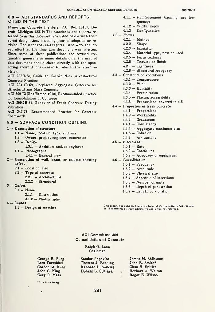
CONSOUDATION-OELATED SURFACE DEFECTS 309.2R-11
8.0 — ACI STANDARDS AND REPORTSCITED IN THE TEXT(American Concrete Institute, P.O. Box 19150, De-
troit, Michigan 48219) The standards and reports re-
ferred to in this document are listed below with their
serial designation, including year of adoption or re-
vision. The standards and reports listed were the lat-
est effort at the time this document was written.
Since some of these publications are revised fre-
quently, generally in minor details only, the user of
this document should check directly with the spon-
soring group if it is desired to refer to the latest re-
vision.
ACI 303R-74, Guide to Cast-In-Place Architectural
Concrete Practice
ACI 304.1R-69, Preplaced Aggregate Concrete for
Structural and Mass Concrete
ACI 309-72 (Reaffirmed 1978). Recommended Practice
for Consolidation of Concrete
ACI 309.1R-81, Behavior of Fresh Concrete During
Vibration
ACI 347-78, Recommended Practice for Concrete
Formwork
9.0— SURFACE CONDITION OUTLINE
1 — Description of structure
1.1 — Name, location, type, and size
1.2 — Owner, project engineer, contractor
1.3 — Design
1.3.1 — Architect and/or engineer
1.4 — Photographs
1.4.1 — General view
2 — Description of wall, beam, or column showingdefect
2.1 — Location, size
2.2 — Type of concrete
2.2.1 - Architectural
2.2.2 - Structural
3 - Defect
3.1 — Name3.1.1 — Description
3.1.2 - Photographs4 — Causes
4.1 — Design of member
4.2 -
4.1.1 — Reinforcement (spacing and fre-
quency)
4.1.2 - Width, depth
4.1.3 — Configuration
Forms4.2.1 - Method4.2.2 - Shape4.2.3 — Insulation
4.2.4 — Material type, new or used
4.2.5 — Form coatings
4.2.6 — Texture or finish
4.2.7 - Tightness
4.2.8 — Structural Adequacy4.3 — Construction conditions
4.3.1 — Temperature
4.3.2 - Wind4.3.3 - Humidity
4.3.4 — Precipitation
4.3.5 — Placing accessibility
4.3.6 — Precautions, covered in 4.5
4.4 — Properties of fresh concrete
4.4.1 — Proportions
4.4.2 - Workability
4.4.3 — Gradations
4.4.4 — Consistency
4.4.5 — Aggregate maximum size
4.4.6 — Cohesion
4.4.7 — Air content
4.5 — Placement
4.5.1 - Rate
4.5.2 — Conditions
4.5.3 — Adequacy of equipment
4.6 — Consolidation
4.6.1 — Frequency
4.6.2 - Amplitude
4.6.3 — Physical size
4.6.4 — Schedule of insertions
4.6.5 — Number of units
4.6.6 — Depth of penetration
4.6.7 — Length of vibration
This report wu submitted to letter ballot ol the committee which consists
o( IS members: 14 were affirmative and 1 was not returned.
George R. BurgLars Forssblad
Gordon M. KiddJohn C. KingGary R. Mass
'Task force leader
ACI Committee 309
Consolidation of Concrete
Ralph O. LaneChairman
Sandor Popovics
Thomas J. Reading
Kenneth L. Saucier
Donald L. Schlegel
James M. Shilstone
John R. Smith*Clem H. Spitler
Herbert A. WeltonRoger E. Wilson
281


APPENDIX CCAUSES, EVALUATION, AND REPAIR
OF CRACKS IN CONCRETE STRUCTURES(ACI 224.1R-89)
101


ACI 224.1 R-89
Causes, Evaluation, and Repair of Cracks in Concrete
Structures
Reported by ACI Committee 224
ACI Committee Reports, Guides, Standard Practices, and
Commentaries are intended for guidance in designing, plan-
ning, executing, or inspecting construction and in preparing
specifications. Reference to these documents shall not be madein the Project Documents. If items found in these documents
are desired to be part of the Project Documents, they should
be phrased in mandatory language and incorporated into the
Project Documents.
The causes of cracks in concrete structures are summarized. The pro-
cedures used to evaluate cracking in concrete and the principal tech-
niques for the repair of cracks are presented. Evaluation techniques
and criteria are described. The key methods of crack repair are dis-
cussed, and guidance is provided for iheir proper application.
keywords: autogenous healing; beams (supports): cement-aggregate reactions;
concrrle construction: concrete pavements; concrete slabs; concretes; consoli-
dation; corrosion; cracking (fracturing): drilling; drying shrinkage: epoxy res-
ins; evaluation; failure: grouting; heat ot hvdranon; mass concrete; mix pro-
portioning; plastics, polymers, and resins; precast concrete: prcsircsscd con-
crete: reinforced concrete: repairs: rcsurtacing; scaling; settlement (structural):
shrinkage: specifications; structural design: tension; thermal expansion; vol-
ume change.
CONTENTSPreface, page 224.1 R-1
Chapter 1 — Causes and control of cracking,
page 224.1 R-1
1.1 — Introduction
1.2 — Cracking of plastic concrete
1.3 — Cracking of hardened concrete
Chapter 2 — Evaluation of cracking,
page 224.1 R-82.1 — Introduction
2.2 — Determination of location and extent of cracking
2.3 — Selection of repair procedures
Chapter 3 — Methods of crack repair,
sage 224.1 R-1
2
3.1 — Introduction
3.2 — Epoxy injection
3.3 — Routing and sealing
3.4 — Stitching
I3.5 — Additional reinforcement
3.6 — Drilling and plugging
3.7 — Flexible sealing
3.8 — Grouting
3.9 — Drypacking
3.10 — Crack arrest
3.11 — Polymer impregnation
3-12 — Overlays and surface treatments
3-13 — Autogeneous healing
Chapter 4 — Summary, page 224.1 R-18
Chapter 5 — References, page 224.1 R-1
8
5.1 — Recommended references
5.2 — Cited references
PREFACE
Cracks in concrete have many causes. They may af-
fect appearance only, or they may indicate significant
structural distress or a lack of durability. Cracks mayrepresent the total extent of the damage, or they maypoint to problems of greater magnitude. Their signifi-
cance depends on the type of structure, as well as the
nature of the cracking. For example, cracks that are
acceptable for building structures may not be accept-
able in water-retaining structures.
The proper repair of cracks depends upon knowing
the causes and selecting the repair procedures that take
these causes into account; otherwise, the repair mayonly be temporary. Successful long-term repair proce-
dure must attack the causes of the cracks as well as the
cracks themselves.
To aid the practitioner in pinpointing the best solu-
tion to a cracking problem, this report discusses the
causes, evaluation procedures, and methods of repair
of cracks in concrete. Chapter I presents a summary of
the causes of cracks and is designed to provide back-
ground for the evaluation of cracks. Chapter 2 de-
scribes evaluation techniques and criteria. Chapter 3
describes the methods of crack repair and includes a
discussion of a number of the techniques that are avail-
able. Many situations will require a combination of
methods to fully correct the problem.
CHAPTER 1 — CAUSES AND CONTROL OFCRACKING
1.1 — Introduction
This chapter presents a brief summary of the causes
of cracks and means for their control. Cracks are cate-
gorized as either occurring in plastic concrete or occur-
Copynght © I989. American Concrete Institute. All rights reserved includ-
ing rights of reproduction and use in any form or by any means, including the
making of copies by any photo process, or by any electronic or mechanical de-
vice, printed or written or oral, or recording for sound or visual reproduction
or for use in any knowledge or retrieval system or device, unless permission in
writing is obtained by the copyright proprietors.
224.1 R-1


R-2 MANUAL OF CONCRETE PRACTICE
]. 1— Typical plastic shrinkage cracking (Reference
9'0-m
* ^ A '*
/.2
—
Crack formed due to obstructed settlementrence 2)
;n hardened concrete.' :In addition to the infor-
m provided here, further details are presented in a
t report by this committee (ACI 224R) and arti-
•y Kelly,1
Price,2Carlson et al.,
3 and Abdun-Nur.4
ional references are cited throughout the chapter.
- Cracking of plastic concrete
.1 Plastic shrinkage cracking — Plastic shrinkage
.ng in concrete (Fig. 1.1) occurs most commonlye exposed surfaces of freshly placed floors and(or other elements with large surface areas) when:ted to a very rapid loss of moisture caused by lowdity, wind, and/or high temperature. Plastic
cage usually occurs prior to final finishing, before
5 starts.
len moisture evaporates from the surface of
y placed concrete faster than it is replaced bywater, the surface concrete shrinks. Due to the
Lint provided by the concrete below the drying:e layer, tensile stresses develop in the weak, stiff-
plastic concrete, resulting in shallow cracks that
ually short and run in all directions. These cracksten fairly wide at the surface. They range from aiches to many feet in length and are spaced from
£•»•' !/«~|1 tca>>
>i»t li» u«i
M/rilltal
Fig. 1.3—Settlement cracking as a function of bar size,
slump, and cover (Reference 5)
a few inches to as much as ten feet (3 m) apart. Plastic
shrinkage cracks may extend the full depth of elevated
structural slabs.
Since plastic shrinkage cracking is due to a differen-
tial volume change in the plastic concrete, successful
control measures require a reduction in the relative vol-
ume change between the surface and other portions of
the concrete.
Steps can be taken to prevent a rapid moisture loss
due to hot weather and dry winds (ACI 224R, ACI302. 1R, ACI 305R). These measures include the use of
fog nozzles to saturate the air above the surface and the
use of plastic sheeting to cover the surface between the
final finishing operations. Windbreaks to reduce the
wind velocity and sunshades to reduce the surface tem-
perature are also helpful, and it is good practice to
schedule flat work after the walls have been erected.
Measures that increase the rate of bleeding may also be
helpful.
1.2.2 Settlement cracking — After initial placement,
vibration, and finishing, concrete has a tendency to
continue to consolidate. During this period, the plastic
concrete may be locally restrained by reinforcing steel,
a prior concrete placement, or formwork. This local
restraint may result in voids and/or cracks adjacent to
the restraining element (Fig. 1.2). When associated with
reinforcing steel, settlement cracking increases with in-
creasing bar size, increasing slump, and decreasing
cover.5 This is shown in Fig. 1.3 for a limited range of
these variables. The degree of settlement cracking maybe magnified by insufficient vibration or the use of
leaking or highly flexible forms.
Proper form design (ACI 347) and adequate vibra-
tion (and revibration), provision of a sufficient time in-
terval between the placement of concrete in columns
and the placement of concrete in slabs and beams (ACI
309.2R), the use of the lowest possible slump, and an
increase in concrete cover will reduce settlement crack-
ing.


1R-2 MANUAL OF CONCRETE PRACTICE
1.1— Typical plastic shrinkage cracking (Reference
1 # A
£".**! •%'-•••:' •^-••J
• *^H
1.2—Crack formed due to obstructed settlementerence 2)
in hardened concrete. 1
:
In addition to the infor-
on provided here, further details are presented in a
it report by this committee (ACI 224R) and arti-
by Keily, 1
Price,2Carlson et al.,
3 and Abdun-Nur. 4
tional references are cited throughout the chapter.
— Cracking of plastic concrete2.1 Plastic shrinkage cracking — Plastic shrinkage<ing in concrete (Fig. 1.1) occurs most commonlyhe exposed surfaces of freshly placed floors and• (or other elements with large surface areas) whenJcted to a very rapid loss of moisture caused by lowidity, wind, and/or high temperature. Plasticikage usually occurs prior to final finishing, beforeig starts.
hen moisture evaporates from the surface of*ly placed concrete faster than it is replaced by1 water, the surface concrete shrinks. Due to theaim provided by the concrete below the dryingice layer, tensile stresses develop in the weak, stiff-
l plastic concrete, resulting in shallow cracks thatisualiy short and run in all directions. These cracks•ften fairly wide at the surface. They range from a
1 nches to many feet in length and are spaced from
»•' tl!«:N«.«<1.)c«)
• •»»• I "It lcail
Fig. 1.3—Settlement cracking as a function of bar size,
slump, and cover (Reference 5)
a few inches to as much as ten feet (3 m) apart. Plastic
shrinkage cracks may extend the full depth of elevated
structural slabs.
Since plastic shrinkage cracking is due to a differen-
tial volume change in the plastic concrete, successful
control measures require a reduction in the relative vol-
ume change between the surface and other portions of
the concrete.
Steps can be taken to prevent a rapid moisture loss
due to hot weather and dry winds (ACI 224R, ACI302. 1R, ACI 305R). These measures include the use of
fog nozzles to saturate the air above the surface and the
use of plastic sheeting to cover the surface between the
final finishing operations. Windbreaks to reduce the
wind velocity and sunshades to reduce the surface tem-
perature are also helpful, and it is good practice to
schedule flat work after the walls have been erected.
Measures that increase the rate of bleeding may also be
helpful.
1.2.2 Settlement cracking — After initial placement,
vibration, and finishing, concrete has a tendency to
continue to consolidate. During this period, the plastic
concrete may be locally restrained by reinforcing steel,
a prior concrete placement, or formwork. This local
restraint may result in voids and/or cracks adjacent to
the restraining element (Fig. 1.2). When associated with
reinforcing steel, settlement cracking increases with in-
creasing bar size, increasing slump, and decreasing
cover.5 This is shown in Fig. 1.3 for a limited range of
these variables. The degree of settlement cracking maybe magnified by insufficient vibration or the use of
leaking or highly flexible forms.
Proper form design (ACI 347) and adequate vibra-
tion (and revibration), provision of a sufficient time in-
terval between the placement of concrete in columns
and the placement of concrete in slabs and beams (ACI
309. 2R), the use of the lowest possible slump, and an
increase in concrete cover will reduce settlement crack-
ing.


CAUSES, EVALUATION, AND REPAIR OF CRACKS 224.1 R-3
1.3 —! Cracking of hardened concrete
1.3.1 Drying shrinkage — A common cause of
cracking in concrete is restrained drying shrinkage.
Drying shrinkage is caused by the loss of moisture from
the cement paste constituent, which can shrink by as
much as 1 percent per unit length. Fortunately, aggre-
gate provides internal restraint that reduces the magni-
tude of this volume change to about 0.05 percent. Onwetting, concrete tends to expand.
These moisture-induced volume changes are a char-
acteristic of concrete. If the shrinkage of concrete could
take place without any restraint, the concrete would not
crack. It is the combination of shrinkage and restraint
(usually provided by another part of the structure or by
the subgrade) that causes tensile stresses to develop.
When the tensile strength of concrete is exceeded, it will
crack. Cracks may propagate at much lower stresses
than are required to cause crack initiation.
In massive concrete elements, tensile stresses are
caused by differential shrinkage between the surface
and the interior concrete. The larger shrinkage at the
surface causes cracks to develop that may, with time,
penetrate deeper into the concrete.
Magnitude of the tensile stresses is influenced by a
combination of factors, including the amount of
shrinkage, the degree of restraint, the modulus of elas-
ticity, and the amount of creep. The amount of drying
shrinkage is influenced mainly by the amount and type
of aggregate and the water content of the mix. Thegreater the amount of aggregate, the smaller the
amount of shrinkage. 6 The higher the stiffness of the
aggregate, the more effective it is in reducing the
shrinkage of the concrete (i.e., the shrinkage of con-
crete containing sandstone aggregate may be more than
twice that of concrete with granite, basalt, or
limestone ). The higher the water content, the greater the
amount of drying shrinkage.8
Surface crazing on walls and slabs is an excellent ex-
ample of drying shrinkage on a small scale. Crazing
usually occurs when the surface layer of the concrete
has a higher water content than the interior concrete.
The result is a series of shallow, closely spaced, fine
cracks.
Drying shrinkage can be reduced by using the maxi-
mum practical amount of aggregate in the mix. Thelowest usable water content is desirable. A procedure
that will help reduce settlement cracking, as well as
drying shrinkage in walls, is reducing water content of
the concrete as the wall is piaced from the bottom to
the top. Using this procedure, bleed water from the
lower portions of the wall will tend to equalize the wa-ter content within the wall. To be successful, this pro-
cedure needs careful control and proper consolidation.
Shrinkage cracking can be controlled by using prop-
erly spaced contraction joints and proper steel detail-
ing. Shrinkage cracking may also be controlled using
shrinkage-compensating cement. It is worthy of notethat in cases where crack control is particularly impor-tant, the minimum requirements of ACI 318 are not al-
ways adequate. These points are discussed in greater
detail in ACI 224R, which contains other construction
practices designed to help control the drying shrinkage
cracking that does occur.
1.3.2 Thermal stresses — Temperature differences
within a concrete structure may be due to cement hy-
dration or changes in ambient conditions or both.
These temperature differences result in differential vol-
ume changes. When the tensile strains due to the dif-
ferential volume changes exceed their tensile strain ca-
pacity, concrete will crack. The effects of temperature
differentials due to the hydration of cement are nor-
mally associated with mass concrete (which can include
large columns, piers, beams, and footings, as well as
dams), while temperature differentials due to changes
in the ambient temperature can affect any structure.
Considering thermal cracking in mass concrete, port-
land cement liberates heat as it hydrates, causing the
internal temperature of concrete to rise during the ini-
tial curing period. The concrete rapidly gains both
strength and stiffness as cooling begins. Any restraint
of the free contraction during cooling will result in ten-
sile stress. Tensile stresses developed during the cooling
stage are proportional to the temperature change, the
coefficient of thermal expansion, the effective modulus
of elasticity (which is reduced by creep), and the degree
of restraint.y~" The more massive the structure, the
greater the potential for temperature differential and
degree of restraint.
Procedures to help reduce thermally induced crack-
ing include reducing the maximum internal tempera-
ture, delaying the onset of cooling, controlling the rate
at which the concrete cools, and increasing the tensile
strain capacity of the concrete. These and other meth-
ods used to reduce cracking in mass concrete are pre-
sented in ACI 207. 1R, ACI 207. 2R. and ACI 224R.
Hardened concrete has a coefficient of thermal ex-
pansion that may range from 4 to 6 x 10 VF (7 to 11
x 10 VC), with an average of 5.5 x 10 VF(10 x 10VC). When one portion of a structure is sub-
jected to a temperature induced volume change, the
potential for thermally induced cracking exists. Design-
ers should give special consideration to structures in
which some portions are exposed to temperature
changes, while other portions of the structure are either
partially or completely protected. A drop in tempera-
ture may result in cracking in the exposed element,
while increases in temperature may cause cracking in
the protected portion of the structure. Temperature
gradients cause deflection and rotation in structural
members; if restrained, senous stresses can result.12,13
Allowing for movement by using properly designed
contraction joints and correct detailing will help alle-
viate these problems.
1.3.3. Chemical reactions — A number of deleteri-
ous chemical reactions may result in the cracking of
concrete. These reactions may be due to the aggregate
used to make the concrete or materials that come into
contact with the concrete after it has hardened.
Some general concepts for reducing adverse chemical
reactions are presented, but only pretesting of the final


3-4 MANUAL Ut- UUNtHETt PHACIlUt
are or extended field experience will determine the
tiveness of a specific measure,
mcrete may crack as the result of expansive reac-
between aggregate containing active silica and al-
5 derived from cement hydration, admixtures, or
nal sources (e.g., curing water, ground water, al-
e solutions stored or used in the finished struc-
I
e alkali-silica reaction results in the formation of
filing gel, which tends to draw water from other
ons of the concrete. This causes local expansion
accompanying tensile stresses, and may eventually
t in the complete deterioration of the structure,
rol measures include proper selection of aggre-
, use of low alkali cement, and use of pozzolans,
i themselves contain very fine, highly active sili-
rhe first measure may preclude the problem from
ring, while the latter two measures have the effect
creasing the alkali to reactive silica ratio, resulting
: formation of a nonexpanding calcium alkali sili-
lam carbonate rocks participate in reactions with alka-
'hich, in some instances, produce detrimental expan-
md cracking. These determined alkali-carbonate reac-
are usually associated with argillaceous dolomitic
:ones which have somewhat unusual textural character-
(ACI 201. 2R). The affected concrete is characterized
etwork pattern of cracks. The reaction is distinguished
he alkali-silica reaction by the general absence of silica
rface deposits at the crack. The problem may be mini-
i by avoiding reactive aggregates, dilution with non-
ve aggregates, use of a smaller maximum size aggre-
and use of low alkali cement (ACI 201. 2R).
fate-bearing waters are a special durability prob-
ar concrete. When sulfate penetrates hydratcd ce-
paste, it comes in contact with hydrated calcium
nate. Calcium sulfoaluminate is formed, with a
quently large increase in volume, resulting in high
tensile stresses causing the concrete to deteriorate.
. II and V portland cement, which are low in tri-
m aluminate, will reduce the severity of the prob-
rhe blended cements specified in ASTM C 595 are
Jseful in this regard. In severe cases, pozzolans,
are known to impart additional resistance to sul-
ttack, could be used after adequate testing,
rimental conditions may also occur from the ap-
ion of deicing salts to the surface of hardenedete. Concrete subjected to water soluble salts
d be amply air entrained, have adequate cover
he reinforcing steel, and be made of high-quality,
ermeability concrete.
: effects of these and other problems relating to
irability of concrete are discussed in greater detail
I201.2R.
: calcium hydroxide in hydrated cement paste will
ine with carbon dioxide in the air to form calciumnate. Since calcium carbonate has a smaller vol-
han the calcium hydroxide, shrinkage will occurnonly known as carbonation shrinkage). This sit-
i may result in significant surface crazing and may
be especially serious on freshly placed surfaces whenimproperly vented combustion heaters are used to keep
concrete warm during the winter months.
With the exception of surface carbonation, very little
can be done to protect or repair concrete that has been
subjected to the types of chemical attack described
above (ACI 201. 2R).
1.3.4 Weathering — The weathering processes that
can cause cracking include (1) freezing and thawing, (2)
wetting and drying, and (3) heating and cooling.
Cracking of concrete due to natural weathering is usu-
ally conspicuous and may give the impression that the
concrete is on the verge of disintegration, even though
the deterioration may not have progressed much below
the surface.
Except in tropical regions, damage from freezing and
thawing is the most common weather-related physical
deterioration. Concrete may be damaged by freezing of
water in the paste, in the aggregate, or in both.14
Damage in hardened cement paste from freezing is
caused by the movement of water to freezing sites and
by hydraulic pressure generated by the growth of ice
crystals.14
Aggregate particles are surrounded by cement paste
which prevents the rapid escape of water. When the ag-
gregate particles are above a critical degree of satura-
tion, the expansion of the absorbed water during freez-
ing may crack the surrounding cement paste and/or
damage the aggregate itself.15- Ib
Concrete is best protected against freezing and thaw-
ing through the use of the lowest practical water-ce-
ment ratio and total water content, durable aggregate,
and adequate air entrainment. Adequate curing prior to
exposure to freezing conditions is also important. Al-
lowing the structure to dry after curing will enhance its
freeze-thaw durability.
Other weathering processes that may cause cracking
in concrete are alternate wetting and drying, and heat-
ing and cooiing. Both of these processes produce vol-
ume changes in concrete. If the volume changes are ex-
cessive, cracks may occur, as discussed in Sections 1.3.1
and 1.3.2.
1.3.5 Corrosion of reinforcement — Corrosion of a
metal is an electro-chemical process that requires an
oxidizing agent, moisture, and electron flow within the
metal; a series of chemical reactions takes place on and
adjacent to the surface of the metal. At points on the
surface, known as anodes, metal atoms lose electrons,
forming ions that go into solution. At other sites on the
surface, known as cathodes, oxygen and water com-
bine with free electrons to form hydroxy! ions (OH* 1
).
The hydroxyl ions move toward the anodes and com-
bine with the metal ions to form hydrous metal oxides.
In the case of steel, iron oxide (rust) forms as a de-
posit at the anodes. On an individual piece of metal,
there may be many anodes and cathodes, and these sites
may be adjacent or widely spaced.
The key to protecting metal from corrosion is to stop
or reverse the chemical reactions. This may be done by
cutting off the supplies of oxygen or moisture or by


CAUSES, EVALUATION, AND REPAIR OF CRACKS 224.1 R-5
supplying excess electrons at the anodes to prevent the
formation of the metal ions (cathodic protection).
Reinforcing steel usually does not corrode in con-
crete because a tightly adhering protective oxide coat-
ing forms in the highly alkaline environment. This is
known as passive protection.
Reinforcing steel may corrode, however, if the alka-
linity of the concrete is reduced through carbonation or
the passivity of this steel is destroyed by aggressive ions
(usually chlorides). Corrosion of the steel produces iron
oxides and hydroxides, which have a volume muchgreater than the volume of the original metallic iron.
17
This increase in volume causes high radial bursting
stresses around reinforcing bars and results in local ra-
dial cracks. These splitting cracks can propagate along
the bar, resulting in the formation of longitudinal
cracks (i.e., parallel to the bar) or spalling of the con-
crete. A broad crack may also form at a plane of bars
parallel to a concrete surface, resulting in the delami-
nation of the surface, a well-known problem in bridge
decks.
Cracks provide easy access for oxygen, moisture, and
chlorides, and thus, minor splitting cracks can create a
condition in which corrosion continues and causes fur-
ther cracking.
Cracks transverse to reinforcement usually do not
cause continuing corrosion of the reinforcement if the
concrete has low permeability. This is due to the fact
that the exposed portion of a bar at a crack acts as an
anode. At early ages, the wider the crack, the greater
the corrosion, simply because a greater portion of the
bar has lost its passive protection. However, for con-
tinued corrosion to occur, oxygen and moisture must be
supplied to other portions of the same bar or bars that
are electrically connected by direct contract or through
hardware such as chair supports. If the combination of
density and cover thickness is adequate to restrict the
flow of oxygen and moisture, then the corrosion pro-
cess is slowed or stopped.17
Corrosion can continue if a longitudinal crack forms
parallel to the reinforcement, because passivity is lost at
many locations, and oxygen and moisture are readily
available along the full length of the bar.
Other causes of longitudinal cracking, such as high
bond stresses, transverse tension (for example, along
stirrups or along slabs with two-way tension), shrink-
age, and settlement, can initiate corrosion.
For general concrete construction, the best protec-
tion against corrosion-induced splitting is the use of
concrete with low permeability. Increased concrete
cover over the reinforcing is effective in delaying the
corrosion process and also in resisting the splitting andspalling caused by corrosion or transverse tension.
18-
19In
the case of large bars and thick covers, it may be nec-
essary to add small transverse reinforcement (while
maintaining the minimum cover requirements) to limit
splitting and to reduce the surface crack width (ACI345).
In very severe exposure conditions, additional pro-tective measures may be required. A number of options
are available, such as coated reinforcement, sealers or
overlays on the concrete, corrosion-inhibiting admix-
tures, and cathodic protection.20 Any procedure that
effectively prevents access of oxygen and moisture to
the steel surface or reverses the electron flow at the an-
ode will protect the steel.
1.3.6 Poor construction practices — A wide variety
of poor construction practices can result in cracking in
concrete structures. Foremost among these is the com-
mon practice of adding water to concrete to improve
workability. Added water has the effect of reducing
strength, increasing settlement, and increasing ultimate
drying shrinkage. When accompanied by a higher ce-
ment content to help offset the decrease in strength, an
increase in water content will also mean an increase in
the temperature differential between the interior and
exterior portions of the structure, resulting in increased
thermal stresses and possible cracking.
Lack of curing will increase the degree of cracking
within a concrete structure. The early termination of
curing will allow for increased shrinkage at a lime when
the concrete has low strength. The lack of hydration of
the cement, due to drying, will result not only in de-
creased long-term strength but also in the reduced du-
rability of the structure.
Other construction problems that may cause crack-
ing are inadequate form supports, inadequate consoli-
dation, and placement of construction joints at points
of high stress. Lack of support for forms or inadequate
consolidation can result in settlement and cracking of
the concrete before it has developed sufficient strength
to support its own weight, while the improper location
of construction joints can result vn cracking at these
planes of weakness.
Methods to prevent cracking due to these and other
poor construction procedures are well known (see ACI224R, ACI 302. 1R, ACI 304, ACI 305R, ACI 308, ACI
309, ACI 345, and ACI 347), but require special atten-
tion by both the constructor and the owner's represen-
tative to insure their proper execution.
1.3.7 Construction overloads — Loads induced dur-
ing construction can be far more severe than those ex-
perienced in service. Unfortunately, these conditions
may occur at early ages when the concrete is most sus-
ceptible to damage and often result in permanent
cracks.
Precast members, such as beams and panels, are
most frequently subjected to this abuse, but cast-in-
place concrete can also be affected. A common error
occurs when precast members are not properly sup-
ported during transport and erection. The use of arbi-
trary or convenient lifting points may cause severe
damage. Lffting eyes, pins, and ot^her attachments
should be detailed or approved by the designer. Whenlifting pins are impractical, access to the bottom of a
member must be provided so that- a strap may be used.
Operators of lifting devices must exercise caution and
be aware that damage may be caused even when the
proper lifting accessories are used. A large beam or
panel lowered too fast, and stopped suddenly, carries


<-t> MANUAL Ur LUNLMtlC mHOIIOC
"icant momentum that translates into an impact
that may be several times the dead weight of the
ber. Another common practice that should be
ed is prying up one corner of a panel to lift it off
d or "break it loose."
len considering the support of a member for ship-
the designer must be aware of loads that may be
ed during transportation. Some examples that oc-
uring shipment of large precast members via trac-
id dolly are jumping curbs or tight highway cor-
torsion due to differing roadway superelevations
•en the dolly and the tractor, and differential ac-
tion of the dolly and the tractor.
:tensioned beams can present unique cracking
?ms at the time of stress release—usually when the
5 are less than one day old. Multiple strands must
:ensioned following a specific pattern, so as not to
unacceptable eccentric loads on the member. If all
|
strands on one side of a beam are released while
rands on the other side are still stressed, cracking
jccur on the side with the fully stressed strands,
cracks are undesirable, but should close with the
e of the balance of the strands,
the case of a T-beam with a heavily reinforced
: and highly prestressed thin web, cracks may de-
al the web-flange junction.
Dther practice that can result in cracks near beamis tack welding embedded bearing plates to the
lg bed to hold them in place during concrete
mcnt. The tack welds arc broken only after
:h prestrcss is induced during stress transfer to
them. Until then, the bottom of the beam is re-
ed while the rest of the beam is compressed.
s will form near the bearing plates if the welds are
'ong.
rrmal shock can cause cracking of steam-cured
:te if it is treated improperly. The maximum rate
>ling frequently used is 70 F (21 C) per hour (AC1R).
21-23 When brittle aggregate is used and the
i capacity is low, this rate should be decreased,
[following this practice, thermally induced crack-
iten occurs. Temperature restrictions should apply
I' entire beam, not just locations where tempera-
Sire monitored. If the protective tarps commonlylo contain the heat are pulled back for access to
tarn ends when cutting the strands, and if the am-i emperatures are low, thermal shock may occur.
:iers are seldom located in these critical areas,
i lar conditions and cracking potential exist with pre-
I >cks, curbs, and window panels when a rapid surface
>,iture drop occurs.
ifelt by some researchers (ACI 517. 2R)24-28
and the
1 ergy Committee29-31 that rapid cooling may cause
kig only in the surface layers of very thick units and
bid cooling is not detrimental to the strength or
b ty of standard precast products.29 One exception is
>vse cracking observed in pretensioned beams sub-
id o cooling prior to detensioning. For this reason,
-r oned members should be detensioned immediately
' k steam-curing has been discontinued.29
Cast-in-place concrete can be unknowingly subjected
to construction loads in cold climates when heaters' are
used to provide an elevated working temperature within
a structure. Typically, tarps are used to cover windowsand door openings, and high volume heaters are oper-
ated inside the enclosed area. If the heaters are located
near exterior concrete members, especially thin walls,
an unacceptably high thermal gradient can result within
the members. The interior of the wall will expand in re-
lation to the exterior. Heaters should be kept awayfrom the exterior walls to minimize this effect. Goodpractice also requires that this be done to avoid local-
ized drying shrinkage and carbonation cracking.
Storage of materials and the operation of equipment
can easily result in loading conditions during construc-
tion far more severe than any load for which the struc-
ture was designed. Unfortunately, there is seldom tight
control over these loads. Damage from unintentional
construction overloads can be prevented only if design-
ers provide information on load limitations for the
structure and if construction personnel heed these limi-
tations.
1.3.8 Errors in design and detailing — The effects of
improper design and/or detailing range from poor ap-
pearance to lack of serviceability to catastrophic fail-
ure. These problems can be minimized only by a thor-
ough understanding of structural behavior (meant here
in the broadest sense). Unfortunately, they often occur
because of insufficient attention on the part of the de-
signer.
Errors in design and detailing that may result in un-
acceptable cracking include use of poorly detailed reen-
trant corners in walls, precast members and slabs, im-
proper selection and/or detailing of reinforcement, re-
straint of members subjected to volume changes caused
by variations in temperature and moisture, lack of ad-
equate contraction joints, and improper design of
foundations, resulting in differential movement within
the structure. Examples of these problems are pre-
sented in References 2 and 32.
Reentrant corners provide a location for the concen-
tration of stress and, therefore, are prime locations for
the initiation of cracks. Whether the high stresses result
from volume changes, in-plane loads, or bending, the
designer must recognize that stresses are always high
near reentrant corners. Well-known examples are win-
dow and door openings in concrete walls and dapped-
end beams, as shown in Fig. 1.4 and 1.5. Additional
properly anchored diagonal reinforcement is required
to keep the inevitable cracks narrow and prevent them
from propagating.
The use of an inadequate amount of reinforcing mayresult in excessive cracking. A typical mistake is to
lightly reinforce a member because it is a "nonstruc-
tural member." However, the member in question
(such as a wall) may be tied to the rest of the structure
in such a manner that it is required to carry a major
portion of the load once the structure begins to de-
form. The "nonstructural element" then begins to
carry loads in proportion to its stiffness. Since this


Fig. 1.4— Typical crack patterns at reentrant corners
(Reference 2)
member is not detailed to act structurally, unsightly
cracking may result even though the safety of the
structure is not in question.
The restraint of members subjected to volumechanges results frequently in cracks. Stresses that can
occur in concrete due to restrained creep, temperature
differentials, and drying shrinkage can be many times
the stresses that occur due to loading. A slab, wall, or
a beam restrained against shortening, even if pre-
stressed, can easily develop tensile stresses sufficient to
cause cracking. Properly designed walls will have con-
traction joints spaced from one to three times the wall
height. Beams will be allowed to move. Cast-in-place
post-tensioned construction that does not permit short-
ening of the prestressed member is susceptible to crack-
ing in both the member and the supporting structure.33
The problem with restraint of structural members is es-
pecially serious in pretensioned and precast membersthat may be welded to the supports at both ends. Whencombined with other problem details (such as reentrant
comers), catastrophic results may be obtained. 32, 34
Improper foundation design may result in excessive
differential movement within a structure. If the differ-
ential movement is relatively small, the cracking prob-
lems may be only visual in nature. However, if there is
a major differential settlement, the structure may not
be able to redistribute the loads rapidly enough, and a
failure may occur. One of the advantages of reinforced
concrete is that, if the movement takes place over a
long enough period of time, creep will allow at least
some load redistribution to occur.
The importance of proper design and detailing will
depend on the particular structure and loading in-
volved. Special care must be taken in the design anddetailing of structures in which cracking may cause amajor serviceability problem. These structures also re-
quire continuous inspection during all phases of con-struction to supplement the careful design and detail-
ing.
Fig. 1.5 — Typical cracking pattern of dapped-end at
service load*
A pertinent example is the category of sanitary struc-
tures, for which ACI Committee 350 has separate de-
sign requirements (ACI 350R) specifically aimed at
providing for well-distributed cracks of minimumwidth. However, even the recommendations of Com-mittee 350 will not insure proper crack control unless
the properties, loadings, environment, and characteris-
tics of the specific structure are taken into account.
1.3.9 Externally applied loads — It is well knownthat load-induced tensile stresses result in cracks in
concrete members. This point is readily acknowledged
and accepted in concrete design. Current design proce-
dures (ACI 318 and AASHTO Standard Specifications
for Highway Bridges) use reinforcing steel, not only to
carry the tensile forces, but to obtain both an adequate
crack distribution and a reasonable limit on crack
width.
Because of the complexity of the analysis, the devel-
opment of load-induced crack control provisions has
historically depended on the analysis of experimental
work. In particular, crack patterns and crack widths
have been investigated in detail for cracks associated
with tensile and flexural stresses. However, shear and
torsion may also cause significant cracking.
Current knowledge of flexural members provides the
basis for the following general conclusions about the
variables that control cracking: Crack width increases
with increasing steel stress, cover thickness, and area of
concrete surrounding each reinforcing bar. Of these,
steel stress is the most important variable. The bar di-
ameter is not a major consideration. The width of a
•From Alan H. Matlock and Timoihy C. Chan. "Design and Behavior ol
Dapped-End Beams.'' Journal. Prestressed Concrete Institute. \ 24. No. 6,
Nov. -Dec. 1979. pp. 28-45.


MANUAL OF CONCRETE PRACTICE
/ i.
.1—Comparator for measuring crack widths
?sy ofEdmund Scientific Co.)
i crack increases with an increasing strain gra-
^etween the steel and the tension face of the
equation considered to best predict the most
>le maximum surface crack width in bending was
>ed by Gergely and Lutz.35 A simplified version
equation follows.
w = 0.076/3/^4 x 10 (1.1)
ch w = most probable maximum crack width,
= ratio of distance between neutral axis and ten-
:ce to distance between neutral axis and centroid
forcing steel (= 1.20 in beams);/ = reinforcing
ress, ksi; d, = thickness of cover from tension
3 center of bar closest thereto, in.; and A = area
crete symmetric with reinforcing steel divided by
r of bars, in.:
.
odification of this equation is used in ACI 318,
limits crack widths to 0.016 in. (0.41 mm) for in-
•xposure and 0.013 in. (0.33 mm) for exterior ex-
:. However, considering the information pre-
in Section 1.3.5 which indicates no connection
:n surface crack width for cracks transverse to
nd the corrosion of reinforcing, these limits do'pear to be justified on the basis of corrosion1.
re have been a number of equations developedstressed concrete members (ACI 244R), without
:thod achieving general acceptance,
maximum crack width in tension members is
than predicted by the expression for flexural
rs. Absence of a strain gradient and compres-•ne in tension members is the probable reason for
ger crack widths.
he basis of limited data, the following expres-is been suggested to estimate the maximum ten-
liick width (ACI 224R).
H' = 0.10/^4 x 10 (1.2)
ural and tensile crack widths can be expected to;e with time for members subjected to either sus-or repetitive loading. Although a large degree ofis evident in the available data, a doubling of
crack width with time can be expected.38"42 Under most
conditions, the spacing of cracks does not change with
time at constant levels of stress. Exceptions occur at
low loads or in beams with high percentages of rein-
forcement, in which case the total number and width of
cracks increase substantially after the loading has be-
gun. 39'
42
Although work remains to be done, the basic princi-
ples of crack control for load-induced cracks are well
understood. Well-distributed reinforcing offers the best
protection against undesirable cracking. A reduced steel
stress, obtained through the use of a larger amount of
steel, will also reduce the amount of cracking. While a
reduced cover will reduce the surface crack width, de-
signers must keep in mind, as pointed out in Section
1.3.5, that cracks (and therefore, crack widths) perpen-
dicular to reinforcing steel do not have a major effect
on the corrosion of that steel, while a reduction in
cover will be detrimental to the corrosion protection of
the reinforcing.
CHAPTER 2 — EVALUATION OF CRACKING2.1 — Introduction
Before proceeding with repairs, an evaluation should
be made to determine the location and extent of crack-
ing, the causes of cracking, and the need for repair.
Calculations can be made to determine stresses due to
applied loads. Drawings, specifications, and construc-
tion and maintenance records should be reviewed. Dis-
crepancies with field data should be noted.
The causes of cracks are discussed in Chapter 1. Adetailed evaluation of observed cracking can determine
which of these causes applies in a particular situation.
Cracks need to be repaired if they reduce the
strength, stiffness, or durability of the structure to an
unacceptable level. Repairs may be required to improve
the appearance of the concrete surface. Cracks also re-
quire repair if the function of the structure is seriously
impaired. In some cases, such as cracking in water-re-
taining structures, the function of the structure will
dictate the need for repair, even if strength, stiffness, or
appearance are not significantly affected. Cracks in
pavements and slabs-on-grade may require repair to
prevent edge spalls, migration of water to the subgrade,
or transmit loads.
2.2 — Determination of location and extent of
cracking
Location and extent of cracking, as well as informa-
tion on the general condition of concrete in a structure,,
can be determined by visual inspection, nondestructive
testing, and tests of cores taken from the structure. In-
formation can also be obtained from drawings, and
construction and maintenance records.
2.2.1 Visual inspection — The location and width of
cracks should be noted on a sketch of the structure. Agrid marked on the surface of the structure can be use-
ful to accurately locate cracks on the sketch.
Crack widths can be measured with an accuracy of
about 0.001 in. (0.025 mm) using a crack comparator,


which is a small hand-held microscope with a scale on
the lens closest to the surface being viewed (Fig. 2.\y.
Locations of observed spalling, exposed reinforcement,
surface deterioration, and rust staining should be noted
on the sketch.
Crack movement can be monitored with mechanical
movement indicators of the types shown in Fig. 2.2.
The indicator, or crack monitor, in Fig. 2.2(a) gives a
direct reading of crack displacement and rotation. Theindicator in Fig. 2.2(b)
43amplifies the crack movement
(in this case, 50 times) and indicates the maximumrange of movement occurring during the measurement
period. Mechanical indicators have the advantage that
they do not require moisture protection. If more de-
tailed time histories are desired, a wide range of trans-
ducers (most notably linear variable differential trans-
formers or LVDTs) and data acquisition systems (rang-
ing from strip chart recorders to computer based sys-
tems) are available.
Sketches can be supplemented by photographs show-
ing the condition of the structure. Guidance for mak-ing a condition survey of concrete in service is given in
ACI 201. 1R.
2.2.2 Nondestructive testing — Nondestructive tests
can be made to determine the presence of internal
cracks and voids and the depth of penetration of cracks
visible at the surface.
Tapping the surface with a hammer or using a chain
drag are simple techniques to identify planar cracking
near the surface. A hollow sound indicates a separation
or crack below the surface.
The presence of reinforcement can be determined us-
ing a pachometer (Fig. 2.3). A number of pachometers
are available that range in capability from merely indi-
cating the presence of steel to those that may be cali-
brated to give either the depth or the size (provided that
the other is known) of the reinforcing.44
In some cases,
however, it may be necessary to remove the concrete
cover to identify the bar sizes, especially in areas of
congested reinforcement.
If corrosion is a suspected cause of cracking, the eas-
iest approach entails the removal of a portion of the
concrete to directly obse.ve the steel. Corrosion poten-
tial can be detected by electrical potential measure-ments using a suitable reference half cell. The mostcommonly used is a copper-copper sulfate half cell
(ASTM C 876 and Reference 45). Use of a half cell also
requires access to a portion of the reinforcing steel.
With properly trained personnel and careful evalua-
tion, it may be possible to detect cracking using ultra-
sonic nondestructive test equipment (ASTM C 597).
The most common technique is through-transmission
testing using a soniscope or other commercially avail-
able equipment.46
-
47 A mechanical pulse is transmitted to
one face of the concrete member and received at the
opposite face, as shown in Fig. 2.4. When access is not
available to opposite faces, transducers may be located
on the same face [Fig. 2.4(a)]. The time taken for the
pulse to pass through the member is measured elec-
tronically. If the distance between the transmitting and
receiving transducers is known, the pulse velocity canbe calculated.
A significant change in measured pulse velocity canoccur if an internal discontinuity results in an increase
in path length for the signal. Generally, the higher the
pulse velocity, the higher the quality of the concrete.
Internal discontinuities can also be detected by the
attenuation of the signal strength if the signal is dis-
played on an oscilloscope [Fig. 2.4(b)]. However, someequipment provides only a digital readout of the pulse
travel time, with no oscilloscope display. If no signal
arrives at the receiving transducer, a significant inter-
nal discontinuity, such as a crack or void, is indicated.
An indication of the extent of the discontinuity can be
obtained by taking readings at a series of positions on
the member.
Ultrasonic equipment should be operated by a
trained technician, and the results should be evaluated
cautiously by an experienced engineer or technician,
because moisture, reinforcing steel, and embeddeditems may affect the results. For example, with fully
saturated cracks, ultrasonic testing will generally be in-
effective. In some cases, it is difficult to discern be-
tween a group of close cracks and a single large crack.
A possible alternative to through-transmission test-
ing is the pulse-echo method.48* which is still in the de-
velopmental stage. A major advantage of this tech-
nique is that access to only one face of the member is
required. A mechanical pulse is generated by impact on
one face of the member. The signal passes through the
member, reflects from the back face of the member,
and is received by a transducer at the front face. For a
solid member, the oscilloscope screen display consists
of a signal corresponding to the original impact and a
signal for the reflected pulse, as shown in Fig. 2.5. In-
termediate signals indicate the presence of internal dis-
continuties. The pulse velocity can also be determined
if the path length is known.
Radiography can be used to detect internal discon-
tinuities. Both x-ray and gamma-ray equipment are
available.46 The procedures are best suited for detecting
crack planes parallel to the direction of radiation; it is
difficult to discern crack planes perpendicular to the
radiation. Gamma-ray equipment is less expensive and
relatively portable compared to x-ray equipment and
therefore appears to he more suitable for field testing.
An important use of nondestructive testing is finding
those portions of the structure that require a more de-
tailed investigation, which may include core tests.
2.2.3 Tests on concrete cores — Significant informa-
tion can be obtained from cores taken from selected lo-
cations within the structure. Cores and core holes af-
ford the opportunity to accurately measure the width
and depth of cracks. In addition, an indication of con-
crete quality can be obtained from compressive strength
•Scanlon. Andrew; Salse, Eduardo A. B.: Corley, W Gene; and Muenow.Richard A.. "Evaluation ol Cracking Using Ulirasonic Test Methods." pre-
sented at the technical session on structural repair ol cracks, ACT Fall Conven-
tion. Detroit. Sept. 1980.

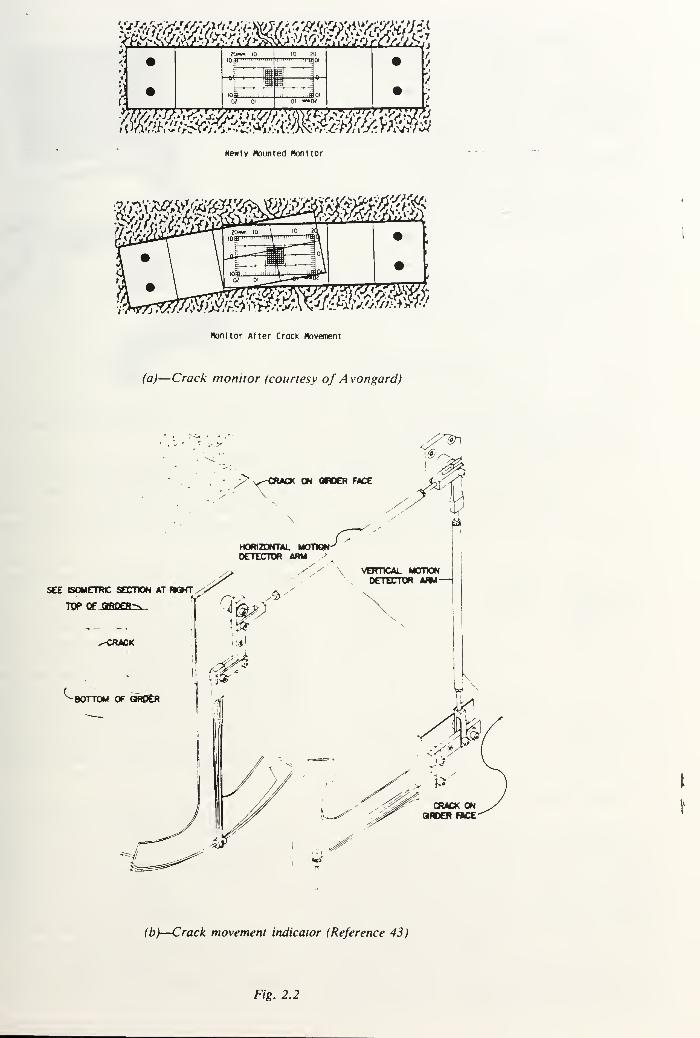
IOJ) '"""in
tan uhim
"Z^T
""' _B°i
itsiliiilliNewly Mounted Hon I tor
l«i^^i^»«
honltor After Crock Movement
fc>
—
Crack monitor (courtesy of A vongard)
^t§r\
r"CRACK ON ORDER FACE
<2"
&•
\
HORIZONTAL MODQN'DETECTOR ARM ,>
SEE BOMETRC SECTION AT W3HT
TOP OF QRO£R-x
^CRACK
LBOTTOM OF ORDER
VERTICAL MOTtCNDETECTOR ARM—
I
(b)—Crack movement indicator (Reference 43)
Fig. 2.2


Fig. 2.3—Pachometer (reinforcing bar locator) (cour-
tesy of James Instruments)
tests. However, cores that contain cracks should not be
used to determine concrete strength.
Core material and crack surfaces can be examined
petrographically to determine the presence of alkali-sil-
ica reaction products or other deleterious substances
(ACI 201. 2R).
Chemical tests for the presence of excessive chlorides
may indicate the potential for corrosion of embedded
reinforcement.
2.2.4 Review of drawings and construction data —Available design and reinforcement placing drawings
should be examined to determine if and where ob-
served cracking can be attributed to inadequate detail-
ing of reinforcement. Calculations can indicate whether
the reinforcement provided is adequate for the applied
loads. Restraint conditions and the presence of con-
traction, expansion, and construction joints should be
considered in calculating the induced tensile stresses. Acomparison should be made between the design loads
and the actual loads acting on the structure.
2.3 — Selection of repair procedures
Based on the careful evaluation of the extent and
cause of cracking, procedures can be selected to ac-
complish one or more of the following objectives:
1. Restore or increase strength;
2. Restore or increase stiffness;
3. Improve functional performance;
4. Provide watertightness;
5. Improve appearance of the concrete surface;
6. Improve durability; and/or
7. Prevent access of corrosive materials to reinforce-
ment.
TransmittingTransducer
ReceivingTransducer
Direct Transmission
Increased Path Length
Due to Discontinuity
Partial Depth Crack
Alternate Configuration
a) Pulse transmitted through member
Amplitude
A Input Signal
Time
Full Strength Signal
Attenuated Signal Output Signal
t = Time delay between Transmitting and Receiving signals
Pulse velocity » d/t
b) Oscl lloscope Signal
pjg 2.4— Ultrasonic testing, through-transmission
technique
Impact or
qEZ^- Oscilloscope •
Screen^r © © a )
i \—Ir
o) Solid nwifter b) Internal Crack
Fig. 2.5— Ultrasonic testing, pulse echo technique
Depending on the nature of the damage, one or
more repair methods may be selected. For example,
tensile strength can be restored across a crack by in-
jecting it with epoxy. However, it may be necessary to
provide additional strength by adding reinforcement or
using post-tensioning. Epoxy injection alone can be
used to restore flexural stiffness if further cracking is
not anticipated (ACI 503R).
Cracks causing leaks in water-retaining structures
should be repaired unless the leakage is considered mi-
nor or there is an indication that the crack is being


by autogenous healing (see Section 3.13). Re-
:o stop leaks may be complicated by a need to
the repairs while the structures are in service and
liquid.
;n cracks result in an unacceptable appearance,
an be repaired. However, the crack location will
: visible, and it is likely that some form of coat-
er the entire surface may be required,
minimize future deterioration due to the corro-
f reinforcement, cracks exposed to a moist envi-
:nt should be sealed.
key methods of crack repair available to accom-
he objectives outlined are described in Chapter 3.
^PTER 3 — METHODS OF CRACK REPAIRintroduction
lowing the evaluation of the cracked structure and
termination of the cause of the cracking, a suit-
epair procedure can be selected. Successful repair
jures take into account the cause of the cracking,
xample, if the cracking was primarily due to
> shrinkage, then it is likely that after a period of
he cracks will stabilize. On the other hand, if the
; are due to a continuing foundation settlement,
will be of no use until the settlement problem is
:ted.
s chapter provides a survey of crack repair meth-
ncluding a summary of the characteristics of the
; that may be repaired with each procedure, the
of structures that have been repaired, and a sum-
of the procedures that are used. Readers are also
;d to ACI 546. 1R and Reference 49, which spe-
ily address the subject of concrete repair.
- Epoxy injection
icks as narrow as 0.002 in. (0.05 mm) can be
;d by the injection of epoxy. The technique gen-
consists of drilling holes at close intervals along
acks, in some cases installing entry ports, and in-
g the epoxy under pressure. For massive struc-
an alternative procedure consists of drilling a se-
f holes [usually 7% in. (22 mm) in diameter] that
epts the crack at a number of locations. Typi-
holes are spaced at 5 ft (1.5 m) intervals.
)xy injection has been successfully used in the Ke-
if cracks in buildings, bridges, dams, and other
: of concrete structures (ACI 503R). However, un-
le crack is dormant (or the cause of cracking is
i/ed, thereby making the crack dormant), it will
ibly recur, possibly somewhere else in the struc-
:lf the cracks are active and it is desired to seal the
I while allowing continued movement at that loca-
lit is necessary to use a sealant or other material
illows that crack to function as a joint. ACI 504Rij bes practices for sealing joints, including joint
li, available materials, and methods of applica-
)
) th the exception of certain specialized epoxies, this
1 ique is not applicable if the cracks are actively
lig and cannot be dried out. While moist cracks
can be injected, contaminants in the crack (including
water) will reduce the effectiveness of the epoxy to
structurally repair the crack.
Epoxy injection requires a high degree of skill for
satisfactory execution, and application of the technique
may be limited by the ambient temperature (ACI
503R). The general procedures involved in epoxy injec-
tion are as follows (ACI 503R):
1. Clean the cracks. The first step is to clean the
cracks that have been contaminated. Oil, grease, dirt,
or fine particles of concrete prevent epoxy penetration
and bonding. Preferably, contamination should be re-
moved by flushing with water or other specially effec-
tive solvent. The solvent is then blown out using com-
pressed air or adequate time is provided for air drying.
2. Seal the surfaces. Surface cracks should be sealed
to keep the epoxy from leaking out before it has gelled.
Where the crack face cannot be reached, but where
there is backfill, or where a slab-on-grade is being re-
paired, the backfill material or subbase material is often
an adequate seal. A surface can be sealed by brushing
an epoxy along the surface of the crack and allowing it
to harden. If extremely high injection pressures are
needed, the crack should be cut out to a depth of '/: in.
(13 mm) and width of about V* in. (19 mm) in a
V-shape, filled with an epoxy, and struck off flush with
the surface. If a permanent glossy appearance along the
crack is objectionable and if high injection pressure is
not required, a strippable plastic may be applied along
the crack. When the job is completed, the dry filler can
be stripped away to expose the gloss-free surface.
3. Install the entry ports. Three methods are in gen-
eral use:
a. Drilled holes-fittings inserted. Historically, this
method was the first to be used, and is often used in
conjunction with V-grooving of the cracks. The method
entails drilling a hole into the crack, approximately lAin. (19 mm) in diameter and Vi to 1 in. (13 to 25 mm)below the apex of the V-grooved section, into which a
fitting such as a pipe nipple or tire valve stem is bonded
with an epoxy adhesive. A vacuum chuck and bit are
useful in preventing the cracks from being plugged with
drilling dust.
b. Bonded flush fitting. When the cracks are not
V-grooved, a method frequently used to provide an en-
try port is to bond a fitting flush with the concrete face
over the crack. This flush fitting has a hat-like cross
section with an opening at the top for the adhesive to
enter.
c. Interruption in seal. Another system of provid-
ing entry is to omit the seal from a portion of the crack.
This method can be used when special gasket devices
are available that cover the unsealed portion of the
crack and allow injection of the adhesive directly into
the crack without leaking.
4. Mix the epoxy. This is done either by batch or
continuous methods. In batch mixing, the adhesive
components are premixed according to the manufac-
turer's instructions, usually with the use of a mechani-
cal stirrer, like a paint mixing paddle. Care must be


Groove cut with sow
or chlDDlng tools — Joint Sealer
a) Original Crack b) Routing c) Sealing
Fig. 3.1—Repair of crack by routing and sealing (Ref-
erence 51)
taken to mix only the amount of adhesive that can be
used prior to commencement of gelling of the material.
When the adhesive material begins to gel, its flow char-
acteristics begin to change, and pressure injection be-
comes more and more difficult. In the continuous mix-
ing system, the two liquid adhesive components pass
through metering and driving pumps prior to passing
through an automatic mixing head. The continuous
mixing system allows the use of fast setting adhesives
that have a short working life.
5. Inject the epoxy. Hydraulic pumps, paint pressure
pots, or air-actuated caulking guns can be used. The
pressure used for injection must be carefully selected.
Increased pressure often does little to accelerate the rate
of injection. In fact, the use of excessive pressure can
propagate the existing cracks, causing additional dam-
age.
If the crack is vertical, the injection process should
begin by pumping epoxy into the entry port at the low-
est elevation until the epoxy level reacnes the entry port
above. The lower injection port is then capped, and the
process is repeated at successively higher ports until the
crack has been completely filled and all ports have been
capped.
For horizontal cracks, the injection should proceed
from one end of the crack to the other in the samemanner. The crack is full if the pressure can be main-
tained. If the pressure cannot be maintained, the epoxy
is still flowing into unfilled portions or leaking out of
the crack.
6. Remove the surface seal. After the injected epoxy
has cured, the surface seal should be removed by
grinding or other means, as appropriate. Fittings andholes at entry ports should be painted with an epoxy
patching compound.In the specific case of delaminated bridge decks,
epoxy injection can be an effective intermediate term
repair procedure.50
In this case, the first, second, and
sixth steps are omitted. The process is terminated at a
specific location when epoxy exits from the crack at
some distance from the injection ports. This procedure
does not arrest ongoing corrosion.
3.3 — Routing and sealing
Routing and sealing can be used on cracks that are
dormant and of no structural significance. This methodinvolves enlarging the crack along its exposed face andtilling and sealing it with a suitable joint sealant (Fig.
Note vorlaole length, location ana
orientation of dogs so that tension
across crack Is distributed In the
concrete rather than concentrated
on a single plane.
— Holes drilled In concrete to
receive dogs. Fill holes withs\ nonsnrlnk grout or eooxv.
Stitching Dogs
Fig. 3.2—Repair of crack by stiching {Reference 51)
3.1). The routing operation may be omitted, but at
some sacrifice in the permanence of the repair.
This is the simplest and most common technique for
crack repair. It can be executed with relatively un-
trained labor (compared to epoxy injection) and is ap-
plicable for sealing both fine pattern cracks and larger
isolated defects. The method will not be effective on an
active crack (for sealing of active cracks, see Section
3.7). Routing and sealing are not applicable lor sealing
cracks subject to a pronounced hydrostatic pressure,
except when sealing the pressure face, in which case
some reduction in the How can be obtained.
The routing operation consists of preparing a groove
at the surface that is sufficiently large to receive the
sealant, using a concrete saw, hand tools, or pneumatic
tools. A minimum surface width of !
j in. (6 mm) is de-
sirable. Repairing narrower grooves is difficult. The
surfaces of the routed joint should be cleaned with an
air jet and permitted to dry before placing the seilant.
The purpose of the sealant is to prevent water from
reaching the reinforcing steel, hydrostatic pressure from
developing within the joint, staining the concrete sur-
face, or causing moisture problems on the far side of
the member.
The sealant may be any of several materials, depend-
ing on how tight or permanent a seal is desired. Epoxy
compounds are often used. Hot-poured joint sealants
work very well when thorough watertightness of the
joint is not required and appearance is not important.
Urethanes, which remain flexible through large tem-
perature variations, have been used successfully in
cracks up to V* in. (19 mm) in width and of consider-
able depth. There are many commercial products, and
the manufacturers should be consulted as to the type
and grade most applicable for the specific purpose and
condition of exposure. The method of placing depends
on the material to be used and should follow the tech-
niques recommended in ACI 504R.
3.4 — Stitching
This method involves drilling holes on both sides of
the crack and grouting in stitching dogs (U-shaped
_


Slab
ACrack
3.3—Reinforcing bar orientation used to effect the re-
(Reference 43)
il units with short legs) that span the crack (Fig.51
Stitching may be used when tensile strength must
established across major cracks. Stitching a crack
s to stiffen the structure, and the stiffening mayituate the overall structural restraint, causing the
rete to crack elsewhere. Therefore, it may be nec-
y to strengthen the adjacent section using external
orcement embedded in a suitable overlay,
te stitching procedure consists of drilling holes on
sides of the crack, cleaning the holes, and anchor-
he legs of the dogs in the holes, with either a non-
lk grout or an epoxy resin-based bonding system,
stitching dogs should be variable in length and ori-
tion or both, and they should be located so that the
on transmitted across the crack is not applied to a
le plane within the section but is spread over an
)acing of the stitching dogs should be reduced at
:nd of cracks. In addition, consideration should be
i to drilling a hole at each end of the crack to blunt
d relieve the concentration of stress,
here possible, stitch both sides of the concrete see-
so that further movement of the structure will not
3r bend the dogs. In bending members, it is possi-
o stitch one side of the crack only. This should be
: on the tension face, uhere movement is occur-
If the member is in a state of axial tension, then
logs must be placed symmetrically, even if excava-
or demolition is required to gain access to opposite
of the section.
itching will not close a crack but can prevent it
i propagating further. Where there is a water prob-i the crack should be made watertight as well as
lied to protect the dogs from corrosion. This repair
:Id be completed before stitching begins. An excep-
should be made in the case of active cracks, where: tructure must be stabilized before being made wa-;ht, because movement at the crack may break the
i rial within the crack.
ie dogs are relatively thin and long, and cannot« much compressive force. Accordingly, if there is ai:ncy for the crack to close as well as to open, the
'; must be stiffened and strengthened, for example,
icasement in an overlay.
JLtension tie
?o) To Correct Cracking of Slab
Through Bolts
Anchorage
Tension TieCrack
b) To Correct Cracking of Beam
Fig. 3.4—Examples of external prestressing (Reference 51)
3.5 — Additional reinforcement
3.5.1 Conventional reinforcement — Cracked rein-
forced concrete bridge girders have been success-
fully repaired using epoxy injection and reinforcing bar
insertion.43, 52, 53
This technique consists of sealing the
crack, drilling holes [V* in. (19 mm) in diameter] at 45
deg to the deck surface and crossing the crack plane at
approximately 90 deg (Fig. 3.3), filling the hole and
crack plane with epoxy pumped under low pressure [50
to 80 psi (342 to 548 kPa)], and placing a reinforcing
bar into the drilled hole. Typically No. 4 or 5 (13 or 16
mm) bars are used, extending at least 18 in. (0.46 m) on
each side of the crack. The epoxy bonds the bar to the
walls of the hole, fills the crack plane, bonds the
cracked concrete surfaces back together in one mono-lithic form, and thus reinforces the section.
A temporary elastic exterior crack sealant is required
for a successful repair. Gel-type epoxy crack sealants
work very well within their elastic limits. Silicone rub-
ber gap sealants work well and are especially attractive
in cold weather or when time is short. The sealant
should be applied in a uniform layer approximately V, t
to V, 2 in. (1.6 to 2.4 mm) thick and should span the
crack by at least V* in. (19 mm) on each side.
The epoxy used to rebond the crack should have a
very low viscosity and a high modulus of elasticity. It
should be capable of bonding to concrete in the pres-
ence of moisture, and it should be 100 percent reactive.
The reinforcing bars can be spaced to suit the needs
of the repair. They can be placed in any desired pat-


0'Form key »l in orecost concrete or mortor oIuqs
sei In Bitumen. Ihe Bitumen is to Break the Bona
between olugs ond nole so tnot oluqs -ill not oe
cracked By suOseauent movement ot tne ooenlno.
If a oortlculdrly good seal is reaulred. drill a
second nole ond oluq xlth Blti/nen olone. uslnq
the tlrst nole as a key and tne second ds d seol.
Hole drilled In stem of Mil. Centered
on ond follonlnq ao«n crack. SWe ot
nole depends on «iotn ot crock, use
?" to 7-\/l' minimum diameter.
Fig. 3.5—Repair of crack of drilling and plugging (Refer-
ence 51)
tern, depending on the design criteria and the location
of the in-place reinforcement.
3.5.2 Prestressing steel — Post-tensioning is often the
desirable solution when a major portion of a member
must be strengthened or when the cracks that have
formed must be closed (Fig. 3.4). This technique uses
prestressing strands or bars to apply a compressive
force. Adequate anchorage must be provided for the
prestressing steel, and care is needed so that the prob-
lem will not merely migrate to another part of the
structure. The effects of the tensioning force (including
eccentricity) on the stress within the structure should be
carefully analyzed. For indeterminate structures post-
tensioned using this procedure, the effects of secondary
moments and induced reactions should be eonsid-
ered.
3.6 — Drilling and plugging
Drilling and plugging a crack consists o\ drilling
down the length of the crack and grouting it to form a
key (Fig. 3.5).
This technique is only applicable when cracks run in
reasonably straight lines and are accessible at one end.
This method is most often used to repair vertical cracks
in retaining walls.
A hole [typically 2 to 3 in. (50 to 75 mm) in diame-
ter] should be drilled, centered on and following the
crack. The hole must be large enough to intersect the
crack along its full length and provide enough repair
material to structurally take the loads exerted on the
key. The drilled hole should then be cleaned, madetight, and filled with grout. The grout key prevents
transverse movement of the sections of concrete adja-
cent to the crack. The key will also reduce heavy leak-
age through the crack and loss of soil from behind a
leaking wall.
If water tightness is essential and structural load
transfer is not, the drilled hole should be tilled with a
resilient material of low modulus in lieu ot grout. If the
keying effect is essential, the resilient material can be
placed in a second hole, the first being grouted.
F?5 * ?•<?
Crock Closed No Bona Breaker with Bona Breoker
Fig. 3.6—Effect of bond breaker
0'o'tP" "o 075^0-00^
Jo"« <^J: <—7 cO O* C700. O
Backup Material —0$o
Sl^S^S^ Bond Breaker
Crack
Fig. 3. 7
—
Repair of crack using flexible surface seal
3.7 — Flexible sealing
Active cracks can be routed out; cleaned by sand-
blast, air-water jet, or both; and tilled with a suitable
field-molded flexible sealant. As nearly as is practical,
the sealant reservoir (slot) formed by routing should
comply with the requirements for width and shape lac-
tor of a joint having equivalent movement.
The selection of a suitable sealant and installation
method should follow those lor equivalent joints (AC'I
504R).
A bond breaker should be provided at the bottom o\
the slot to allow the sealant to change shape without a
concentration o\ stress on the bottom (fig. 3.6). The
bond breaker may be a polyethylene strip, pressure
sensitive tape, or other material which will not bond to
the sealant before or during cure.
Narrow cracks subject to movement, where esthetics
are not important, may be sealed with a flexible sur-
face seal (Fig. 3.7).
By using a bond breaker over the crack, a flexible
joint sealant may be troweled over the bond breaker
providing an adequate bonding area. This is a very
economical procedure and may be used on the interior
of a tank, roofs, or other areas not subject to traffic or
mechanical abuse.
3.8 — Grouting
3.8.1 Portland cement fronting — Wide cracks, par-
ticularly in gravity dams and thick concrete walls, may
be repaired by filling with port land cement grout. The
procedure consists o\ cleaning the concrete along the
crack; installing built-up seats (grout nipples) at inter-
vals astride the crack (to provide a pressure tight con-
tact with the injection apparatus); sealing the crack be-
tween the seats with a cement paint, sealant, or grout;
flushing the crack to clean it and test the seal; and then
grouting the whole area. Cirout mixtures may contain
cement and water or cement plus sand and water, de-


ID MANUAL Ul- LUNLHtlt PHAUTICt
Semicircular pipe (6 s diaa),-
f l*n<je<j #v showi
Cone
concen
Pprior to placementof upper lift.
oncrete placed ' ^Q^}&^~1oncentncally over <^Siir^QoP \nipe «t least ? days d^rS3£a^ f
Holes drilled >n concreteor pegs inserted to hold
pipe in place.
3.8—Crack arrest method of crack repair
K on the width of the crack. However, the wa-
nent ratio should be kept as low as practical to
lize strength and minimize shrinkage. Water re-
or other admixtures may be used to improve the
ties of the grout. For small volumes, a manualon gun may be used; for larger volumes, a pump1 be used. After the crack is filled, the pressure
\ be maintained for several minutes to insure
penetration.
2 Chemical grouting — Chemical grouts consist
jtions of two or more chemicals that combine to
a gel, a solid precipitate, or a foam, as opposed
lent grouts that consist of suspensions of solid
les in a fluid. Cracks in concrete as narrow as
in. (0.05 mm) have been filled with chemical
advantages of chemical grouts include their ap-
lility in moist environments (excess moisture
blc), wide limits of control of gel time, and their
ation in very fine fractures. Disadvantages are the
legree of skill needed for satisfactory use, their
»f strength, and the requirement that the grout
lot dry out in service.
Drypacking
packing is the hand placement of a low water
it mortar followed by tamping or ramming of the
r into place, producing intimate contact between
ortar and the existing concrete.8 Because of the
ater-cement ratio of the material, there is little
age, and the patch remains tight and is of good
/ with respect to durability, strength, and water-
2SS.
pack can be used for filling narrow slots cut for
jair of dormant cracks. The use of drypack is not
ble for filling or repairing active cracks.
3re a crack may be repaired by drypacking, the
n adjacent to the surface should be widened to a
)out 1 in. (25 mm) wide and 1 in. (25 mm) deep.
s most conveniently done with a power-drivenMh bit. The slot should be undercut so that the
i'idth is slightly greater than the surface width.
er the slot is thoroughly cleaned and dried, a
ieoat, consisting of cement slurry or equal quan-pf cement and fine sand mixed with water to a
3aste consistency, should be applied. Placing of
y pack mortar should begin immediately. Ther consists of one part cement, three parts of sand
g a No. 16 (1.18 mm) sieve, and just enough wa-
ter so that the mortar will stick together when moldedinto a ball by hand.
If the patch must match the color of the surrounding
concrete, a blend of portland cement and white cement
may be used. Normally, about one-third white cement
is adequate, but the precise proportions can only be de-
termined by trial.
To minimize shrinkage in place, the mortar should
stand for Vi hour after mixing and then be remixed
prior to use. It should be placed in layers about 3/k in.
(10 mm) thick. Each layer should be thoroughly com-pacted over the entire surface using a blunt stick or
hammer, and each layer should be scratched to facili-
tate bonding with the next layer. There need be no time
delays between layers.
The mortar may be finished by laying the flat side of
a hardwood piece against it and striking it several times
with a hammer. Surface appearance may be improved
by a few light strokes with a rag or sponge float. Therepair should be cured by using either water or a curing
compound. The simplest method of moist curing is to
support a strip of folded wet burlap along the length of
the crack.
3.10 — Crack arrest
During construction of massive concrete structures,
cracks due to surface cooling or other causes may de-
velop and propagate into new concrete as construction
progresses. Such cracks may be arrested by blocking the
crack and spreading the tensile stress over a larger
area.57
A piece of bond-breaking membrane or a grid of
steel mat may be placed over the crack as concreting
continues. A semicircular pipe placed over the crack
may also be used (Fig. 3.8). A description of installa-
tion procedures for semicircular pipes used during the
construction of a massive concrete structure follows: (l)
The semicircular pipe is made by splitting an 8 in. (200
mm), 16-gage pipe and bending it to a semicircular sec-
tion with about a 3-in. (75-mm) flange on each side; (2)
the area in the vicinity of the crack is cleaned; (3) the
pipe is placed in sections so as to remain centered on
the crack; (4) the sections are then welded together; (5)
holes are cut in the top of the pipe to receive grout
pipes; and (6) after setting the grout pipes, the installa-
tion is covered with concrete placed concentrically over
the pipe by hand. The installed grout pipes are used for
grouting the crack at a later date, thereby restoring all
or a portion of the structural continuity.
3.11 — Polymer impregnation
Monomer systems can be used for effective repair of
cracks. A monomer system is a liquid that consists of
small organic molecules capable of combining to form
a solid plastic. Monomers have varying degress of vol-
atility, toxicity, and flammability and do not mix with
water. They are very fluid and will soak into dry con-
crete, filling the cracks, much the same as water does.
Monomer systems used for impregnation contain a
catalyst or initiator and the basic monomer (or combi-


\c i c r-riM^ I i^l
>«lcir(u!ir pipe (8* dual.f liRftd *i show)
Grout Pipe
Concrete placed ' r^J?1 _
concentric* II y o»er ^^^o«pipe at least 2 day* <^g5l
prior to placementof upper Itft.
'r\xir® \ Holes drilled in concretetor peas inserted to holdpipe in pUce.
Crack
?. 3.8—Crack arrest method of crack repair
ing on the width of the crack. However, the wa-
:ment ratio should be kept as low as practical to
mize strength and minimize shrinkage. Water re-
's or other admixtures may be used to improve the
;rties of the grout. For small volumes, a manual[ion gun may be used; for larger volumes, a pumpd be used. After the crack is filled, the pressure
Id be maintained for several minutes to insure
penetration.
1.2 Chemical grouting — Chemical grouts consist
lulions of two or more chemicals that combine to
a gel, a solid precipitate, or a foam, as opposed
ment grouts that consist of suspensions of solid
cles in a fluid. Cracks in concrete as narrow as
I in. (0.05 mm) have been filled with chemical
e advantages of chemical grouts include their ap-
bility in moist environments (excess moisture
able), wide limits of control of gel time, and their
cation in very fine fractures. Disadvantages are the
degree of skill needed for satisfactory use, their
of strength, and the requirement that the grout
not dry out in service.
- Drypacking
ypacking is the hand placement of a low water
;nt mortar followed by tamping or ramming of the
ar into place, producing intimate contact between
nortar and the existing concrete.8 Because of the
water cement ratio of the material, there is little
kage, and the patch remains tight and is of goodty with respect to durability, strength, and water-
ness.
ypack can be used for filling narrow slots cut for
"pair of dormant cracks. The use of drypack is not
•able for filling or repairing active cracks.
fore a crack may be repaired by drypacking, the
on adjacent to the surface should be widened to a
ibout 1 in. (25 mm) wide and 1 in. (25 mm) deep.
is most conveniently done with a power-driven30th bit. The slot should be undercut so that the
width is slightly greater than the surface width.
ter the slot is thoroughly cleaned and dried, a1 coat, consisting of cement slurry or equal quan-of cement and fine sand mixed with water to a
paste consistency, should be applied. Placing ofiry pack mortar should begin immediately. Thear consists of one part cement, three parts of sandng a No. 16 (1.18 mm) sieve, and just enough wa-
ter so that the mortar will stick together when moldedinto a ball by hand.
If the patch must match the color of the surrounding
concrete, a blend of portland cement and white cement
may be used. Normally, about one-third white cement
is adequate, but the precise proportions can only be de-
termined by trial.
To minimize shrinkage in place, the mortar should
stand for Vz hour after mixing and then be remixed
prior to use. It should be placed in layers about 3/n in.
(10 mm) thick. Each layer should be thoroughly com-pacted over the entire surface using a blunt stick or
hammer, and each layer should be scratched to facili-
tate bonding with the next layer. There need be no time
delays between layers.
The mortar may be finished by laying the flat side of
a hardwood piece against it and striking it several times
with a hammer. Surface appearance may be improved
by a few light strokes with a rag or sponge float. Therepair should be cured by using either water or a curing
compound. The simplest method of moist curing is to
support a strip of folded wet burlap along the length of
the crack.
3.10 — Crack arrest
During construction of massive concrete structures,
cracks due to surface cooling or other causes may de-
velop and propagate into new concrete as construction
progresses. Such cracks may be arrested by blocking the
crack and spreading the tensile stress over a larger
areaS7
A piece of bond-breaking membrane or a grid of
steel mat may be placed over the crack as concreting
continues. A semicircular pipe placed over the crack
may also be used (Fig. 3.8). A description of installa-
tion procedures for semicircular pipes used during the
construction of a massive concrete structure follows: (l)
The semicircular pipe is made by splitting an 8 in. (200
mm), 16-gage pipe and bending it to a semicircular sec-
tion with about a 3-in. (75-mm) flange on each side; (2)
the area in the vicinity of the crack is cleaned; (3) the
pipe is placed in sections so as to remain centered on
the crack; (4) the sections are then welded together; (5)
holes are cut in the top of the pipe to receive grout
pipes; and (6) after setting the grout pipes, the installa-
tion is covered with concrete placed concentrically over
the pipe by hand. The installed grout pipes are used for
grouting the crack at a later date, thereby restoring all
or a portion of the structural continuity.
3.11 — Polymer impregnation
Monomer systems can be used for effective repair of
cracks. A monomer system is a liquid that consists of
small organic molecules capable of combining to form
a solid plastic. Monomers have varying degress of vol-
atility, toxicity, and flammability and do not mix with
water. They are very fluid and will soak into dry con-
crete, filling the cracks, much the same as water does.
Monomer systems used for impregnation contain a
catalyst or initiator and the basic monomer (or combi-


nation of monomers). They may also contain a cross-
linking agent. When heated, the monomers join to-
gether, or polymerize, becoming a tough, strong, du-
rable plastic that greatly enhances a number of con-
crete properties.
If a cracked concrete surface is dried, flooded with
the monomer, and polymerized in place, the cracks will
be filled and structurally repaired. However, if the
cracks contain moisture, the monomer will not soak
into the concrete at each crack face, and consequently,
the repair will be unsatisfactory. If a volatile monomerevaporates before polymerization, it will be ineffective.
Polymer impregnation has not been used successfully to
repair fine cracks.
Badly fractured beams have been repaired using
polymer impregnation by drying the fracture, tempo-
rarily encasing it in a watertight (monomer proof) band
of sheet metal, soaking the fractures with monomer,and polymerizing the monomer. Large voids or broken
areas in compression zones can be filled with fine and
coarse aggregate before Hooding them with the mono-mer, providing a polymer-concrete repair. A more de-
tailed discussion of polymers is given in ACI 548R.
Slabs and decks containing fine dormant cracks can
be repaired by applying an overlay of polymer-modi-
fied portland cement concrete or mortar. In highway
bridge applications a minimum overlay thickness of I */:
in. (38 mm) has been used successfully.20 Polymers suit-
able for such applications are latexes of styrene buta-
diene, acrylic, non-reemulsifiable polyvinyl acetate, and
certain water*-compatible epoxy resin systems. The
minimum resin solids should be 15 percent by weight of
the portland cement, with 20 percent by weight of the
cement usually being optimum. 57
Prior to overlay application, the surface should be
cleaned to remove laitance, carbonation, or contami-
nants, such as grease or oil. A bond coat consisting of
broomed latex mortar or an epoxy adhesive should be
applied immediately before placing the overlay. Since
latex normally solidifies rapidly, continuous batching
and mixing equipment should be employed. The poly-
mer-modified overlay should be mixed, placed, and
finished rapidly (within 15 minutes in warm weather).
Disturbing the overlay after the latex begins to solidify
will result in cracking of the overlay. Such overlays
should be cured for 24 hours.
3.12 — Overlays and surface treatments
Cracks in both structural and pavement slabs may be
repaired using bonded overlays if the slabs are not sub-
ject to movement (note, unbonded overlays can be used
to cover but not necessarily repair slabs). However,
most cracks in slabs arc subject to movement caused by
variations in loading, temperature, and moisture. These
cracks will reflect through any bonded overlay, negat-
ing the overlay insofar as crack repair is concerned
(ACI 224R). However, slabs with numerous fine cracks
caused by drying shrinkage or other one-time occur-
rences can be effectively repaired by the use of over-
lays.
Slabs-on-grade in freezing climates should never re-
ceive an overlay or surface treatment that is a vapor
barrier. An impervious barrier will cause moisture
passing from the subgrade to condense under the bar-
rier, leading to critical saturation of the concrete andrapid disintegration by cycles of freezing and thawing.
Low solid, epoxy resin-based systems have been used
to seal the surface of concrete (including very fine
cracks). They are most suitable for use on surfaces that
are not subject to wear. Typically, 17 to 25 percent sol-
vent solutions of epoxy resin systems conforming to
ASTM C 881 viscosity Grade 1, Type 1, II, or III are
used. The effectiveness of these materials has not been
fully established.
Bridge and parking decks and interior slabs may be effec-
tively coated using a heavy coat (60 mils ± mils ( 1 .5 mm± 0.25 mm)| of epoxy resin. The treatment should include
broadcasting of aggregate on the uncured resin. This
method is covered in ACI 503.3. ASTM C 881 Type III,
viscosity Grade I or II covers suitable epoxy resin systems.
The method will close dormant cracks, even if the skid-
resistant aggregate is abraded from the surface, since traffic
can not abrade the resin that has penetrated the cracks.
3.13 — Autogenous healing
A natural process of crack repair known as "autog-
enous healing" can occur in concrete in the presence o\
moisture and absence of tensile stress.5"
It has practical
application for closing dormant cracks in a moist envi-
ronment, such as may be found in mass concrete struc-
tures.
Healing occurs through the carbonation of calcium
hydroxide in the cement paste by carbon dioxide, which
is present in the surrounding air and water. Calcium
carbonate and calcium hydroxide crystals precipitate,
accumulate, and grow within the cracks. The crystals
interlace and twine, producing a mechanical bonding
effect, which is supplemented by a chemical bonding
between adjacent crystals and between the crystals and
the surfaces of the paste and the aggregate. As a result.
some of the tensile strength of the concrete is restored
across the cracked section, and the crack may become
sealed.
Healing will not occur if the crack is active and is
subjected to movement during the healing period.
Healing will also not occur if there is a positive flow of
water through the crack, which dissolves and washes
away the lime deposit, unless the flow of water is so
slow that complete evaporation occurs at the exposed
face causing redeposition of the dissolved salts.
Saturation of the crack and the adjacent concrete
with water during the healing process is essential for
developing any substantial strength. Submergence o\~
the cracked section is desirable. Alternatively, water
may be ponded on the concrete surface so that the
crack is saturated. The saturation must be continuous
for the entire period of healing. A single cycle of drying
and reimmersion will produce a drastic reduction in the
amount of healing strength. Healing should be com-
menced as soon as possible after the crack appears.


ed healing results in less restoration of strength
ioes immediate correction.
CHAPTER 4 — SUMMARYs report is intended to serve as a tool in the pro-
if crack evaluation and repair of concrete struc-
: causes of cracks in concrete are summarized
with the principal procedures used for crack con-
Both plastic and hardened concrete are consid-
The importance of design, detailing, construction
:dures, concrete proportioning, and material
rues are discussed.
2 techniques and methodology for crack evalua-
te described. Both analytical and field require-
; are discussed. The need to determine the cause or
s of cracking as a necessary prerequisite to repair
phasized. The selection of successful repair tech-
s should consider (1) the causes of cracking, (2)
ter the cracks are active or dormant, and (3) the
for repairs. Criteria for the selection of crack re-
jrocedures are based on the desired outcome of the
rs.
el\e methods of crack repair are presented, in-
ig the techniques, advantages and disadvantages,
reas of application of each.
CHAPTER 5 — REFERENCES- Recommended references» documents of the various standards-producing
izations referred to in this report are listed below
[heir serial designation, including year of adop-
pr revision. The documents listed were the latest
ai the time this report was written. Since some of
documents are revised frequently, generally in
detail only, the user of this report should check
ly with the sponsoring group if it is desired to re-
i the latest revision.
i.ican Association of Slate Highway and Transpor-
: Officials
^ard Specification for Highway Bridges, 12th Edi-
11977)
i can
R
Concrete Institute
(Reaffirmed 1979) Guide for Mak-ing a Condition Survey of Concrete
in Service
(Reaffirmed 1982) Guide to Dura-
ble Concrete
(Reaffirmed 1980) Mass Concrete
for Dams and Other Massive Struc-
tures
(Reaffirmed 1980) Effect of Re-
straint, Volume Change, and Rein-
forcement on Cracking of Massive
Concrete
Control of Cracking in Concrete
Structures
302. 1R
304-73
305R
308-81
309-72
309.2R
318-83
345-82
347-78
350R
503R
503.3-79
504R
517.2R
546. 1R
548R
Guide to Concrete Floor and Slab
Construction
(Reaffirmed 1983) RecommendedPractice for Measuring, MixingTransporting and Placing Concrete
(Revised 1982) Hot Weather Con-creting
Standard Practice for Curing Con-
crete
(Revised 1982) Standard Practice
for Consolidation of Concrete
Identification and Control of Con-
solidation-Related Surface Defects
in Formed Concrete
Building Code Requirements for
Reinforced Concrete
Standard Practice for ConcreteHighway Bridge Deck Construction
(Reaffirmed 1984) RecommendedPractice for Concrete FormworkConcrete Sanitary Engineering
Structures
Use of Epoxy Compounds with
Concrete
Standard Specification for Produc-
ing a Skid-Resistant Surface on
Concrete by the Use of a Multi-
Component Epoxy System
Guide to Joint Sealants for Con-
crete Structures
Accelerated Curing of Concrete at
Atmospheric Pressure-State of the
Art
Guide for Repair of Concrete
Bridge Superstructures
(Reaffirmed 1981) Polymers in
Concrete
A merican Society for Testing and Materials
C 595-82 Standard Specification for Blended
Hydraulic Cements
C 597-71 (Reapproved 1979) Standard Test
Method for Pulse Velocity through
Concrete
C 876-80 Standard Test Method for Half Cell
Potentials of Reinforcing Steel in
Concrete
C 881-78 Standard Specification for Epoxy-
Resin-Base Bonding Systems for
Concrete
The above publications may be obtained from the fol-
lowing organizations:
American Association of State Highway and
Transportation Officials
333 N Capitol St NWSuite 225
Washington, D.C. 20001


American Concrete Institute
P.O. Box 19150
Detroit, MI 48219
American Society for Testing and Materials
1916 Race St
Philadelphia, PA 19103
5.2 — Cited references1. Kelly, Joe W., "Cracks in Concrete: Part 1. Part 2," Concrete
Construction, V. 26, No. 9, Sept. 1981. pp. 725-734.
2. Price, Walter H., "Control of Cracking of Concrete During
Construction," Concrete International: Design & Construction, V. 4,
No. 1, Jan. 1982, pp. 40-43.
3. Carlson, Roy W.; Houghton, Donald L.; and Polivka. Milos,
"Causes and Control of Cracking in Unreinforced Mass Concrete,"
ACI Journal, Proceedings V. 76, No. 7, July 1979, pp. 821-837.
4. Abdun-Nur, Edward A., "Cracking of Concrete—Who Cares?,"
Concrete International: Design & Construction, V. 5. No. 7, July 1983,
pp. 27-30.
5. Dakhil, Fadh H.; Cady, Philip D.; and Carrier, Roger E.,
"Cracking of Fresh Concrete as Related to Reinforcement," ACI
Journal, Proceedings V. 72. No. 8, Aug. 1975, pp. 421-428.
6. Pickett, Gerald. "Effect of Aggregate on Shrinkage of Concrete
and Hypothesis Concerning Shrinkage." ACI Jolrnvi . Proceedings
V. 52, No. 5, Jan. 1956. pp. 581-590.
7. Carlson, Roy W., "Drying Shrinkage of Concrete as Affected by
Many Factors," Proceedings ASTM. V. 38. Part 2, 1938, pp. 419-
437.
8. Concrete Manual. 8th Edition. U. S. Bureau of Reclamation,
Denver. 1975, 627 pp.
9. Dusinberrc, D. M., "Numerical Methods for Transient Heat
Flow," Transactions, American .Society of Mechanical Engineers, V.
67, Nov. 1945, pp. 703-712.
10. Houghton. Donald L., "Determining Tensile Strain Capacity ol
Mass Concrete." ACT Journal, Proceedings V. 73, No. 12, Dec.
1976, pp. 691-700.
11. Houghton, Donald L., "Concrete Strain Capacity Tests— Their
Economic Implications." Economical Construction of Concrete
Dams, American Society of Civil Engineers, New York, 1972, pp. 75-
99.
12. Priestly, M. J., Nigel, "Design of Concrete Bridges for Tem-
perature Gradients," ACI Journai , Proceedings V. 75. No. 5, May1978, pp. 209-217.
13. Hoffman, P. C; McClure, R. M.; and West. H. H.. "Tem-
perature Study of an Experimental Segmental Concrete Bridge,"
Journal, Prestressed Concrete Institute, V. 28, No. 2, Mar. -Apr.
1983, pp. 78-97.
14. Powers. T. C. "Freezing Effects in Concrete." Durahilitv of
Concrete. SP-47, American Concrete Institute, Detroit, 1975, pp. I-
II.
15. Snowdon, L. C, and Edwards, A. G., "The Moisture Move-
ment of Natural Aggregate and its Effect on Concrete," Magazine of
Concrete Research (London), V. 14, No. 41, July 1962, pp. 109-116.
16. Callan, Edwin J., "Thermal Expansion of Aggregates and
Concrete Durability," ACI Journal, Proceedings V. 48, No. 6. Feb.
1952, pp. 485-504.
17. Verbeck, George J., "Mechanisms of Corrosion of Steel in
Concrete," Corrosion of Metals in Concrete, SP-49, American Con-
crete Institute, Detroit, 1975, pp. 21-38.
18. Beeby, A. W., "Cracking, Cover, and Corrosion of Rein-
forcement," Concrete International: Design & Construction, V 5,
No. 2, Feb. 1983, pp. 35-40.
19. Gergely, Peter. "Role of Cover and Bar Spacing in Reinforced
Concrete," Significant Developments in Engineering Practice andResearch, SP-72, American Concrete Institute, Detroit, 1981, pp.133-147.
20. "Durability of Concrete Bridge Decks," NCHRP Synthesis oj
Highway Practice No. 57, Transportation Research Board, Washing-ton, D. C, May 1979, 61 pp.
21. Verbeck, George, "Carbonation of Hydratcd Portland Ce-
ment," Cement and Concrete. STP-205. American Society for Test-
ing and Materials, Philadelphia, 1958, pp. 17-36. Also. Research De-
partment Bulletin No. 87, Portland Cement Association.
22. Shideler, Joseph J., and Toennies. Henry T., "Plant Drying
and Carbonation of Concrete Block—NCMA-PCA Cooperative
Program," ACI Journal, Proceedings V. 60, No. 5, May 1963, pp.
617-634. Also, Development Department Bulletin No. D64. Portland
Cement Association.
23. Kirkbride. T. W., "Burner Curing." Precast Concrete (London).
V. 2, No. II. Nov. 1971, pp. 644-646.
24. Higginson. Elmo C, "Effect of Stream Curing on the Important
Properties of Concrete," ACI Journal, Proceedings V. 58. No. 3, Sept.
1961, pp. 281-298.
25. Jastrzebski, Zbigniew D.. Nature and Properties of Engineering
Materials. John Wiley and Sons. New York. 1961. 571 pp.
26. Kirkbride. T., "Review of Accelerated Curing Procedures," Pre-
cast Concrete (London), V. 2. No. 2, Feb. 1971, pp. 87-90
27. Mansfield. G. A., "Curing—A Problem in Thermodynamics."
Rock Products. V. 51, No. 8, Aug. 1948. p. 212.
28. Nurse, R. W., "Steam Curing of Concrete," Magazine of Concrete
Research (London). V. I, No. 2. June 1949. pp. 79-88.
29. PCI Energy Committee. Discussion of "Accelerated Curing of
Concrete at Atmospheric Pressure—State of the Art," ACI Journal. Pro-
ceedings, July-August 1981, pp. 320-324.
30. Butt. Yu. M.; Kolbasov. V. M.; and Timashev. V V . "High
Temperature Curing of Concrete Under Atmospheric Pressure," Pro-
ceedings, 5th International Symposium on the Chemistry of Cement
(Tokyo, 1968), Cement Association of Japan. 1969, pp. 437-476
3 1
.
Third Progress Report of the Low Pressure Steam-Curing Concrete.
Concrete Institute of Australia. North Sydney. 1972. 26 pp.
32. Kaminetzky, Dov, "Failures During and Alter Construction,"
Concrete Construction. V 26. No. 8. Aug. 1981. pp. 641-649
33. Libby, James R., Modern Prestressed Concrete. 2nd Edition,
Van Nostrand Reinhold. New York. 197". pp. 3K8-390
34. Mast. Robert ['., "Roof Collapse at Antiocll Htuh School."
Journal. Prestressed Concrete Institute. V, 26. No. 3. May-June 1981,
pp. 29-53.
35. Gergely, Peter, and Lut/. Lcroy A., "Maximum (rack Width
in Reinforced Concrete Flexural Members." Causes. Mechanism, and
Control of Cracking in Concrete. SP-20. American Concrete Insti-
tute. Detroit. 1968, pp. 87-117.
36. Broms. Bengt B.. "Crack Width and Crack Spacinc in Rein-
forced Concrete Members." ACI Journai . Proceedings V, 62. No.
10. Oct. 1965, pp. 1237-1256.
37. Broms. Bengt B., and Lutz, LcRoy A., "Effects ol Arrange-
ment of Reinforcement on Crack Width and Spacing of Reinforced
Concrete Members," ACI Jot rnai , Proceedings V. 62, No. 1 1 , Nov
.
1965, pp. 1395-1410.
38. Illston. J. M., and Stevens. R. F.. "Long-Term Cracking in
Reinforced Concrete Beams." Proceedings Institution of Civil Engi-
neers (London), Part 2, V 53, Dec. 1972. pp. 445-459
39. Holmberg, Ake, "Crack Width Prediction and Minimum Re-
inforcement for Crack Control," Dansk Selskah for Bvgnmgsstatik
(Copenhagen), V. 44, No. 2. June 1973, pp. 41-50.
40. Abeles, Paul W.; Brown, Earl L. II; and Morrow. Joe W.,
"Development and Distribution of Cracks in Rectangular Pre-
stressed Beams During Static and Fatigue Loading," Journal. Pre-
stressed Concrete Institute. V 13. No. 5, Oct. 1968, pp. 36-51.
41. Bennett, E. W., and Dave, N. J., "Test Performances and
Design of Concrete Beams wnn Limited Prestress," The Siructural
Engineer (London). V. 47, No. 12. Dec. 1969. pp. 487-496
42. Rehm. Gallus, and Eligenhausen, Roll, "Lapped Splices of
Deformed Bars Under Repeated Loadings tUbergreilungsstosse von
Rippenstahlen unter nicht ruhendcr Belastung)," Beton und Stahlhe-
tonbau (Berlin), No. 7, 1977, pp. 170-174
43. Stratton, F. Wayne; Alexander, Roger: and Nolting, William,
"Cracked Structural Concrete Repair through Epoxy Injection and
Rebar Insertion," Report No. FHWA-KS-RD.78-3. Kansas Depart-
ment of Transportation, Topeka, Nov. 1978. 56 pp.
44. "Forensic Investigations— Part I. Some Tools," Building Fail-
ure Forum. V.I, No. 6, June 1981. pp. 11-12.


MANUAL Ur CUIMUMtlt KMAUIIL-t
ar. k C '., and Hay, k I. . "Time-io-Corrosion ol Rein-
tcel m Concrete Slabs \ 1,1 I'fccis ol Mix Design and
ion Parameters," Report No. I HWA-RD-73-32. I ederal
Administration, Washington. I). C '.. 1473. 103 pp
Ihotra. V. M.. Testing Hardened Concrete: Sondestruelive
AC I Monograph No. 9. American Concrete Institute Iowa
versity Press. Detroit, 1976. IKK pp.
ah. 1 I.; Blessing, Ci. V.; and Clifton, I. R.. "I aboratory
)n ol Ultrasonics lor Crack Detection in Concrete," AC I
. Proceedings s xo. No I. Jan.-lcb. 1983, pp. 1727.
:\ander. A. Michel, "Development ol Procedures lor Non-
c Testing ol Concrete Structures: Report 2. feasibility ol
Ise-Echo Technique," Miscellaneous Paper No. C -77-11,
my Engineer Waterways Experiment Station. Vieksburg,
pp.
oncrete Repair and Restoration," ACI Compilation No. 5,
i Concrete Institute. Detroit. 19K0. I IK pp. (compiled from
International: Design d. C (instruction. V. 2. No. 9. Sept.
anon. I Wayne, and McCollom. Bruce I .. "Repair ol
:>r Softened Areas in Bridge Decks by Rehondmg with In-
)ox> Resin or Other Polymers." Report No. K -1 -72-5. State
Commission ol kansas. Topeka, July 1974, 104 pp.
hnson. Sydney \1 .. Deterioration, Maintenance, and Repair
ures. McGraw-Hill Book Co.. New Nork, 1965. 373 pp
52 Straiton. I Wayne. "( ustom Concrete Drill Helps Repair
Shear C racks in Bridge Girders," Concrete International: Design 6.
Construction. \ 2. No, 9. Sept. 1980. pp. I IK- 1 19
53 Straiton. I Wayne; Alexander. Roger; and Noltmg, William,
"Development and Implementation ol C oncrete Girder Repair b\
Post-Reinlorcemcnt ." Report No. I HWA-kS-82- 1 , kansas Depart-
ment of Transportation. Topeka. May 1982, 31 pp.
54 Nilson. Arthur H.. Design ol Prestressed Concrete, John Wiley
Ac Sons. New N ork. 197K. 526 pp.
55. Lin, T. Y., and Burns, Ned H.. Design ol Prestressed C 'on-
crete Structures. 3rd Edition. John Wiley & Sons, New York, I9KI.
646 pp.
56 "Concrete Operation with Relation to Cracking at Norlolk
Dam," final Report. U. S Army Corps of Engineers. Little Rock
District. Arkansas, Oct. 1945
57 Clear, kenneth C and Chollar. Brian H., "Styrenc-Buiadiene
Latex Modifiers lor Bridge Deck Overlay Concrete." Report No.
EHWA-RD-7K-35, federal Highway Administration, Washington,
D C, Apr. 1978, 124 pp.
5K Laucr. kenneth R.. and Slate. IToyd O., "Autogenous Heal-
ing of Cement Paste." AC 1 Joi knxi . Proceedings V. 27. No. 10,
June 1956. pp. 1083-1098.
I his report «j~ submitted to letter h.illoi ol ihc committee which consists ol
16 members; 1^ were atiirmalisc h has been processed in accordance vvitli In-
sinuic procedure jnJ is approvcJ Mr puhhe.nion and discussion
David Darwin*
Chairman
Roy W. Carlson
William L. Clark, Jr.
Peter Gcrgcly
Donald L. Houuhton
Paul H. Karr :
Lawrence I. Knab
ACI COMMITTEE 224Cracking
Gram T. Halvorscn
Secretary
Tony C. Liu*
LeRoy Liu/
David G. Manning
E. Ci. Navvy
Robert E. Phillco
Milos Poiivka
Andrew Seanlon*
Lewis H. Tuthill
Ted E. Webster
Orville R. Werner
Zenon A. Zielinski
Corresponding membersAlfred G. Bishara J. P. Llovd Robert L. Yuan'
Consulting membersJulius G. Potvondv
">al author.
( fining author.L committee member
ember consultant
Ernest K. Schrader Raymond J. Schutz' **


REFERENCE LIST
I . A Professional's Handbook on Grouting, Concrete R. e p a i r ,
and Waterproofing , Five Star Products, Inc. ,1991.
2. Papadakis, Vagelis G. , C.G. Vayenas , and M.N. Fardis,"Physical and Chemical Characteristics Affecting theDurability of Concrete", AC I Materials Journal , .AmericanConcrete Institute, Detroit, Vol. 8, No. 2, March-April1991 , p. 186.
3. Ropke, John C. , Concrete Problems: Causes and Cures ,
McGraw-Hill, Inc., New York, 1982, 187 pp.
4. ACI Committee 201, "Guide for Making a Condition Surveyof Concrete in Service", (ACI 201.1R-68, Revised 1984),American Concrete Institute, Detroit, 1984, 14 pp.
5. American Concrete Institute, Troubleshooting ConcreteCons truction , Course Manual SCM-22, American ConcreteInstitute, Detroit, 1990, 348 pp.
6. ACI Committee 224, "Causes, Evaluation, and Repair ofCracks in Concrete", (ACI 224.1R-89), .American ConcreteInstitute, Detroit, 1989. 20 pp.
7. ACI Committee 302, "Guide for Concrete Floor and SlabConstruction", (ACI 301.1R-89), .American ConcreteInstitute, Detroit, 1989, 45 pp.
8. Waddell, Joseph J., Concrete Manual , InternationalConference of Building Officials, Whittier. 1989. 352 pp.
9. ACI Committee 201, "Guide for Making a Condition Surveyof Concrete Pavements", (ACI 210.3R-86), .AmericanConcrete Institute, Detroit, 1986, 22 pp.
10. Perkins, Philip H., Repair, Protection and Waterproofingof Concrete Structures , Elsevier Applied SciencePublishers, London, 1986, 302 pp.
I
I
. Amer ican Concrete Institute, Repair and Rehabilitation ofConcrete Structures . ACI Compilation No. 10. AmericanConcrete Institute, Detroit. 1989, 92 pp.
121


REFERENCE LIST
1
.
A Professional's Handbook on Grouting, Concrete Repair,and Waterproofing , Five Star Products, Inc. ,1991.
2. Papadakis, Vagelis G. , C.G. Vayenas , and M.N. Fardis,"Physical and Chemical Characteristics Affecting theDurability of Concrete", ACI Materials Journal , AmericanConcrete Institute, Detroit, Vol. 8, No. 2, March-April1991, p. 186.
3. Ropke, John C, Concrete Problems: Causes and Cures ,
McGraw-Hill, Inc., New York, 1982, 187 pp.
4. ACI Committee 201, "Guide for Making a Condition Surveyof Concrete in Service", (ACI 201.1R-68, Revised 1984),American Concrete Institute, Detroit, 1984, 14 pp.
5. American Concrete Institute, Troubleshooting ConcreteConstruct ion . Course Manual SCM-22, American ConcreteInstitute, Detroit, 1990, 348 pp.
6. ACI Committee 224, "Causes, Evaluation, and Repair ofCracks in Concrete", (ACI 224.1R-89), American ConcreteInstitute, Detroit, 1989. 20 pp.
7. ACI Committee 302, "Guide for Concrete Floor and SlabConstruction", (ACI 301.1R-89), American ConcreteInstitute, Detroit, 1989, 45 pp.
8. Waddell, Joseph J., Concrete Manual , InternationalConference of Building Officials, Whittier, 1989, 352 pp.
9. ACI Committee 201, "Guide for Making a Condition Surveyof Concrete Pavements", (ACI 210.3R-86), AmericanConcrete Institute, Detroit, 1986, 22 pp.
10. Perkins, Philip H., Repair, Protection and Waterproofingof Concrete Structures , Elsevier Applied SciencePublishers, London, 1986, 302 pp.
11. American Concrete Institute, Repair and Rehabilitation ofConcrete Structures . ACI Compilation No. 10, AmericanConcrete Institute, Detroit, 1989, 92 pp.
121


12. American Concrete Institute, Concrete Repair Basics .
Course Manual SCM-24, American Concrete Institute,Detroit, 1991 , 375 pp.
13. American Concrete Institute, Repairs of ConcreteStructures—Assessments , methods and risks . Course ManualSCM-21, American Concrete Institute, Detroit, 1989, 514pp.
14. American Society for Testing and Materials, "StandardSpecification for Epoxy-Resin Base Bonding Systems forConcrete", (ASTM C 881-78, Reapproved 1983), AmericanSociety for Testing and Materials, Philadelphia, 1983, 4
pp.
15. Amer ican Concrete Institute, Structural Repair--Corros ionDamage and Control . Course Manual SCM-8, AmericanConcrete Institute, Detroit, 1985, 233 pp.
16. Portland Cement Association, Basic Concrete ConstructionPractices . John Wiley & Sons, Inc., New York, 1980, 468pp.
17. ACI Committee 201, "Guide to Durable Concrete", (ACI201.2R-77), American Concrete Institute, Detroit, 1977,p. 32
18. ACI Committee 224, "Control of Cracking in ConcreteStructures", (ACI 224R-90), American Concrete Institute,Detroit, 1990, 43 pp.
19. Murray, Myles A., "Epoxy injection welds cracks backtogether", Concrete Construction . The Aberdeen Group,Vol. 32 No. 1, Addison, Jan 1987, 3 pp.
20. Metzgar, Steven N., "Repairing joints in industrialfloors", Concrete Construction , The Aberdeen Group, Vol.34 No. 6, Addison, June 1989, 4 pp.
21. Barfoot, Jack, "Tackle the cause--not the effect!",Concrete , London, Dec 1990, 2 pp.
122


ThesisS49345 Siegfriedc «l Evaluation and repair
of concrete slabs.
Thesis
S49345 Siegfriedc.l Evaluation and repair
of concrete slabs.