Embed Size (px)
Citation preview
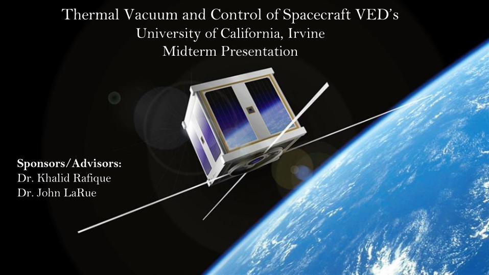
Thermal Vacuum and Control of Spacecraft VED’sUniversity of California, Irvine
Midterm Presentation
Sponsors/Advisors:
Dr. Khalid Rafique
Dr. John LaRue
Introduction
Thermal Vacuum and Control of Spacecraft VED's
Background | Capstone Project
❑ Background▪ Spacecraft Thermal Management System (STMS) is senior design project tasked to design and
assemble a variable emissivity device/surface (VED) as a prototype to design a thermal radiator for
deep space mission i.e. no environmental thermal flux data is available. VED will self-regulate. It is an
interdisciplinary project with students from MAE, Chem Engr and Mat Sci Depts., and Physical
Sciences Dept.
❑ Capstone Project - Objectives▪ Focused on designing a thermal vacuum chamber to allow:
o Thermal conduction and thermal radiation generation, detection, and testing capabilities within moderate to
high-vacuum regime
▪ Design a thermal control system capable of:o Thermal flux detection and data extraction under both standard atmosphere and moderate to high-vacuum
conditions
o Will integrate thermal control system into the chamber to perform validation testing for:
• Electrophoretic Display (EPD)
• Smart Window Technology
• NiO/WO3 thin-films, connected via gel-electrolyte → “electrochromic cell”.
Thermal Vacuum and Control of Spacecraft VED's Brandon Grajeda 1
Vacuum Chamber Design
Thermal Vacuum and Control of Spacecraft VED's 2
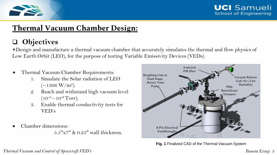
Thermal Vacuum Chamber Design:
Thermal Vacuum and Control of Spacecraft VED's
❑ Objectives■Design and manufacture a thermal vacuum chamber that accurately simulates the thermal and flow physics of
Low Earth Orbit (LEO), for the purpose of testing Variable Emissivity Devices (VEDs).
Fig. 1 Finalized CAD of the Thermal Vacuum System
Roughing Line to Dual-Stage,Rotary Vane
Pump
4-micron PM filter
Vacuum Release(Lab-Air | Low
Humidity)
8-Pin Electrical Feedthroughs
7056-Borosilicate
Viewport
Basem Eraqi 3
■ Thermal Vacuum Chamber Requirements:
1. Simulate the Solar radiation of LEO
(~1366 W/m2).
2. Reach and withstand high vacuum level
(10-3 – 10-9 Torr).
3. Enable thermal conductivity tests for
VED’s
■ Chamber dimensions:
5.5"x7" & 0.25" wall thickness.
Thermal Vacuum Chamber Design:
Thermal Vacuum and Control of Spacecraft VED's
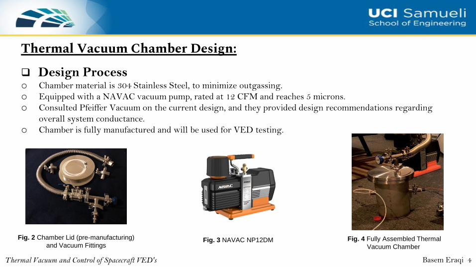
❑ Design Processo Chamber material is 304 Stainless Steel, to minimize outgassing.
o Equipped with a NAVAC vacuum pump, rated at 12 CFM and reaches 5 microns.
o Consulted Pfeiffer Vacuum on the current design, and they provided design recommendations regarding
overall system conductance.
o Chamber is fully manufactured and will be used for VED testing.
Fig. 2 Chamber Lid (pre-manufacturing)
and Vacuum FittingsFig. 4 Fully Assembled Thermal
Vacuum ChamberFig. 3 NAVAC NP12DM
Basem Eraqi 4
Thermal Vacuum "at home" Testing
Thermal Vacuum and Control of Spacecraft VED's Basem Eraqi 5
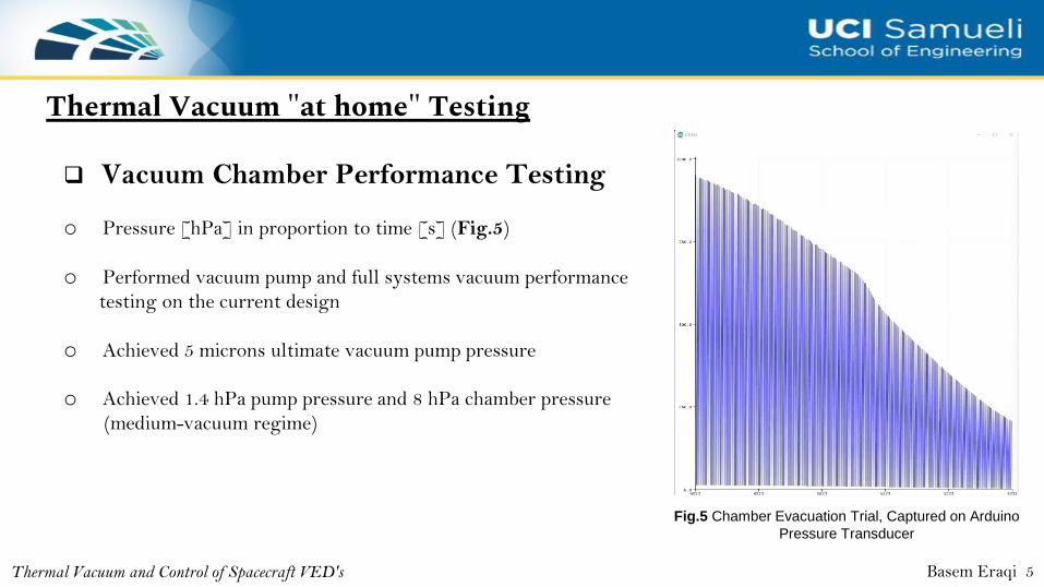
Fig.5 Chamber Evacuation Trial, Captured on Arduino
Pressure Transducer
❑ Vacuum Chamber Performance Testing
o Pressure [hPa] in proportion to time [s] (Fig.5)
o Performed vacuum pump and full systems vacuum performance
testing on the current design
o Achieved 5 microns ultimate vacuum pump pressure
o Achieved 1.4 hPa pump pressure and 8 hPa chamber pressure
(medium-vacuum regime)
Thermal Vacuum "at home" Testing
Thermal Vacuum and Control of Spacecraft VED's
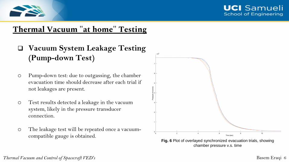
❑ Vacuum System Leakage Testing
(Pump-down Test)
o Pump-down test: due to outgassing, the chamber
evacuation time should decrease after each trial if
not leakages are present.
o Test results detected a leakage in the vacuum
system, likely in the pressure transducer
connection.
o The leakage test will be repeated once a vacuum-
compatible gauge is obtained.
Basem Eraqi 6
Fig. 6 Plot of overlayed synchronized evacuation trials, showing
chamber pressure v.s. time
Solar Emittance Device (SED)
Thermal Vacuum and Control of Spacecraft VED's 7
Thermal Vacuum and Control of Spacecraft VED's
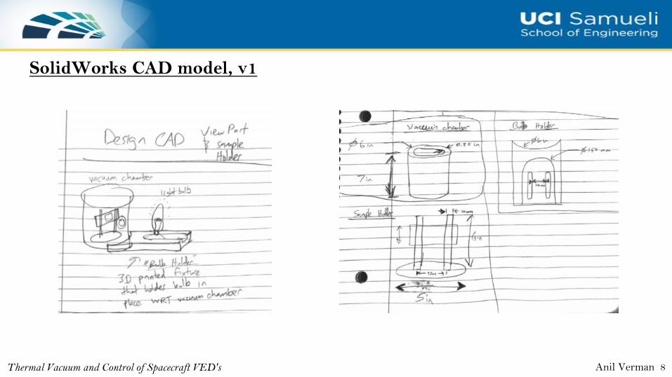
SolidWorks CAD model, v1
Anil Verman 8
SolidWorks CAD model, v1
Thermal Vacuum and Control of Spacecraft VED's
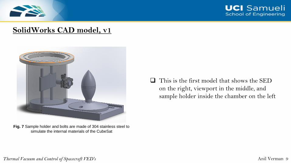
Fig. 7 Sample holder and bolts are made of 304 stainless steel to
simulate the internal materials of the CubeSat
❑ This is the first model that shows the SED
on the right, viewport in the middle, and
sample holder inside the chamber on the left
Anil Verman 9
ANSYS Simulation
Thermal Vacuum and Control of Spacecraft VED's
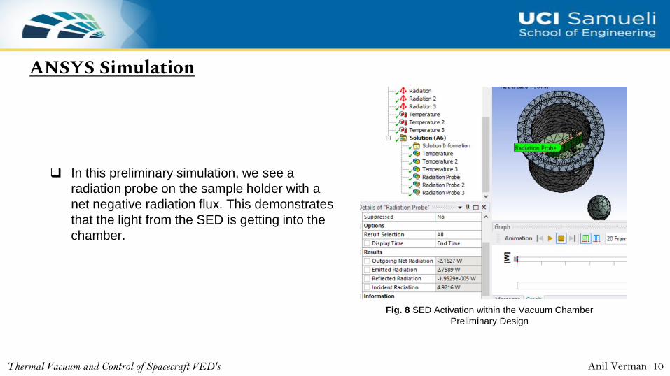
❑ In this preliminary simulation, we see a
radiation probe on the sample holder with a
net negative radiation flux. This demonstrates
that the light from the SED is getting into the
chamber.
Anil Verman 10
Fig. 8 SED Activation within the Vacuum Chamber
Preliminary Design
Redesign of CAD
Thermal Vacuum and Control of Spacecraft VED's
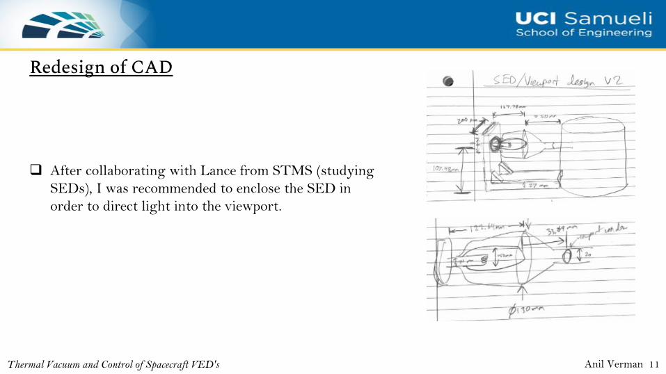
❑ After collaborating with Lance from STMS (studying
SEDs), I was recommended to enclose the SED in
order to direct light into the viewport.
Anil Verman 11
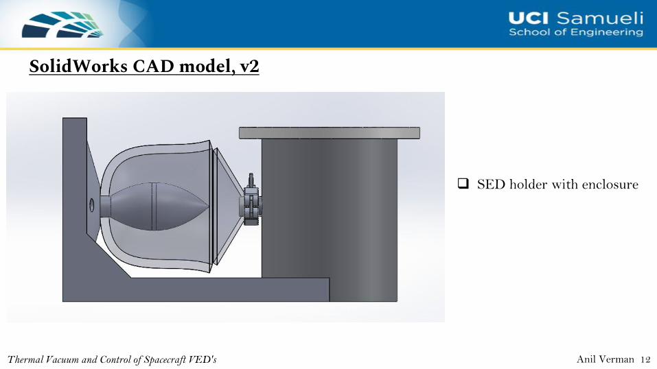
SolidWorks CAD model, v2
Thermal Vacuum and Control of Spacecraft VED's
❑ SED holder with enclosure
Anil Verman 12
Electrophoretic Display (EPD)and Smart Window Technology
Thermal Vacuum and Control of Spacecraft VED's 13
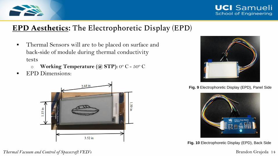
EPD Aesthetics: The Electrophoretic Display (EPD)
Fig. 9 Electrophoretic Display (EPD), Panel Side
Fig. 10 Electrophoretic Display (EPD), Back Side
▪ Thermal Sensors will are to be placed on surface and
back-side of module during thermal conductivity
testso Working Temperature (@ STP): 0o C - 50o C
▪ EPD Dimensions:
Brandon Grajeda 14Thermal Vacuum and Control of Spacecraft VED's
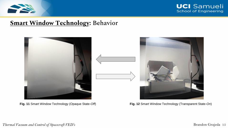
Smart Window Technology: Behavior
Fig. 11 Smart Window Technology (Opaque State-Off) Fig. 12 Smart Window Technology (Transparent State-On)
Brandon Grajeda 15Thermal Vacuum and Control of Spacecraft VED's
Heat Transfer Analysis
Thermal Vacuum and Control of Spacecraft VED's 16
Thermal Vacuum and Control of Spacecraft VED's
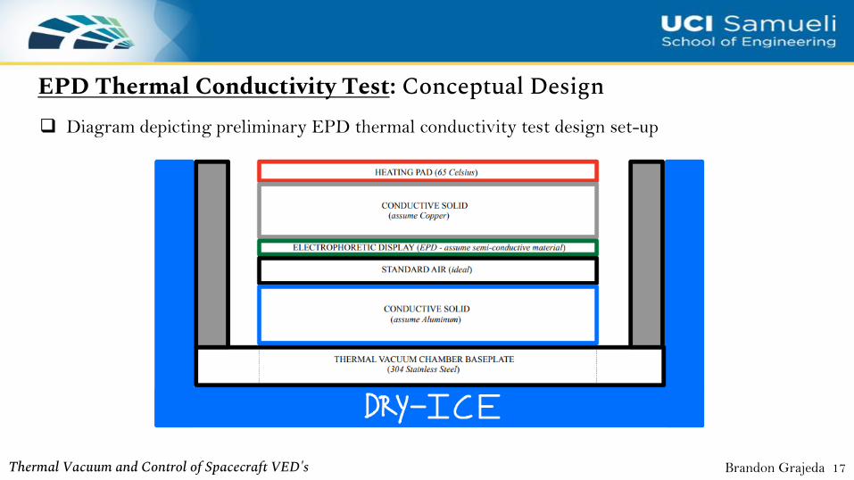
❑ Diagram depicting preliminary EPD thermal conductivity test design set-up
Brandon Grajeda 17
EPD Thermal Conductivity Test: Conceptual Design
Thermal Vacuum and Control of Spacecraft VED's
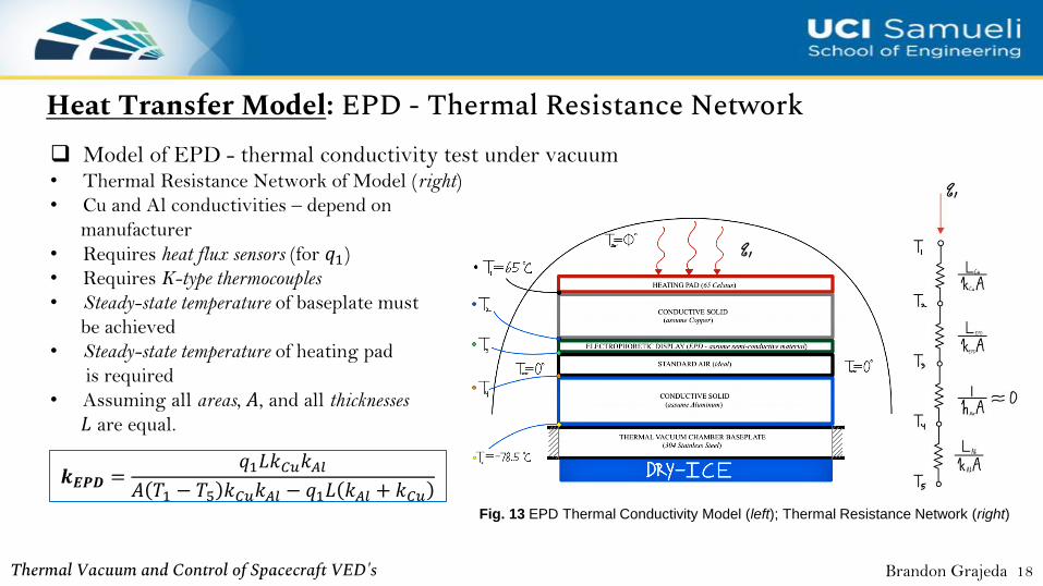
❑ Model of EPD - thermal conductivity test under vacuum• Thermal Resistance Network of Model (right)
• Cu and Al conductivities – depend on
manufacturer
• Requires heat flux sensors (for 𝑞1)
• Requires K-type thermocouples
• Steady-state temperature of baseplate must
be achieved
• Steady-state temperature of heating pad
is required
• Assuming all areas, 𝐴, and all thicknesses
𝐿 are equal.
Brandon Grajeda 18
𝒌𝑬𝑷𝑫 =𝑞1𝐿𝑘𝐶𝑢𝑘𝐴𝑙
𝐴 𝑇1 − 𝑇5 𝑘𝐶𝑢𝑘𝐴𝑙 − 𝑞1𝐿 𝑘𝐴𝑙 + 𝑘𝐶𝑢
Heat Transfer Model: EPD - Thermal Resistance Network
Fig. 13 EPD Thermal Conductivity Model (left); Thermal Resistance Network (right)
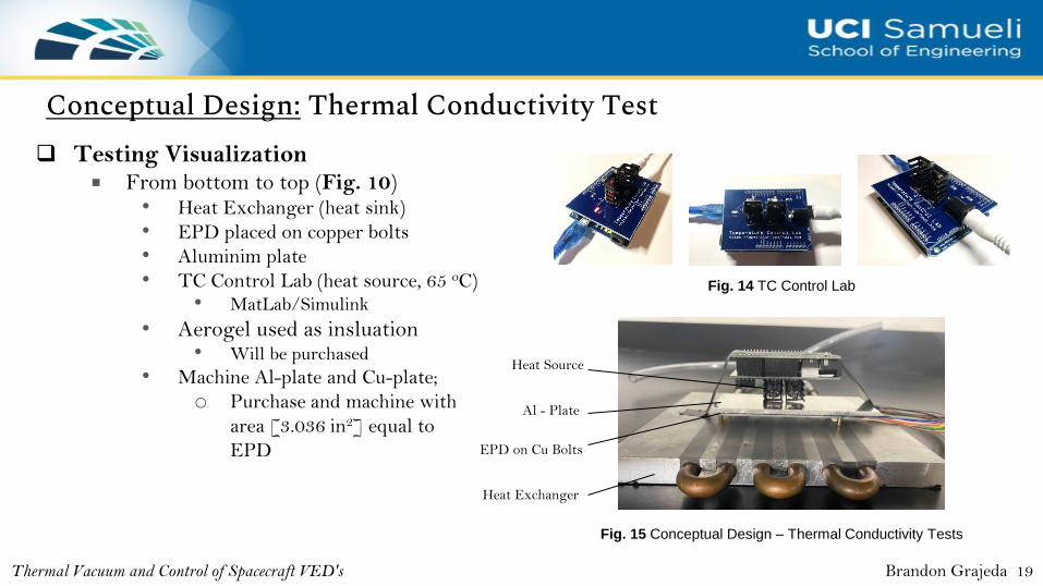
Conceptual Design: Thermal Conductivity Test
Thermal Vacuum and Control of Spacecraft VED's
Fig. 14 TC Control Lab
❑ Testing Visualization■ From bottom to top (Fig. 10)
• Heat Exchanger (heat sink)
• EPD placed on copper bolts
• Aluminim plate
• TC Control Lab (heat source, 65 oC)• MatLab/Simulink
• Aerogel used as insluation• Will be purchased
• Machine Al-plate and Cu-plate;
o Purchase and machine with
area [3.036 in2] equal to
EPD
Fig. 15 Conceptual Design – Thermal Conductivity Tests
Brandon Grajeda 19
Heat Source
Al - Plate
EPD on Cu Bolts
Heat Exchanger
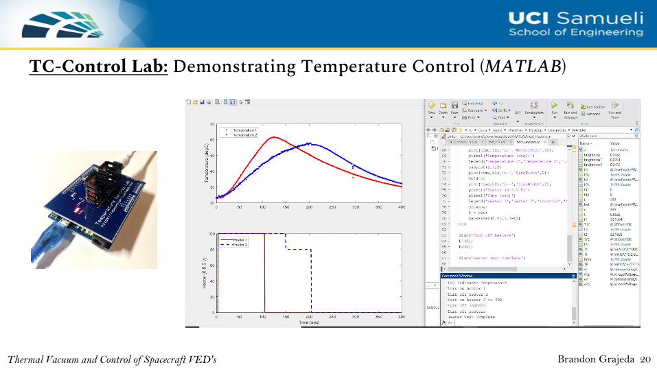
Thermal Vacuum and Control of Spacecraft VED's Brandon Grajeda 20
TC-Control Lab: Demonstrating Temperature Control (MATLAB)
EPD - Reflectance and Transmissivity
Thermal Vacuum and Control of Spacecraft VED's 21
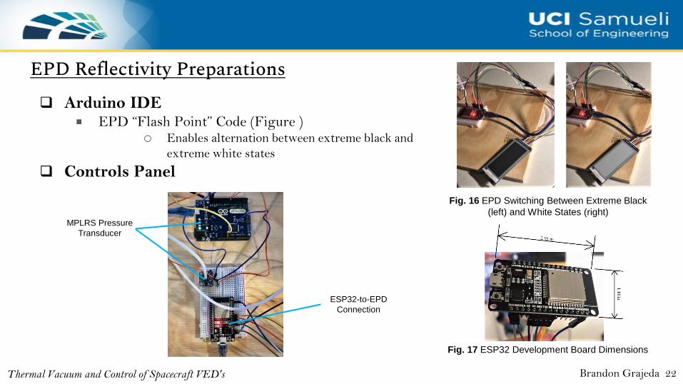
EPD Reflectivity Preparations
Thermal Vacuum and Control of Spacecraft VED's
Fig. 16 EPD Switching Between Extreme Black
(left) and White States (right)
❑ Arduino IDE■ EPD “Flash Point” Code (Figure )
o Enables alternation between extreme black and
extreme white states
❑ Controls Panel
Fig. 17 ESP32 Development Board Dimensions
Brandon Grajeda 22
MPLRS Pressure
Transducer
ESP32-to-EPD
Connection
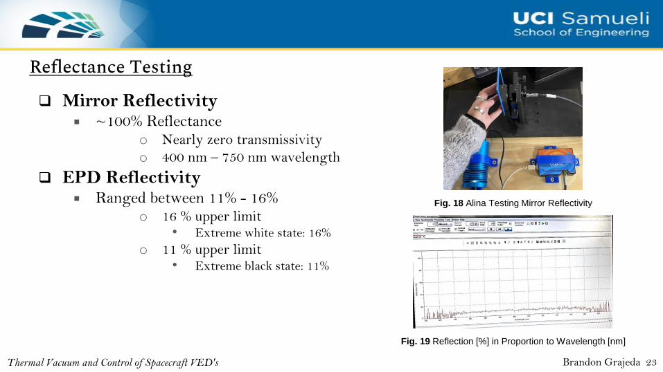
Reflectance Testing
Thermal Vacuum and Control of Spacecraft VED's
Fig. 18 Alina Testing Mirror Reflectivity
❑ Mirror Reflectivity■ ~100% Reflectance
o Nearly zero transmissivity
o 400 nm – 750 nm wavelength
❑ EPD Reflectivity■ Ranged between 11% - 16%
o 16 % upper limit• Extreme white state: 16%
o 11 % upper limit• Extreme black state: 11%
Fig. 19 Reflection [%] in Proportion to Wavelength [nm]
Brandon Grajeda 23
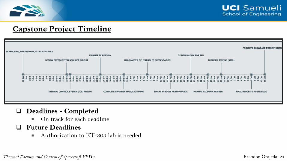
Capstone Project Timeline
Thermal Vacuum and Control of Spacecraft VED's
❑ Deadlines - Completed■ On track for each deadline
❑ Future Deadlines■ Authorization to ET-303 lab is needed
Brandon Grajeda 24
Further Information/References
➢ Project Website
• [1] Daniel M Hatzung. Thermal Characterization of the Air Force Institute of Technology Solar
Simulation Thermal Vacuum Chamber. Tech. rep. AIR FORCE INSTITUTE OFTECHNOLOGY
WRIGHT-PATTERSON AFB OH GRADUATE SCHOOL OF . . .,2014.
• [2] Dongliang Zhao, Xin Qian, Xiaokun Gu, et al. “Measurement techniques for thermal
conductivity and interfacial thermal conductance of bulk and thin film materials”. In: Journal of
Electronic Packaging 138.4 (2016).
Thermal Vacuum and Control of Spacecraft VED's 25