Embed Size (px)
Citation preview
TFAWS 2004
Mechanically Pumped Fluid Loops for Spacecraft Thermal Control:
Past, Present & FuturePast, Present & Future
Pradeep BhandariGajanana C. Birur, Gani Ganapathi, Anthony D. Paris
Mike Pauken, Keith Novak, Glenn Tsuyuki
Jet Propulsion LaboratoryCalifornia Institute of Technology
September 3, 200415th Annual Thermal & Fluid Analysis Workshop
Pasadena, CA
TFAWS 2004
2Pradeep Bhandari
Outline
• Fundamental Requirements for Thermal Control of Robotic Spacecraft & Instruments
• Traditional Methods for Thermal Control of Spacecraft• What is a Mechanically Pumped Fluid Loop?• Why Use a Pumped Fluid Loop for Thermal Control?• Fundamental Physics of Pumped Fluid Loops• Basic Architecture• History• Working Fluids• Characteristics of Pumped Loop Components• Leaks, Leaks, Leaks• Compatibility of Fluids and Wetted Materials• Development Tests• Other Considerations
TFAWS 2004
3Pradeep Bhandari
Outline
• Case Study: Mars Pathfinder, MPF (PastPast)• Mars Exploration Rover, MER (PresentPresent)• Mars Science Laboratory, MSL (FutureFuture)• Next Generation Loops• Summary
TFAWS 2004
4Pradeep Bhandari
Fundamental Requirements for Thermal Control of Spacecraft
• Primary Goal: Maintain temperatures of all components within their allowable limits with minimal complexity, maximum reliability and minimal use of resources like electrical power and mass
• All components are thermally connected to space via the internals of the spacecraft
• If one is trying to reject heat:– Pick up heat from heat sources and eventually reject it to space via
radiation· Radiation to space is the only heat loss mechanism due to lack of an atmosphere
• If one is trying to conserve heat:– Insulate the heat sources from the heat sink (use insulation)
• If one is trying to supply heat:– Pick up heat from heat sources and eventually insert it to the component
• The designing and controlling of this connection to achieve temperature levels within each component that satisfy their allowable limits is one of the most important aspects of thermal control of spacecraft
TFAWS 2004
5Pradeep Bhandari
Fundamental Requirements for Thermal Control of Spacecraft
• Typical Allowable Flight Temperatures
– Electronics: -40/50C– Battery: -20/30C– Actuators: -55/25C (Operating)
-105/40C (non-operating)– Propulsion Tanks: 15/30C– Propulsion lines: 15/50C– Thruster Valve: 20/110C (operate), 20/50C (non-operate)
TFAWS 2004
6Pradeep Bhandari
Traditional Methods for Thermal Control of Spacecraft
• Typical thermal control methods rely on a passive connection between innards of the spacecraft and space
• Passive couplings could be conductive or radiative– Examples of conductive coupling:
· S/C metallic structure from electronics to radiator– Examples of radiative coupling:
· High emissivity thermal control paints, tapes• Passive isolations could be conductive or radiative
– Examples of conductive isolation:· Non-metallic structure (fiberglass isolators) from electronics to radiator
– Examples of radiative isolation:· Low emissivity thermal control paints, tapes, Multi-Layer insulation (MLI)
• Louvers are radiative means to achieve variable emissivity passively– Very sensitive to solar exposure and heavy
• Heat pipes are “semi-passive’ means to connect components to space– Use liquid-vapor phase change to transport heat– Superior to ordinary conductors– Can be used to condcut or isolate (Variable conductance heat pipe)– Very sensitive to gravity and tilt
· Very hard to test in 1-g for complex 3-D geometries
TFAWS 2004
7Pradeep Bhandari
Traditional Methods for Thermal Control of Spacecraft
• Active means of achieving variable connections– Heat Switches
· Heavy and low heat flow capacity
• Active means of supplying/removing heat for T/C– Heaters– Thermostats– Thermoelectric coolers
TFAWS 2004
8Pradeep Bhandari
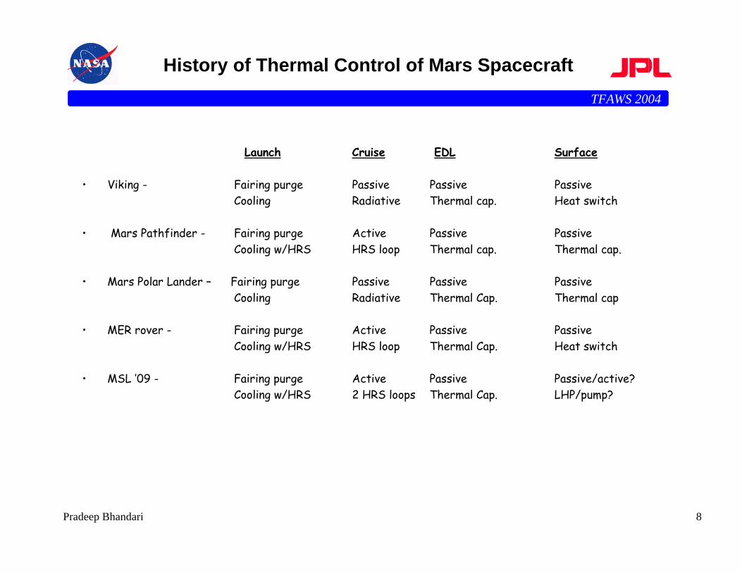
History of Thermal Control of Mars Spacecraft
Launch Cruise EDL Surface
• Viking - Fairing purge Passive Passive Passive Cooling Radiative Thermal cap. Heat switch
• Mars Pathfinder - Fairing purge Active Passive PassiveCooling w/HRS HRS loop Thermal cap. Thermal cap.
• Mars Polar Lander – Fairing purge Passive Passive PassiveCooling Radiative Thermal Cap. Thermal cap
• MER rover - Fairing purge Active Passive PassiveCooling w/HRS HRS loop Thermal Cap. Heat switch
• MSL ’09 - Fairing purge Active Passive Passive/active?Cooling w/HRS 2 HRS loops Thermal Cap. LHP/pump?
TFAWS 2004
9Pradeep Bhandari
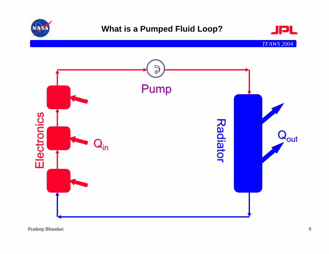
What is a Pumped Fluid Loop?E
lect
roni
csE
lect
roni
cs Radiator
Radiator
PumpPump
QQininQQoutout
TFAWS 2004
10Pradeep Bhandari
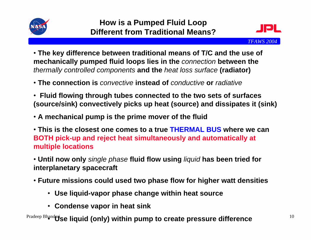
How is a Pumped Fluid Loop Different from Traditional Means?
• The key difference between traditional means of T/C and the use of mechanically pumped fluid loops lies in the connection between the thermally controlled components and the heat loss surface (radiator)
• The connection is convective instead of conductive or radiative
• Fluid flowing through tubes connected to the two sets of surfaces (source/sink) convectively picks up heat (source) and dissipates it (sink)
• A mechanical pump is the prime mover of the fluid
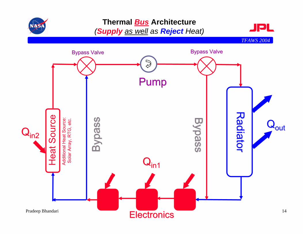
• This is the closest one comes to a true THERMAL BUS where we can BOTH pick-up and reject heat simultaneously and automatically at multiple locations
• Until now only single phase fluid flow using liquid has been tried for interplanetary spacecraft
• Future missions could used two phase flow for higher watt densities
• Use liquid-vapor phase change within heat source
• Condense vapor in heat sink
• Use liquid (only) within pump to create pressure difference
TFAWS 2004
11Pradeep Bhandari
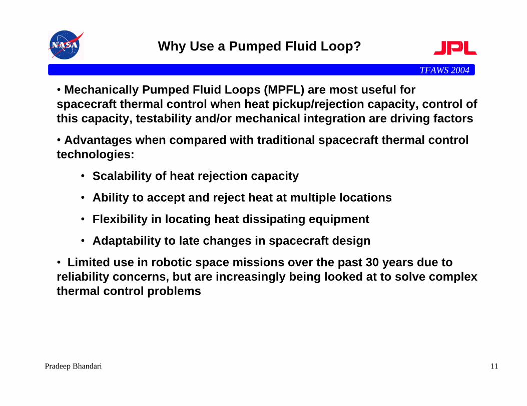
Why Use a Pumped Fluid Loop?
• Mechanically Pumped Fluid Loops (MPFL) are most useful for spacecraft thermal control when heat pickup/rejection capacity, control of this capacity, testability and/or mechanical integration are driving factors
• Advantages when compared with traditional spacecraft thermal control technologies:
• Scalability of heat rejection capacity
• Ability to accept and reject heat at multiple locations
• Flexibility in locating heat dissipating equipment
• Adaptability to late changes in spacecraft design
• Limited use in robotic space missions over the past 30 years due to reliability concerns, but are increasingly being looked at to solve complex thermal control problems
TFAWS 2004
12Pradeep Bhandari
Pros of Pumped Fluid Loop
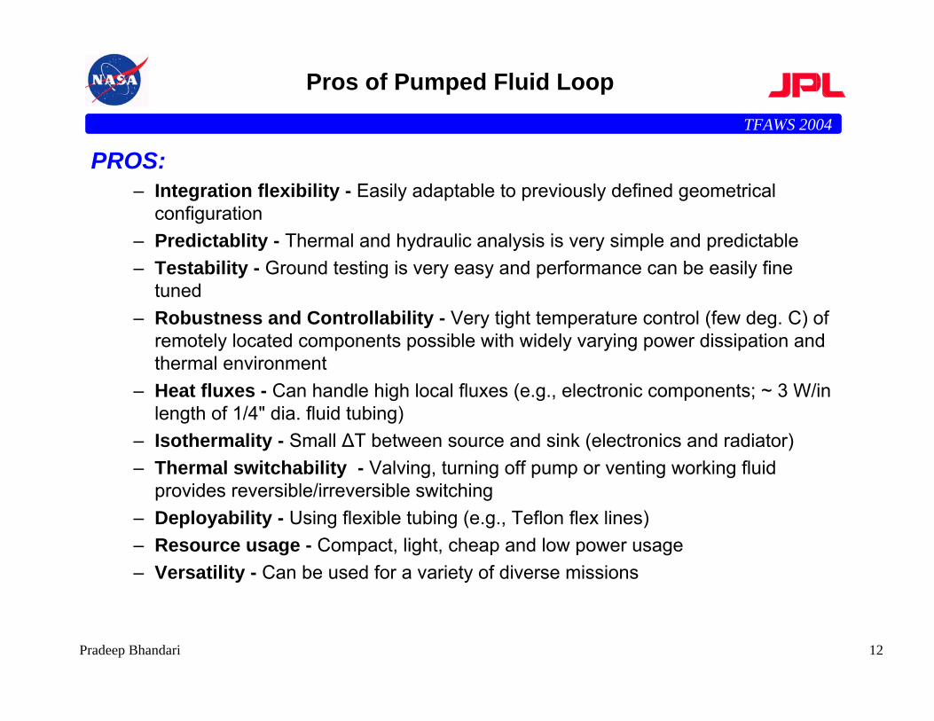
PROS:– Integration flexibility - Easily adaptable to previously defined geometrical
configuration– Predictablity - Thermal and hydraulic analysis is very simple and predictable– Testability - Ground testing is very easy and performance can be easily fine
tuned– Robustness and Controllability - Very tight temperature control (few deg. C) of
remotely located components possible with widely varying power dissipation and thermal environment
– Heat fluxes - Can handle high local fluxes (e.g., electronic components; ~ 3 W/in length of 1/4" dia. fluid tubing)
– Isothermality - Small ∆T between source and sink (electronics and radiator)– Thermal switchability - Valving, turning off pump or venting working fluid
provides reversible/irreversible switching– Deployability - Using flexible tubing (e.g., Teflon flex lines)– Resource usage - Compact, light, cheap and low power usage– Versatility - Can be used for a variety of diverse missions
TFAWS 2004
13Pradeep Bhandari
Cons of Pumped Fluid Loop?
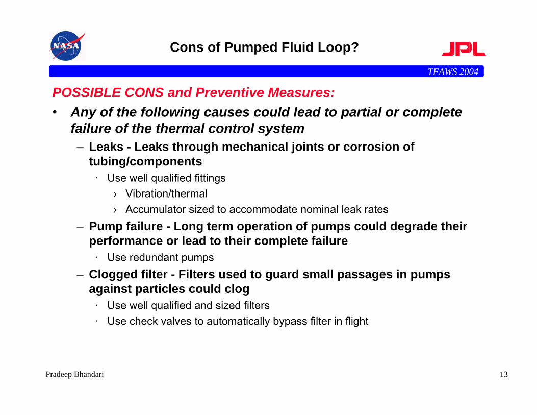
POSSIBLE CONS and Preventive Measures:• Any of the following causes could lead to partial or complete
failure of the thermal control system– Leaks - Leaks through mechanical joints or corrosion of
tubing/components· Use well qualified fittings
› Vibration/thermal› Accumulator sized to accommodate nominal leak rates
– Pump failure - Long term operation of pumps could degrade their performance or lead to their complete failure
· Use redundant pumps– Clogged filter - Filters used to guard small passages in pumps
against particles could clog· Use well qualified and sized filters· Use check valves to automatically bypass filter in flight
TFAWS 2004
14Pradeep Bhandari
Thermal Bus Architecture(Supply as well as Reject Heat)
PumpPump
Radiator
Radiator
QQoutoutQQin2in2
Byp
ass
Byp
ass B
ypassB
ypass
ElectronicsElectronics
QQin1in1Hea
t Sou
rce
Add
ition
al H
eat S
ourc
e:S
olar
Arra
y, R
TG, e
tc.
Bypass ValveBypass Valve Bypass ValveBypass Valve
TFAWS 2004
15Pradeep Bhandari
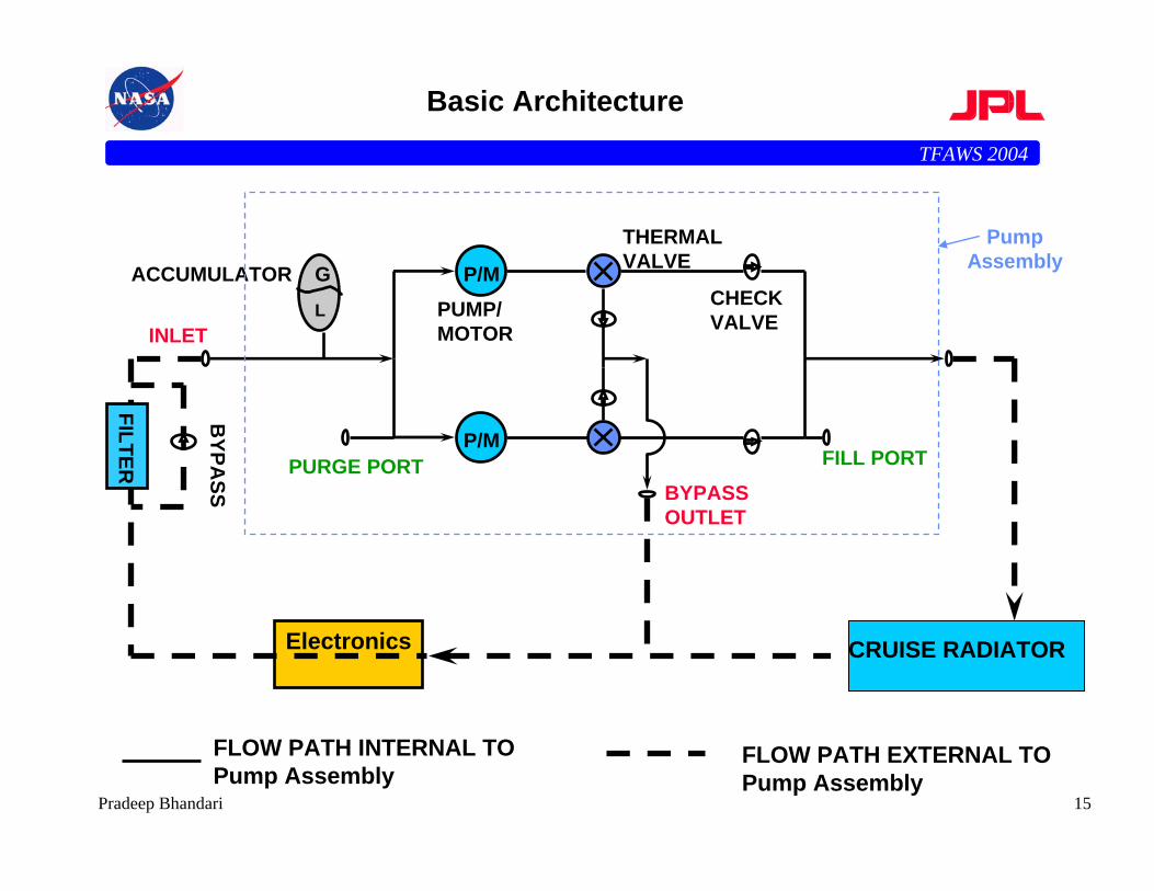
Basic Architecture
P/M
P/M
CHECK VALVEINLET
FILL PORTPURGE PORT
ACCUMULATORPUMP/MOTOR
THERMALVALVE
BYPASS OUTLET
CRUISE RADIATORElectronics
FILTER
BYPA
SS
GL
FLOW PATH EXTERNAL TOPump Assembly
FLOW PATH INTERNAL TOPump Assembly
Pump Assembly
TFAWS 2004
16Pradeep Bhandari
Fundamental Physics of a Pumped Fluid Loop
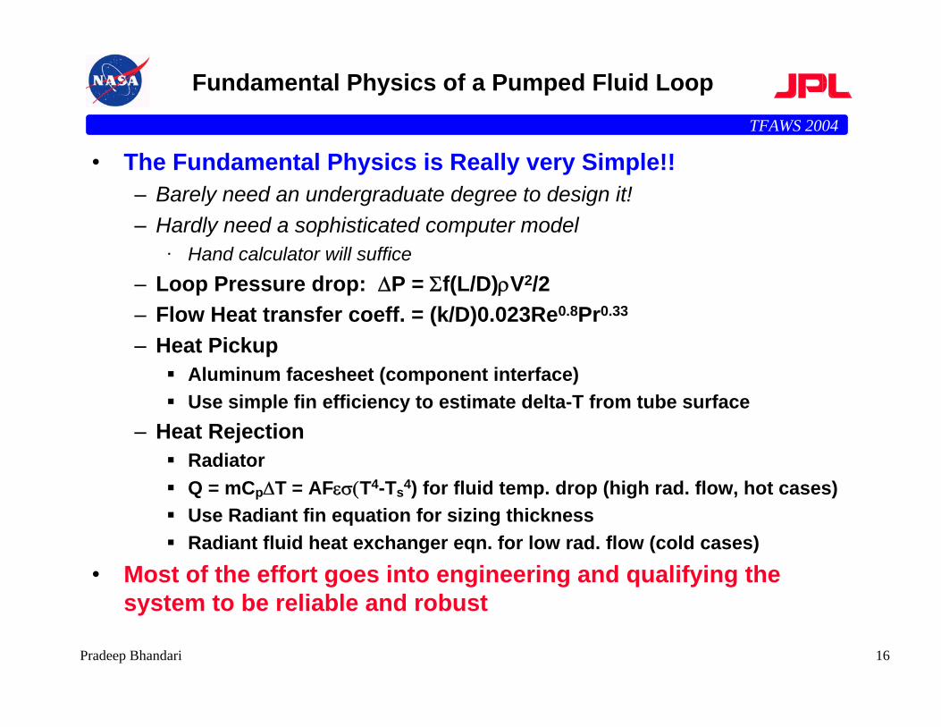
• The Fundamental Physics is Really very Simple!!– Barely need an undergraduate degree to design it!– Hardly need a sophisticated computer model
· Hand calculator will suffice– Loop Pressure drop: ∆P = Σf(L/D)ρV2/2– Flow Heat transfer coeff. = (k/D)0.023Re0.8Pr0.33
– Heat PickupAluminum facesheet (component interface)Use simple fin efficiency to estimate delta-T from tube surface
– Heat RejectionRadiatorQ = mCp∆T = AFεσ(T4-Ts4) for fluid temp. drop (high rad. flow, hot cases)Use Radiant fin equation for sizing thicknessRadiant fluid heat exchanger eqn. for low rad. flow (cold cases)
• Most of the effort goes into engineering and qualifying the system to be reliable and robust
TFAWS 2004
17Pradeep Bhandari
History of Mechanically Pumped Fluid Loops
• Mars Pathfinder (JPL, 1996) was the 1st Interplanetary Spacecraft to use a mechanically pumped cooling loop for thermal control during cruise
• Mars Exploration Rover (JPL, 2004) used a similar design adapted to its configuration, also during cruise
• Mars Science Laboratory (JPL, 2009) has base-lined twomechanical loops for thermal control– During cruise to cool the Radioisotope Thermo-Electric Generator
(RTG) which generates 2000 Watts of heat– For thermal control of the rover
· For both heating and cooling· Harvests up waste heat from the RTG for cold conditions· Uses radiators to maintain rovers temperatures during hot conditions
– 1st instance of using pumped fluid loop as a Thermal Bus to supplyas well as pick-up heat from electronics
TFAWS 2004
18Pradeep Bhandari
Mechanically Pumped Fluid Loop for Robotic Missions
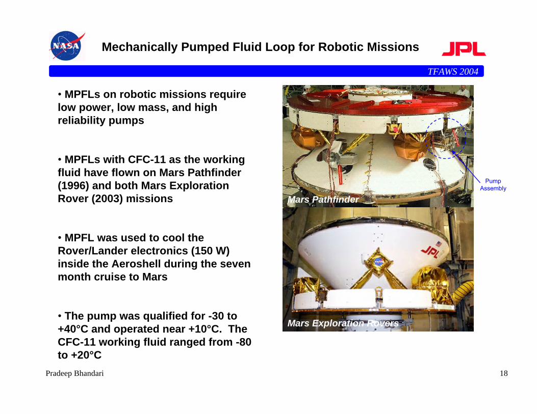
• MPFLs on robotic missions require low power, low mass, and high reliability pumps
• MPFLs with CFC-11 as the working fluid have flown on Mars Pathfinder (1996) and both Mars Exploration Rover (2003) missions
• MPFL was used to cool the Rover/Lander electronics (150 W) inside the Aeroshell during the seven month cruise to Mars
• The pump was qualified for -30 to +40°C and operated near +10°C. The CFC-11 working fluid ranged from -80 to +20°C
Mars Pathfinder
Mars Exploration Rovers
Pump Assembly
TFAWS 2004
19Pradeep Bhandari
Mechanically Pumped Fluid Loops on NASA Missions
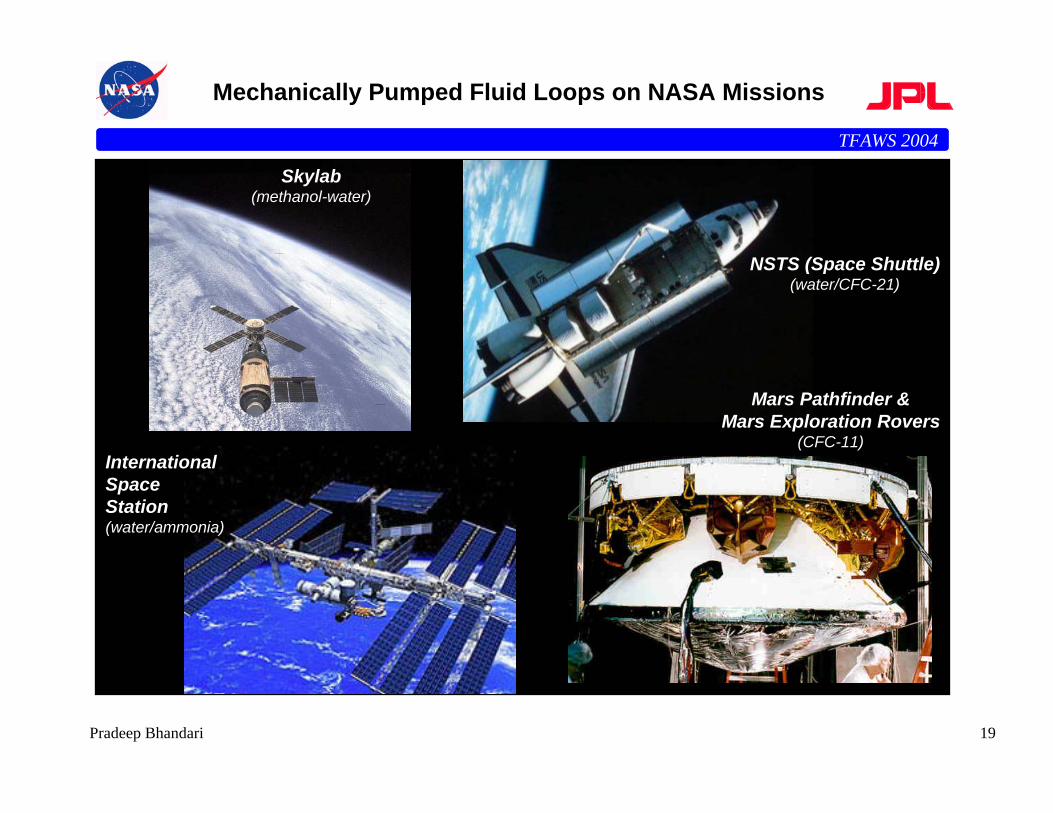
NSTS (Space Shuttle)(water/CFC-21)
Skylab(methanol-water)
Mars Pathfinder &Mars Exploration Rovers
(CFC-11)InternationalSpaceStation(water/ammonia)
TFAWS 2004
20Pradeep Bhandari
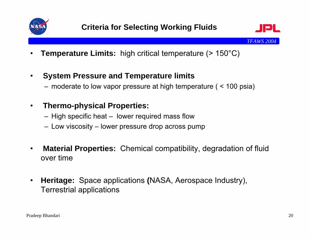
Criteria for Selecting Working Fluids
• Temperature Limits: high critical temperature (> 150°C)
• System Pressure and Temperature limits– moderate to low vapor pressure at high temperature ( < 100 psia)
• Thermo-physical Properties: – High specific heat – lower required mass flow – Low viscosity – lower pressure drop across pump
• Material Properties: Chemical compatibility, degradation of fluid over time
• Heritage: Space applications (NASA, Aerospace Industry), Terrestrial applications
TFAWS 2004
21Pradeep Bhandari
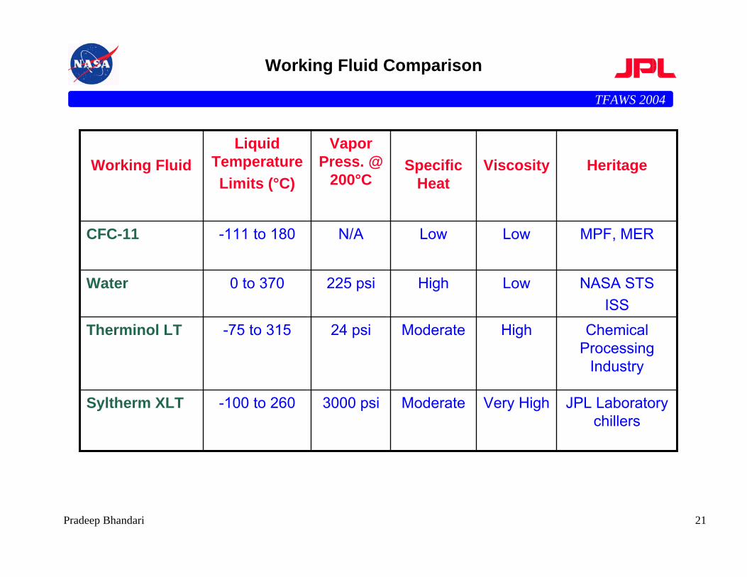
Working Fluid Comparison
Moderate
Moderate
High
Low
Specific Heat
JPL Laboratory chillers
Very High3000 psi-100 to 260Syltherm XLT
Chemical Processing
Industry
High24 psi-75 to 315Therminol LT
NASA STSISS
Low225 psi0 to 370Water
MPF, MERLowN/A-111 to 180 CFC-11
HeritageViscosityVapor
Press. @ 200°C
Liquid Temperature Limits (°C)
Working Fluid
TFAWS 2004
22Pradeep Bhandari
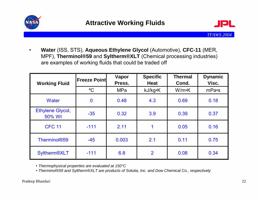
Attractive Working Fluids
Freeze Point Vapor Press.
Specific Heat
Thermal Cond.
Dynamic Visc.
ºC MPa kJ/kg•K W/m•K mPa•s
Water 0 0.48 4.3 0.69 0.18
Ethylene Glycol, 50% Wt -35 0.32 3.9 0.39 0.37
CFC 11 -111 2.11 1 0.05 0.16
Therminol®59 -45 0.003 2.1 0.11 0.75
Syltherm®XLT -111 6.8 2 0.08 0.34
Working Fluid
• Thermophysical properties are evaluated at 150°C• Therminol®59 and Syltherm®XLT are products of Solutia, Inc. and Dow Chemical Co., respectively
• Water (ISS, STS), Aqueous Ethylene Glycol (Automotive), CFC-11 (MER, MPF), Therminol®59 and Syltherm®XLT (Chemical processing industries) are examples of working fluids that could be traded off
TFAWS 2004
23Pradeep Bhandari
Typical Characteristics of Components in Pumped Loop
• Prevention of leaks is of paramount importance!!!– Entire system is hermetically sealed (welded) except for few mechanical
joints (10-20) for spacecraft integration• Pumps
– The prime mover of fluid– Typically centrifugal– Journal bearings, all welded construction– Redundant set used for reliability
• Filter– Protects pump bearings from particles– Typically uses a check valve in parallel to bypass filter if filter saturates
in flight• Radiator
– Rejects heat to space– Plate welded, glued or brazed to fluid tubing
TFAWS 2004
24Pradeep Bhandari
Typical Characteristics of Components in Pumped Loop
• Accumulator– Maintains nearly constant pressure in system throughout mission– Gas charged with bellows separating gas from fluid
• Check Valves– Isolate redundant pump from flow path– Bypass particle filter, if it gets saturated
• Tubing– Aluminum (for heat transfer)
· Used in heat transfer areas› Heat pickup and rejection
· Lighter– Stainless Steel (for transport of fluid)
· Non-heat transfer areas· Maximum compatibility with working fluids· Heavier
TFAWS 2004
25Pradeep Bhandari
Leaks, Leaks and Leaks
• Single most important part of the design of pumped fluid loop is the prevention of leaks!
– Leaks of sizes larger than accumulator is sized for would be catastrophic· Could lead to mission failure
• System is of a welded construction as much as possible• Mechanical joints used sparingly - only when integration requires them
– Keep number of mechanical joints less than 10 – 20• Size Accumulator to accommodate nominal leak rates• Use highest quality - leak wise - mechanical joints• Attractive Mechanical Joints
– Swagelock VCR– Omnisafe (Swagelock like design with no torque on joint)– Ring Seals (O-Rings on A-N)– A-N (B-Nuts)
• Take mechanical joints out of load paths– Provide stress relief bends in tubing near joints– Brace joints by splines
• Qualify, Qualify, Qualify– Thermal and Vibrational– Leak tests
TFAWS 2004
26Pradeep Bhandari
Compatibility of Fluids & Wetted Materials
• Long term compatibility of materials in wetted path paramount• Typically designed to last 1 to 3 years of more• Stainless steels (e.g., 316 L) are very attractive
– Extremely low moisture content in Freon-11 systems is very critical· Typically < 10 ppm desirable· 100 ppm (saturation) leads to extensive corrosion
• Aluminum is attractive from thermal and mass standpoint– But not as compatible as SS– Low moisture content is critical
• For water based fluid systems, ultra pure (DI) water very desirable– Some anti-corrosion additives would inhibit corrosion
· But would require trade-off with thermo-fluid properties
• Motor/Pump material list to be carefully examined to ensure extreme compatibility with working fluid
TFAWS 2004
27Pradeep Bhandari
Development Tests for Mars Pathfinder
• Thermal-Hydraulic– Simulate Electronic Shelf & Radiator To Validate Thermal And Hydraulic
Performance Models– Excellent Agreement, Conservative
• Leaks:– Simulate Thermal Cycling & Launch Flexing Of "A-N" Fittings ("B-Nuts") To
Investigate Leak Potential -- Leak Rates Very Low (< 10-4 scc/s He)– Measure Leak Rate Of Freon Through Teflon Flex Lines -- Small Leak Rate– Accumulator Size Adequate To Accommodate Measured Leak Rates
• Material Compatibility:– Freon Moisture Tests– All Materials In Contact With Freon Undergoing Long Term Compatibility Tests
With Varying Levels Of Moisture (Al, SS, VITON, etc.) – Extremely Important To Minimize Moisture To Prevent Corrosion; Elaborate
Safeguards Taken In Freon Storage & Loading Process
TFAWS 2004
28Pradeep Bhandari
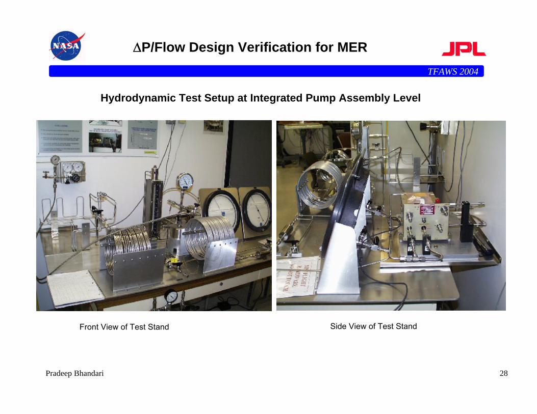
∆P/Flow Design Verification for MER
Front View of Test Stand Side View of Test Stand
Hydrodynamic Test Setup at Integrated Pump Assembly Level
TFAWS 2004
29Pradeep Bhandari
Life Tests on Mars Pathfinder
• Simulate Long Term Operation– ( 5000 Hours Flight Duration, 7 Months) Of Pump Assembly & Particle
Filter, In Conjunction With Rest Of HRS (Al, SS, Teflon Tubing, Accumulator, Etc.)
– 7300 Hours (10 Months) Of Uninterrupted Operation – No Pump Failures– Filter Used In Mock-up Had Inadequate Capacity & Was Bypassed (Flight
Filter At Least 5x Higher Capacity)· Flight Filter Uses Check Valve For Bypass
• Simulate & Measure Long Term Corrosion– On HRS Tubing (Al, SS)– Samples Of Tubing & Freon Liquid Taken Out Periodically For Analysis– No Evidence Of Corrosion Found
• Measure Long Term Leaks From HRS– Particularly Due To Mechanical Joints ("A-N" Fittings or "B-Nuts")– Relatively Large Leaks Observed In The Beginning Of Test Which Were
Corrected And Prompted A More Elaborate Leak Test Done Separately
TFAWS 2004
30Pradeep Bhandari
Other Considerations
• Venting– If fluid loop used in cruise but not for surface operations
(MER/MPF)– Venting of working fluid required prior to cruise stage separation– Controlled vent required to minimize torque and impulse (nutation)
on S/C– Pyro-actuated valve allows accumulator gas to push out liquid
though pyro-actuated valve to space· Nozzle axis lies on S/C c.g (MPF)
› Nutation exceeded estimates· Nozzle axis lies along S/C axis (MER)
› Nutation close to estimates› Desirable scheme
– Vent in a “bottle” could avoid torque/impulse by not venting to space
– Has not been implemented, but would be an attractive option· Particularly suited for fluid that could freeze up a nozzle (e.g., H2O, high
freezing point)
TFAWS 2004
31Pradeep Bhandari
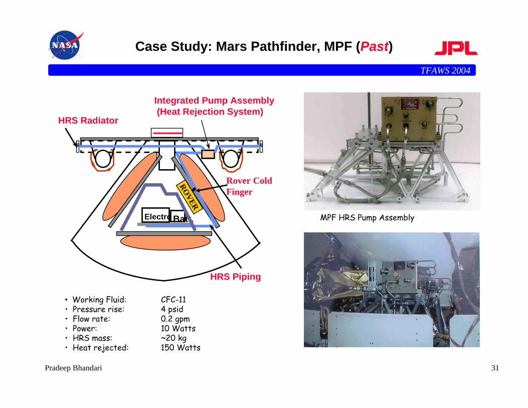
Case Study: Mars Pathfinder, MPF (Past)
• Working Fluid: CFC-11• Pressure rise: 4 psid• Flow rate: 0.2 gpm• Power: 10 Watts• HRS mass: ~20 kg• Heat rejected: 150 Watts
MPF HRS Pump Assembly
HRS Radiator
Integrated Pump Assembly(Heat Rejection System)
HRS Piping
ElectronicsBatt.
ROVER
Rover Cold Finger
TFAWS 2004
32Pradeep Bhandari
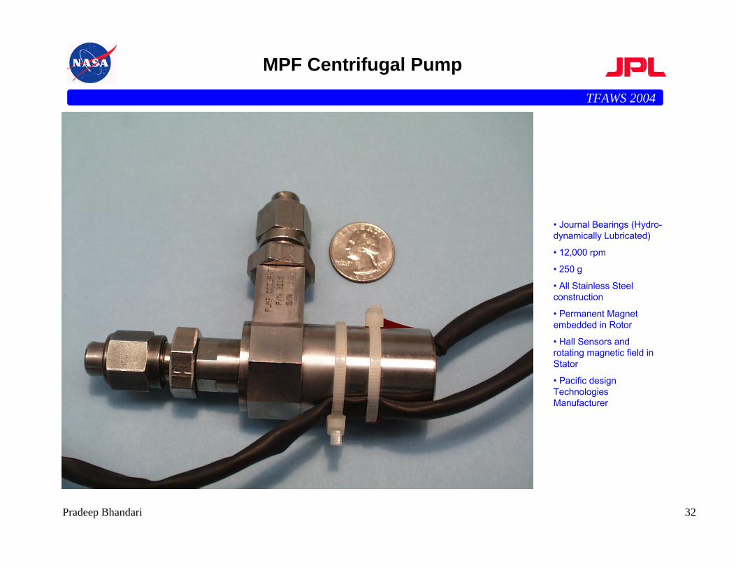
MPF Centrifugal Pump
• Journal Bearings (Hydro-dynamically Lubricated)
• 12,000 rpm
• 250 g
• All Stainless Steel construction
• Permanent Magnet embedded in Rotor
• Hall Sensors and rotating magnetic field in Stator
• Pacific design Technologies Manufacturer
TFAWS 2004
33Pradeep Bhandari
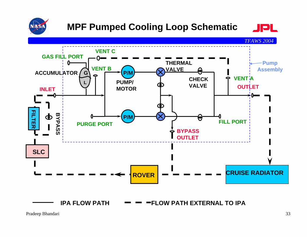
MPF Pumped Cooling Loop Schematic
P/M
P/M
CHECK VALVEINLET OUTLET
FILL PORTPURGE PORT
GAS FILL PORT
ACCUMULATORPUMP/MOTOR
THERMALVALVE
BYPASS OUTLET
CRUISE RADIATOR
SLC
ROVER
FILTER
BYPA
SS
GL
IPA FLOW PATH FLOW PATH EXTERNAL TO IPA
VENT B
VENT C
VENT A
Pump Assembly
TFAWS 2004
34Pradeep Bhandari
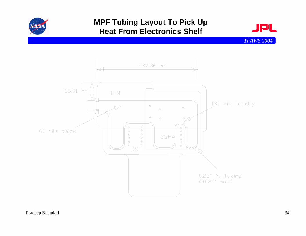
MPF Tubing Layout To Pick Up Heat From Electronics Shelf
TFAWS 2004
35Pradeep Bhandari
Case Study: Mars Pathfinder, MPF
• Pumped liquid (Freon-11) cooling system to maintain electronics temp. within insulated enclosure - 7 months mission
• 90 to 150 W cooling load• -60 to -20 oC (low); 5 to 70 oC (high) ... temp. limits of
components• 0.2 gpm flow; 4 psid pressure rise• 1/4” and 3/8” aluminum and SS tubing• tubing brazed to aluminum face-sheet on which electronics is
mounted• tubing strategically routed near high heat flux areas• 27’ x 8” x 0.030” aluminum radiator• white paint on both sides of radiator
– conductively decoupled from cruise stage– radiatively coupled to cruise stage (to prevent freon freezing during very cold
cases) - 93% of freon flow bypasses radiator in coldest cases
TFAWS 2004
36Pradeep Bhandari
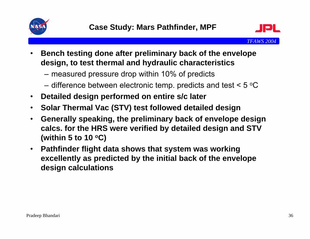
Case Study: Mars Pathfinder, MPF
• Bench testing done after preliminary back of the envelope design, to test thermal and hydraulic characteristics– measured pressure drop within 10% of predicts– difference between electronic temp. predicts and test < 5 oC
• Detailed design performed on entire s/c later• Solar Thermal Vac (STV) test followed detailed design• Generally speaking, the preliminary back of envelope design
calcs. for the HRS were verified by detailed design and STV (within 5 to 10 oC)
• Pathfinder flight data shows that system was working excellently as predicted by the initial back of the envelope design calculations
TFAWS 2004
37Pradeep Bhandari
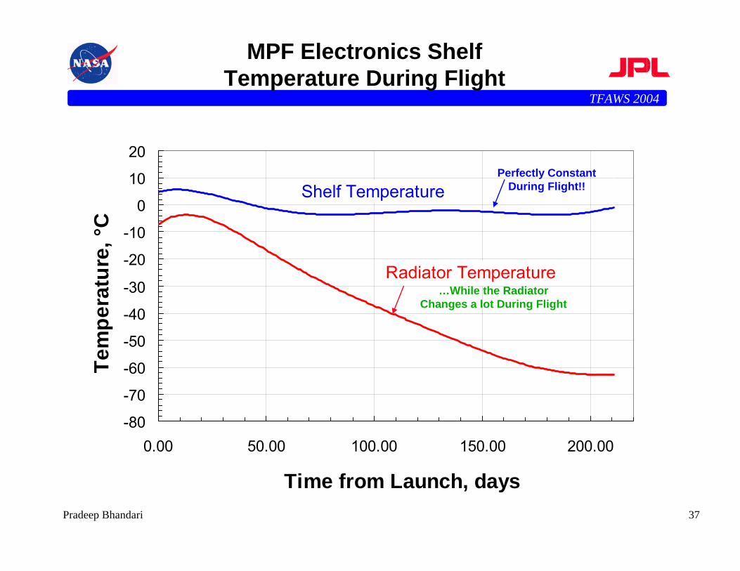
MPF Electronics Shelf Temperature During Flight
-80
-70
-60
-50
-40
-30
-20
-10
0
10
20
0.00 50.00 100.00 150.00 200.00
Time from Launch, days
Tem
pera
ture
, °C
Radiator Temperature
Shelf TemperaturePerfectly Constant
During Flight!!
…While the Radiator Changes a lot During Flight
TFAWS 2004
38Pradeep Bhandari
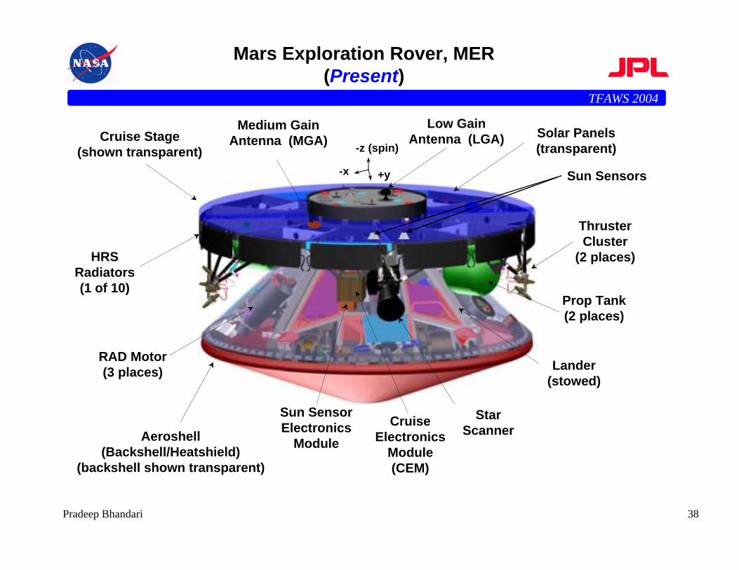
Mars Exploration Rover, MER (Present)
+y-x
-z (spin)
Sun Sensor Electronics
Module
Prop Tank(2 places)
Medium Gain Antenna (MGA)
Cruise Electronics
Module (CEM)
Solar Panels (transparent)
Low Gain Antenna (LGA) Cruise Stage
(shown transparent)
HRS Radiators (1 of 10)
Aeroshell(Backshell/Heatshield)
(backshell shown transparent)
Lander(stowed)
Star Scanner
RAD Motor (3 places)
Sun Sensors
Thruster Cluster
(2 places)
TFAWS 2004
39Pradeep Bhandari
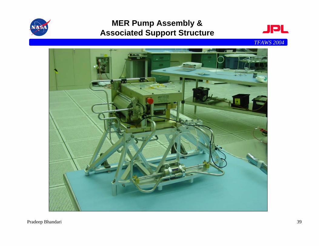
MER Pump Assembly & Associated Support Structure
TFAWS 2004
40Pradeep Bhandari
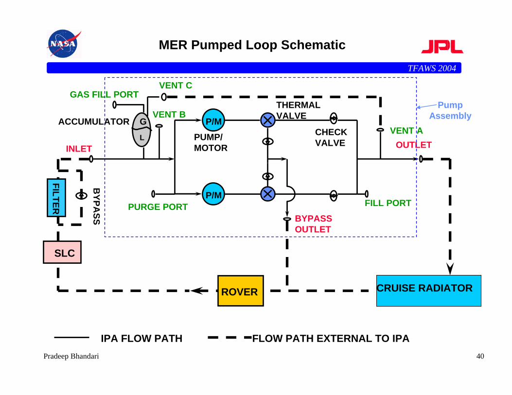
MER Pumped Loop Schematic
P/M
P/M
CHECK VALVEINLET OUTLET
FILL PORTPURGE PORT
GAS FILL PORT
ACCUMULATORPUMP/MOTOR
THERMALVALVE
BYPASS OUTLET
CRUISE RADIATOR
SLC
ROVER
FILTER
BYPA
SS
GL
IPA FLOW PATH FLOW PATH EXTERNAL TO IPA
VENT B
VENT C
VENT A
Pump Assembly
TFAWS 2004
41Pradeep Bhandari
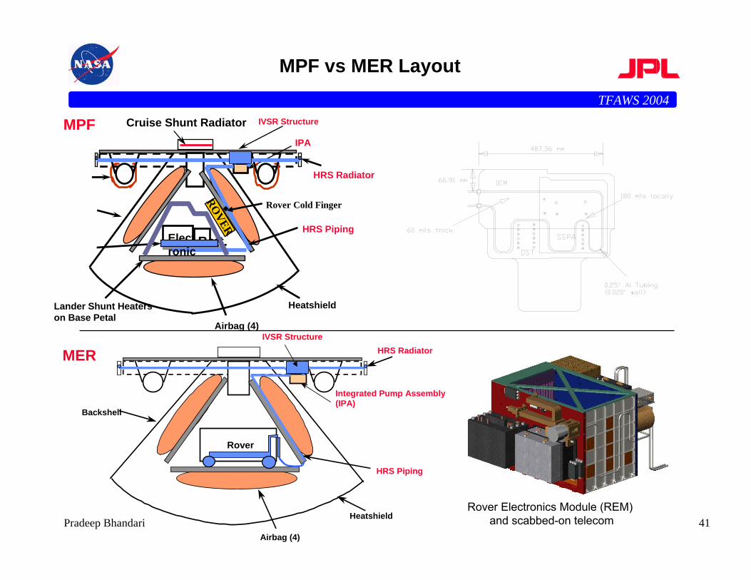
MPF vs MER Layout
MPF
HRS Radiator
Cruise Shunt Radiator
Lander Shunt Heaterson Base Petal
HRS PipingElectronics
Batt.
Heatshield
Airbag (4)
ROVER
Rover Cold Finger
IPA
HRS Radiator
Integrated Pump Assembly(IPA)
HRS Piping
Rover
Backshell
Heatshield
Airbag (4)
IVSR Structure
IVSR Structure
MER
Rover Electronics Module (REM) and scabbed-on telecom
TFAWS 2004
42Pradeep Bhandari
MER Design Differences
• Primary driver was to keep Pump Assembly design invariant• Higher heat fluxes from electronics• Different tube routing and dimensions • Vent redesign
– Along S/C spin axis (MPF had it aligned along S/C c.g.)
TFAWS 2004
43Pradeep Bhandari
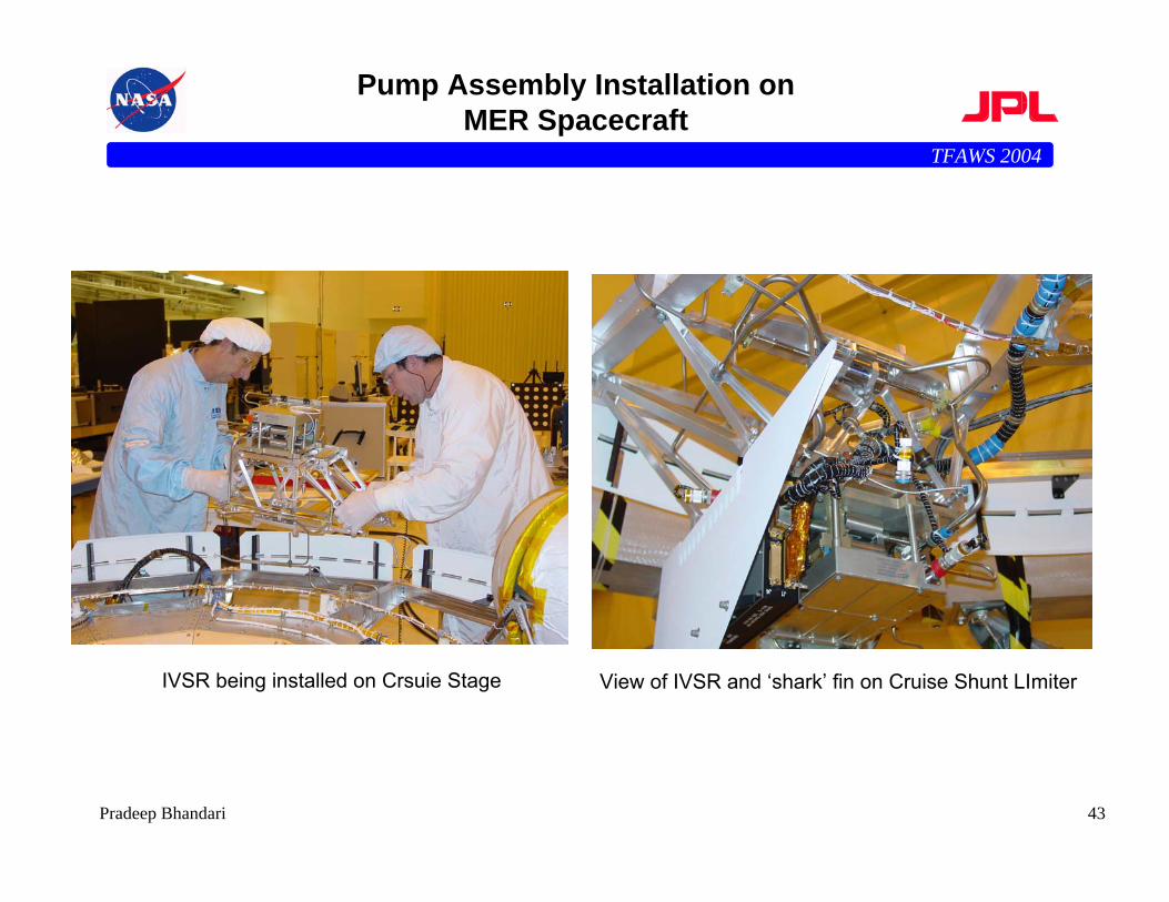
Pump Assembly Installation on MER Spacecraft
IVSR being installed on Crsuie Stage View of IVSR and ‘shark’ fin on Cruise Shunt LImiter
TFAWS 2004
44Pradeep Bhandari
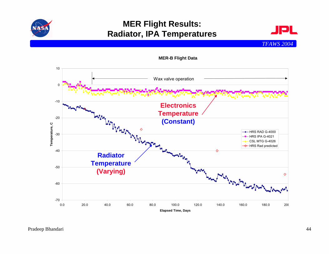
MER Flight Results:Radiator, IPA Temperatures
MER-B Flight Data
-70
-60
-50
-40
-30
-20
-10
0
10
0.0 20.0 40.0 60.0 80.0 100.0 120.0 140.0 160.0 180.0 200
Elapsed Time, Days
Tem
pera
ture
, C
HRS RAD G-4000HRS IPA G-4021CSL MTG G-4026HRS Rad predicted
Wax valve operation
Electronics Temperature (Constant)
Radiator Temperature
(Varying)
TFAWS 2004
45Pradeep Bhandari
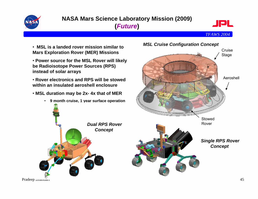
NASA Mars Science Laboratory Mission (2009) (Future)
• MSL is a landed rover mission similar to Mars Exploration Rover (MER) Missions
• Power source for the MSL Rover will likely be Radioisotope Power Sources (RPS) instead of solar arrays
• Rover electronics and RPS will be stowed within an insulated aeroshell enclosure
• MSL duration may be 2x- 4x that of MER• 9 month cruise, 1 year surface operation
MSL Cruise Configuration Concept CruiseStage
StowedRover
Aeroshell
Dual RPS RoverConcept
Single RPS RoverConcept
TFAWS 2004
46Pradeep Bhandari
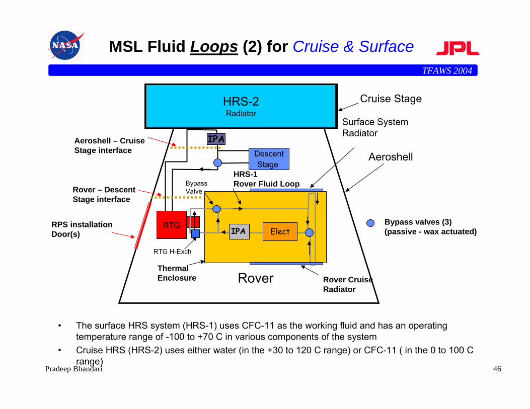
MSL Fluid Loops (2) for Cruise & Surface
• The surface HRS system (HRS-1) uses CFC-11 as the working fluid and has an operating temperature range of -100 to +70 C in various components of the system
• Cruise HRS (HRS-2) uses either water (in the +30 to 120 C range) or CFC-11 ( in the 0 to 100 C range)
Aeroshell
IPA
Cruise Stage
HRS-1 Rover Fluid Loop
Rover
IPA ElectRTG
ThermalEnclosure
DescentStage
Rover Cruise Radiator
Surface SystemRadiator
RTG H-Exch
Bypass Valve
Bypass valves (3) (passive - wax actuated)
HRS-2Radiator
Rover – Descent Stage interface
Aeroshell – Cruise Stage interface
RPS installation Door(s)
TFAWS 2004
47Pradeep Bhandari
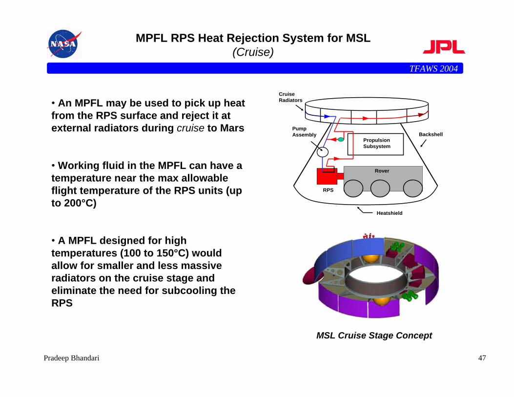
MPFL RPS Heat Rejection System for MSL(Cruise)
• An MPFL may be used to pick up heat from the RPS surface and reject it at external radiators during cruise to Mars
• Working fluid in the MPFL can have a temperature near the max allowable flight temperature of the RPS units (up to 200°C)
• A MPFL designed for high temperatures (100 to 150°C) would allow for smaller and less massive radiators on the cruise stage and eliminate the need for subcooling the RPS
MSL Cruise Stage Concept
Rover
PropulsionSubsystem
RPS
Backshell
Heatshield
CruiseRadiators
PumpAssembly
TFAWS 2004
48Pradeep Bhandari
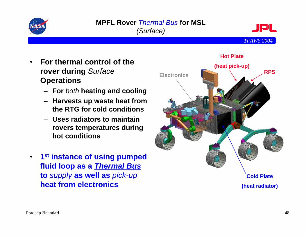
MPFL Rover Thermal Bus for MSL(Surface)
• For thermal control of the rover during SurfaceOperations– For both heating and cooling– Harvests up waste heat from
the RTG for cold conditions– Uses radiators to maintain
rovers temperatures during hot conditions
• 1st instance of using pumped fluid loop as a Thermal Busto supply as well as pick-upheat from electronics
RPS
Hot Plate
(heat pick-up)
Cold Plate
(heat radiator)
Electronics
TFAWS 2004
49Pradeep Bhandari
High Temperature Loops
• NASA/JPL (Mars Technology Program) would like to develop Mechanically Pumped Fluid Loop heat rejection technology for thenext generation of Mars Missions
• Flight Heritage MPFLs used on Mars Pathfinder and Mars Exploration Rover missions is insufficient for rejecting large heat loads or operating at high temperatures
• A new high temperature MPFL design for future robotic missions will be investigated:
• Design to system constraints
• Select optimal working fluid for the MPFL
• Begin development testing to investigate pump performance and material compatibility in a high temperature environment
TFAWS 2004
50Pradeep Bhandari
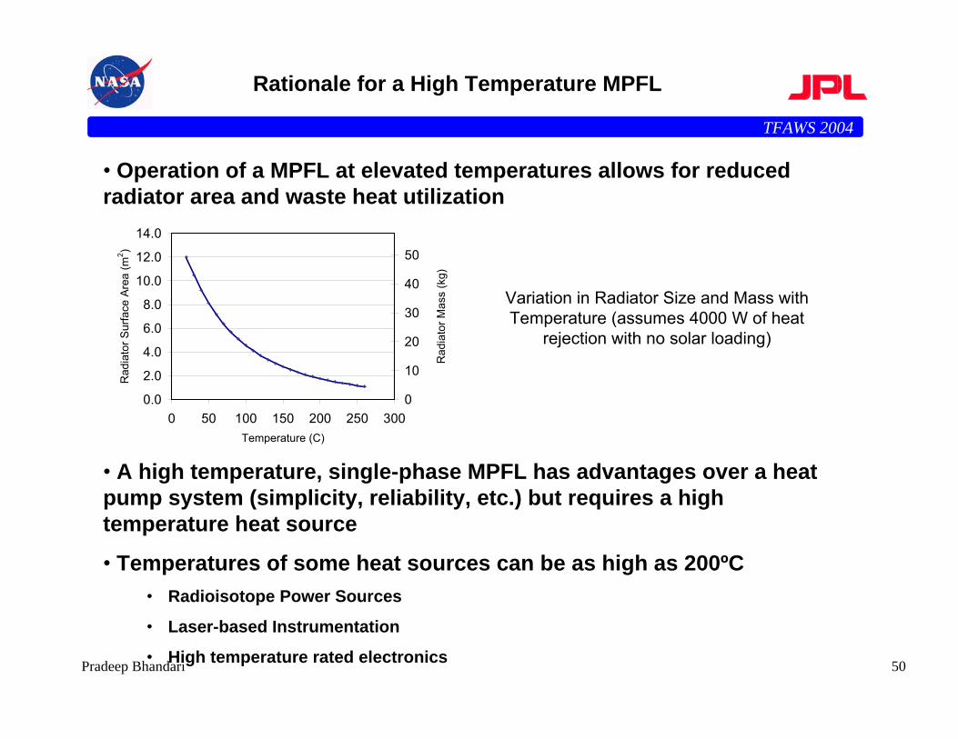
Rationale for a High Temperature MPFL
• Operation of a MPFL at elevated temperatures allows for reducedradiator area and waste heat utilization
• A high temperature, single-phase MPFL has advantages over a heat pump system (simplicity, reliability, etc.) but requires a high temperature heat source
• Temperatures of some heat sources can be as high as 200ºC • Radioisotope Power Sources
• Laser-based Instrumentation
• High temperature rated electronics
0.0
2.0
4.0
6.0
8.0
10.0
12.0
14.0
0 50 100 150 200 250 300Temperature (C)
Rad
iato
r Sur
face
Are
a (m
2 )
0
10
20
30
40
50
Rad
iato
r Mas
s (k
g)
Variation in Radiator Size and Mass with Temperature (assumes 4000 W of heat
rejection with no solar loading)
TFAWS 2004
51Pradeep Bhandari
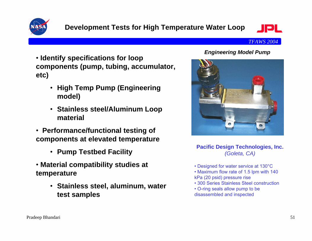
Development Tests for High Temperature Water Loop
Pacific Design Technologies, Inc.(Goleta, CA)
• Designed for water service at 130°C• Maximum flow rate of 1.5 lpm with 140 kPa (20 psid) pressure rise • 300 Series Stainless Steel construction• O-ring seals allow pump to be disassembled and inspected
• Identify specifications for loop components (pump, tubing, accumulator, etc)
• High Temp Pump (Engineering model)
• Stainless steel/Aluminum Loop material
• Performance/functional testing of components at elevated temperature
• Pump Testbed Facility
• Material compatibility studies at temperature
• Stainless steel, aluminum, water test samples
Engineering Model Pump
TFAWS 2004
52Pradeep Bhandari
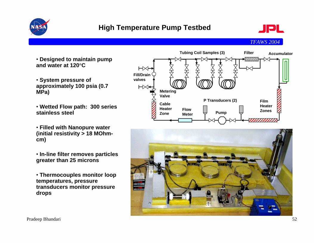
• Designed to maintain pump and water at 120°C
• System pressure of approximately 100 psia (0.7 MPa)
• Wetted Flow path: 300 series stainless steel
• Filled with Nanopure water (initial resistivity > 18 MOhm-cm)
• In-line filter removes particles greater than 25 microns
• Thermocouples monitor loop temperatures, pressure transducers monitor pressure drops
High Temperature Pump Testbed
Tubing Coil Samples (3)
P Transducers (2)
AccumulatorFilter
Flow Meter Pump
Film Heater Zones
Fill/Drain valves
Metering Valve
Cable Heater Zone
TFAWS 2004
53Pradeep Bhandari
Material Compatibility Coupon Tests
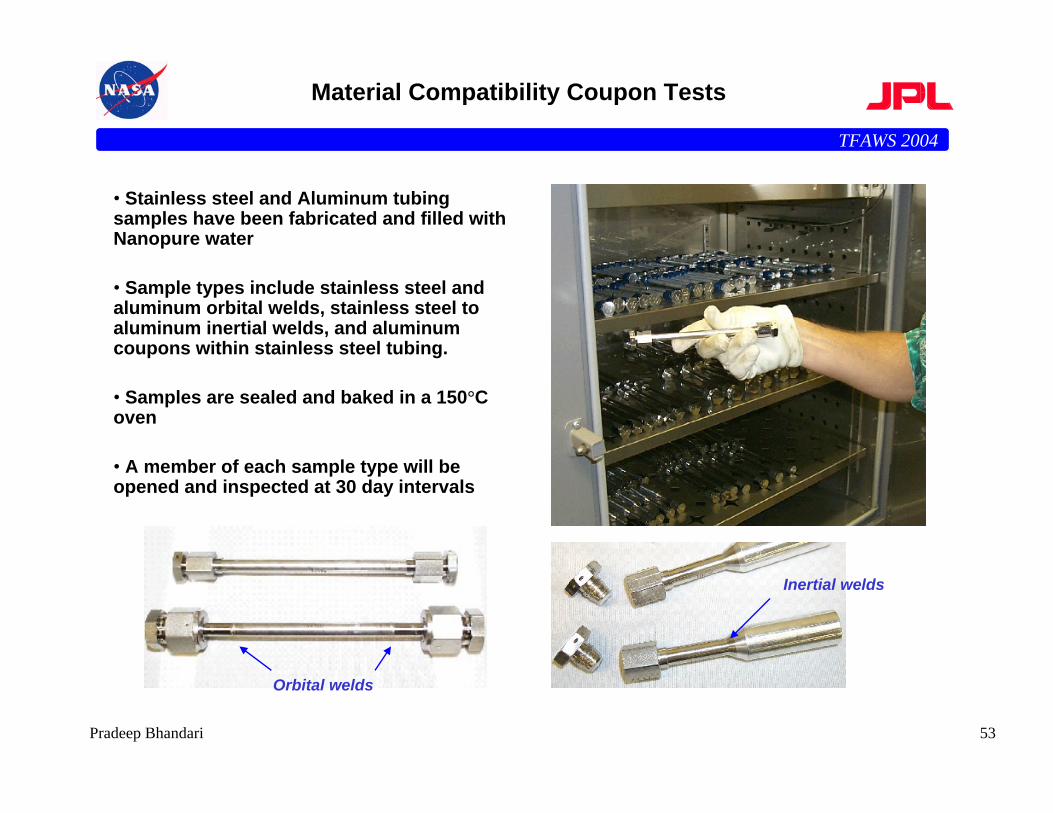
• Stainless steel and Aluminum tubing samples have been fabricated and filled with Nanopure water
• Sample types include stainless steel and aluminum orbital welds, stainless steel to aluminum inertial welds, and aluminum coupons within stainless steel tubing.
• Samples are sealed and baked in a 150°C oven
• A member of each sample type will be opened and inspected at 30 day intervals
Orbital welds
Inertial welds
TFAWS 2004
54Pradeep Bhandari
Next Generation Loops
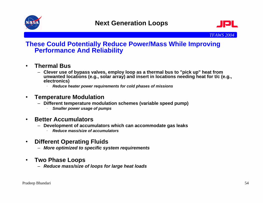
These Could Potentially Reduce Power/Mass While Improving Performance And Reliability
• Thermal Bus– Clever use of bypass valves, employ loop as a thermal bus to "pick up" heat from
unwanted locations (e.g., solar array) and insert in locations needing heat for t/c (e.g., electronics)
· Reduce heater power requirements for cold phases of missions
• Temperature Modulation– Different temperature modulation schemes (variable speed pump)
· Smaller power usage of pumps
• Better Accumulators– Development of accumulators which can accommodate gas leaks
· Reduce mass/size of accumulators
• Different Operating Fluids– More optimized to specific system requirements
• Two Phase Loops– Reduce mass/size of loops for large heat loads
TFAWS 2004
55Pradeep Bhandari
Acknowledgements
• The research described in this paper was performed at the Jet Propulsion Laboratory, California Institute of Technology, under a contract with the National Aeronautics and Space Administration
• The following is a subset of many folks at JPL who have contributed to the successful development and implementation of this technology
– Andre Yavrouian (Chemistry)– Jack Patzold (Implementation)– Paul McGrath (Pump Contract Manager)– Dave Bame (Implementation)– Partha Shakkottai (Venting Analysis)
• Pacific Design Technology for designing, manufacturing and supplying the pump assembly
TFAWS 2004
56Pradeep Bhandari
Summary
• Active heat rejection systems consisting of mechanically pumped single-phase liquid were designed and developed for Mars Pathfinder (MPF) and the two Mars Exploration Rover Missions
• The successful flight demonstration (3 out of 3) of these mechanically pumped cooling loops in these missions has shown that active cooling systems can be reliably used in deep space missions
• The Mars Science Laboratory (MSL) Mission (2009 launch) has base-lined twomechanically pumped fluid loop systems
– One for cruise to cool the RTG, one for thermal control of the rover– The rover loop is a true thermal bus– To achieve thermal control of the rover, it simultaneously picks up heat from the RTG
and rejects excess heat to radiator
• The next generation of loops would extend the state of the art to higher heat rates and fluxes by using two-phase flow, lighter accumulators and more choices of working fluids to make them true thermal buses
• The flexibility provided by mechanically pumped fluid thermal control systems in the design, integration, test, and flight operation of spacecraft makes this thermal control system a very attractive and reliable system for future missions

TFAWS 2004
57Pradeep Bhandari
List of Papers Published by the JPL Team onMechanically Pumped Fluid Loops

![[PPT]Presentación de PowerPoint · Web viewEnergy Storage Methods Energy Storage Mechanical Chemical Electromagnetic Thermal Pumped Hydro Compressed Air (CAES) Flywheel Batteries](https://img.pdfslide.us/doc/110x75/5ac623e37f8b9a333d8e3c59/pptpresentacin-de-powerpoint-viewenergy-storage-methods-energy-storage-mechanical.jpg)