Embed Size (px)
Citation preview
Clemson UniversityTigerPrints
All Theses Theses
12-2011
The Design of a Haptic Device for Training andEvaluating Surgeon and Novice LaparoscopicMovement SkillsRyan BontregerClemson University, [email protected]
Follow this and additional works at: https://tigerprints.clemson.edu/all_theses
Part of the Robotics Commons
This Thesis is brought to you for free and open access by the Theses at TigerPrints. It has been accepted for inclusion in All Theses by an authorizedadministrator of TigerPrints. For more information, please contact [email protected].
Recommended CitationBontreger, Ryan, "The Design of a Haptic Device for Training and Evaluating Surgeon and Novice Laparoscopic Movement Skills"(2011). All Theses. 1249.https://tigerprints.clemson.edu/all_theses/1249
THE DESIGN OF A HAPTIC DEVICE FOR TRAINING
AND EVALUATING SURGEON AND NOVICE
LAPAROSCOPIC MOVEMENT SKILLS
A Thesis
Presented to
the Graduate School of
Clemson University
In Partial Fulfillment
of the Requirements for the Degree
Master of Science
Computer Engineering
by
Ryan Bontreger
August 2011
Committee:
Dr. Tim Burg, Committee Chair
Dr. Darren Dawson
Dr. Ian Walker
ii
ABSTRACT
As proper levels of force application are necessary to ensure patient safety,
and training hours with an expert on live subjects are difficult, enhanced
computer-based training is needed to teach the next generation of surgeons.
Considering the role of touch in surgery, there is a need for a device capable of
discerning the haptic ability of surgical trainees. This need is amplified by
minimally invasive surgical techniques where a surgeon’s sense of tissue
properties comes not directly through their own hands but indirectly through the
tools. A haptic device capable of producing a realistic range of forces and motions
that can be used to test the ability of users to replicate salient forces in specific
maneuvers is proposed. This device also provides the opportunity to use
inexpensive haptic trainers to educate surgeons about proper force application.
A novel haptic device was designed and built to provide a simplified
analogy of the forces and torques felt during free tool motion and constrained
pushing, sweep with laparoscopic instruments. The device is realized as a single-
degree-of-freedom robotic system controlled using real-time computer hardware
and software. The details of the device design and the results of testing the design
against the specifications are presented. A significant achievement in the design is
the use of a two-camera vision system to sense the user placement of the input
device. The capability of the device as a first-order screening tool to distinguish
between novices and expert surgeons is described.

iii
ACKNOWLEDGMENTS
To all the mentors along the way and those more knowledgeable who shared their
gifts with me, thank you.

iv
TABLE OF CONTENTS
Page
TITLE PAGE .................................................................................................................... i
ABSTRACT ..................................................................................................................... ii
ACKNOWLEDGMENTS .............................................................................................. iii
LIST OF TABLES ........................................................................................................... v
LIST OF FIGURES ........................................................................................................ vi
CHAPTER
I. INTRODUCTION ......................................................................................... 1
Physiology of human contact ................................................................... 1
Haptic devices and interfaces ................................................................... 6
Laparoscopic skill trainers ..................................................................... 12
Goals of this project ............................................................................... 17
II. DESIGN AND IMPLEMENTATION OF THE
HAPTIC MECHANISMS ..................................................................... 20
Requirements ......................................................................................... 20
Robot mechanism design ....................................................................... 29
Support Structure ................................................................................... 39
Establishment of length sensing requirements ....................................... 42
Integrated Control System ..................................................................... 68
User interface / Graphics ....................................................................... 69
System Analysis ..................................................................................... 70
III. RESULTS .................................................................................................... 71
Sweep ..................................................................................................... 71
Free-tool ................................................................................................. 81
IV. CONCLUSIONS.......................................................................................... 86
Analysis of Results ................................................................................ 86
Future work ............................................................................................ 87
REFERENCES .............................................................................................................. 90

v
LIST OF TABLES
1.1 Description of Mechanoreceptors in the skin ................................................ 4
2.1 Lab test motor data....................................................................................... 33
3.1 Stiff Spring Data .......................................................................................... 80
3.2 Soft Spring Data .......................................................................................... 80
3.3 Mean and standard deviation for stiff spring data ....................................... 81
3.4 Mean and standard deviation for soft spring data ....................................... 81

vi
LIST OF FIGURES
1.1 A comparison of the three systems of human contact that can
be evoked when interacting with an object. Cutaneous
touch (left) is characterized by a light, fingertip contact
with the surface of the device. Kinesthetic touch (middle)
involves limb positions as part of sensing of the relative
position and orientation of an object. Haptic touch (right)
adds dynamic object properties, e.g. inertia, to the sensing
process...................................................................................................... 3
1.2 PHANToM Omni (left) is a four degree-of-freedom haptic
device with three actuated joints (red arrows) and one
passive joint (green arrow). The Novint Falcon (right) has
three actuated linear degrees-of-freedom that form a three
inch cubic workspace. ............................................................................ 10
1.3 Four minimal haptic skills are proposed that span the haptic
interactions in laparoscopy. ................................................................... 18
2.1 Surgeon sweeping tissues away from the tool insertion point ..................... 21
2.2 Mass-Spring-Damper system proposed as an analogy for the
sweep task .............................................................................................. 22
2.3 Multiple ways to view the free-tool analogy ............................................... 24
2.4 Real and Virtual World Relationship ........................................................... 26
2.5 Block diagram of input-output system requirements ................................... 27
2.6 Model of xPC target setup ........................................................................... 29

vii
2.7 Schematic of the Functional Requirement of the Free-Tool and
Sweep Analogies. The commonality of these analogies
allows a single realization where a real laparoscopic tool is
actuated by an electric motor. ................................................................ 30
2.8 Simplified conceptual circuit diagram ......................................................... 32
2.9 Motor torque generation testing apparatus .................................................. 33
2.10 Complete Simulink system to demonstrate motor control ........................... 35
2.11 Plot of Motor Current Control – Step .......................................................... 36
2.12 Plot of Motor Current Control – Sinusoidal ................................................ 37
2.13 Plot of Motor Current Control – Realistic ................................................... 38
2.14 Overhead view of the range of tool motion ................................................. 40
2.15 User view of the enclosure ........................................................................... 41
2.16 Open view of the enclosure.......................................................................... 41
2.17 Covered view of the enclosure ..................................................................... 42
2.18 Optical sensor setup ..................................................................................... 44
2.19 Optical sensor prototype .............................................................................. 45
2.20 Wheel-based encoder setup.......................................................................... 46
2.21 Overhead view through the camera ............................................................. 49
2.22 Overhead thresholded view.......................................................................... 50
2.23 Single camera location for full range of motion viewing ............................ 52
viii
2.24 An overhead view of an in-plane camera field of view ............................... 53
2.25 An overhead view of two in-plane cameras field of view ........................... 54
2.26 Two Camera Algorithm ............................................................................... 55
2.27 Dual Camera View ....................................................................................... 56
2.28 In-plane camera thresholding ....................................................................... 57
2.29 Tip identification accuracy .......................................................................... 58
2.30 Identifying Single Camera Projection Line ................................................. 59
2.31 Identifying Intersection of Projection Lines ................................................ 60
2.32 Insertion length measurement sensor reading, ideal case. ........................... 62
2.33 Insertion length measurement sensor reading, worst-case ........................... 62
2.34 Insertion length sensor reading and encoder position over time.
Insertion length fixed at 185 mm. .......................................................... 64
2.35 Insertion length sensor reading and encoder position over time.
Insertion length fixed at 135 mm. .......................................................... 65
2.36 Insertion length sensor reading and encoder position over time.
Insertion length fixed at 245 mm. .......................................................... 66
2.37 Filtered insertion length sensor reading and encoder position
over time. Insertion length ranging from 30mm to 220mm................... 67
2.38 System Architecture ..................................................................................... 68
2.39 Screenshot of Training Interface .................................................................. 70
3.1 User starting the sweep task ......................................................................... 72

ix
3.2 Close up view of the centering notch ........................................................... 73
3.3 The user moving the tool to apply a force magnitude IV ............................ 74
3.4 Front view (with cover removed) showing the sweep device in
use .......................................................................................................... 75
3.5 Surgeon stiff spring data .............................................................................. 77
3.6 Novice stiff spring data ................................................................................ 77
3.7 Surgeon soft spring data............................................................................... 79
3.8 Novice soft spring data ................................................................................ 79
3.9 A Photograph of the response instrument for the Free-Tool
analogy experiments. The total height of the device is 1m.
The user side is shown in B, without a scale and the proctor
side is shown in C. with the response scale. ......................................... 82
3.10 Surgeon Free-tool Regression plots ............................................................. 84
3.11 Novice Free-tool Regression plots ............................................................... 84
1
CHAPTER 1
INTRODUCTION
The goal of this work is to design, build, and demonstrate a haptic interface device
that can be used in the evaluation and training of laparoscopic surgeons. This thesis is
organized to follow the research and design process executed in fulfilling this goal.
Chapter 1 contains the background information on human touch and perception,
laparoscopic surgery training methods, and computer controlled haptic devices that points
to a new opportunity for creating a mechatronic device that can advance the art of
surgeon training. This background research leads to the specifications of a haptic
interface device described in Chapter 2. Chapter 2 contains the details of the device
design and the results of testing the design against the specifications. A significant
achievement in the design is the use of a two-camera vision system to sense the user
placement of the input device. The experimental results of using the device as a first-
order screening tool to distinguish between novices and expert surgeons is described in
Chapter 3. General conclusions about the efficacy and future of the device are
formulated in Chapter 4.
1.1 Physiology of Human Contact
To gain an appreciation for why the use of haptic sensations would be beneficial in
minimally invasive surgical training, an understanding of the sense of haptic perception
and how it compares to other touch related sensations must first be considered. The sense

2
of touch, since it was first described as one of the five senses by Aristotle, has been
unique among the senses. Unlike the other senses, which have a clear and distinct organ
associated with the sensation, namely the eyes, ears, nose and mouth, touch does not have
the same distinction. Several attempts have been made to define touch in a direct method
[1], and many different ways of defining the different touch modalities have resulted.
Some early researchers broke down the touch sensations into muscles, joints, and
combined all other sensations into a third group [2], where others divided the sensations
into five: pressure, warm, cold, pain, and kinesthesis [3]. Modern researchers have
grouped the associated sensations from a biological structural standpoint, which was not
possible for researchers in the early 1900s [4]. The terminology is still somewhat varied,
so here, we will use the terms used by Klatzky and Lederman. They defined the three
systems as “cutaneous, kinesthetic, and haptic”, basing these divisions from the
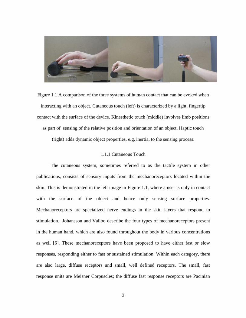
underlying neural inputs [5]. Figure 1.1 shows a general comparison of the three systems
that will now be described in detail.
3
Figure 1.1 A comparison of the three systems of human contact that can be evoked when
interacting with an object. Cutaneous touch (left) is characterized by a light, fingertip
contact with the surface of the device. Kinesthetic touch (middle) involves limb positions
as part of sensing of the relative position and orientation of an object. Haptic touch
(right) adds dynamic object properties, e.g. inertia, to the sensing process.
1.1.1 Cutaneous Touch
The cutaneous system, sometimes referred to as the tactile system in other
publications, consists of sensory inputs from the mechanoreceptors located within the
skin. This is demonstrated in the left image in Figure 1.1, where a user is only in contact
with the surface of the object and hence only sensing surface properties.
Mechanoreceptors are specialized nerve endings in the skin layers that respond to
stimulation. Johansson and Vallbo describe the four types of mechanoreceptors present
in the human hand, which are also found throughout the body in various concentrations
as well [6]. These mechanoreceptors have been proposed to have either fast or slow
responses, responding either to fast or sustained stimulation. Within each category, there
are also large, diffuse receptors and small, well defined receptors. The small, fast
response units are Meisner Corpuscles; the diffuse fast response receptors are Pacinian

4
Corspuscles. The sustained stimulation response units are Merkel cell neurite complexes
for small response fields and the diffuse response field units are Ruffini endings. The fast
response mechanoreceptors are closer to the surface of the skin than the slow response
receptors [6]. Also included in this category of mechanoreceptors are the hair follicle
receptors, although the analysis done by Johansson and Vallbo on the front of the fingers
and hand would not include these receptors. This sort of stimulation is related to whether
an object is in contact with an observer, and how much contact is being made. A
summary is found in Table 1.1 below.
Small field Large field
Fast response Meisner Corpuscles Pacinian Corspuscles
Slow response Merkel discs Ruffini endings
Table 1.1 Description of Mechanoreceptors in the Skin
The direct role of cutaneous sensing in most surgeries is small since surgeries
involve very little direct tissue contact. Open surgeries are typically performed with
gloved hands, with many professional organizations, including the Centers for Disease
Control and Prevention (CDC) recommending using double gloves [7]. What little
cutaneous sensing that occurs though gloved hands is lost in the case of laparoscopic
surgery where all tissue contact is through the laparoscopic tool leveraged at the trocar
insertion point. However, the sensing modes are not independent [4] and cutaneous
sensing does support the more dominant sensing modes present during laparoscopic
surgery.

5
1.1.2 Kinesthetic Touch
Kinesthesis was defined by Gibson as the sensitivity of the joints, both with and
without the muscle sense [1]. We find similar definitions from Clark and Horch, noting
that kinesthesis literally means a sense of movement, but that current usage refers more
towards a sensing of limb positions [8]. Proprioception, which is synonymous with
kinesthesia, comes from three types of mechanoreceptors in the muscles. Two of these
mechanoreceptors respond to stretching, and the third is associated with the sensing of
the tendon reflex [9]. This is demonstrated in the middle picture of Figure 1.1. In this
example, the information conveyed in the kinesthetic sense is the location of a stimulus.
The stimulus is noted by the cutaneous contact, relative to the person, and is derived from
the angle in the elbow, wrist, and finger joints. The sensory information about the relative
positions and parts of the body, and the associated muscular effort needed is kinesthetic
in nature, and while it is definitely part of haptic perception, kinesthetics is not typically
considered to be a part of force application or environmental inventory [4].
1.1.3 Haptic Perception
The definition of haptics varies greatly in content between researchers, but the
general consensus is that haptic sensing requires some sense of activity. This differs from
the passive inventory of the environment where the observer only experiences sensation
of the environment in relation to the observer, such as temperature, winds, or objects in
contact. In practice, most of our tactual perception and tactually controlled performance
is considered haptic in nature. This is illustrated in the picture on the far right in Figure
1.1, where the tool is being picked up and manipulated. Several different exploratory
6
methods associated with haptic perception have been described. Rubbing in a lateral
motion against a surface, for instance, gives the sensations of texture. However, this is
not truly cutaneous or kinesthetic in nature, but falls in between the two. Other motions,
such as pressing against a surface to sense hardness or holding an object unsupported to
sense weight are also haptic explorations. Other techniques like wrapping hands around
an object or following contours provide shape information are, like the other methods,
combinations of cutaneous and kinesthetic touch with movement on the part of the
observer [10]. With this necessity for movement, a haptic device needs to be capable of
moving as well as exerting forces back to the user that would come as a result of contact
with the environment. A suitable device for laparoscopic training should primarily cater
to the haptic perception of the user but must also be designed such that the senses of
cutaneous and kinesthetic touch support the primary touch illusion of the simulator.
1.2 Haptic Devices and Interfaces
In order to touch or feel a virtual or teleoperator system, a haptic interface is
employed. In general a haptic device leverages the touch modalities described above to
create an artificial perception on a user. Haptic devices are most frequently used as
computer interface devices in gaming and training systems. Traditional computer
peripherals, such as the keyboard and mouse, are passive devices. These devices are only
used as a sensor of the user’s motion or state, and despite the interest in these devices
from usability and ergonomic studies, these devices are uninteresting in the field of
haptics. The important principle that differentiates haptic devices from general user
interface devices is the two-way method of communication, where the user provides
7
input and receives touch excitation output via the same device through some actuator
forces [11]. Most commercial devices fall within two categories of control
implementation, impedance and admittance. Within these categories, a wide variety of
designs exist [11].
1.2.1 Impedance devices
An impedance device receives a displacement input from the user and produces
an appropriate reaction force according to an environmental model. For example, a
simple spring model for the virtual environment would produce a force directly
proportional to the input displacement. Many popular devices that have seen some
general consumer success, such as the Novint Falcon and the Sensable PHANToM series,
are examples of impedance devices. As a result, the user will feel the mass and friction
of the physical device in addition to the virtual forces generated by the system. Because
of this, impedance devices tend to be very lightly built, as to minimize the force and
friction generated by the physical device that may also influence the user’s ability to
accurately sense the virtual system [12]. The primary advantage of impedance devices is
that there exists a wide variety of commercially available, low-cost sensors that can be
used to measure the displacement of a robotic device. For example, low-cost encoders
facilitate angular position sensing.
While the basic control structure is very simple, the control of these devices
presents challenges. One approach for stabilizing a haptic system is to guarantee passivity
of the elements of the system. The elements of the system are the human operator and the
8
haptic device. As active movements of humans are below 10 Hz, the human is assumed
to be passive for high frequency dynamics. Thus, stability can derive only from making
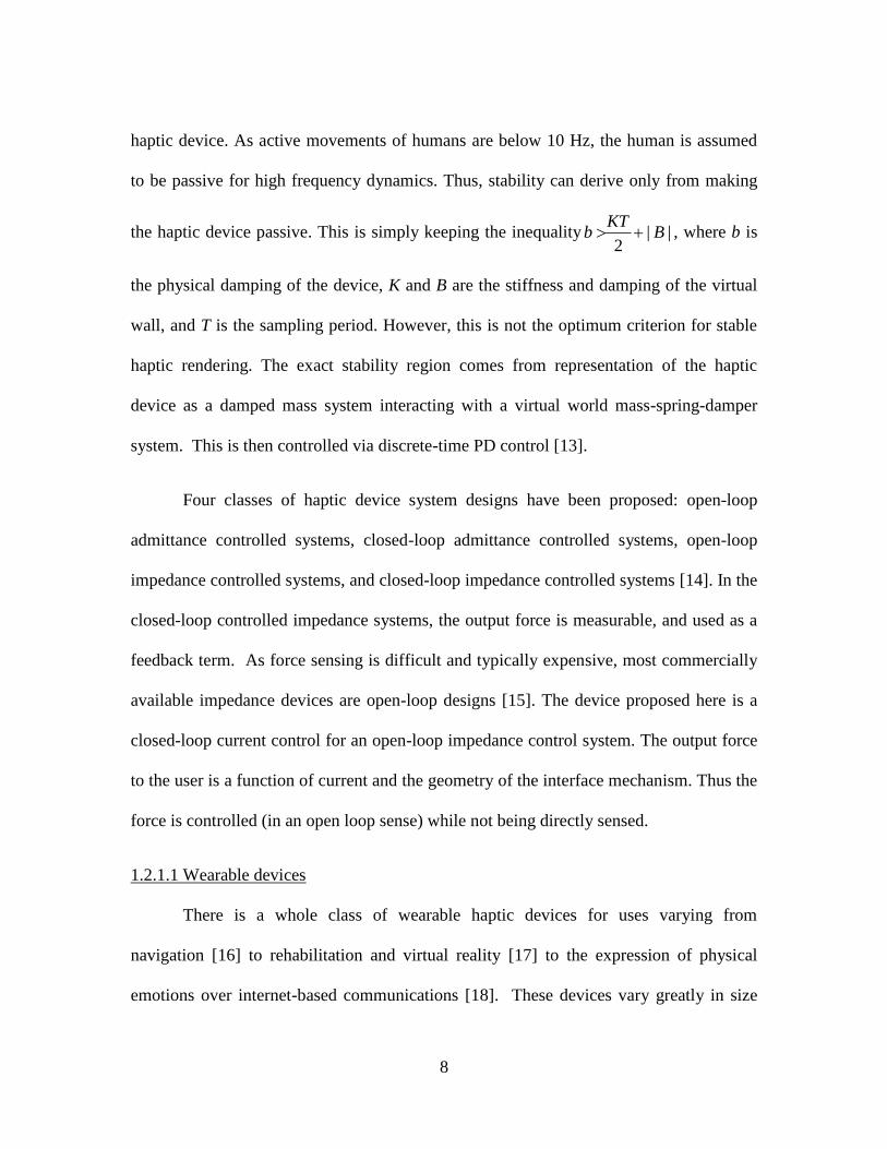
the haptic device passive. This is simply keeping the inequality | |2
KTb B , where b is
the physical damping of the device, K and B are the stiffness and damping of the virtual
wall, and T is the sampling period. However, this is not the optimum criterion for stable
haptic rendering. The exact stability region comes from representation of the haptic
device as a damped mass system interacting with a virtual world mass-spring-damper
system. This is then controlled via discrete-time PD control [13].
Four classes of haptic device system designs have been proposed: open-loop
admittance controlled systems, closed-loop admittance controlled systems, open-loop
impedance controlled systems, and closed-loop impedance controlled systems [14]. In the
closed-loop controlled impedance systems, the output force is measurable, and used as a
feedback term. As force sensing is difficult and typically expensive, most commercially
available impedance devices are open-loop designs [15]. The device proposed here is a
closed-loop current control for an open-loop impedance control system. The output force
to the user is a function of current and the geometry of the interface mechanism. Thus the
force is controlled (in an open loop sense) while not being directly sensed.
1.2.1.1 Wearable devices
There is a whole class of wearable haptic devices for uses varying from
navigation [16] to rehabilitation and virtual reality [17] to the expression of physical
emotions over internet-based communications [18]. These devices vary greatly in size
9
and shape, from force actuators attached to a user to exoskeleton devices worn over
limbs. There are a few commercially available devices, notably the CyberGrasp from
CyberGlove Systems [19], but because of the unique requirements of each individual
application when wearable devices are used, most current devices are custom designed
research prototypes. These devices are limited in the forces they can actuate, because
they are worn on the user and the use of larger motors would encumber the users [20].
1.2.1.2 Desktop devices
Desktop devices are different from the wearable devices in that the device is in a
fixed location, and only a part of the device is movable, i.e. a fixed base with a movable
user interface. Most commercially available devices are in this category, including the
PHANToM line of devices from SenseAble [21], the Falcon from Novint [22], the
delta.x, omega.x, and sigma.x devices from Force Dimension [23], and other joystick-like
devices from Microsoft, Logitech, and others. These devices are available for almost any
budget and typically the cost is proportional to range of motion, position sensing
accuracy, and number of degrees-of-freedom of movement and degrees-of-freedom with
force actuation. Desktop devices are frequently limited to a very small workspace,
generally a cube a few inches on each side, so their typical application is in fine motor
skill tasks, like virtual sculpting [24] [25], where the range of motion is small but the
range of motion and haptic sensation mimics a real environment [26]. Also, this category
of devices has found a market in the commercial entertainment sector, with popular
games supporting the use of a haptic input device. The Novint Falcon is marketed this
way, featuring an optional pistol-grip styled handle to be used in first-person shooting
10
games like the Half-Life series from Valve, Battlefield series from EA, and several other
independent games [22].
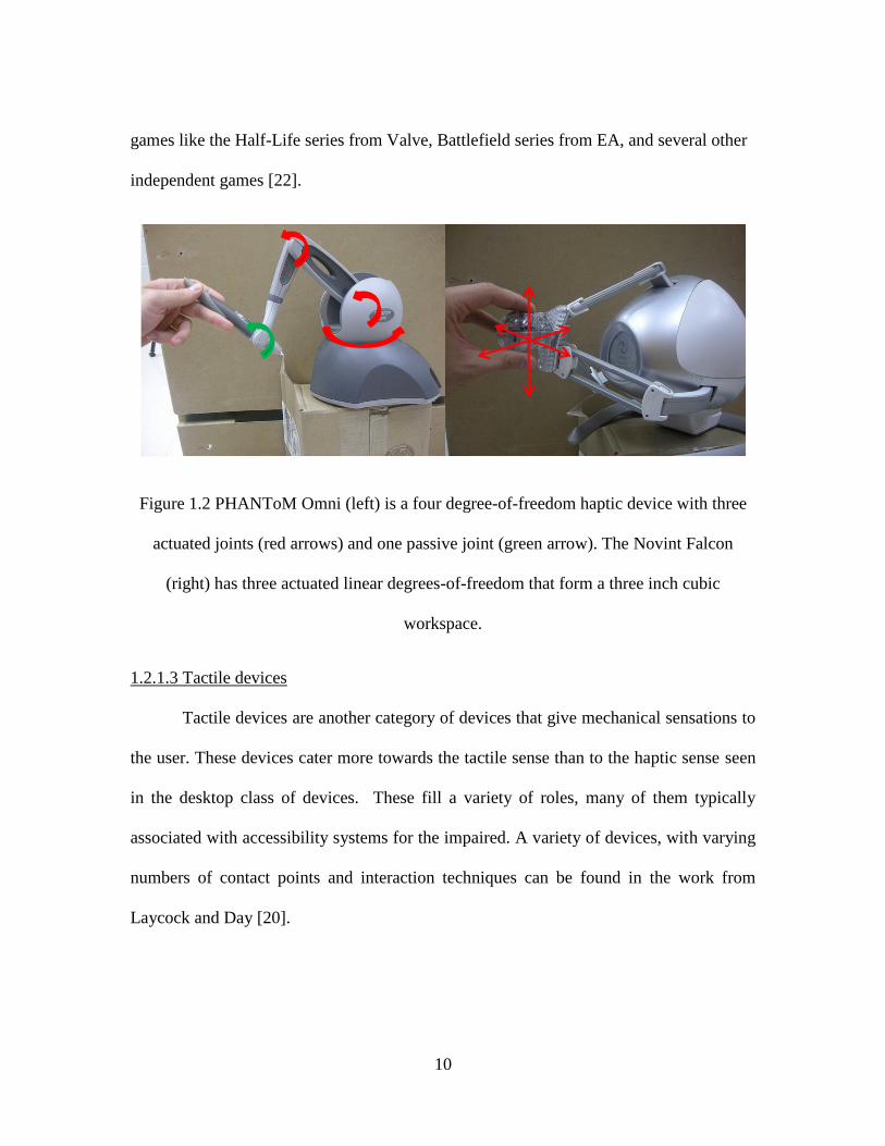
Figure 1.2 PHANToM Omni (left) is a four degree-of-freedom haptic device with three
actuated joints (red arrows) and one passive joint (green arrow). The Novint Falcon
(right) has three actuated linear degrees-of-freedom that form a three inch cubic
workspace.
1.2.1.3 Tactile devices
Tactile devices are another category of devices that give mechanical sensations to
the user. These devices cater more towards the tactile sense than to the haptic sense seen
in the desktop class of devices. These fill a variety of roles, many of them typically
associated with accessibility systems for the impaired. A variety of devices, with varying
numbers of contact points and interaction techniques can be found in the work from
Laycock and Day [20].
11
1.2.2 Admittance devices
An admittance device is driven by an input force from the user and then uses
these forces to constrain the user’s position according to an environmental model. For
example, if the environment is model as a simple spring then a constant user input force
should produce a proportional displacement of the device. Although these are less widely
used than impedance devices, they are still frequently used in industrial robotic
applications or in other situations where slow, precise movements are necessary [27].
There are a few commercially available desktop devices that are admittance-based. One
such commercially-available desktop device is the HapticMaster. Some of the benefits of
an admittance device include the ability to provide a very high stiffness and large forces
[12]. However, force sensing is significantly more difficult and thus more expensive
compared to position sensing.
1.2.3 Niche-specific devices
Devices can easily be created for specific applications and may not fall into the
earlier categories. These devices include devices from programmable music keyboards,
weight scales, to augmented mice with brakes, force-actuated knobs, deformable planar
surfaces, and many more. These devices are explicitly tailored for the specific
application and expected use and illustrate how the design of the electromechanical
interface mechanism can be a critical portion of the haptic system design [28].
Another developing niche of note is the use of haptic devices in the field of
prosthetics and limb replacement. Like the exoskeleton devices discussed earlier, these
12
are designed to be worn by the user. However, instead of having virtual objects that are
used to formulate the force outputs to the user, real world interactions are used to
calculate these outputs. This class of devices allow for the users to regain lost sensations
with more realistic results than conventional treatments [29].
1.3 Laparoscopic Skill Trainers
The goal of the proposed haptic device is centered on training skills for minimally
invasive surgery, notably laparoscopy1, a brief look at why force application in this field
is important will explain the need for such a device. The first laparoscopic procedures in
humans were performed in 1910 by Hans Christian Jacobaeus [30]. The procedure was
used for examining the condition of patients with tuberculous peritonitis. The tools used
then, a cystoscope2 and Stille trocar, are still used today. The endoscope
3 has been
updated to take advantage of technology advances in video capture and imaging, but the
basics in minimally invasive exploration have not changed. He was also the first to
realize the need for training on animals and cadavers, and the risk of organ injuries with
insertion of the trocar, among other concerns [30].
Laparoscopic surgery has become a preferred option when it is viable. From a
patient’s perspective, the reduced hemorrhaging, smaller incisions, less pain, and shorter
hospital stays are all sought after benefits provided by laparoscopy surgery. However,
the procedures may be more challenging to the surgeons. The limited range of motion,
1 Laparoscopy technically refers only to minimally invasive surgery in the abdominal or pelvic cavity.
2 A cystoscope is now considered a specific type of endoscope for the urinary bladder.
3 Endoscope is the general term that covers all the minimally invasive tools to allow a medical professional
to view inside the body.
13
lack of depth perception, and the inability to directly interact with the tissues with their
hands all make laparoscopy more difficult to perform than standard surgery. In the United
States alone, approximately 420,000 laparoscopic cholecystectomy4 procedures are
performed annually, compared with only another 90,000 traditional open
cholecystectomies annually. In terms of laparoscopic operations, this is the most common
procedure, although many other procedures are now being performed through minimally
invasive techniques now. Some other minimally invasive surgical procedures include
appendectomies, gastrointestinal surgery, bariatric procedures, gynecologic surgery and
urologic operations [31].
1.3.1 Fundamentals of Laparoscopic Surgery
Laparoscopic surgery became commonplace in the early 1990’s, but because of
the learning curve associated with the procedures, an increase in the rate of injuries was
also seen. With no formal metric to establish competency at laparoscopic skills, the
Society of American Gastrointestinal and Endoscopic Surgeons (SAGES) developed the
Fundamentals of Laparoscopic Surgery (FLS) program. The purpose of the FLS is to
establish basic cognitive and technical skills for laparoscopic surgeons [32]. Five manual
skills tasks are included. These are a peg transfer task, a precision cutting task, placement
and securing of a ligating loop, and two suture tasks. These tasks are associated with a
device referred to as a box trainer. Inside a closed box, surgeons perform these tasks
using actual laparoscopic tools, with video feedback through a monitor. These tasks are
graded for speed and precision and test the surgeon’s coordination, ambidexterity,
4 A cholecystectomy is the surgical removal of the gall bladder, frequently performed to treat gall stones
14
bimanual skills, and depth perception. The manual skills tasks are derived from the
McGill Inanimate System for Training and Evaluation of Laparoscopic Skills
(MISTELS), which has been well validated [33].
It is significant that the FLS skill set does not attempt to create a surgical
simulator, the tasks such as peg transfer are not surgical maneuvers and the manipulated
objects are not surgical phantoms. The success of FLS can be attributed to the fact that
this simple set of tasks spans the set of salient skills needed to perform laparoscopic
surgery. It has recently been suggested that FLS spans only the skill set related to eye-
hand coordination [34]. Connecting the FLS idea of minimal skills training with the need
for force perception and application skills in laparoscopic surgery, Singapogu [35] has
suggested that a minimal set of haptic skills can be developed to span the set of haptic
skills needed in laparoscopic surgery.
1.3.2 Current State of Laparoscopy
While in most simple operations, laparoscopy is performed directly by the
surgeons, a quickly growing trend is for robotic-assisted minimally invasive surgery. The
leading system in this area is the da Vinci surgery system from Intuitive Surgical [36].
Originally designed for use by NASA and DARPA for performing remote surgery on the
battlefield or in space, the current systems are widely used in on-site surgery. Currently
more than 1,400 hospitals have the da Vinci system in place [37]. While this has not
replaced open surgery or laparoscopy, the number of procedures being performed through
this robotic system is rapidly increasing. For the da Vinci system, 278,000 procedures
15
were performed in 2010, up 35% from the previous year. More hospitals use robotic
assisted surgery systems, with about 200 new da Vinci systems being installed per year
worldwide. These systems are expensive, costing between 1 and 2.3 million USD
depending on what additional features are included, with instrumentation and tools that
cost another $1,300 to $2,200 per procedure [38].
Some of the issues mentioned with laparoscopy in general have been addressed in
the da Vinci system. For video, a 3D camera system and display is used, so that depth
perception is preserved for the surgeons. Also, the system does relay force feedback
sensations to the surgeon during the procedure [37]. The location of the sensors in this
system design relays the instrument-organ contact forces to the surgeon only, free from
the interfering signals of the abdominal wall or friction with the trocar. The advantages
of a system like this, where the surgeon’s motions can be reduced to a smaller scale to
allow for more precise motion, or to filter out hand jitters, are quite powerful tools in
today’s minimally invasive operating room. The associated cost makes this robotic
system difficult to justify in simple procedures performed by well-trained surgeons.
1.3.3 Virtual Reality Simulators
One of the first available computer-based simulators, the MIST VR system
focused on the tool movements in a very small range of motion. The MIST VR simulator
consisted of two laparoscopic instruments mounted to a gimbal with motion-detecting
potentiometers and was linked to a PC. The tools available had six degrees-of-freedom,
able to interact with a 10 cm3 volume. This trainer had visual feedback and consisted of
16
six tasks: acquire-place, transfer-place, traversal, withdraw-insert, diathermy, and
manipulation-diathermy [39]. Multiple studies have shown the validity of this trainer,
both as a discriminating measure between novices and experts and in improving the
performance during real surgeries [40].
As technologies improved, newer systems were introduced that implement more
realistic tasks, such as the LAPSIM simulator from Surgical Science. This device also
shows validity in differentiating between novice and expert subjects. With increased
realism in graphics and more complex tasks, including suturing, clip application, lifting,
grasping and general instrument navigation, more complete procedures can be trained
virtually [41].
Most devices that offer haptic feedback offer the feature as an optional addition.
One such device, the LAPmentor II from Simbionix has such capabilities. Like the other
devices mentioned, the proof of validity for this simulator is also documented [42], but
the benefit of haptic feedback has been found to be relatively insignificant. A theory as to
why the haptic feedback did not seem effective in this instance is the compensation for
the lack of feeling by using more visual cues [43]. This study motivated the device
proposed in this thesis to avoid confounding visual feedback in conjunction with haptic
feedback to isolate haptic skills. This also motivated enclosing the system, so that visual
cues simply from seeing the tool would be avoided.
17
1.3.4 Opinions and Findings
In terms of practical results, using haptic feedback has been shown to enhance
force skill learning on abstract motor skills [44]. Furthermore, the use of virtual reality
simulators for laparoscopic skill training has also shown to be effective, even before the
introduction of haptic forces [40]. But as seen with the LAPmentor II, haptic feedback
did not correlate directly to an improvement in abilities. With the potential conflicting
factors from the visual feedback, we look to devise a system that will isolate the haptic
perception from the visual response.
With simulators in general, even when used only in familiarizing the user with the
tool, not the surgical operation itself, the findings have shown performance gains for
trainees [40]. Comparing virtual reality to the traditional box trainer commonly used to
train surgeons to work with the tool, virtual reality training showed gains over the
traditional box trainer. The box trainer has proper haptic feedback, being a mechanical
system, yet did not show as much improvement as a non-haptic LAPSIM system. Both
training methods did show improvement over no training [45].
1.4 Goals of This Project
According to the work of Richards et al., one of the more difficult tasks in
laparoscopic surgery, and surgery in general, is training the optimal forces and torques
that should be used with the different movements performed during an operation. Their
work discerned five different states for the tool within an operation. These states are idle
(free-tool), grasping, spreading, pushing, and sweeping (lateral retraction) [46]. The
18
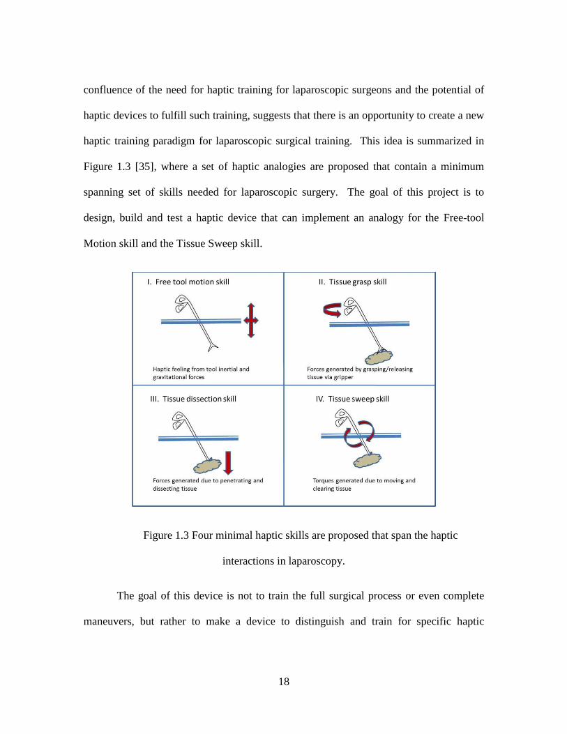
confluence of the need for haptic training for laparoscopic surgeons and the potential of
haptic devices to fulfill such training, suggests that there is an opportunity to create a new
haptic training paradigm for laparoscopic surgical training. This idea is summarized in
Figure 1.3 [35], where a set of haptic analogies are proposed that contain a minimum
spanning set of skills needed for laparoscopic surgery. The goal of this project is to
design, build and test a haptic device that can implement an analogy for the Free-tool
Motion skill and the Tissue Sweep skill.
Figure 1.3 Four minimal haptic skills are proposed that span the haptic
interactions in laparoscopy.
The goal of this device is not to train the full surgical process or even complete
maneuvers, but rather to make a device to distinguish and train for specific haptic
19
abilities. With this particular device, we will test two types of tool motion to determine if
we can identify surgeons by their haptic ability. These tool motions, sweep and idle (free-
tool), are chosen because the implementation of the two methods would have shared
hardware and function as a base point to add in the other states of operations described by
Richards et al. We anticipate that these two haptic analogies will be able to differentiate
between novices and expert surgeons. Furthermore, this device will fill a niche as an
inexpensive trainer in the area of force application and force sensitivity. Current haptic
surgical trainers come with a hefty price tag and are thus hindered in their industry-wide
acceptance. By creating a device that can test the haptic ability of surgeons that is
affordable to the community at large, force application tasks could be tested for, ensuring
surgeons are capable of correctly applying forces in the operating room.
20
CHAPTER 2
DESIGN AND IMPLEMENTATION OF THE HAPTIC MECHANISMS
2.1 Requirements
The requirements on this novel haptic device derive from the haptic analogies that
are going to be implemented. Of the five motions covered in the work from Richards et
al. [46], this device is going to implement the free-tool and sweeping analogies. An
efficient device design will require identifying the common elements of both analogies,
the unique requirements of each analogy, and also the existing approaches and equipment
available.
2.1.1 Sweep Analogy
The origin of the sweep analogy, specifically the lateral movement of the tool
against internal tissues, is illustrated in Figure 2.1, where the surgeon is manipulating
organs and tissues within the body. The laparoscopic tool acts as a lever with a variable
fulcrum determined by the trocar and insertion length. This scenario is modeled as
having a mass-spring-damper system attached to the tip of the tool, as seen in Figure 2.2.
As discussed in the introduction, the goal of this analogy is to produce the salient forces
and torques felt by the surgeon during this type of surgical maneuver. The goal is not to
accurately reproduce a specific tissue, which would obviously demand a much more
sophisticated model.
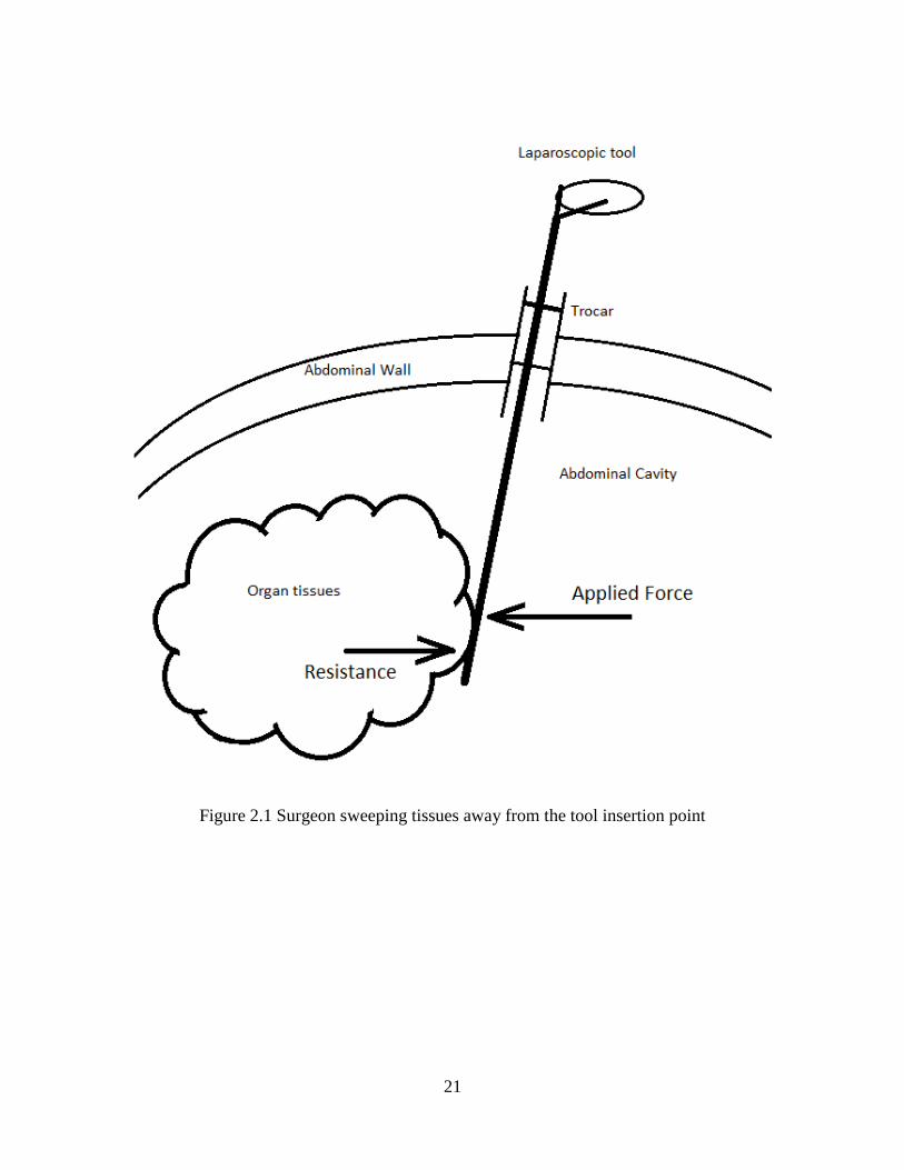
21
Figure 2.1 Surgeon sweeping tissues away from the tool insertion point
22
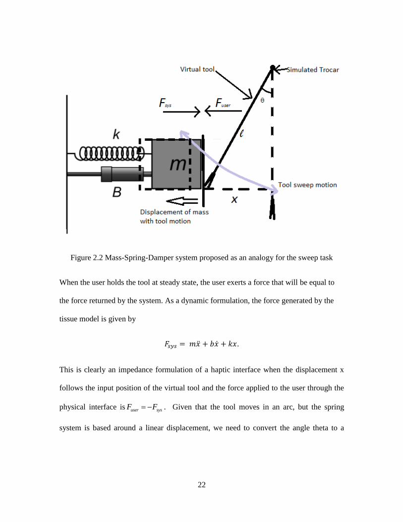
Figure 2.2 Mass-Spring-Damper system proposed as an analogy for the sweep task
When the user holds the tool at steady state, the user exerts a force that will be equal to
the force returned by the system. As a dynamic formulation, the force generated by the
tissue model is given by
.
This is clearly an impedance formulation of a haptic interface when the displacement x
follows the input position of the virtual tool and the force applied to the user through the
physical interface is user sysF F . Given that the tool moves in an arc, but the spring
system is based around a linear displacement, we need to convert the angle theta to a

23
distance x. Using some simple trigonometry, it can be seen that x is related to by the
equation
.
A desired feature of the sweep analogy is that the user can change the geometry of
the analogy by changing the insertion length. This relationship between x and requires
measurement of the length of the tool past the motor pivot point, l. The specific approach
to measuring l if a real laparoscopic tool is used in the user interface is a significant
challenge that will be discussed later. In steady state, where the user is not moving the
tool but rather holding it in position, the equation simplifies to
.
With this, it is evident that user applied force being derived purely from position
measurements, however, the dynamic model will require velocity and acceleration
information.
2.1.2 Free-Tool Analogy
The free-tool motion concept arises from the surgical task of manipulating the
laparoscopic tool within the workspace, inside the human body cavities, without contact
with organs or tissues. There are a number of different laparoscopic tools with different
diameter shafts, end effectors, and handle mechanisms. These tools may be freely moved
while grasping excised tissue. The free-tool analogy should capture the haptic modalities
of this maneuver needed to test and teach free-tool motion skills. Along with the sweep
24
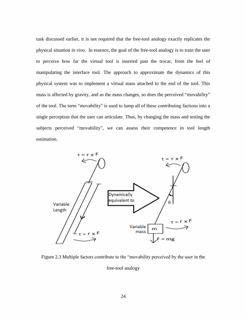
task discussed earlier, it is not required that the free-tool analogy exactly replicates the
physical situation in vivo. In essence, the goal of the free-tool analogy is to train the user
to perceive how far the virtual tool is inserted past the trocar, from the feel of
manipulating the interface tool. The approach to approximate the dynamics of this
physical system was to implement a virtual mass attached to the end of the tool. This
mass is affected by gravity, and as the mass changes, so does the perceived “movability”
of the tool. The term “movability” is used to lump all of these contributing factions into a
single perception that the user can articulate. Thus, by changing the mass and testing the
subjects perceived “movability”, we can assess their competence in tool length
estimation.
Figure 2.3 Multiple factors contribute to the “movability perceived by the user in the
free-tool analogy
25
The static force model of the simplified analogy are given by sinmgr ,
where m is the variable mass that changed between tools, g is the acceleration due to
gravity, is the angle of the tool past the vertical, and is the torque from the virtual
model. The insertion length needs to be measured as the analogy is simulated.
Measurement of the insertion length will be addressed later.
2.1.3 Common Properties
When considering the requirements of a device to fill these analogies, the first
design consideration is the number of degrees-of-freedom our device needs to have. From
this, we notice that we need only one actuated degree-of-freedom, a rotation in the plane
perpendicular to the user. Considering only a single axis of rotation is desired, a single
motor will be sufficient to actuate this degree-of-freedom.
2.1.4 Real-time control hardware
From the broad perspective of controlling a haptic device, the haptic system can
be considered as a robot. Hardware and software tools for robot control prototyping are
widely used. The haptic system can then be considered as the interaction between the real
world robotic device and a virtual world. The user input needs to influence a virtual
system, and this virtual system has to take said input, manipulate the virtual environment,
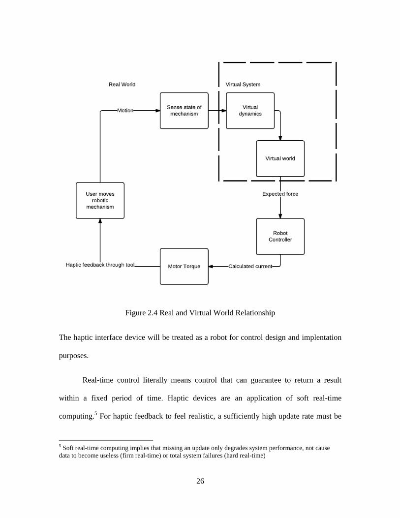
and return the updated virtual world interaction forces. The diagram in Figure 2.4
illustrates the interconnections of the user, virtual world, and interface device.
26
Figure 2.4 Real and Virtual World Relationship
The haptic interface device will be treated as a robot for control design and implentation
purposes.
Real-time control literally means control that can guarantee to return a result
within a fixed period of time. Haptic devices are an application of soft real-time
computing.5 For haptic feedback to feel realistic, a sufficiently high update rate must be
5 Soft real-time computing implies that missing an update only degrades system performance, not cause
data to become useless (firm real-time) or total system failures (hard real-time)
27
maintained. Failure to maintain a high and consistent update rate will weaken the illusion
of the rendered environment. Currently, 1 kilohertz (kHz) is the generally accepted
update rate necessary for rendering solid objects. However, for textures, a faster update
rate, on the order of 5-10 kHz is desirable for perceptually stable rendering [47]. With
this requirement in mind, a target update rate of 10 kHz is chosen. There is a tradeoff in
haptic rendering between model complexity and maximum attainable update rate. With
the exception of the length sensor, the remainder of the simulation model is sufficiently
simple to be implemented at the desired 10 kHz. For this reason, the length sensor will be
implemented in a separate program.
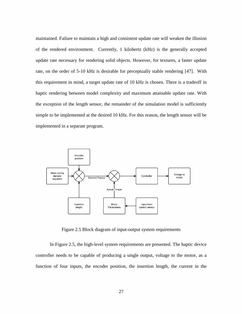
Figure 2.5 Block diagram of input-output system requirements
In Figure 2.5, the high-level system requirements are presented. The haptic device
controller needs to be capable of producing a single output, voltage to the motor, as a
function of four inputs, the encoder position, the insertion length, the current in the
28
motor, and the model equation. The system also has to be capable of processing the input
information to make calculations to determine the desired output. To do this, a system
capable of multiple inputs and real-time operation is needed.
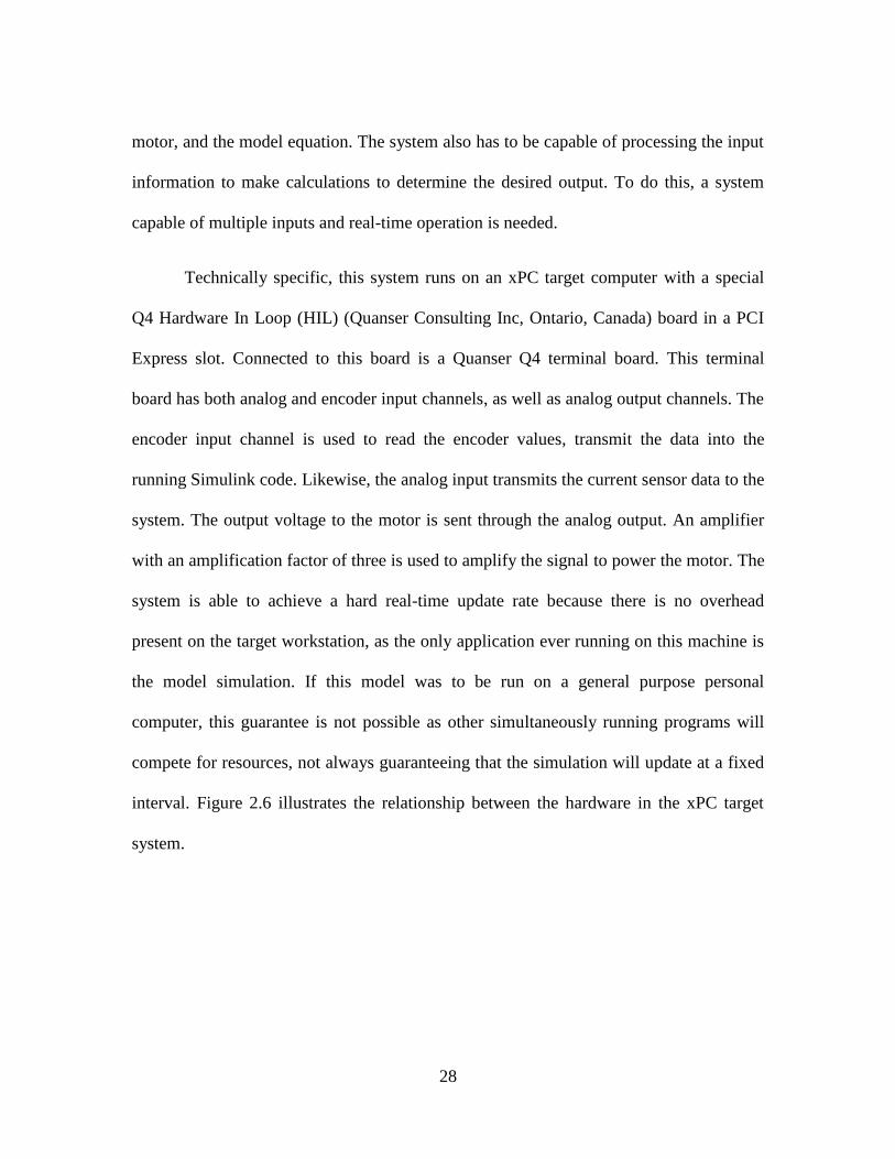
Technically specific, this system runs on an xPC target computer with a special
Q4 Hardware In Loop (HIL) (Quanser Consulting Inc, Ontario, Canada) board in a PCI
Express slot. Connected to this board is a Quanser Q4 terminal board. This terminal
board has both analog and encoder input channels, as well as analog output channels. The
encoder input channel is used to read the encoder values, transmit the data into the
running Simulink code. Likewise, the analog input transmits the current sensor data to the
system. The output voltage to the motor is sent through the analog output. An amplifier
with an amplification factor of three is used to amplify the signal to power the motor. The
system is able to achieve a hard real-time update rate because there is no overhead
present on the target workstation, as the only application ever running on this machine is
the model simulation. If this model was to be run on a general purpose personal
computer, this guarantee is not possible as other simultaneously running programs will
compete for resources, not always guaranteeing that the simulation will update at a fixed
interval. Figure 2.6 illustrates the relationship between the hardware in the xPC target
system.
29
Figure 2.6 Model of xPC target setup
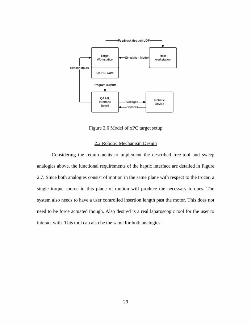
2.2 Robotic Mechanism Design
Considering the requirements to implement the described free-tool and sweep
analogies above, the functional requirements of the haptic interface are detailed in Figure
2.7. Since both analogies consist of motion in the same plane with respect to the trocar, a
single torque source in this plane of motion will produce the necessary torques. The
system also needs to have a user controlled insertion length past the motor. This does not
need to be force actuated though. Also desired is a real laparoscopic tool for the user to
interact with. This tool can also be the same for both analogies.
30
Figure 2.7 Schematic of the Functional Requirement of the Free-Tool and Sweep
Analogies. The commonality of these analogies allows a single realization where a real
laparoscopic tool is actuated by an electric motor.
The motor is the primary component of the haptic device and needs to be
considered carefully to ensure that it will perform adequately. More importantly, the
range of torques that this system will recreate should be sufficient to produce the analogy
of the torques experienced through actual laparoscopic procedures.
2.2.1 Establishment of motor specifications
In vivo measurements of laparoscopy were used to determine the range of motion
and the peak torque needed in the haptic analogies. First, in establishing a range of
motion necessary for the haptic device, the range of motion in a real procedure is
31
considered. According to the work from Picod et al, a 60 degree cone was sufficient to
perform most standard sweep and free-tool manipulations [48]. Thus, a range of 30
degrees from center in each direction would be sufficient for the proposed haptic device.
For the necessary torque to be produced, we see that in the same work from Picod and co-
researchers that the measured torques for the interaction between the instrument and the
organ ranges from 0 to 100 millinewton meters (mNm) [48]. The device used in these in
vivo measurements was able to record lateral forces at the tool tip ranging from 0.1 to 10
Newtons, using a standard laparoscopic device outfitted with force sensors. This means
that the tool is at least 1 cm past the trocar during measurements. These measures of tool-
tip forces are a reference range for the forces and torques that the haptic device should
reproduce.
Given the above requirements, and allowing for significant range to overshoot the
targets, the motor should be capable of producing at least 150 mNm of torque over a 90
degree cone. Both analogies reduce the actual motion from a two-dimensional cone to a
one-dimensional planar rotation. Furthermore, an encoder with at least 1000 counts per
revolution to provide a 0.36 degree resolution will also be necessary to ensure that
closed-loop position control will have accurate feedback.
2.2.2 Evaluation of the selected motor
The Tohoku Ricoh DC motor (P/N 52155301) with an optical encoder was
selected for the initial prototype. The motor advertises a 49.4 millinewton-meter per
ampere (mNm/A) torque constant. For a laparoscopic tool, with an insertion length at a
32
minimum 1 cm at a peak current of 4 Amperes, this motor can simulate a tip force of
19.75 N. As this is an important part of the robotic mechanism, a series of lab benchmark
tests were done to characterize the motor.
Looking at how this device will be realized, we see that we will need to control
the torque on the motor. To control the motor torque, we need to control the current sent
to the motor. Thus, we need to be able to measure the current sent to the motor, and send
a voltage to the motor. To accomplish this, we need a method of sending sufficient
voltage to the motor, and a method of measuring the current. Furthermore, an amplifier to
bring the power transmitted from the computer output to a voltage more usable by the
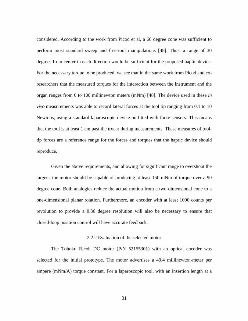
motor would be necessary. The proposed system is shown in Figure 2.8. This will also
have to have a control algorithm, which will be discussed later.
Figure 2.8 Simplified conceptual circuit diagram
As seen in Figure 2.8, the motor was connected to the amplifier and current
sensing circuitry. An arm was connected to the motor shaft and the free end of the arm
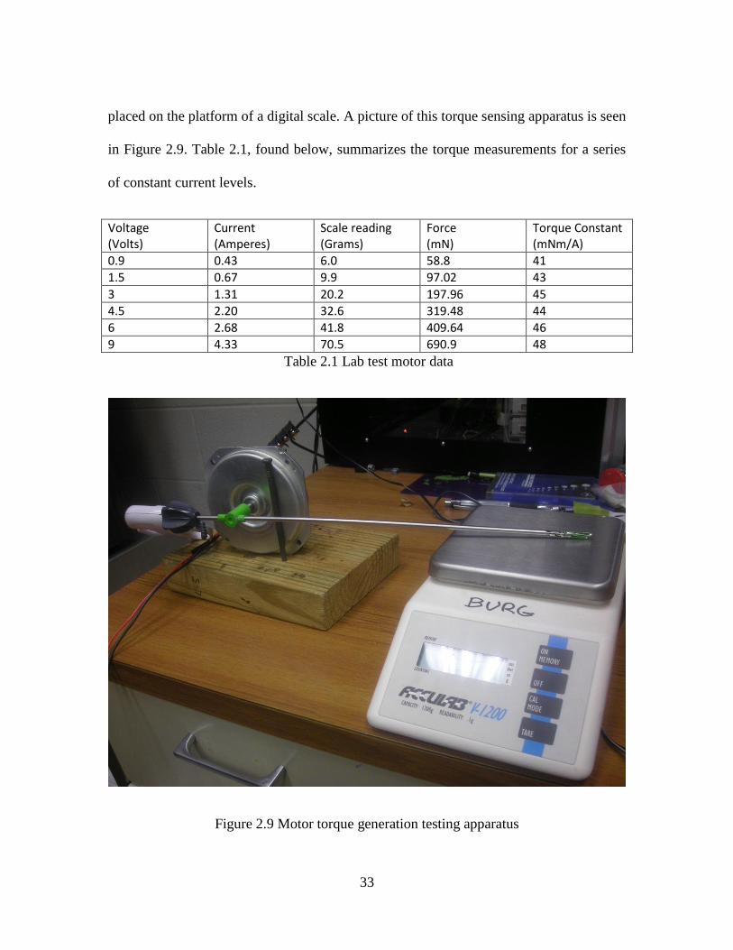
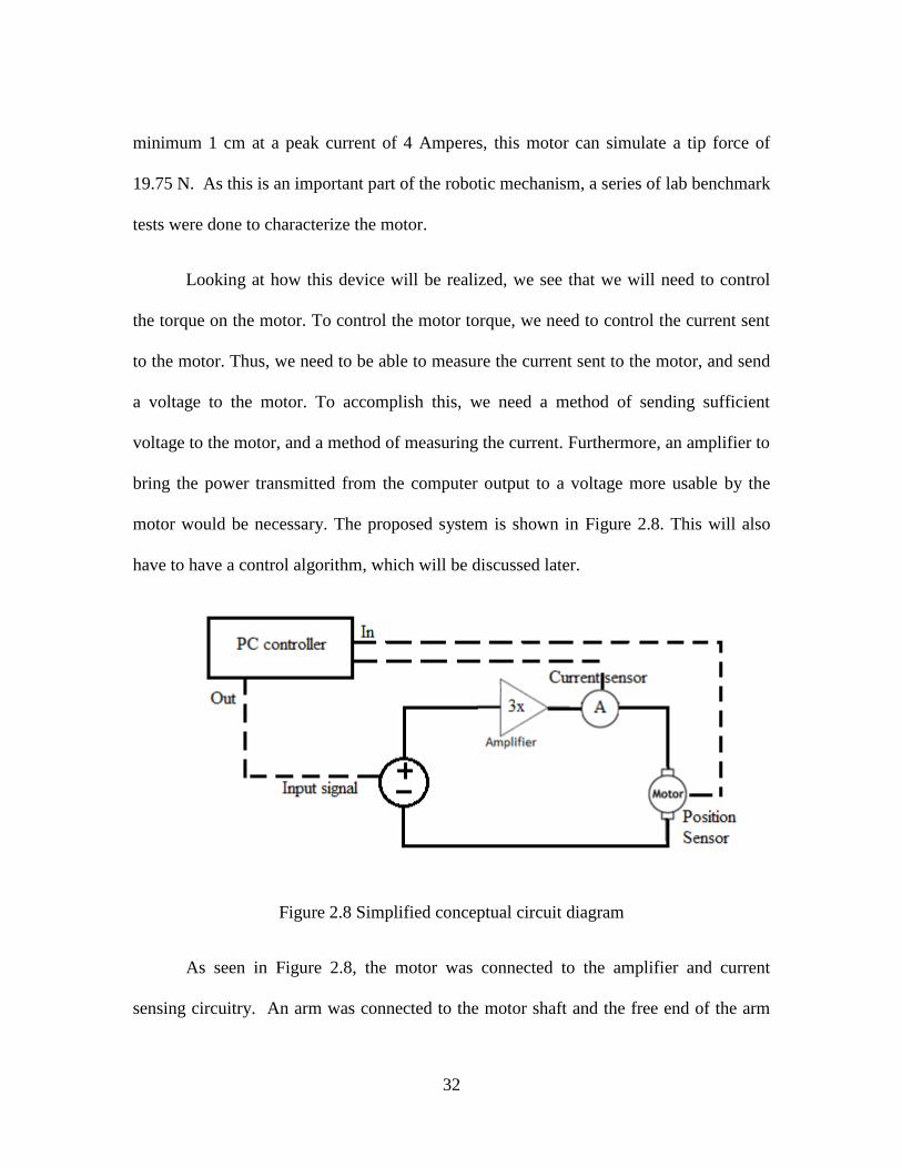
33
placed on the platform of a digital scale. A picture of this torque sensing apparatus is seen
in Figure 2.9. Table 2.1, found below, summarizes the torque measurements for a series
of constant current levels.
Voltage (Volts)
Current (Amperes)
Scale reading (Grams)
Force (mN)
Torque Constant (mNm/A)
0.9 0.43 6.0 58.8 41
1.5 0.67 9.9 97.02 43
3 1.31 20.2 197.96 45
4.5 2.20 32.6 319.48 44
6 2.68 41.8 409.64 46
9 4.33 70.5 690.9 48
Table 2.1 Lab test motor data
Figure 2.9 Motor torque generation testing apparatus

34
From Table 2.1, we can see that the calculated torque constant approaches the
advertised torque constant for higher currents. The proposed device will require
consistent, but not necessarily accurate torque production, thus a median value of 45
mNm/A for a torque constant will be used in simulations. Note that the table can be used
to compensate for the nonlinearity of the torque constant if more accuracy is needed.
2.2.3 Current Control Loop
Since the torque of the motor is dependent on the current, the controller will be
designed to control the current in order to implement torque control. A standard
Proportional-Integral (PI) controller was selected. The Simulink simulations that are
converted and executed on the xPC target machine use this controller shown in Figure
2.10. In Figure 2.10 the block diagram has been augmented to assist in understanding
how the system is interacting with the real world, the physical motor system has been
superimposed onto the model, showing where the physical motor connects to the
controller. The torque constant found earlier is used in the “current converter” block. The
motor can be simulated to prove that the controller works to produce current control for
various input signals.
35
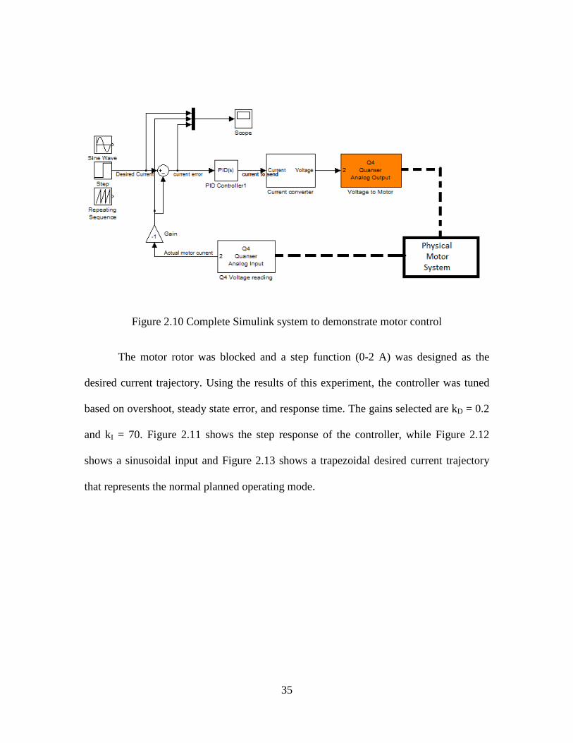
Figure 2.10 Complete Simulink system to demonstrate motor control
The motor rotor was blocked and a step function (0-2 A) was designed as the
desired current trajectory. Using the results of this experiment, the controller was tuned
based on overshoot, steady state error, and response time. The gains selected are kD = 0.2
and kI = 70. Figure 2.11 shows the step response of the controller, while Figure 2.12
shows a sinusoidal input and Figure 2.13 shows a trapezoidal desired current trajectory
that represents the normal planned operating mode.
36
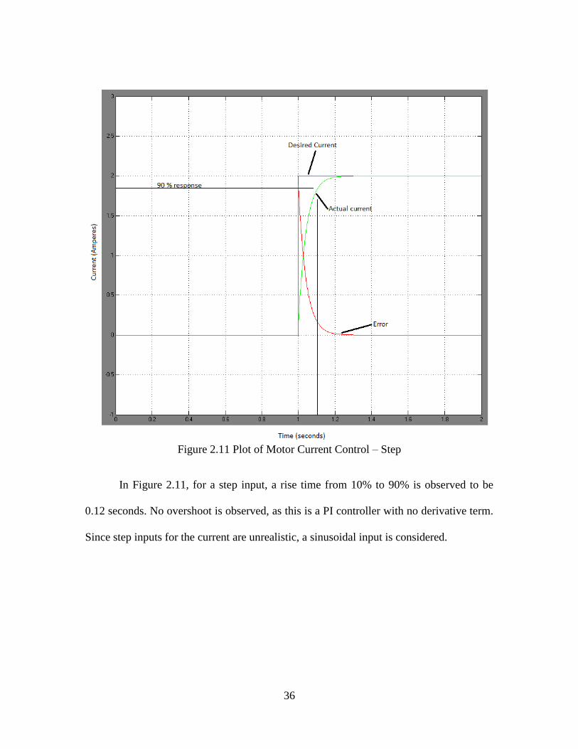
Figure 2.11 Plot of Motor Current Control – Step
In Figure 2.11, for a step input, a rise time from 10% to 90% is observed to be
0.12 seconds. No overshoot is observed, as this is a PI controller with no derivative term.
Since step inputs for the current are unrealistic, a sinusoidal input is considered.
37
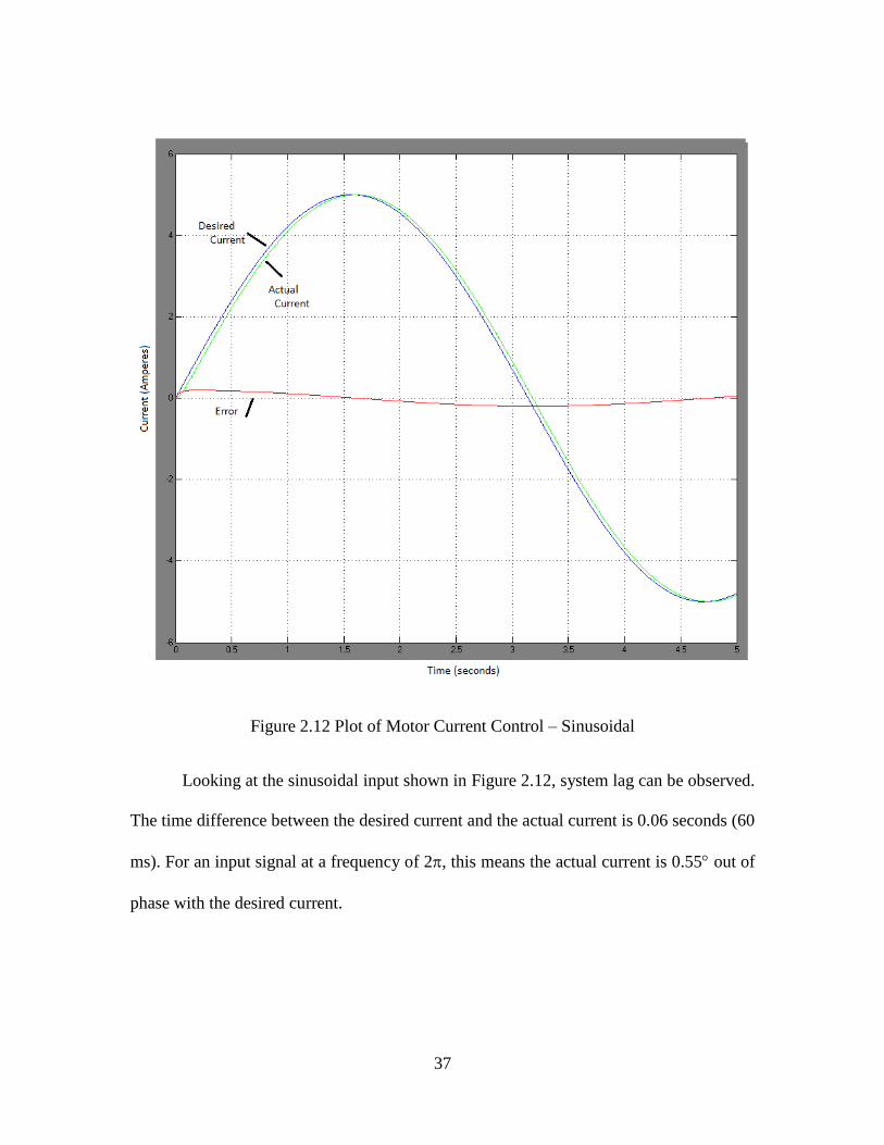
Figure 2.12 Plot of Motor Current Control – Sinusoidal
Looking at the sinusoidal input shown in Figure 2.12, system lag can be observed.
The time difference between the desired current and the actual current is 0.06 seconds (60
ms). For an input signal at a frequency of 2, this means the actual current is 0.55 out of
phase with the desired current.
38
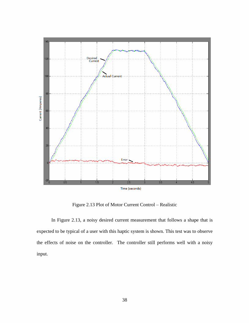
Figure 2.13 Plot of Motor Current Control – Realistic
In Figure 2.13, a noisy desired current measurement that follows a shape that is
expected to be typical of a user with this haptic system is shown. This test was to observe
the effects of noise on the controller. The controller still performs well with a noisy
input.

39
2.3 Support Structure
The motor is required to generate a torque based upon the virtual interactions. The
equation for torque at the tool handle is , where r is the distance from the
motor shaft to the handle, and F is the force at the tool handle. There is a need to be able
to sense the distance from the shaft of the motor to the tip of the tool being used, where
interaction forces are considered to be applied. The entire tool is 40 cm long, including
the handle. The shaft of the tool is 34 cm long. This is the tool seen in Figure 2.7. The
user-movable distance in that figure is 25 cm. From an overhead view, Figure 2.14
illustrates the dimensional requirements of the system. As mentioned in Section 1.3.3, the
device needs to occlude the device mechanics from the user, thus enclosing the tool is
desirable. The enclosure dimensions are also marked in Figure 2.14.

40
Figure 2.14 Overhead view of the range of tool motion
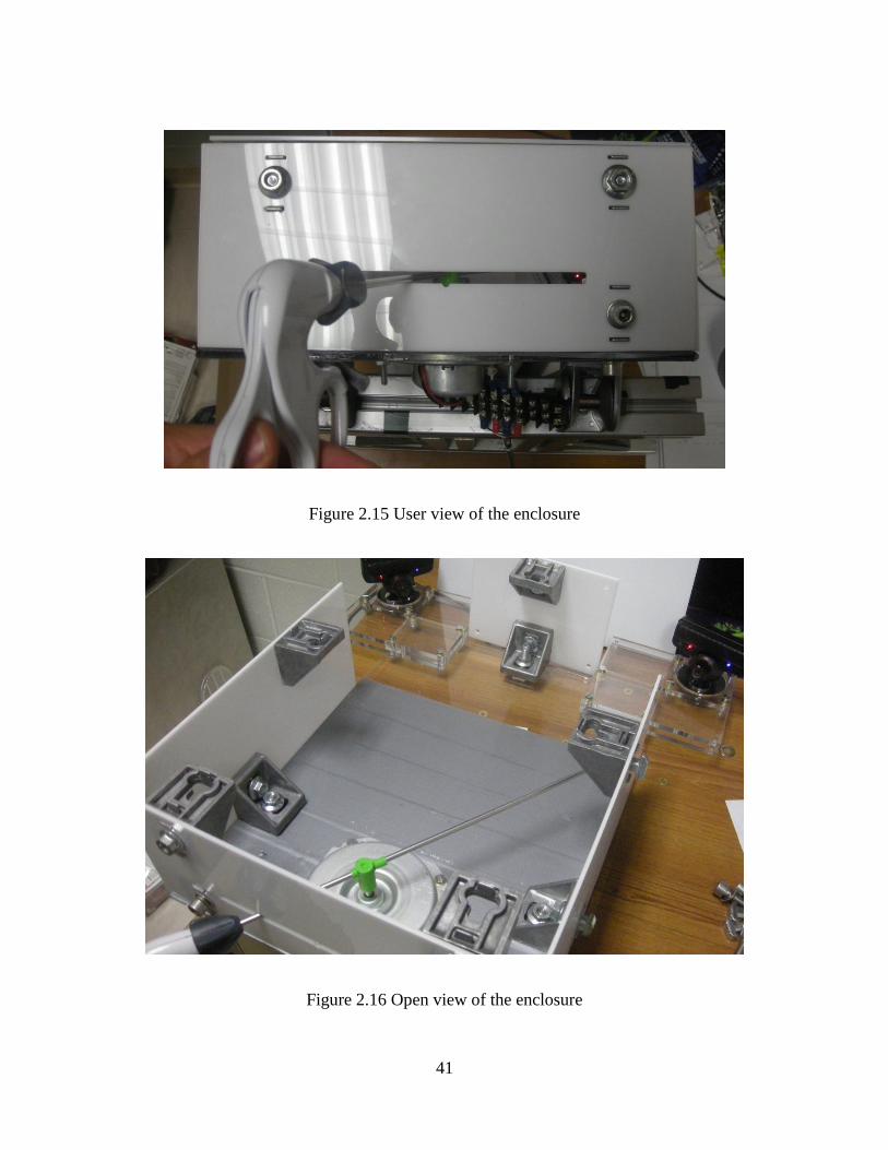
In Figure 2.14, the black outer line marks the size of the enclosure. To create this
custom enclosure, laser cut acrylic plastic parts are secured together with Bosch
aluminum structural framing brackets. Figure 2.15 shows the device from the perspective
of a user, and Figures 2.16 and 2.17 show the insides of the enclosure and the complete
enclosure respectively.
41
Figure 2.15 User view of the enclosure
Figure 2.16 Open view of the enclosure
42
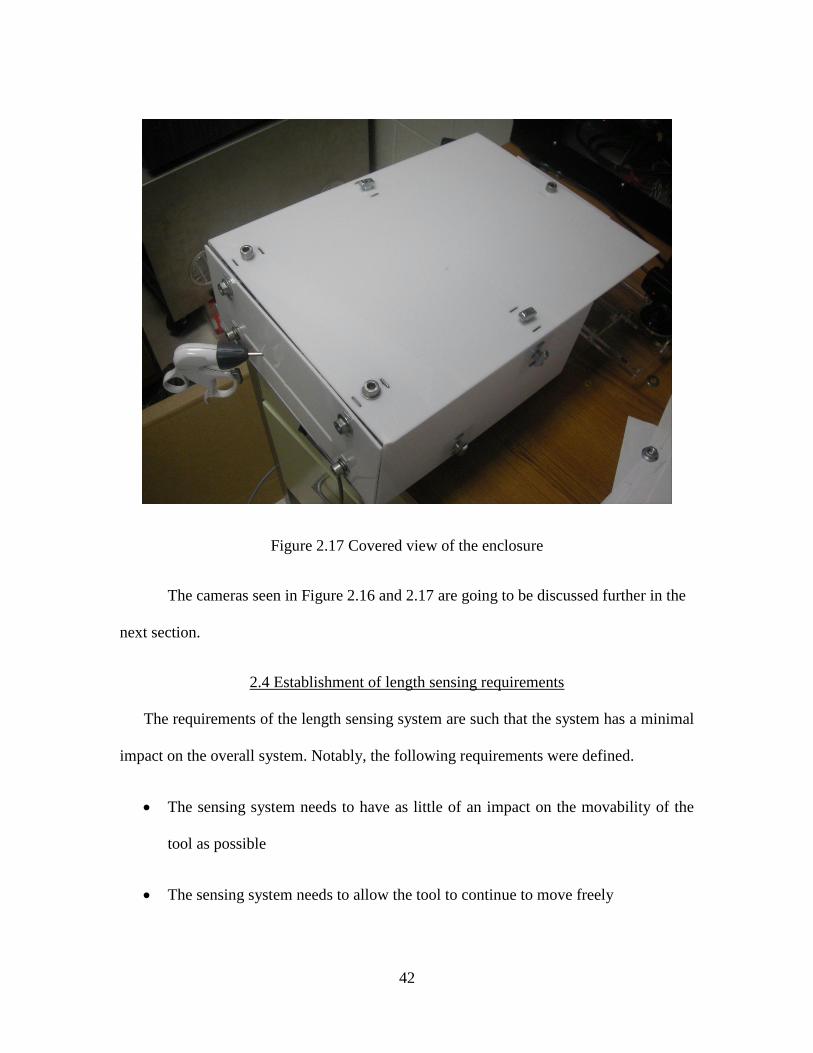
Figure 2.17 Covered view of the enclosure
The cameras seen in Figure 2.16 and 2.17 are going to be discussed further in the
next section.
2.4 Establishment of length sensing requirements
The requirements of the length sensing system are such that the system has a minimal
impact on the overall system. Notably, the following requirements were defined.
The sensing system needs to have as little of an impact on the movability of the
tool as possible
The sensing system needs to allow the tool to continue to move freely
43
The sensing system needs to be robust
The sensing system needs to update at a rate faster than controlled human
movement speeds. An update rate of about 10 Hertz will be acceptable [13].
The sensing system requires a positional accuracy of less than 2 cm.
With this set of requirements, several sensing systems were considered.
2.4.1 Selection of sensing technique
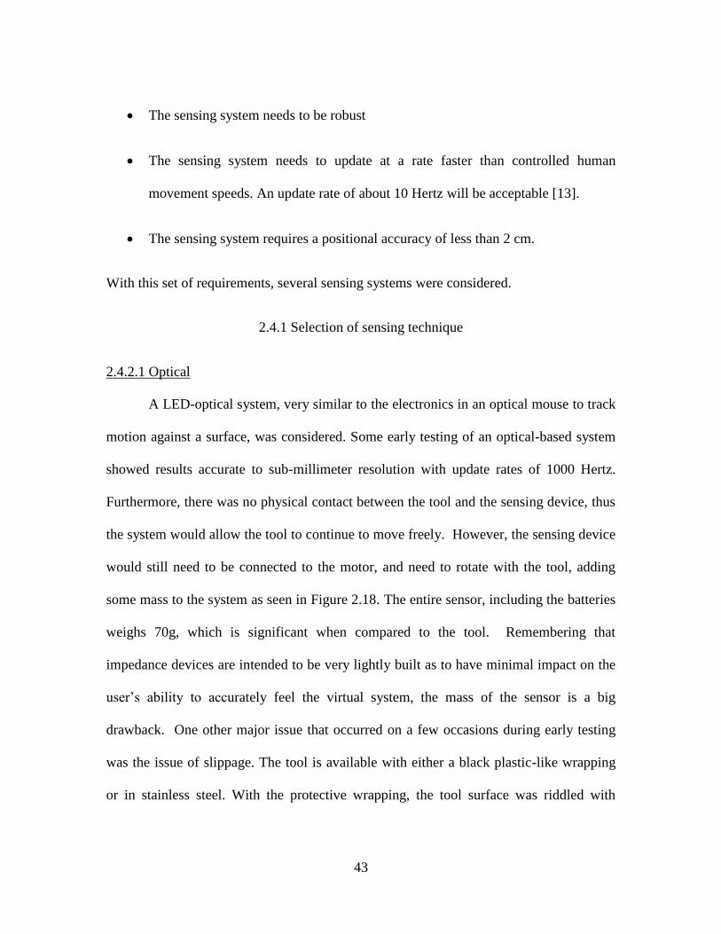
2.4.2.1 Optical
A LED-optical system, very similar to the electronics in an optical mouse to track
motion against a surface, was considered. Some early testing of an optical-based system
showed results accurate to sub-millimeter resolution with update rates of 1000 Hertz.
Furthermore, there was no physical contact between the tool and the sensing device, thus
the system would allow the tool to continue to move freely. However, the sensing device
would still need to be connected to the motor, and need to rotate with the tool, adding
some mass to the system as seen in Figure 2.18. The entire sensor, including the batteries
weighs 70g, which is significant when compared to the tool. Remembering that
impedance devices are intended to be very lightly built as to have minimal impact on the
user’s ability to accurately feel the virtual system, the mass of the sensor is a big
drawback. One other major issue that occurred on a few occasions during early testing
was the issue of slippage. The tool is available with either a black plastic-like wrapping
or in stainless steel. With the protective wrapping, the tool surface was riddled with
44
bumps and ridges that caused slip issues with the sensor. With the wrapping removed,
the surface has a reflection that on some of the trials caused issues with the tracking as
well. With no reliable method of knowing that a slip occurred, the robustness of an
optical sensing system is questionable.
Figure 2.18 Optical sensor setup
45
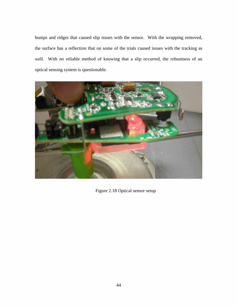
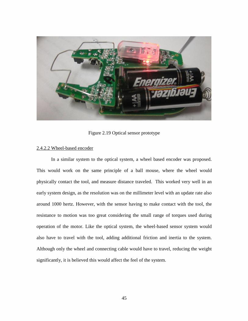
Figure 2.19 Optical sensor prototype
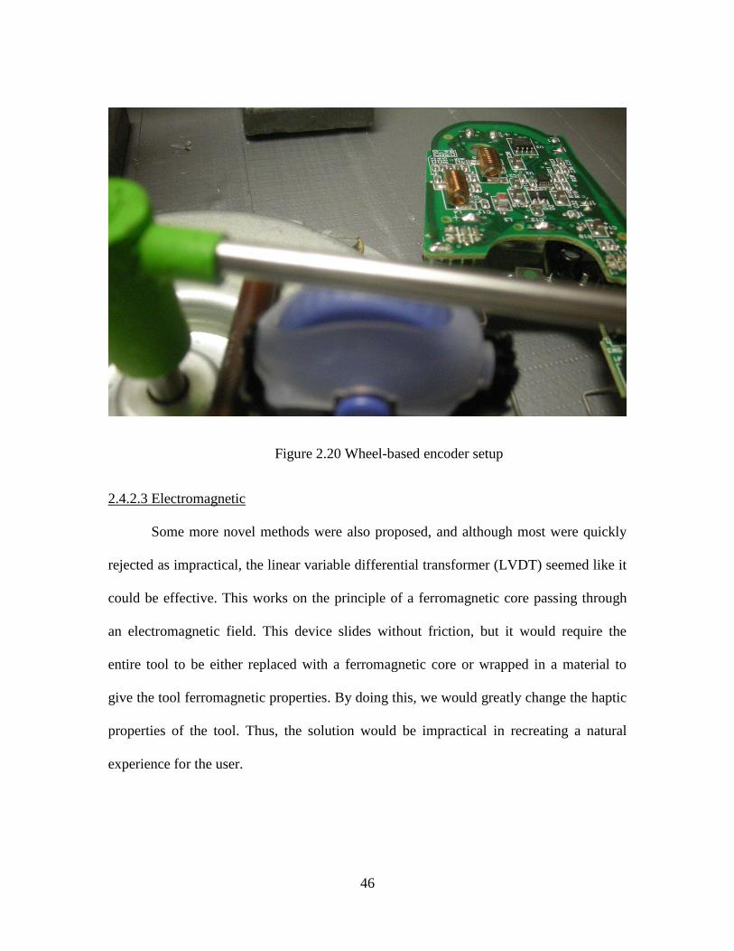
2.4.2.2 Wheel-based encoder
In a similar system to the optical system, a wheel based encoder was proposed.
This would work on the same principle of a ball mouse, where the wheel would
physically contact the tool, and measure distance traveled. This worked very well in an
early system design, as the resolution was on the millimeter level with an update rate also
around 1000 hertz. However, with the sensor having to make contact with the tool, the
resistance to motion was too great considering the small range of torques used during
operation of the motor. Like the optical system, the wheel-based sensor system would
also have to travel with the tool, adding additional friction and inertia to the system.
Although only the wheel and connecting cable would have to travel, reducing the weight
significantly, it is believed this would affect the feel of the system.
46
Figure 2.20 Wheel-based encoder setup
2.4.2.3 Electromagnetic
Some more novel methods were also proposed, and although most were quickly
rejected as impractical, the linear variable differential transformer (LVDT) seemed like it
could be effective. This works on the principle of a ferromagnetic core passing through
an electromagnetic field. This device slides without friction, but it would require the
entire tool to be either replaced with a ferromagnetic core or wrapped in a material to
give the tool ferromagnetic properties. By doing this, we would greatly change the haptic
properties of the tool. Thus, the solution would be impractical in recreating a natural
experience for the user.
47
2.4.2.4 Visual
Considering the initial requirements did not demand a very high level of accuracy
or update rate, a visual system through a webcam would likely fulfill the demands. A
camera-based system would not have any physical contact with the tool, and considering
that in development talks, an enclosed environment system is a desired end product, a
vision system could provide a very robust solution. With other sensor solutions, errors in
the sensing would be undetectable, but with a camera system, even if an inaccurate
measurement is made at one point, correcting this measurement is possible. Furthermore,
as there is no contact with the tool, this sensing solution would have no effect on the
user’s ability to accurately feel the virtual environment. Thus, the decision to use a visual
system was made.
2.4.2 Camera analysis
For the actual cameras, a pair of PlayStation Eye cameras, which are capable of a
640x480 resolution video at 60 frames per second, was readily available for the
prototype. They are changeable from a 56 degree field of view to a 75 degree field of
view, and are capable of uncompressed video output. Any webcam of sufficient
resolution and frame rate would likely be usable for this application with only minor
placement adjustments for field of view accommodations. In this application, the
horizontal field of view is of importance, which for the 75 degree setting is only 67
degrees. Thus, for calculations in location and placement of the camera and the
associated field of view, a 67 degree angle will be considered.
48
First and foremost, the camera system must be able to locate the motor point and
locate the tool tip. This is vital information to the remaining parts of the length detection
system, and if the points cannot be detected, the vision algorithms will fail. Because this
is designed to be an enclosed system, simpler techniques of point identification and
tracking can be used. Notably, as the system is enclosed, color information, and thus
color-based thresholding, can be used to identify and locate the tool and motor.
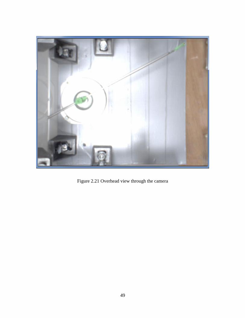
To interface with the cameras, OpenCV was chosen for its industry-wide
acceptance, freely open to modify for specific application needs, and a BSD license, as
well as the computational efficiency [49]. In finding the tool tip, first the frame is
captured, and then in a pixel-based operation, all areas in the image of sufficient levels in
the green channel, and also with a green channel significantly higher than the other
channels, are highlighted. A view of this from an overhead camera position is shown in
Figure 2.21.
49
Figure 2.21 Overhead view through the camera
50
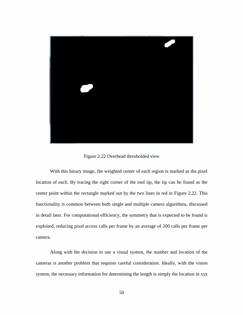
Figure 2.22 Overhead thresholded view
With this binary image, the weighted center of each region is marked as the pixel
location of each. By tracing the right corner of the tool tip, the tip can be found as the
center point within the rectangle marked out by the two lines in red in Figure 2.22. This
functionality is common between both single and multiple camera algorithms, discussed
in detail later. For computational efficiency, the symmetry that is expected to be found is
exploited, reducing pixel access calls per frame by an average of 200 calls per frame per
camera.
Along with the decision to use a visual system, the number and location of the
cameras is another problem that requires careful consideration. Ideally, with the vision
system, the necessary information for determining the length is simply the location in xyz
51
space of the motor connection and the xyz coordinate of the tip of the tool. With the two
coordinates, the length is easy to calculate. However, localizing a point in three full
dimensions is very difficult. We can make one simplifying assumption to our
localization: the tool tip is only mobile in a plane. This assumption is reasonably valid, as
the out of plane motion available is less than a quarter of an inch (0.25”), and the in-plane
motion is on the order of five to ten inches (5-10”). This slight out of plane motion is well
within our length sensing requirements, as a 0.25” perturbation at 5” past the motor, the
worst case deflection scenario, is only going to change a true measurement by 0.006”.
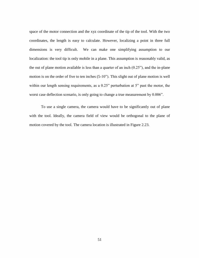
To use a single camera, the camera would have to be significantly out of plane
with the tool. Ideally, the camera field of view would be orthogonal to the plane of
motion covered by the tool. The camera location is illustrated in Figure 2.23.
52
Figure 2.23 Single camera location for full range of motion viewing
With the camera needing to cover a maximum insertion length of 10”, the camera
would need to be located 8” above the plane that the tool moves in, or about 10” above
the motor plane, so that the entire range of motion of the tool is within the viewing range
of the camera. While the concept is explained in some detail, the goal of isolating visual
feedback from the user would be less possible with this camera setup as completing an
enclosure around the device would be impractical.
Considering the total size of the device and enclosure, an alternate
implementation where the cameras are not out of plane with the rest of the device is
considered. With availability of cheap and easy to use cameras, using multiple cameras is
not an issue of cost. An unmatched stereo pair setup appears to be the most efficient
53
method of solving the insertion length problem without leaving the plane of motion. The
general idea is demonstrated in the following figures and commentary.
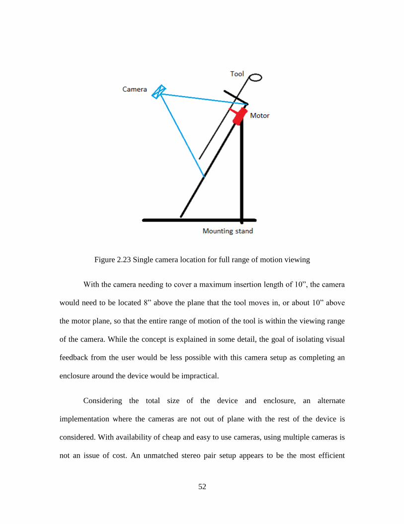
Figure 2.24 An overhead view of an in-plane camera field of view
Using a single camera for in-plane length estimation would be unsuitable. As seen
in Figure 2.24, when the tool tip is in position A or in position B, the view from a single
camera cannot distinguish the insertion length between the two points, despite their
drastic differences, since the tool tip is approaching directly into the lens. In a perfect
system, this would not be an issue as the size of the tool tip in the camera would define
the distance from the camera. However, this measurement would be hypersensitive to
noise, as a few pixels would change length estimates by several inches. Thus, to avoid
this, we consider the tool tip to always be located at a single pixel. Because of this
definition, there is a level of ambiguity between positions A, and B, as well as between C,
D, and E. To the camera, the point determined to be the tool tip is identical, although the
54
insertion lengths are completely different. By placing another camera on the other side of
the device, we can accurately distinguish between these points, as seen in Figure 2.13.
For any point, there can be ambiguity in one camera, but it will always be resolved in the
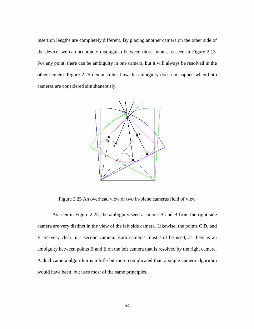
other camera. Figure 2.25 demonstrates how the ambiguity does not happen when both
cameras are considered simultaneously.
Figure 2.25 An overhead view of two in-plane cameras field of view
As seen in Figure 2.25, the ambiguity seen at points A and B from the right side
camera are very distinct in the view of the left side camera. Likewise, the points C,D, and
E are very clear in a second camera. Both cameras must still be used, as there is an
ambiguity between points B and E on the left camera that is resolved by the right camera.
A dual camera algorithm is a little bit more complicated than a single camera algorithm
would have been, but uses most of the same principles.
55
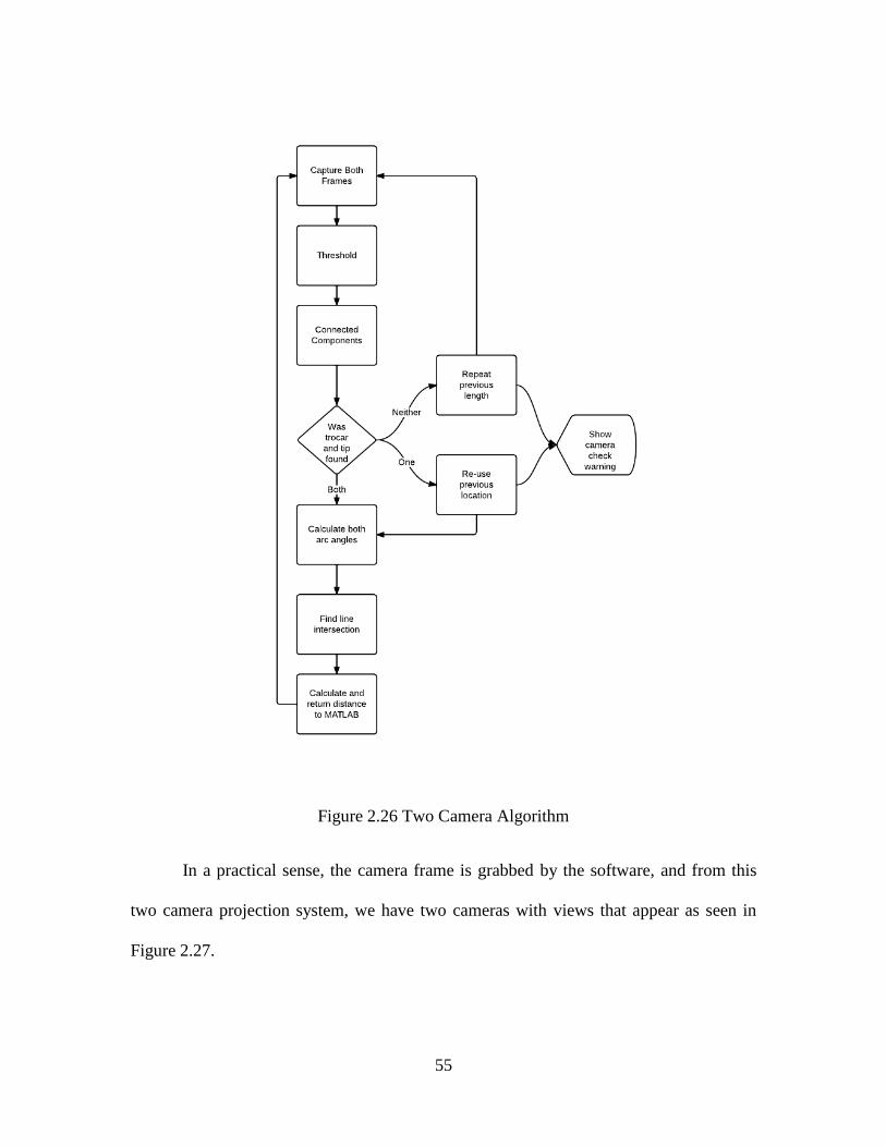
Figure 2.26 Two Camera Algorithm
In a practical sense, the camera frame is grabbed by the software, and from this
two camera projection system, we have two cameras with views that appear as seen in
Figure 2.27.
56
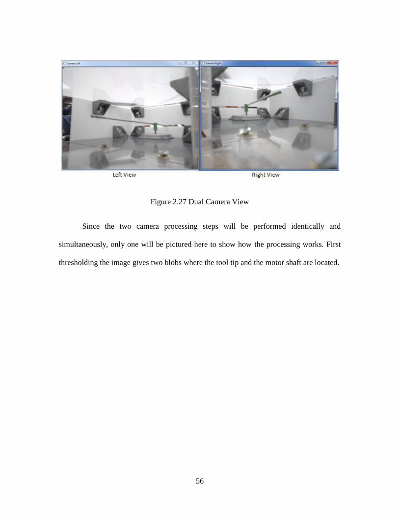
Figure 2.27 Dual Camera View
Since the two camera processing steps will be performed identically and
simultaneously, only one will be pictured here to show how the processing works. First
thresholding the image gives two blobs where the tool tip and the motor shaft are located.
57
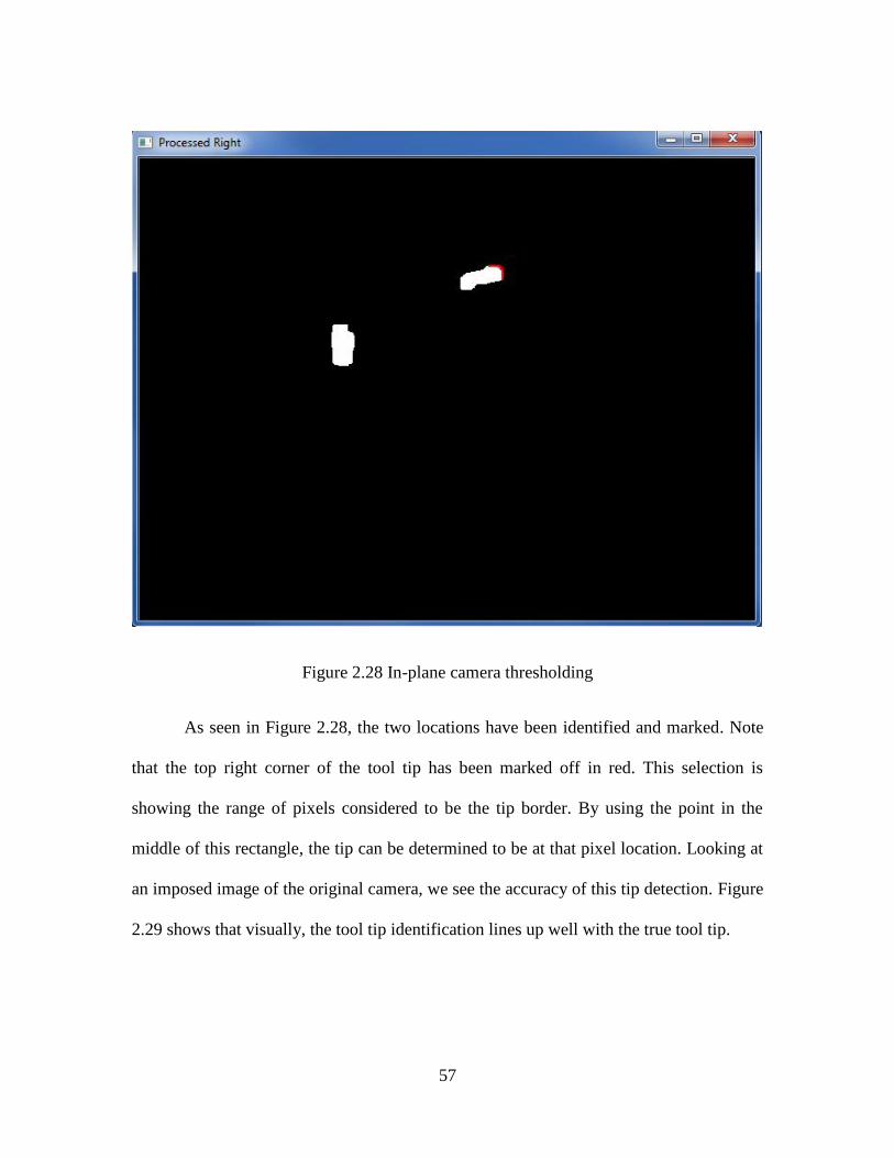
Figure 2.28 In-plane camera thresholding
As seen in Figure 2.28, the two locations have been identified and marked. Note
that the top right corner of the tool tip has been marked off in red. This selection is
showing the range of pixels considered to be the tip border. By using the point in the
middle of this rectangle, the tip can be determined to be at that pixel location. Looking at
an imposed image of the original camera, we see the accuracy of this tip detection. Figure
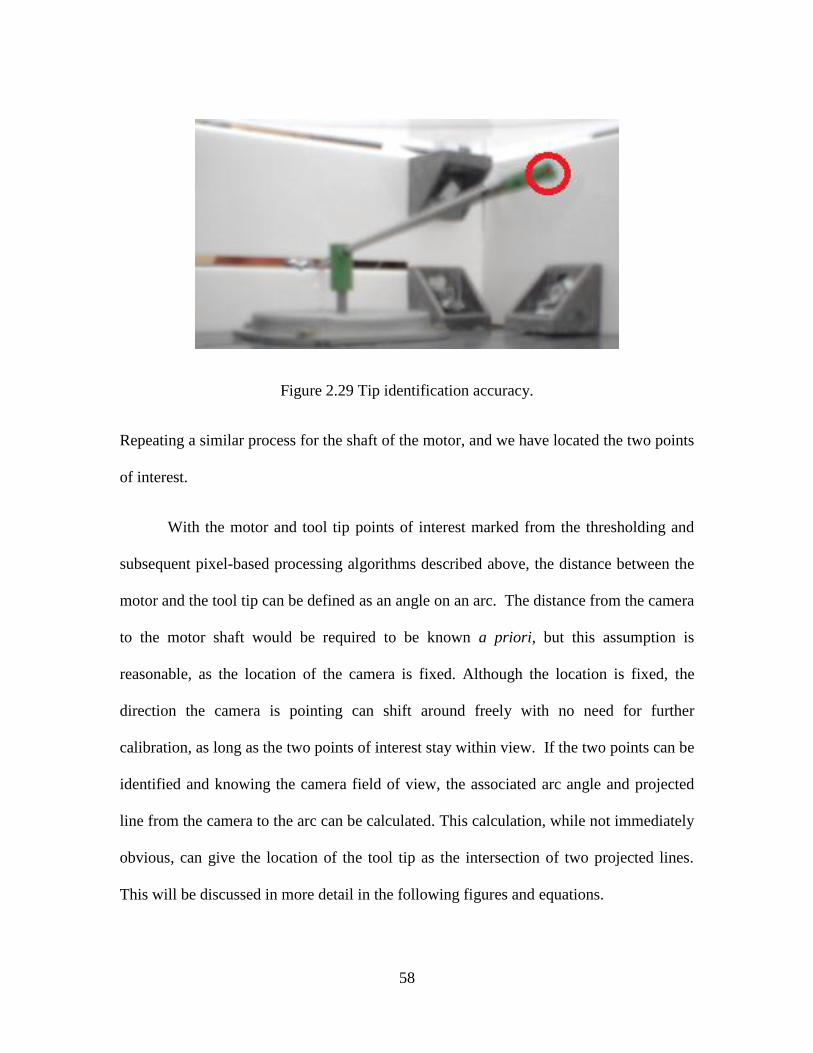
2.29 shows that visually, the tool tip identification lines up well with the true tool tip.
58
Figure 2.29 Tip identification accuracy.
Repeating a similar process for the shaft of the motor, and we have located the two points
of interest.
With the motor and tool tip points of interest marked from the thresholding and
subsequent pixel-based processing algorithms described above, the distance between the
motor and the tool tip can be defined as an angle on an arc. The distance from the camera
to the motor shaft would be required to be known a priori, but this assumption is
reasonable, as the location of the camera is fixed. Although the location is fixed, the
direction the camera is pointing can shift around freely with no need for further
calibration, as long as the two points of interest stay within view. If the two points can be
identified and knowing the camera field of view, the associated arc angle and projected
line from the camera to the arc can be calculated. This calculation, while not immediately
obvious, can give the location of the tool tip as the intersection of two projected lines.
This will be discussed in more detail in the following figures and equations.
59
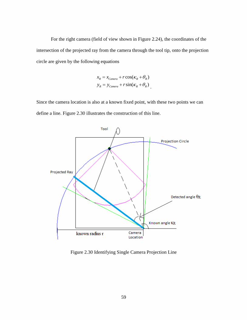
For the right camera (field of view shown in Figure 2.24), the coordinates of the
intersection of the projected ray from the camera through the tool tip, onto the projection
circle are given by the following equations
cos( )
sin( )
R Camera R R
R Camera R R
x x r
y y r
.
Since the camera location is also at a known fixed point, with these two points we can
define a line. Figure 2.30 illustrates the construction of this line.
Figure 2.30 Identifying Single Camera Projection Line
60
Doing this again for the second camera, with a different location and L gives us
a second line. The tool tip is located at the intersection of these two lines, as seen in
Figure 2.31.
Figure 2.31 Identifying Intersection of Projection Lines
To find the intersection of two lines given the four points, where the points (xL1,
yL1) (xL2, yL2) are the camera and tip location in the left frame, and (xR1, yR1) and (xR2,
yR2) are the right frame coordinates, the following algorithm is employed
1 2 1 2 1 2 1 2
1 2 2 1 1 2 2 1
( )( ) ( )( )
( )( ) ( )( )
R R L R R R L R
R R L L R R L L
x x y y y y x xu
y y x x x x y y
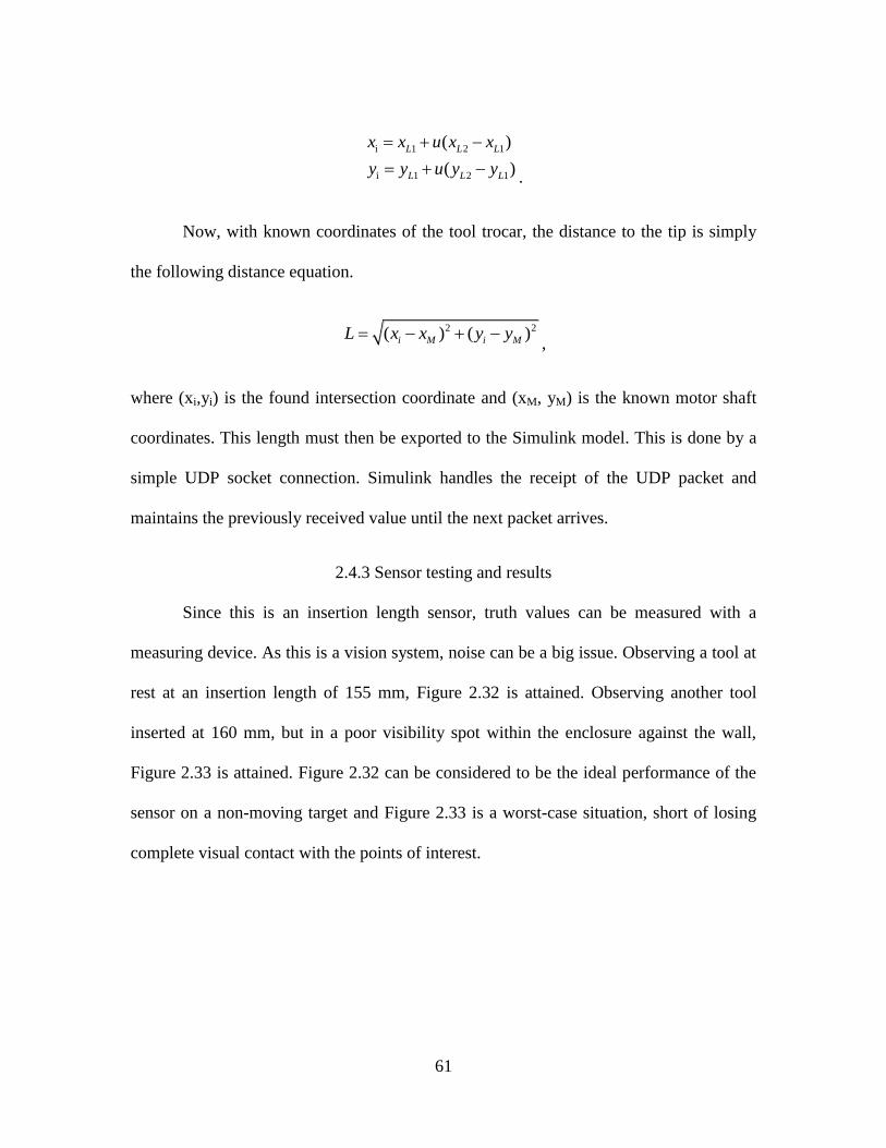
61
i 1 2 1
i 1 2 1
( )
( )
L L L
L L L
x x u x x
y y u y y
.
Now, with known coordinates of the tool trocar, the distance to the tip is simply
the following distance equation.
2 2( ) ( )i M i ML x x y y ,
where (xi,yi) is the found intersection coordinate and (xM, yM) is the known motor shaft
coordinates. This length must then be exported to the Simulink model. This is done by a
simple UDP socket connection. Simulink handles the receipt of the UDP packet and
maintains the previously received value until the next packet arrives.
2.4.3 Sensor testing and results
Since this is an insertion length sensor, truth values can be measured with a
measuring device. As this is a vision system, noise can be a big issue. Observing a tool at
rest at an insertion length of 155 mm, Figure 2.32 is attained. Observing another tool
inserted at 160 mm, but in a poor visibility spot within the enclosure against the wall,
Figure 2.33 is attained. Figure 2.32 can be considered to be the ideal performance of the
sensor on a non-moving target and Figure 2.33 is a worst-case situation, short of losing
complete visual contact with the points of interest.
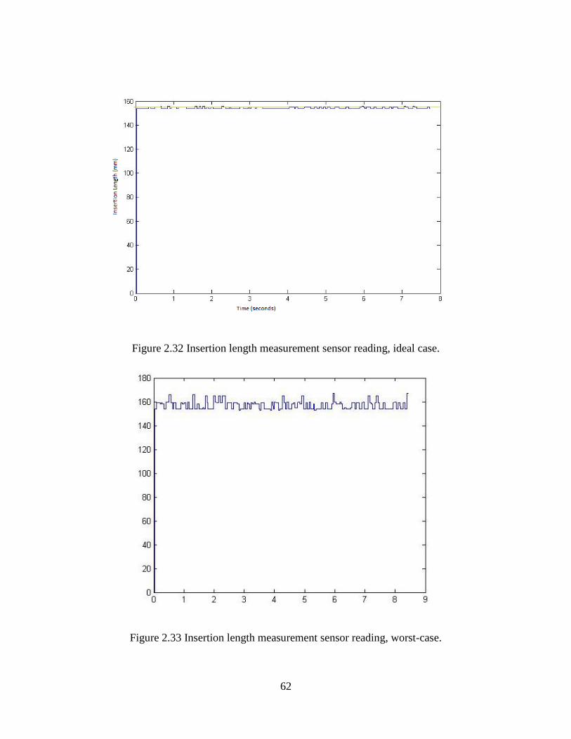
62
Figure 2.32 Insertion length measurement sensor reading, ideal case.
Figure 2.33 Insertion length measurement sensor reading, worst-case.
63
This system is meant to track the position as the tool is in motion. Thus, several
motion speeds and several constant insertion lengths are tested. Three different insertion
lengths and traversing speeds are shown in Figures 2.34, 2.35, and 2.36. Observing these
figures demonstrates how most length estimation errors are single-frame losses. In this
case, when the tool was furthest to the left (most negative encoder readings), the tip of the
tool was out of the field of view of the camera. By limiting the amount that the length
estimate is allowed to change between frames, a softer and more accurate signal can be
attained, minimizing these errors. The results of limiting the length estimation’s rate of
change are seen in Figure 2.37. The implemented length estimation filter simply rejects
inputs that are more than 20 millimeters away between individual measurements. With
about fifty measurements per second, making the assumption that the tool length
insertion speed is kept below 1 meter per second is quite valid. In Figure 2.37, the
complete motion is recorded, starting from insertion of the tool.
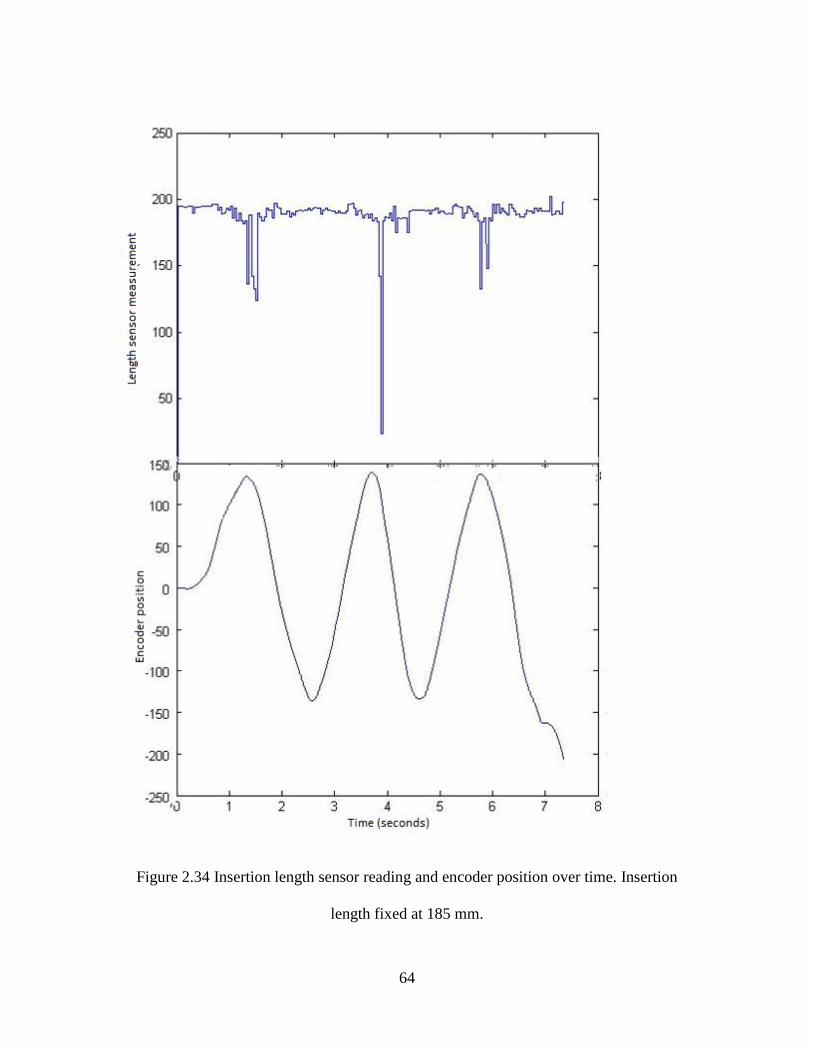
64
Figure 2.34 Insertion length sensor reading and encoder position over time. Insertion
length fixed at 185 mm.
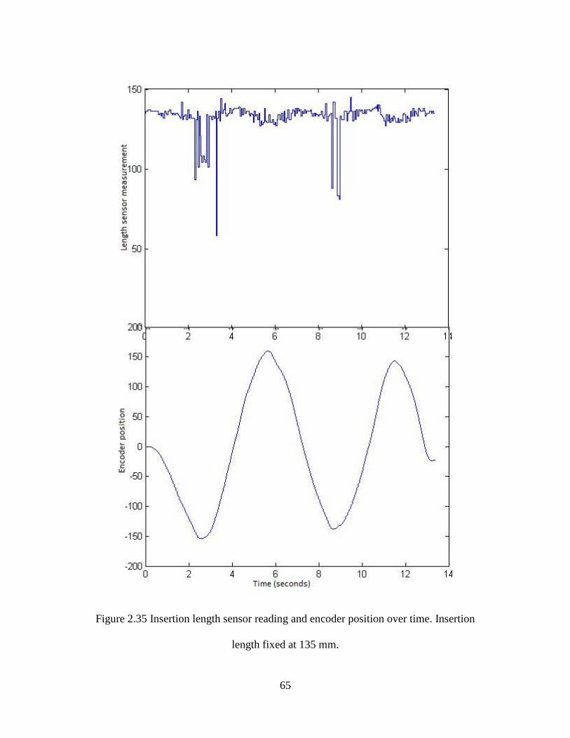
65
Figure 2.35 Insertion length sensor reading and encoder position over time. Insertion
length fixed at 135 mm.
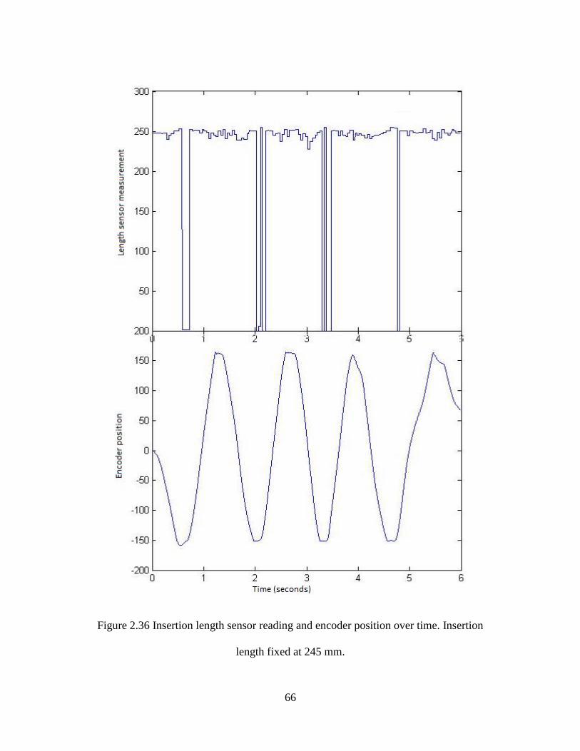
66
Figure 2.36 Insertion length sensor reading and encoder position over time. Insertion
length fixed at 245 mm.
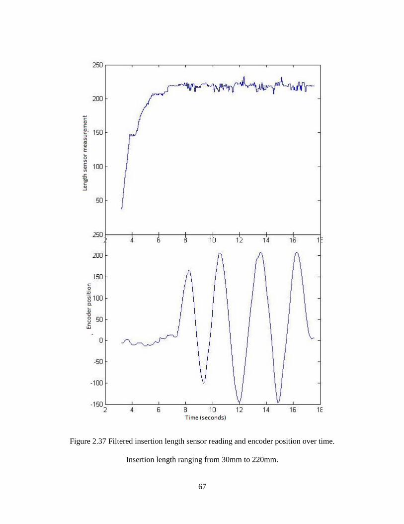
67
Figure 2.37 Filtered insertion length sensor reading and encoder position over time.
Insertion length ranging from 30mm to 220mm.
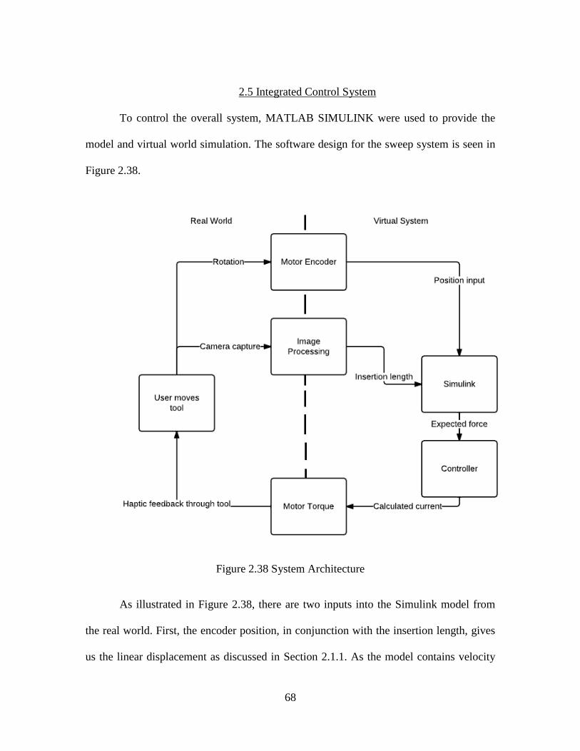
68
2.5 Integrated Control System
To control the overall system, MATLAB SIMULINK were used to provide the
model and virtual world simulation. The software design for the sweep system is seen in
Figure 2.38.
Figure 2.38 System Architecture
As illustrated in Figure 2.38, there are two inputs into the Simulink model from
the real world. First, the encoder position, in conjunction with the insertion length, gives
us the linear displacement as discussed in Section 2.1.1. As the model contains velocity
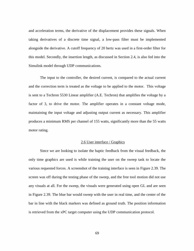
69
and acceleration terms, the derivative of the displacement provides these signals. When
taking derivatives of a discrete time signal, a low-pass filter must be implemented
alongside the derivative. A cutoff frequency of 20 hertz was used in a first-order filter for
this model. Secondly, the insertion length, as discussed in Section 2.4, is also fed into the
Simulink model through UDP communications.
The input to the controller, the desired current, is compared to the actual current
and the correction term is treated as the voltage to be applied to the motor. This voltage
is sent to a Techron 5530 Linear amplifier (A.E. Techron) that amplifies the voltage by a
factor of 3, to drive the motor. The amplifier operates in a constant voltage mode,
maintaining the input voltage and adjusting output current as necessary. This amplifier
produces a minimum RMS per channel of 155 watts, significantly more than the 55 watts
motor rating.
2.6 User interface / Graphics
Since we are looking to isolate the haptic feedback from the visual feedback, the
only time graphics are used is while training the user on the sweep task to locate the
various requested forces. A screenshot of the training interface is seen in Figure 2.39. The
screen was off during the testing phase of the sweep, and the free tool motion did not use
any visuals at all. For the sweep, the visuals were generated using open GL and are seen
in Figure 2.39. The blue bar would sweep with the user in real time, and the center of the
bar in line with the black markers was defined as ground truth. The position information
is retrieved from the xPC target computer using the UDP communication protocol.
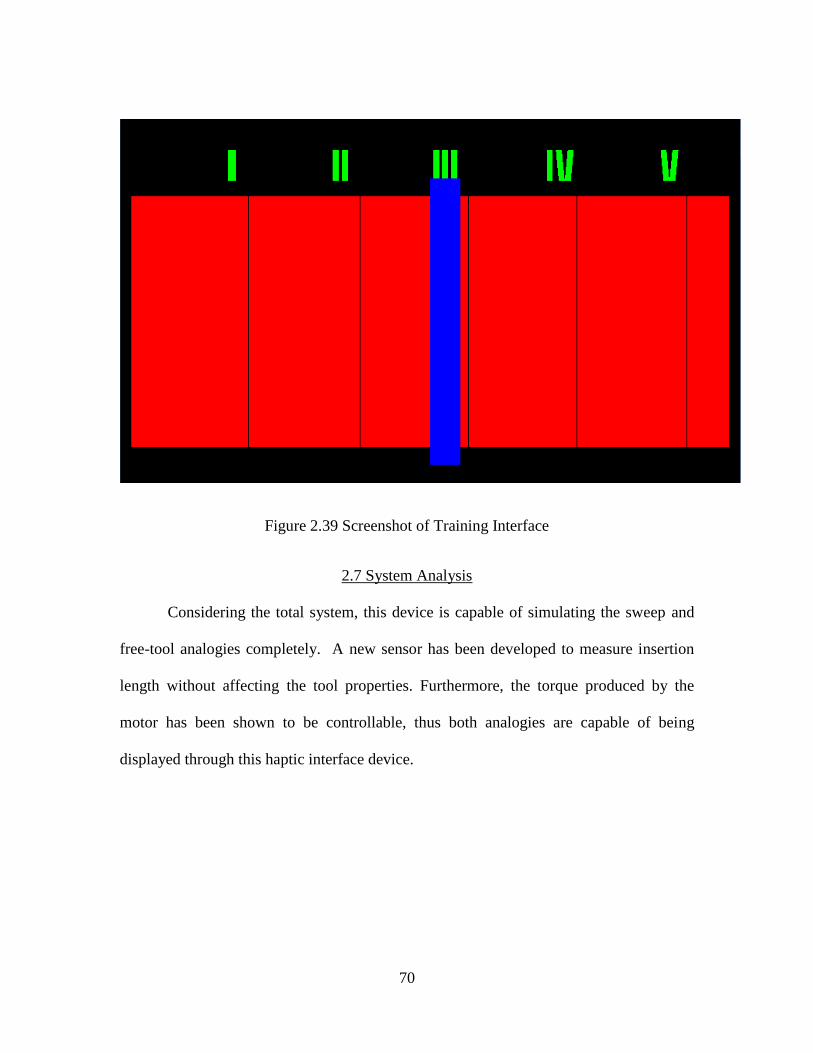
70
Figure 2.39 Screenshot of Training Interface
2.7 System Analysis
Considering the total system, this device is capable of simulating the sweep and
free-tool analogies completely. A new sensor has been developed to measure insertion
length without affecting the tool properties. Furthermore, the torque produced by the
motor has been shown to be controllable, thus both analogies are capable of being
displayed through this haptic interface device.
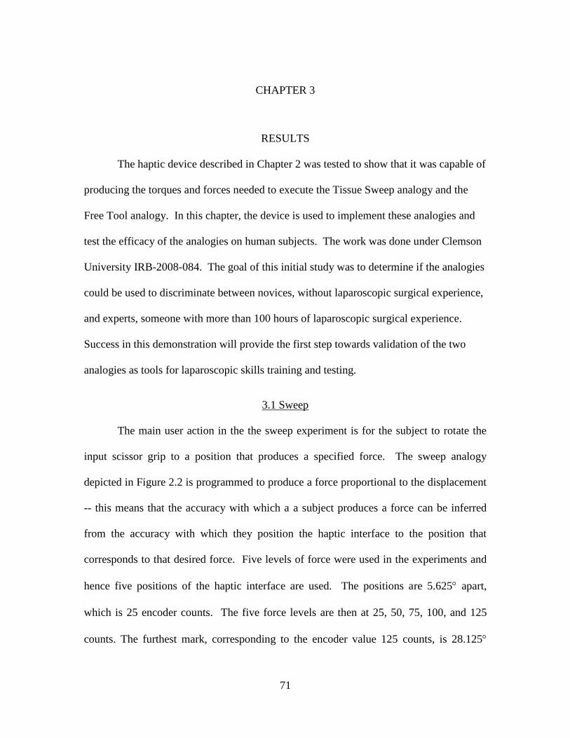
71
CHAPTER 3
RESULTS
The haptic device described in Chapter 2 was tested to show that it was capable of
producing the torques and forces needed to execute the Tissue Sweep analogy and the
Free Tool analogy. In this chapter, the device is used to implement these analogies and
test the efficacy of the analogies on human subjects. The work was done under Clemson
University IRB-2008-084. The goal of this initial study was to determine if the analogies
could be used to discriminate between novices, without laparoscopic surgical experience,
and experts, someone with more than 100 hours of laparoscopic surgical experience.
Success in this demonstration will provide the first step towards validation of the two
analogies as tools for laparoscopic skills training and testing.
3.1 Sweep
The main user action in the the sweep experiment is for the subject to rotate the
input scissor grip to a position that produces a specified force. The sweep analogy
depicted in Figure 2.2 is programmed to produce a force proportional to the displacement
-- this means that the accuracy with which a a subject produces a force can be inferred
from the accuracy with which they position the haptic interface to the position that
corresponds to that desired force. Five levels of force were used in the experiments and
hence five positions of the haptic interface are used. The positions are 5.625 apart,
which is 25 encoder counts. The five force levels are then at 25, 50, 75, 100, and 125
counts. The furthest mark, corresponding to the encoder value 125 counts, is 28.125
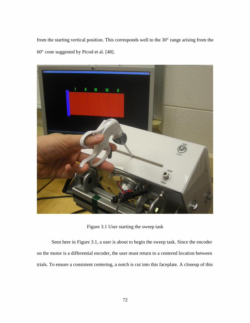
72
from the starting vertical position. This corresponds well to the 30 range arising from the
60 cone suggested by Picod et al. [48].
Figure 3.1 User starting the sweep task
Seen here in Figure 3.1, a user is about to begin the sweep task. Since the encoder
on the motor is a differential encoder, the user must return to a centered location between
trials. To ensure a consistent centering, a notch is cut into this faceplate. A closeup of this
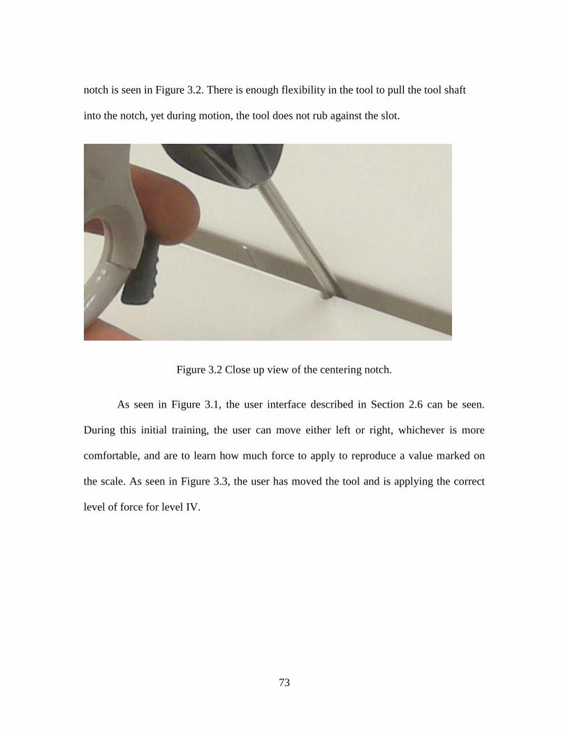
73
notch is seen in Figure 3.2. There is enough flexibility in the tool to pull the tool shaft
into the notch, yet during motion, the tool does not rub against the slot.
Figure 3.2 Close up view of the centering notch.
As seen in Figure 3.1, the user interface described in Section 2.6 can be seen.
During this initial training, the user can move either left or right, whichever is more
comfortable, and are to learn how much force to apply to reproduce a value marked on
the scale. As seen in Figure 3.3, the user has moved the tool and is applying the correct
level of force for level IV.
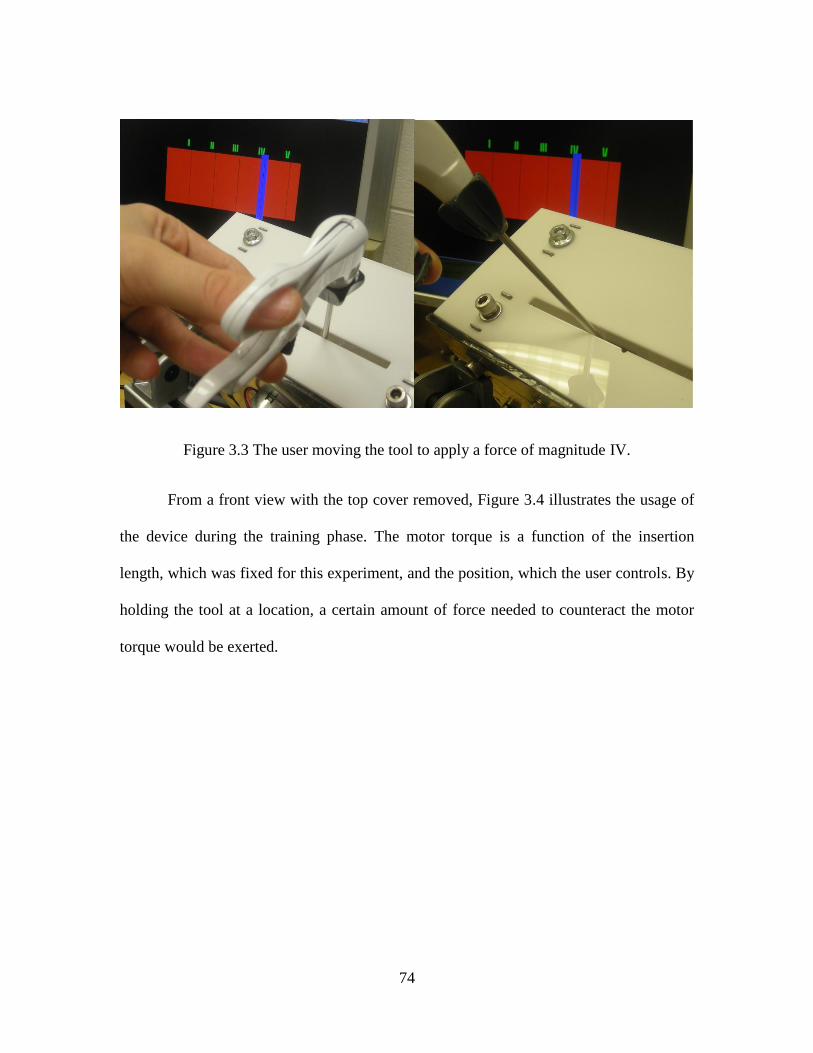
74
Figure 3.3 The user moving the tool to apply a force of magnitude IV.
From a front view with the top cover removed, Figure 3.4 illustrates the usage of
the device during the training phase. The motor torque is a function of the insertion
length, which was fixed for this experiment, and the position, which the user controls. By
holding the tool at a location, a certain amount of force needed to counteract the motor
torque would be exerted.
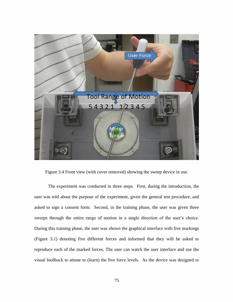
75
Figure 3.4 Front view (with cover removed) showing the sweep device in use.
The experiment was conducted in three steps. First, during the introduction, the
user was told about the purpose of the experiment, given the general test procedure, and
asked to sign a consent form. Second, in the training phase, the user was given three
sweeps through the entire range of motion in a single direction of the user’s choice.
During this training phase, the user was shown the graphical interface with five markings
(Figure 3.1) denoting five different forces and informed that they will be asked to
reproduce each of the marked forces. The user can watch the user interface and use the
visual feedback to attune to (learn) the five force levels. As the device was designed to

76
behave identically sweeping to the left and the right, the user has freedom to use
whichever hand that is most comfortable and sweep in whichever direction they like. In
the final testing phase, the subjects were asked to replicate each of the five possible force
levels three times, in random order as directed by the proctor. Each time the participant
stopped at what they thought to be the matching requested force. On a separate screen not
visible to the participant, the encoder value is displayed, and the proctor records the value
from the display. The training and test phases can be repeated for different spring
parameters, i.e. different force values at the five force testing positions.
3.1.1 Results
Two expert surgeons (n=2) were tested on a stiff spring with parameters m= 20g,
b = 11.4Nsm-1
, and k = 1000 Nm-1
. All responses from the surgeons are shown in Figure
3.5. A group of four novices were recruited from a pool of introductory psychology
course students and tested on the stiff spring sweep analogy. The novices received extra
credit in their psychology course, but no other compensation. The novice responses are
shown in Figure 3.6.
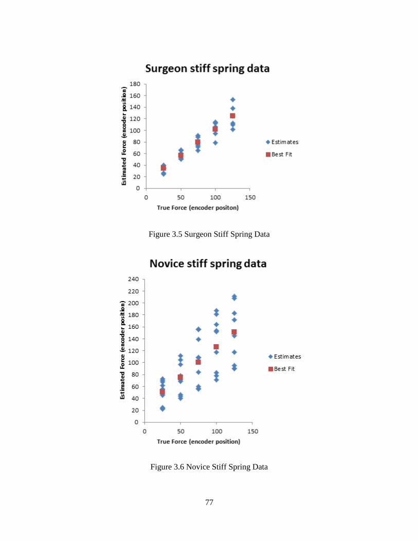
77
Figure 3.5 Surgeon Stiff Spring Data
Figure 3.6 Novice Stiff Spring Data

78
The surgeons were also tested on a soft spring, the simulation model had the
following parameters: m = 20g, b = 8.4Nsm-1
, and k = 500 Nm-1
. The reason for
changing b is due to early testing suggesting that maintaining the natural frequency of the
system
√ would provide a similar spring response time. The results from
the two surgeons are shown in Figure 3.7. The four novices that completed the stiff
spring test also completed the soft spring test and an additional novice subject who did
not complete the stiff spring task was added. The novice data is shown in Figure 3.8.
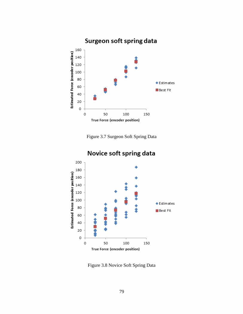
79
Figure 3.7 Surgeon Soft Spring Data
Figure 3.8 Novice Soft Spring Data
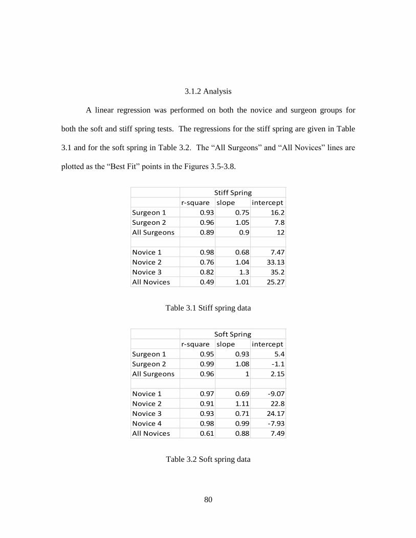
80
3.1.2 Analysis
A linear regression was performed on both the novice and surgeon groups for
both the soft and stiff spring tests. The regressions for the stiff spring are given in Table
3.1 and for the soft spring in Table 3.2. The “All Surgeons” and “All Novices” lines are
plotted as the “Best Fit” points in the Figures 3.5-3.8.
r-square slope intercept
Surgeon 1 0.93 0.75 16.2
Surgeon 2 0.96 1.05 7.8
All Surgeons 0.89 0.9 12
Novice 1 0.98 0.68 7.47
Novice 2 0.76 1.04 33.13
Novice 3 0.82 1.3 35.2
All Novices 0.49 1.01 25.27
Stiff Spring
Table 3.1 Stiff spring data
r-square slope intercept
Surgeon 1 0.95 0.93 5.4
Surgeon 2 0.99 1.08 -1.1
All Surgeons 0.96 1 2.15
Novice 1 0.97 0.69 -9.07
Novice 2 0.91 1.11 22.8
Novice 3 0.93 0.71 24.17
Novice 4 0.98 0.99 -7.93
All Novices 0.61 0.88 7.49
Soft Spring
Table 3.2 Soft spring data
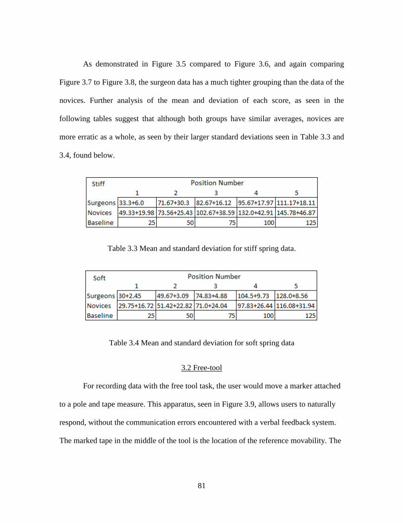
81
As demonstrated in Figure 3.5 compared to Figure 3.6, and again comparing
Figure 3.7 to Figure 3.8, the surgeon data has a much tighter grouping than the data of the
novices. Further analysis of the mean and deviation of each score, as seen in the
following tables suggest that although both groups have similar averages, novices are
more erratic as a whole, as seen by their larger standard deviations seen in Table 3.3 and
3.4, found below.
Table 3.3 Mean and standard deviation for stiff spring data.
Table 3.4 Mean and standard deviation for soft spring data
3.2 Free-tool
For recording data with the free tool task, the user would move a marker attached
to a pole and tape measure. This apparatus, seen in Figure 3.9, allows users to naturally
respond, without the communication errors encountered with a verbal feedback system.
The marked tape in the middle of the tool is the location of the reference movability. The
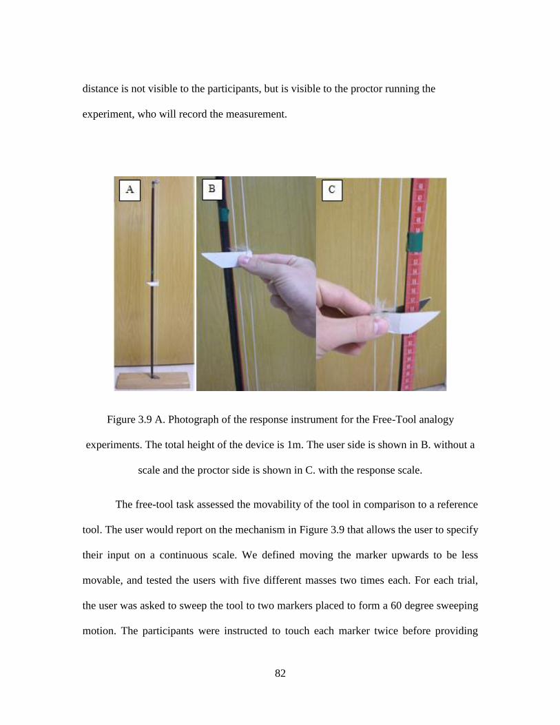
82
distance is not visible to the participants, but is visible to the proctor running the
experiment, who will record the measurement.
Figure 3.9 A. Photograph of the response instrument for the Free-Tool analogy
experiments. The total height of the device is 1m. The user side is shown in B. without a
scale and the proctor side is shown in C. with the response scale.
The free-tool task assessed the movability of the tool in comparison to a reference
tool. The user would report on the mechanism in Figure 3.9 that allows the user to specify
their input on a continuous scale. We defined moving the marker upwards to be less
movable, and tested the users with five different masses two times each. For each trial,
the user was asked to sweep the tool to two markers placed to form a 60 degree sweeping
motion. The participants were instructed to touch each marker twice before providing

83
their response. Between every testing run, the user was given the reference mass. There
were two masses lighter than the reference, two masses heavier than the reference, and
the reference was also repeated. Again, when referring to these as changing masses, the
exact same effect would be attained by changing the length of the simulated tool in this
case, as the tool remained fixed at a constant length in this test.
3.2.1 Data
The raw data and the regression line is shown in Figures 3.10 and 3.11. Three
surgeons were tested, and although one surgeon had an interruption, only the remaining
two points after the interruption were discarded. The R2 value for the surgeon set is 0.68,
with a best fit slope of -12.31 and intercept of 101.32. Four novices were tested, and the
R2 value for the novice set is 0.72, with a best fit slope and intercept of -9.38 and 89.79
respectively
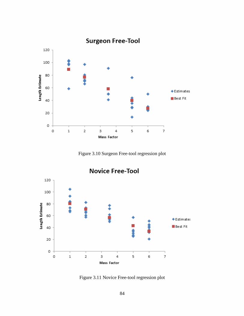
84
Figure 3.10 Surgeon Free-tool regression plot
Figure 3.11 Novice Free-tool regression plot

85
3.2.2 Analysis
For the free-tool experiment, surgeons did not outperform novices, yet novices
did not outperform surgeons considerably either. Perhaps free tool motion in the form of
length perception is not a differentiating skill between surgeons and novices. However,
before length perception can be completely discarded, f. Perhaps surgeons and novices
perform differently when restricted to a smaller range of motion. Another idea mentioned
by one of the participants consisted of giving a more full range of references, thus the
length perception of very short or very long devices could be compared across users.

86
CHAPTER 4
CONCLUSIONS
As demonstrated here, an inexpensive device to discern haptic ability is feasible.
However, careful concern must be given to the design of the experiment to avoid
confusion and to ensure participant understanding. Measured force application is not a
regular movement to most individuals; instead most movements are done without
conscious thought to the level of force application, and most often are done with the
correct amount of force. Laparoscopy however introduces situations where conscious
thought towards force application arises. Thus, force application training should be
considered.
4.1 Analysis of results
With the sweep test, most users reported a very good feeling about their
performance on this task. Many participants in both the surgeon and novice groups
reported that the spring felt very realistic and was very responsive to their input.
Although this model did not differentiate users perfectly, as one novice performed
exceptionally well (novice 4 as seen in Table 3.2), the two populations were very
distinguishable as a whole. This task could be used for force training in future
applications.
With the free-tool analogy, a common complaint was the confusion of
participants. Very often, participants would ask for clarification on which direction to
move the reporting device for a more or less movable tool. When instructed to move the

87
tool upwards indicating a less movable tool, participants occasionally showed signs of
confusion, as they were reporting a shorter appearing, and thus more movable, stick at the
higher end of the measuring device. Often, a participant would remark that the tool seems
lighter, and then move the measuring device upwards, indicating a less movable tool.
This confusion shows in the raw data, as some participants first starting have great
correlation, then for no apparent reason mark a very movable stick as being the complete
opposite. Usually these users would ask for clarification, but not always immediately.
4.2 Future work
Some planned future work for this includes incorporating the other tool motions.
Currently, several separate devices are used, usually one analogy per device. By
integrating the devices together into a single system, the user could efficiently train on all
the haptic analogies.
Some other future concepts to refine this device would be to include a more
complete data profile on the users. Notably, not only record what value the users score,
but how fast the user reaches this value and how far they overshoot the value as well.
This could show other areas in which the expert user would outperform the novice. A
combination of time, accuracy, and overshoot could then combine to give a stronger
representation of the force profile of a novice and an expert than simply the accuracy.
In coordination with other members of the research group, who have implemented
pushing and grasping models, a full device that covers all the analogies can be realized,
creating a combined training device for all different laparoscopic interactions.

88
REFERENCES
[1] J. J. Gibson, The Senses Considered as Perceptual Systems. Westport, Connecticut,
United States of America: Greenwood Press., 1983.
[2] E.G. Boring, "Sensation and Perception in the History of Experimental Psychology,"
D. Appleton-Century Company, New York, London, 1942.
[3] E Titchener, Lectures on Elementary Psycholoy of Feeling and Attention. New
York: The Macmillan Company, 1908.
[4] J.M. Loomis and S.J. Lederman, "Tactual Perception," in Handbook of Human
Perception and Performance, K.B. Boff, L. Kaufmann, and J. Thomas, Eds.: Wiley,
1986, ch. 31, pp. 31-1 - 31-41.
[5] R. L. Klatzky and S. J. Lederman, "Touch," in Handbook of Psychology, Volume 4:
Experimental Psycholody, A.F. Healy and R.W. Proctor, Eds.: John Wiley and Sons,
2003, ch. 6, pp. 147-176.
[6] R.S. Johansson and A.B. Vallbo, "Tactile Sensory Coding in the Glabrous Skin of
the Human Hand," Trends in Neuroscience, vol. 6, pp. 27-32, 1983.
[7] Centers for Disease Control and Prevention, "Guideline for prevention of surgical
site infection," Infection Control and Hospital Epidemiology, 20(4):247-278, 1999.
[8] F. J. Clark and K. W. Horch, "Kinesthesia," in Handbook of Perception & Human
Performance, K.R. Boff, L Kaufman, and J.P. Thomas, Eds. New York: John Wiley
& Sons, 1986, ch. 13, pp. 13-1-13-62.
[9] L. A. Jones, "Somatic Senses 3: Proprioception," in Neuroscience for Rehabilitation,
Helen Sue Cohen, Ed. New York: Lippincott, Williams & Wilkins, 1999, ch. 8, pp.
111-130.
[10] S.J. Lederman and R.L. Klatzky, "Hand Movements: A Window Into Haptic Object
Recognition," Cognitive Psychology, vol. 19, no. 3, pp. 342-368, July 1987.
[11] S. J. Biggs and M. A. Srinivasan, "Haptic Interfaces," in Handbook of Virtual
Environments: Design, Implementation, and Applications, K. Stanney, Ed. London,
England: Lawrence Earlbaum, Inc., ch. 5, pp. 93-116.
[12] R. Q. Van der Linde, P. Lammerste, E. Frederiksen, and B. Ruiter, "The
HapticMaster, a new high-performance haptic interface," FCS Control Systems, The

89
Netherlands, 2002.
[13] M Grünwald, Human Haptic Perception: Basics and Applications. Basel, Germany:
Birkhäuser Verlag, 2008.
[14] O. Meckel, "Control of Haptic Systems," in Engineering Haptic Devices, Thorston
Kern, Ed. Germany: Springer, 2009, ch. 7, pp. 131-163.
[15] T. Kern and O. Meckel, "Internal Structure of Haptic Systems," in Engineering
Haptic Devices: A Beginner's Guide for Engineers, Thorsten Kern, Ed. Berlin,
Germany: Springer Berlin Heidelberg, 2009, ch. 5.
[16] J. B. F. van Erp, "Tactile Navigation Display," Lecture Notes in Computer Science,
vol. 2058/2001, pp. 165-173, 2001.
[17] G. Yang et al., "A Haptic Device Wearable on a Human Arm," in Proceedings of the
2004 IEEE Conference on Robotics, Automation, and Mechatronics, Singapore,
2004.
[18] D. Tsetserukou, A. Neviarouskaya, H. Predinger, N. Kawakami, and S. Tachi,
"Affective Haptics in Emotional Communication," in International Conference on
Affective Computing and Intelligent Interaction, Amsterdam, 2009.
[19] CyberGlove Systems CyberGrasp From Inition. [Online].
http://www.inition.co.uk/inition/dispatcher.php?action=get&model=products&URL
_=product_glove_vti_grasp&SubCatID_=26&tab=blurb
[20] S.D. Laycock and A.M. Day, "Recent Developments and Applications of Haptic
Devices," Gomputer Graphics Forum, vol. 22, no. 2, pp. 117-132, 2003.
[21] Sensable. (2011) Phantom Omni - Sensable. [Online].
http://www.sensable.com/haptic-phantom-omni.htm
[22] Novint Technologies, Inc. (2011) Novint Falcon. [Online].
http://www.novint.com/index.php?option=com_content&view=article&id=39&Item
id=123
[23] Force Dimension. (2011) Force Dimension - Products. [Online].
http://www.forcedimension.com/products
[24] Sensable. (2011) FreeForm Systems - Sensable. [Online].
http://www.sensable.com/products-freeform-systems.htm

90
[25] Tactus Technologies, Inc. (2011) Protean. [Online]. http://www.proteanclay.com/
[26] C. Basdogan, S. De, J. Kim, M. Muniyandi, and H. Kim, "Haptics in Minimally
Invasive Surgical Simulation and Training," Computer Graphics and Applications,
IEEE, vol. 24, no. 2, pp. 56-64, March/April 2004.
[27] W. Provancher. (2010, August) Utah Telerobotics. [Online].
http://www.telerobotics.utah.edu/index.php/Research/AdmittanceDevices
[28] V. Haywayd, O. R, Cruz-Hernandes, M. Astley, D. Grant, and G. Robles-De-La-
Torre, "Haptic Interfaces and Devices," Sensor Review, vol. 24, no. 1, pp. 16-29,
2004.
[29] K. Kim, J. E. Colgate, J. J. Santos-Munné, A. Makhlin, and M. A. Peshkin, "On the
Design of Miniature Haptic Devices for Upper Extremity Prosthetics," IEEE/ASME
Transactions on Mechatronics, vol. 15, no. 1, February 2010.
[30] M. Hatzinger et al., "Hans Christian Jacobaeus: Inventor of Human Laparoscopy
and Thoracoscopy," Journal of Endourology, vol. 20, no. 11, November 2006.
[31] CDC/NCHS, National Hospital Discharge Survey, 2009.
[32] Society of American Gastrointestinal and Endoscopic Surgeons. (2003-2010)
Fundamentals of Laparoscopic Surgery. [Online].
http://www.flsprogram.org/index/fls-objectives/
[33] L. L. Swanstrom, G. M. Fried, K. I Hoffman, and N. J. Soper, "Beta Test Results of
a New System Assessing Competence in Laparoscopic Surgery," Journal of the
American College of Surgeons, vol. 202, no. 1, pp. 62-69, January 2006.
[34] G.M. Fried et al., "Proving the Value of Simulation in Laparoscopic Surgery,"
Annals of Surgery, vol. 240, no. 3, pp. 518-528, September 2004.
[35] J. Signapogu, "Validating a Set of Haptic Simulators for Evaluating Salient Force-
based Skills for Laparoscopic Surgery," Clemson University, PhD Proposal 2011.
[36] Intuitive Surgical, Inc. (2008) da Vinci Surgery - Minimally Invasive Robotic
Surgery with the da Vinci Surgical System. [Online].
http://www.davincisurgery.com/
[37] Intuitive Surgical, Inc. (2010) Intuitive Surgical - Company FAQ. [Online].
http://www.intuitivesurgical.com/company/faqs.html#19

91
[38] Intuitive Surgical, Inc. (2011, April) Intuitive Surgical Investor Presentation Q1
2011. [Online]. http://phx.corporate-
ir.net/External.File?item=UGFyZW50SUQ9OTE1MTR8Q2hpbGRJRD0tMXxUeX
BlPTM=&t=1
[39] M.S. Wilson, A. Middlebrook, C. Sutton, R Stone, and R.F. McCloy, "MIST VR: a
virtual reality trainer for laparoscopic surgery assesses performance," Annals of the
Royal College of Surgeons of England, vol. 79, pp. 403-404, 1997.
[40] T.P. Grantcharov et al., "Randomized Clinical Trial of Virtual Reality Simulation
for Laparoscopic Skills Training," British Journal of Surgery, vol. 91, pp. 146-150,
2004.
[41] A.J. Duffy et al., "Construct Validity for the LAPSIM Laparoscopic Surgical
Simulator," Surgical Endoscopy, vol. 19, pp. 401-405, 2005.
[42] E.M. McDougall et al., "Construct Validity Testing of a Laparoscopic Surgical
Simulator," Journal of the American College of Surgeons, vol. 202, no. 5, pp. 779-
787, May 2006.
[43] M. W. Salkini et al., "The Role of Haptic Feedback in Laparoscopic Training Using
the LapMentor II," Journal of Endourology, vol. 24, no. 1, pp. 99-102, January
2010.
[44] D Morris, H Tan, F Barbagli, T Chang, and K Salisbury, "Haptic Feedback
Enhances Force Skill Learning," in IEEE Eurohaptics Conference and Symposium
on Haptic Interfaces for Virtual Environment and Teleoperator Systems, Tsukaba,
2007.
[45] P.L. Youngblood et al., "Comparison of Training on Two Laparoscopic Simulators
and Assessment of Skills Transfer to Surgical Performance," Journal of the
American College of Surgeons, vol. 200, no. 4, pp. 546-551, April 2005.
[46] C. Richards, J Rosen, B Hannaford, C Pellegrini, and M Sinanan, "Skills Evaluation
in Minimally Invasive Surgery Using Force/Torque Signatures," Surgical
Endoscopy, vol. 14, pp. 791-798, 2000.
[47] S. Choi and H. Z. Tan, "Effect of Update Rate on Perceived Instability of Virtual
Haptic Texture," in Proceedings of 2004 IEEE/RSJ International Conference on
Intelligent Robots and Systems, Sendai, Japan, 2004, pp. 3577-3582.
[48] G. Picod, A.C. Jambon, D. Vinatier, and P. Dubois, "What can the operator actually
feel when performing a laparoscopy?," Surgical Endoscopy, vol. 19, pp. 95-100,

92
2005.
[49] Willow Garage. (2011) OpenCV Wiki. [Online]. opencv.willowgarage.com/wiki/
[50] CL Teo, E. Burdet, and HP Lim, "A Robotic Teacher of Chinese Handwriting," in
10th Symposium on Haptic Interfaces for Virtual Environments and Teleoperator
Systems, 2002.
[51] D. Feygin, M. Keehner, and F. Tendick, "Haptic Guidance: Experimental Evaluation
of a Haptic Training Method for a Perceptual Motor Skill," in Proceedings of the
10th Symposium on Haptic Interfaces for Virtual Environments and Teleoperator
Systems, 2002.
[52] R. B. Gillespie, M. S. O'Modhrain, P. Tang, D. Zaretzky, and C. Pham, "The Virtual
Teacher," in Proceedings of the ASME Dynamic Systems and Control Division,
Anaheim, CA, 1997, pp. 171-178.
[53] S. M. Hetzler and R. M. Tardiff, "The Three "R"s: Real Students in Real Time
Doing Real Work Learning Calculus," in Proceedings of the 13th International
Conference on Auditory Display, Montréal, Canada, 2007.
[54] J. Mullins, C. Mawson, and S. Nahavandi, "Haptic Handwriting Aid for Training
and Rehabilitation," in IEEE International Conference on Systems, Man and
Cybernetics, 2005, pp. 2690-2694.
[55] A. M. Okamura, C. Richard, and M. R. Cutkosky, "Feeling is Believing: Using a
Force-Feedback Joystick to Teach Dynamic Systems," Journal of Engineering
Education, vol. 92, no. 3, pp. 345-349, July 2002.
[56] C. Richard, A. M. Okamura, and M. R. Cutkosky, "Getting a Feel for Dynamics:
Using Haptic Interface Kits for Teaching Dynamics and Controls," in ASME IMECE
6th Annual Symposium on Haptic Interfaces, Dallas, TX, 1997.
[57] G. Sankaranarayanan, S. Weghorse, M. Sanner, A. Gillet, and A. Olson, "Role of
Haptics in Teaching Structural Molecular Biology," in 11th Symposium on Haptic
Interfaces for Virtual Environment and Teleoperator Systems, Los Angeles, 2003, p.
363.
[58] B. Siciliano and O. Khatib, Springer Handbook of Robotics, illustrated ed.: Springer,
2008.
[59] C. Sjöström, H. Danielsson, C. Magnusson, and K. Rassmus-Gröhn, "Phantom-
based Haptic Line Graphics for Blind Persons," Visual Impairment Research, vol. 5,

93
no. 1, pp. 13-32, 2003.
[60] K. G. Snook, "A Continuum of Choice: Instructional Techniques in Undergraduate
Mathematics," in Changing Core Mathematics, Chris Arnet and Donald Small, Eds.
United States of America: Mathematical Association of America, 2002, pp. 143-149.
[61] J. Solis, C. A. Avizzano, and M. Bergamasco, "Teaching to Write Japanese
Characters using a Haptic Interface," in Symposium on Haptic Interfaces for Virtual
Environment and Teleoperator Systems, 2002, pp. 255-262.
[62] F. Van Scoy, D. McLaughlin, and A. Fullmer, "Auditory Augmentation of Haptic
Graphs: Developing a Graphic Tool for Teaching Precalculus Skill to Blind
Students," in ICAD 05-Eleventh Meeting of the International Conference on
Auditory Display, Limerick, Ireland, 2005.
[63] F. L. Van Scoy, T. Kawai, M. Darrah, and C. Rash, "Haptic Display of
Mathematical Functions for Teaching Mathematics to Students with Disabilities:
Design and Proof of Concept," Lecture Notes in Computer Science, vol. 2058/2001,
pp. 31-40, 2001.
[64] R. L. Williams, M.-Y. Chen, and J. M. Seaton, "Haptics-Augmented Simple-
Machine Educational Tools," Journal of Science Education and Technology, vol. 12,
no. 1, March 2003.
[65] R. L. Williams II, M.-Y. Chen, and J. M. Seaton, "Haptics-Augmented Simple-
Machine Educational Tools," Journal of Science Education and Technology, vol. 12,
no. 1, March 2003.


![Evaluating Angular Accuracy of Wrist based Haptic ... · 1 INTRODUCTION Haptic guidance for the hand can be useful for a range of applications, including virtual reality [26, 33],](https://img.pdfslide.us/doc/110x75/5fc203fa5bc8ac21d916f305/evaluating-angular-accuracy-of-wrist-based-haptic-1-introduction-haptic-guidance.jpg)


![Modeling and Synthesis of Tactile Texture with Spatial ...€¦ · texture perception on a surface haptic device. Friction mod-ulation surface haptic devices, such as TPad [19], [20],](https://img.pdfslide.us/doc/110x75/5f884e64f0f0ef583f5894b3/modeling-and-synthesis-of-tactile-texture-with-spatial-texture-perception-on.jpg)