Embed Size (px)
Citation preview

Design Optimization of the Tau Haptic Device
Suleman Khan Machine Design Dept. Royal Institute of Technology-KTH
Stockholm, Sweden. [email protected]
Aftab Ahmad Machine Design Dept. Royal Institute of Technology-KTH
Stockholm, Sweden. [email protected]
Kjell Andersson Machine Design Dept. Royal Institute of Technology-KTH
Stockholm, Sweden. [email protected]
Abstract— The work presented in this paper is motivated by the use of haptics in medical simulation, particularly simulation of surgical procedures in hard tissue such as bone structures. In this context, characteristics such as motion, stiffness, workspace-to-footprint ratio, and low inertia are key factors in the design of a haptic device. This paper introduces a procedure for design optimization of haptic devices based on a hybrid mechanism. For design optimization, performance indices such as workspace volume, kinematic isotropy and static torque requirements indices are defined. A new multi-criteria objective optimization (MOO) function is introduced to define the optimization problem. Multi-objective algorithms are used to solve this optimization problem using the defined objective function. Furthermore sensitivity analysis of the performance indices against each design parameter is presented as a basis for selecting a final set of design parameters to develop a prototype. Finally, a CAD model and prototype of the device is developed based on the simulation results.
Keywords-component; Haptic devices, design optimization, TAU mechanism, genetic algorithm, modeling and simulation.
I. INTRODUCTION
A haptic device is a mechanical structure that creates a link between the human sense of touch and virtual reality. It reflects forces and torques based on what the operator discovers by interaction with in the virtual or remote world. Haptic applications are expanding rapidly in various fields such as medicine, telerobotics, engineering design, and entertainment [1]. The intended application of the device presented in this paper is in haptic milling simulator [1]. In this scenario a haptic device is used to achieve manipulation capabilities and force/torque feedback in six degrees of freedom (6-DoF) during simulation of surgical procedures in hard tissue such as bone structures. Such procedures involve removing bone by drilling or milling, including processing of channels and cavities, hence requiring 5 to 6 degrees of freedom, as well as feedback from stiff contacts. A similar field of application is dentistry and dental surgery.
The application context, surgery in bone structures, leads to two main haptic device requirements that are not simultaneously met by any commercially available device that we have found. These requirements are [2]:
Haptic feedback in six degrees of freedom to allow both force and torque feedback from a virtual tool
operating in a (narrow) channel or cavity.
Device stiffness and force/torque performance that allow realistic simulation of stiff tool-to-bone contacts.
Mechanical structures currently used in similar devices include serial as well as parallel configurations. However, both structures have some advantages and drawbacks. Parallel structure provide high payload, stiffness, accuracy, and low inertia with the actuators located on the fixed base [3]. But the workspace of the parallel structure is small as compared to the serial structure. On the other hand serial structure has low forces and stiffness capabilities and high inertia. Thus in this work a hybrid structure called Tau structure is introduced that combine the best characteristics of both parallel and serial structures. But the performance of hybrid/parallel kinematic structures is highly dependent on their geometry and dimensions [4]. Thus it is vital to consider dimension synthesis and structural design parameter optimization in order to achieve desired/optimal performance. The design optimization of hybrid/parallel mechanisms is challenging due to the complexity of their kinematics, dynamics, and singularities [3]. Further investigation and development is required to obtain optimal performance.
A. Literature review
Recently, many haptic devices have been developed and some of these have been commercialized [5]. Such as the Phantom by Massie [6, 7], HAPTION Virtouse 6D35-45 [8], and Freedom 6S [9] are haptic devices based on serial mechanisms with suitable workspace for the intended application but with insufficient stiffness and force/torque capacity. Also many researchers have proposed parallel mechanism based haptic devices due to their high stiffness and accuracy. Six-DoF Delta and Omega haptic devices from Force Dimension [10,11], a modified Delta device and Haptic master developed by Tsumaki et al. [12], a 6-URS parallel haptic device developed by J.M. Sabatera et al. [13], and a new 6-DoF haptic device developed at CEA-LIST [14], all for desktop applications, are some examples of parallel mechanisms. However, all these devices have the drawback of having either a small workspace or high inertia.
Research is therefore focusing on hybrid mechanisms that combine the advantages of parallel and serial mechanisms to obtain sufficient stiffness, enough workspace, and a compact design. Hongliang Cui et al. [15] have worked on the kinematic analysis and error modeling of a new 3-DoF mechanism, based 978-963-8111-77-7

on a serial–parallel mechanism, called the 3-DoF TAU parallel robot. Similarly Zhenqi Zhu et al. [16] have developed kinematic and dynamic model for real-time control of Tau parallel robot. However, no effort has been made to develop the kinematics of 6-DoF TAU devices. We have modeled and analyzed different concepts of 6-DoF TAU haptic devices, to identify their best characteristics [2, 17]. In this paper our focus is on design optimization of this new proposed 6-DoF TAU haptic device.
Finding an optimal solution for a hybrid/parallel kinematic structure involves a multi-criteria design optimization problem that is in general constrained, non-linear, and non-convex with no explicit analytical expression. The gradient and Hessian algorithms that generally converge to a local minimum are thus not suitable for solving this problem. An interval analysis based approach was recently applied by Hao [18] to solve a multi-criteria design problem for parallel manipulators. This method determines design parameter spaces that satisfy all design constraints but requires explicit analytical expressions of all constraints. Performance-chart based design methodology (PCbDM) proposed by X.-J. Liu [19] is an optimal kinematic design methodology for parallel mechanisms with a maximum of four linear design parameters, and is thus not suitable for our optimization problem with six design parameters(see section II-B).
On the other hand, multi-objective genetic algorithms (MOGA) [20] and non-domination based genetic algorithms (NSGA-II) [21] seem to be good candidates for these multi-criteria problems due to their ability to explore a Pareto front (solution) and due to their robustness. Stan [22], JH. Lee [23], Hwang [24], Guigue [25] and Gao [26] all used a genetic algorithm approach for multi-criteria optimization of parallel/hybrid kinematics structure.
The remaining of the paper is organized in sections. Section II presents design methodology and kinematics structure, section III deals with the performance indices and optimization. Furthermore results and discussion are presented in section IV and V.
II. DESIGN METHODOLOGY AND KINEMATIC STRUCTURE
A design methodology for a systematic design and optimization of haptic devices was developed and presented by the authors in [2]. In the first step, a list of specifications was obtained in dialogue with a prospective user. Then three different conceptual models were developed and analyzed in the multibody systems (MBS) software Adams View® [27]. On the basis of these analyses, a modified TAU hybrid kinematic structure [17] for the described problem was selected for further development, due to its relatively large workspace, low inertia and its ability to provide enough stiffness. In the next step a kinematic model of the selected mechanism was developed [17] as a basis for optimization. The design optimization and performance evaluation phase of the design methodology are the main focus of this paper.
A. Specification and requirements
The requirements given here were obtained in discussion with a prospective user, in this case a surgeon. It should be
noted that it is difficult to obtain specific requirements since the application domain is completely new and unique. The specifications should thus be treated as preliminary and as a rough estimate for the first prototype design. However, from a qualitative perspective the specifications give a good enough starting point. The list of preliminary specifications for the design of the device is given below [2]:
The device should have 6 actuated degrees of freedom [6-DoF input/output] motion.
The whole device [footprint] should fit within the space of 250 x 250 x 300 mm.
The translational workspace should be a minimum of 50 x 50 x 50 mm with no singularities within that space.
The rotational workspace should be ±40 degrees in all directions (at the center of the translation workspace).
The tool center point (TCP) force and torque performance should be at least 50 N and 1 Nm respectively.
It should be possible to place the device on a table in front of the user, with ease to access.
B. Kinematic structure
The selected TAU configuration is a hybrid parallel, serial mechanism consists of a fixed I-column, a moving platform and three parallel chains (1, 2 and 3) which connect the base frame to the moving platform as shown in Fig 1. In this structure chain 1 and chain 2 are symmetrical while chain 3 is unsymmetrical. Each symmetrical chain has two active rotational actuators, one attached to the I-column while another one is mounted on the active links U1 and U2. Furthermore chain 1 and 2 have extra two proximal links connecting the platform to active links U1 and U2 to increase the structural stiffness. The third chain, chain 3, has also two active rotational actuators, one attached to the I-column and the other one is mounted at the top of the device. This concept is an asymmetric serial-parallel configuration that provides 6-DoF motion at moving platform (see fig 1 and 2).
Figure 1. Conceptual model of the TAU 6-DoF haptic device[17].
A parametric model of the selected structure has been developed for the optimization process. For simplicity five

design parameters were considered: parameter d is used to position each parallel chain with respect to the base coordinate system {N} is at 1.5d, 3d and 4.5d respectively according to the preliminary analysis done for the maximum workspace and minimum actuator torques in ADAMS [27], length L1 of the active arm, length L2 of proximal links in each chain, radius of platform Rp, elevation angle θ32nom (nominal angle for θ32) of the active arm U3 of chain 3 with orientation of the base frame as given in Fig. 2.
Figure 2. Kinematic model and design parameters for optimization.
The kinematic model of the selected structure has been developed and analyzed in the second step of design methodology [17]. Hence in this paper we will focus only on the design optimization and performance evaluation of the device, based on the kinematics (Jacobian matrix) derived in previous work [17]. The Jacobian is a 6 x 6 matrix which has terms for both translational and rotational velocities to represent the 6-DoF motion. Thus the elements of the Jacobian matrix have different units, and normalization is required for unit’s consistency.
Different normalization techniques were found in the literature [28]. Tandridge et al. [29] normalize the Jacobian matrix using a characteristic length (CL). The entries of the Jacobian matrix with units of length were divided by CL to get a uniform Jacobian matrix. For the same purpose, Ma et al. [30] used the average distance from the centroid of the moving platform to the joints of the platform as a natural length. The nominal length (NL) defined as the distance from the origin of the base frame to the center of the platform, was used by JH. Lee [23]. It is clear that the choice of scale factor greatly affects the performance measure and hence the result of the optimization. However, none of the work referenced above offers any reasoning or analysis for the selection of the scaling factor.
We have found that the above indices are not appropriate for the kinematic structure selected in this work. Thus we define a new scaling factor (ln) as the average of the perpendicular distances of all the three components (x, y, z) of the centroid of the platform to base coordinate system {N}.
2 2 2 1,..3n ix iy izl p p p where i (1a)
)(33
33
0
0
diagxn
x
l
IS (1b)
The selection of this scaling factor is based on the conversion of platform angular motion to linear motion, and corresponds to a mapping between platform rotations and translations considering the linear actuator as a reference point. Using this logical reasoning a scaling matrix is defined in (1b) and finally the normalized Jacobian matrix is JSJ n .
III. PERFORMANCE INDICES AND DESIGN OPTIMIZATION
As the performance of hybrid mechanisms is highly sensitive to their geometry and dimensions, design optimization is an important step in the design process. The investigation reported in this paper is focused on three basic performance indices, namely workspace volume; kinematic isotropy for motions, and static torque requirements. Workspace of the device is defined using inverse kinematic model [17], while the other two indices are defined on the basis of the normalized Jacobian matrix discussed in section II.
A. Workspace
The dexterous or reachable workspace of the parallel/hybrid haptic device is a basic performance index. The dexterous workspace is defined as a set of points that can be reached with any configuration of the platform. For parallel/hybrid mechanisms there is no absolutely dexterous workspace [31]. Therefore a constant–orientation workspace (COW) is used to describe and analyze the workspace of the proposed 6-DoF mechanism. The COW is defined as the three-dimensional space that can be reached by TCP when the platform is kept at constant orientation. The boundaries of this space were determined using inverse kinematics while retaining constraints such as actuator rotations, rotation of universal and spherical joints, and collision between links. A Cartesian workspace within a range of +75 mm along all three axes was scanned using an evenly spaced grid. Finally, the volume of the workspace (region) was calculated as
. dvv v (2)
Where dv is the volume of a small grid element. Within this Cartesian workspace the constant orientation workspace
oxyz
o 40,,40 is an additional requirement at the center of workspace around all three axes. The accuracy of the boundary of the workspace depends on the resolution of the grid, which in our case was selected as 1 x 1 x 1 mm.
In this work the requirement is to find design parameters that can provide a large workspace-to-footprint (size) ratio for the device. Thus the design criterion is to maximize the workspace volume.
B. Isotropy Index
The kinematic isotropy index (II) indicates how evenly the device produces motions (velocities) in all directions in the workspace. A haptic device is called “isotropic” if at least at one point in the workspace some of its kinematic properties are homogenous with respect to all directions. The isotropy index is defined as the ratio of minimum to maximum singular values of the normalized Jacobian matrix [23, 28], and is given in equation (3a),
,10 v,X ,),(max
),min( IIXJ
II XJ
(3a)
where X=[px,py,pz,α,β,γ] is pose of platform and
min ,max represent the minimum and maximum singular values
of the Jacobian matrix. The isotropy index can also be calculated from the inverse of the condition number of the Jacobian matrix. When the isotropy index approaches unity, the haptic device can produce a more uniform motion in all directions. When the isotropy index approaches zero, it indicates a region of the workspace close to singular points. At a singular point the determinant of the Jacobian matrix becomes zero, thus losing isotropic properties. Therefore a criterion (II > 0.005) of the required workspace is defined to avoid closeness to singular configurations.
Furthermore a global isotropy index, which represents the average of the device isotropy index over the provided workspace, is defined based on equation (3b) as
,v
IIdvGII
v (3b)
Where dv is an infinitesimal volume element within the workspace. A higher value of GII represents a mechanism with a better isotropic characteristic and hence this index should be maximized.
C. Torque Requirement Index
The torque requirement index (TRI) is defined as the maximum magnitude of an actuator torque required for a unit applied load at the tool center point (TCP). As the applied load at the TCP is related by the Jacobian matrix to the torques required on the actuators, the torque requirement index is defined as the maximum singular values of the normalized Jacobian matrix:
vX ),,(max XJTRI (4a)
Smaller values of the torque requirement index indicate a better device and imply that the device can provide more force/torque with the same actuators. A global torque requirement index that represents the average of the device torque requirements over the selected workspace is defined as
..
v
dvTRIGTRI
v (4b)
A smaller value of the global torque requirement index implies that smaller actuators are required. Thus this index should be minimized.
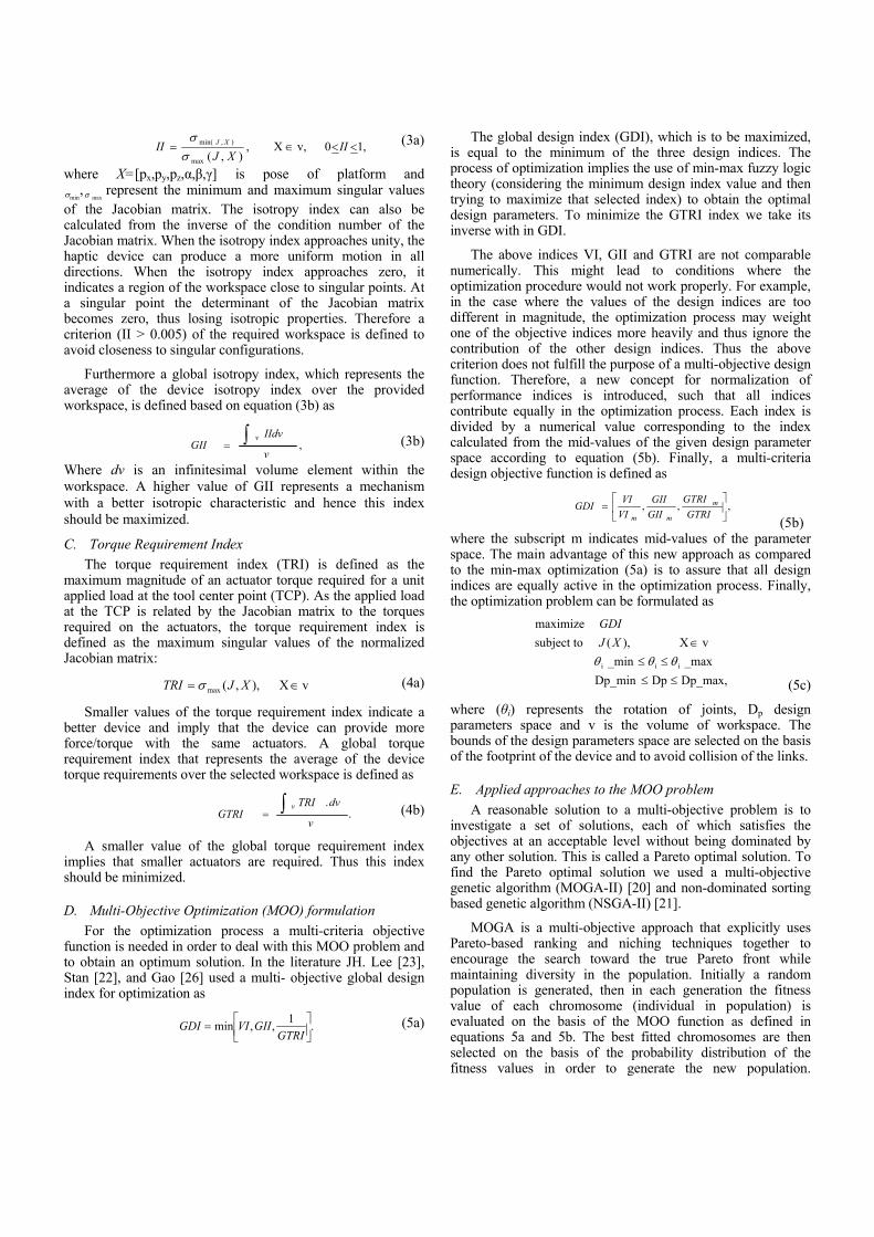
D. Multi-Objective Optimization (MOO) formulation
For the optimization process a multi-criteria objective function is needed in order to deal with this MOO problem and to obtain an optimum solution. In the literature JH. Lee [23], Stan [22], and Gao [26] used a multi- objective global design index for optimization as
.1
,,min
GTRIGIIVIGDI (5a)
The global design index (GDI), which is to be maximized, is equal to the minimum of the three design indices. The process of optimization implies the use of min-max fuzzy logic theory (considering the minimum design index value and then trying to maximize that selected index) to obtain the optimal design parameters. To minimize the GTRI index we take its inverse with in GDI.
The above indices VI, GII and GTRI are not comparable numerically. This might lead to conditions where the optimization procedure would not work properly. For example, in the case where the values of the design indices are too different in magnitude, the optimization process may weight one of the objective indices more heavily and thus ignore the contribution of the other design indices. Thus the above criterion does not fulfill the purpose of a multi-objective design function. Therefore, a new concept for normalization of performance indices is introduced, such that all indices contribute equally in the optimization process. Each index is divided by a numerical value corresponding to the index calculated from the mid-values of the given design parameter space according to equation (5b). Finally, a multi-criteria design objective function is defined as
,,,
GTRI
GTRI
GII
GII
VI
VIGDI m
mm (5b)
where the subscript m indicates mid-values of the parameter space. The main advantage of this new approach as compared to the min-max optimization (5a) is to assure that all design indices are equally active in the optimization process. Finally, the optimization problem can be formulated as
Dp_max,DpDp_min
_max _min
vX ),( subject to
maximize
iii
XJ
GDI
(5c)
where (θi) represents the rotation of joints, Dp design parameters space and v is the volume of workspace. The bounds of the design parameters space are selected on the basis of the footprint of the device and to avoid collision of the links.
E. Applied approaches to the MOO problem
A reasonable solution to a multi-objective problem is to investigate a set of solutions, each of which satisfies the objectives at an acceptable level without being dominated by any other solution. This is called a Pareto optimal solution. To find the Pareto optimal solution we used a multi-objective genetic algorithm (MOGA-II) [20] and non-dominated sorting based genetic algorithm (NSGA-II) [21].
MOGA is a multi-objective approach that explicitly uses Pareto-based ranking and niching techniques together to encourage the search toward the true Pareto front while maintaining diversity in the population. Initially a random population is generated, then in each generation the fitness value of each chromosome (individual in population) is evaluated on the basis of the MOO function as defined in equations 5a and 5b. The best fitted chromosomes are then selected on the basis of the probability distribution of the fitness values in order to generate the new population.

Furthermore, crossover and mutation between the chromosomes are set to achieve the convergence and as well as to search the whole space for Pareto optimal solution. The way MOGA operates to calculate the Pareto optimal solution is described in detail in [32].
The NSGA-II algorithm proposed by Deb et al. [33] is a new version of the NSGA algorithm. NSGA-II incorporates elitism and crowding distance. The population is initialized as usual. Once the population has been initialized, the population is sorted into fronts on the basis of non-domination. The first front is the completely non-dominant set in the current population. The second front is dominated by the individuals in the first front only. Subsequent fronts are defined in the same fashion. Each individual in each front is assigned rank (fitness) values based on the front to which they belong. Individuals in the first front are given a fitness value of 1, individuals in the second are assigned a fitness value of 2, and so on. In addition to fitness values, a new parameter called crowding distance is calculated for each individual. The crowding distance is a measure of how close an individual is to its neighbors. Large average crowding distances will result in better diversity in the population and thus improve the performance of the algorithm when calculating the Pareto optimum. The operation of NSGA-II in calculating the Pareto optimum is described in detail in [33, 34].
Matlab has been used for implementation of these optimization approaches using the parameters specified in Table I.
TABLE I. PARAMETERS USED IN GA DURING OPTIMIZATION
GA Parameters Values Initial population size 100
Maximum No. Generation 50 Crossover rate 0.080
Mutation Rate Non Uniform Mutation
IV. RESULTS AND OPTIMUM SOLUTION EVALUATION
The resulting Pareto front is shown in Figs. 3-5. The Pareto optimal solution obtained from MOGA-II is shown as the dense points in Fig. 3, where the performance of all the indices cannot be improved further without deterioration in some of the others, as seen in Fig.4 and 5.
Figure 3. Pareto optimal solution obtained from the applied approaches for
normalized indices. The solutions obtained from these approaches are
approximately the same. The values of the objective functions versus population and generation calculated using MOGA-II
are given in Fig.5. This figure shows that the volume index (VI) and global isotropy index (GII) increase while the global torque requirement index (GTRI) decreases as the optimization process converges to an optimal solution.
Figure 4. Pareto front of the volume, global isotropy, and torque requirement
(normalized indices).
Figure 5. Values of the objective functions (normalized indices)with
generation resulting from MOGA-II.
The set of optimal structural design parameters corresponding to the Pareto optimal solution is given in Table II.
TABLE II. DESIGN PARAMETERS BOUNDS AND OPTIMAL VALUES
Parameters Min Max Optimal L1 [mm] 130 150 138.7310 L2 [mm] 180 190 180.5852 Rp[mm] 35 55 54.3480 d [mm] 50 55 54.9759
θ32nom [deg] 15 25 24.0784 Volume index, VI - - 0.983
Global isotropy index, GII - - 0.18 Global Torque Req. index,
GTRI - - 3.35
A. Workspace, isotropy and torque requirmrnts plots
The optimal structural design parameters obtained from the optimization process have been used to investigate the performance of the device. Fig. 6 shows the reachable workspace volume resulting of the optimal design. The transparent surface shows the outer boundary of the workspace that can be reached. The required workspace of 50 x 50 x 50 mm can easily be adjusted within this reachable workspace, which is shown in Fig. 6. Thus the device fulfills the initial workspace requirements. The device also fulfills the constant orientation requirements of o
xyzo 40,,40 around all three
axes at the center of workspace.

Figure 6. A 3D illustration of workspace with the optimal design parameters.
In order to visualize the variation of isotropy and torque requirement indices in the optimized workspace (Fig. 6) the TCP is moved in a circular path in the z-y plane with small incremental changes in radius. When the radius reaches the maximum, the TCP is shifted to the next z-y plane with a small increment in the x-direction. Fig. 7 shows that the device has good isotropic behavior around the central position of the workspace and that the isotropy reduces as the TCP moves away from the center. Similarly, the torque requirement is small for unit applied force around the center of the workspace, while it increases as the TCP moves away from the central point (Fig. 8).
Figure 7. Variation of isotropy index in the optimal workspace.
Figure 8. Variation of torque requirement index in the optimal workspace
B. Sensitivity plots
In the design process of the mechanical structure it is important to know how sensitive the device performance is to the changes in design parameters. Thus we made a sensitivity analysis of the performance indices for a variation of design
parameter values within the selected bounds (Table II); during the optimization process using GA approach. We kept track of all the design parameters and performance indices versus population and generation until the solution is converged. Using this data we plotted the performance indices against design parameters to provide the sensitivity analysis presented in Fig 9 to 11.
Based on the GA results, the sensitivity of isotropy index to variations in active link L1 and proximal link L2 is shown in Figure 9a). The 3D surface clearly indicates that keeping similar and not too short active and proximal links lengths result in a better isotropy. The optimization results obtained from the genetic algorithm (table II) agrees with the sensitivity analysis (optimal point within the red surface in plot 9a). Similarly plot b) represents the sensitivity of the global torque requirement index to variations in proximal and actuator link lengths. The plot shows again that similar and not too long proximal and actuator link lengths result in a better structure, (blue region in plot 9b). One important point to note from Fig 9 is the relation between the isotropy index and the torque requirements index. Here, the sensitivity plots show that a device with better “isotropic configuration” also has lower actuator torque requirements.
Figure 9. a)The sensitivity of the GII (upper) and b) GTRI (lower) to
actuator and proximal link dimensions respectively.
The effects of the design parameter d and platform radius RP on isotropy and torque requirements indices are presented in Fig 10. In both cases, increasing the radius, results in better performance. The red region in plot 10a) and blue region in 10b) are corresponding to the optimum results obtained from the genetic algorithm (table II). It is clear that both the parameter d for base actuator placement position and platform radius are important in the design of the device and that the performance is quite sensitive to these parameters.

Figure 10. a) The sensitivity of the GII (upper) and b) GTRI (lower) to radius
platform and base actuators positions.
Figure 11. a) The sensitivity of the GII (upper) and b) GTRI (lower) to base actuators position and top actuator nominal position.
Figure 11(a, b) shows the sensitivity of the isotropy index and torque requirement index as a function of top actuator nominal position and design parameter d respectively. The red spot in the 3-D surface plots shows better performance region for isotropy index which is corresponding to high valve of radius and medium value of angle. This also agrees with the result obtained from the genetic algorithm.
It is concluded from the sensitivity analysis that the selected design parameters play important roles in the device performance, thus should be considered in design optimization. If, for some reason, the choice of parameter values deviates from the optimization result, the sensitivity analysis provides guidance as to how the values maybe selected without deteriorating performance too much. To further understand the result from the genetic algorithm, an additional analysis was made. In this analysis one design parameter at a time was changed around the optimal value while the other five parameters were kept constant at the optimal value. This was repeated for all five design parameters. The trends of performance indices obtained with this approach were approximately same as for the genetic algorithm.
V. CAD MODEL
As a first step of developing a prototype, a CAD model was developed based on the final set of design parameters and sensitivity plots. The developed model is shown in figure 12. The size of the model is 250x250x300 mm. Six Maxon DC motors [35] have been selected. All six motor are fixed at the I-Column, which reduces the moving inertia of the mechanism. A cable transmission mechanism with the pulley was selected to transmit the forces, which make the system more backdrivable. Currently we are working on the development of prototype.
Figure 12. Prototype of the 6 DoF TAU haptic device
CONCLUSION
This paper presents design optimization and sensitivity analysis for a 6-DoF TAU haptic device based on a hybrid kinematic structure. For optimization, the performance indices workspace volume, kinematic isotropy and actuator torque requirements are defined; the latter two indices are based on a normalized Jacobian matrix. The three indices are combined in a multi-criteria objective function and used together with a genetic optimization algorithm. The optimization solution obtained is further investigated by sensitivity analyses against each individual design parameter. For the finally selected mechanism design, simulation shows that the optimal parameter values provide good isotropic properties within the required workspace and that the variation of isotropy and torque requirements is small within workspace. A prototype of this design is currently under development, based on optimal design parameters we obtained from GA and sensitivity plots.

ACKNOWLEDGMENT
This research is supported financially by the Higher Education Commission (HEC) Pakistan and the Machine Design Department of the Royal Institute of Technology (KTH).
REFERENCES [1] M. G. Eriksson, M. Dixon and J. Wikander, “A Haptic VR Milling
Surgery Simulator using high Resolution CT-data”, 14th MMVR conferences in los Angeles, USA, January 2006.
[2] S. Khan, K. Andersson “A design Methodology for Haptic Device,” Presneted in International Conference on Engineering and Design ICED 2011, Denmark, 2011.
[3] C. Gosselin, “Kinematic analysis optimization and programming of parallel robotic manipulators,” Ph.D. Thesis, McGill University, Montreal, 1988.
[4] J.-P. Merlet and D. Daney, “Dimensional synthesis of parallel robots with a guaranteed given accuracy over a specific workspace,” in IEEE International Conference on Robotics and Automation, Barcelona, April 19–22, 2005.
[5] K. Suleman, “A literature review of haptic interfaces,” Technical Report, Royal Institute of Technology-KTH, 2010.
[6] Sensible, Phantom 6-DoF haptic device. Available: http://www.sensable.com/haptic-phantom-premium-6dof.htm
[7] T.H. Massie and J.K. Salisbury, “The PHANToM haptic interfaces: A device for probing virtual objects,” Proc. Of the 1994 ASME int. Mechanical Engineering Exposition and congress, Chicago, Illinois, pp. 295–302.
[8] Haption, Virtouse 6D35-45 6-DoF haptic interface. Available: http://www.haption.com/site/eng/html/materiel.php?item=1
[9] MPB Technologies, Freedom 6S 6-DoF haptic interface. Available:http://www.mpb-technologies.ca/mpbt/mpbt_web_2009/_en/6dof/index.html.
[10] H. Vincent, RA. Oliver, CH. Manuel and RDLT. Gabrial, “Haptic interfaces and devices”, Sensor Review ,vol.24, no. 1, pp.16–29, 2004.
[11] VRLOGIC, 6-DoF Delta Haptic Device. Available: http://www.vrlogic.com/html/6-dof_delta_haptic_device_.html.
[12] Y. Tsumaki, H. Naruse, D. N. Nenchev, and M. Uchiyama, “Design of a compact 6-DoF haptic interface,” in Proceedings of the IEEE International Conference on Robotics & Automation, 1998.
[13] J.M. Sabatera, R.J. Saltarén, R. Aracil “Design, modelling and implementation of a 6 URS parallel haptic device”, Robotics and Autonomous Systems 47 (2004) 1–10.
[14] F. Gosselin, J. P. Martins, “Design of a new parallel haptic device for desktop applications” in Proceedings of the first Eurohaptics Conference and Symposium on Haptic Interfaces for Virtual Environments, IEEE 0-7695-2310-2/05, 2005.
[15] Hongliang Cui, Zhenqi Zhu, Zhongxue Gan, Torgny Brogardh Kinematic analysis and error modeling of TAU parallel robot for real –time control of Tau parallel robot”. Robotics and Computer-Integrated Manufacturing 21 (2005) 497–505.
[16] Zhenqi Zhu, Jinsong Li, Zhongxue Gan, Hui Zhang. “Kinematic and dynamic modelling for real-time control of Tau parallel robot”. Mechanism and Machine Theory 40 (2005) 1051–1067.
[17] A. Aftab, S. Khan, and K. Anderssson, “Kinematics and Dynamics of a novel 6-DoF TAU haptic device”, presented in IEEE International Conference on Mechatronics, ICM 2011 Turkey.
[18] F.hao, JP.Merlet “Multi-criteria optimal design of parallel manipulators based on interval analysis ” Mechanism and machine theory 40 (2005) 157-171, sept 2004.
[19] X.-J. Liu, J. Wang, K.-K. Oh, J. Kim, A new approach to the design of a DELTA robot with a desired workspace, J. Intel. Robot. Syst. 39 (2) (2004) 209–225.
[20] T. Murata and H. Ishibuchi, “MOGA: multi-objective genetic algorithms,” in Proceedings of the 1995 IEEE international conference on evolutionary computation, Perth, Australia, Dec. 1995.
[21] K. Deb, A. Pratap, S. Agarwal, T. Meyarivan, “A fast and elitist multiobjective genetic algorithm: NSGA-II,” IEEE Trans. Of Evol. Compution, vol. 6, no. 2, pp. 182–97, 2002.
[22] S. D. Stan, M. Vistrian, B. Radu, R. Calin, B. sorin, “ Optimal link design of a six degree of freedom micro parallel robot based on workspace analysis” 24th international Symposium on Automation & Robotics in Construction (ISARC 2007.)
[23] J.H.Lee, K.S. Eom, B.J Yi, I.H. Suh, “Design of a new-6DoF Parallel haptic device” proceeding of the IEEE international.
[24] Yoon-Kwon Hwang, null Jung-Won Yoon, null Je-Ha Ryu, "The Optimum Design of a 6-DoF Parallel Manipulator with Large Orientation Workspace," sice, pp.1255–1259, 2006 SICE-ICASE International Joint Conference, 2006.
[25] A.Guigue, M. Ahmadi, R. Langlois and MJ. Hayes, “Pareto Optimality and Multiobjective Trajectory Planning for a 7-DoF Redundant Manipulator”, IEEE Transaction of Robotics, Vol 26, 6 Pages: 1094 – 1099, 2010
[26] G. Zhen, D. Zhang and G. Yunjian, “Design optimization of a spatial six degree of freedom parallel manipulator based on artificial intelligence approaches,” Journal of Robotics and Computer-Integrated Manufacturing, vol. 26, pp. 180–189, 2010.
[27] ADAMS, www.mscsoftware.com.
[28] L. J. Stocco, S.E. Salcudean, and F. Sassani, “Matrix normalization for optimal robot design,” IEEE International Conference on Robotics and Automation, Leuven, Belgium, 1998.
[29] M. Tandridge, J. Angeles and F. Ranjbaran “The characteristic point and the characteristic length of robotics manipulators,” in Proc. ASME 22nd Biennial Conf. Robot. Spatial Mech. Syst., Sept 1992.
[30] O. Ma and J. Angeles “Optimum architecture design of platform manipulators,” in Proc. IEEE International Conference of Advance Robot., 1991.
[31] Y. Wang, W.S. Newman, and R. Stoughton, “Workspace analysis of the ParaDex Robot: A novel, closed-chain, kinematically-redundant manipulator,” IEEE International Conference on Robotics & Automation, vol. 3, pp. 2392–2397, 2000.
[32] Konak, D. W. Coit, A. E. Smith, “Multi-objective optimization using genetic algorithms: A tutorial,” Journal of Reliability Engineering and System Safety, vol. 91, pp. 992–1007, 2006.
[33] K. Deb, S. Agrawal, A. Pratap, and T. Meyarivan. “A fast and elitist multiobjective genetic algorithm: NSGA-II,” IEEE Trans. Evolutionary Computation, vol. 6, no. 2, pp. 182–197, 2002.
[34] E. ZitZler, K. Deb, and L. Thiele, “Comparison of multiobjective evolutionary algorithms: Empirical results. IEEE Trans. Evolutionary Computation, vol. 8, no. 2, pp. 173–95, 2008.
[35] Maxon Motor “High precision drives and system- program 09/10”. Page 79. www.maxonmotor.com