Embed Size (px)
Citation preview

Specialty Plants: Haptics
Quanser's High Definition Haptic Device (HD2)
User Manual

HD2 User Manual
Table of Contents1. General Description/Overview............................................................................................4
1.1. Hardware System Presentation....................................................................................41.2. System Software Presentation......................................................................................5
2. HD2 System Components....................................................................................................72.1. Component Nomenclature...........................................................................................72.2. Component Description...............................................................................................9
2.2.1. Aluminum Arm and End-Effector Handle (Components #3 And #4).................92.2.2. DC Motor ...........................................................................................................92.2.3. Optical Encoders .................................................................................................92.2.4. Counterbalances (Component #7)......................................................................102.2.5. Analog I/O Switch (Component #23)................................................................102.2.6. LEDs (Component #24 to #28)..........................................................................102.2.7. Q8 HIL Board.....................................................................................................112.2.8. Q8-To-Amplifier Adapter Board.......................................................................122.2.9. Customized PC...................................................................................................122.2.10. Emergency Stop Push Button...........................................................................122.2.11. Supplied Cables................................................................................................13
3. Cabling of the HD2 ...........................................................................................................143.1. Cabling Procedure......................................................................................................14
3.1.1. HD2 –PC Interface ............................................................................................143.1.2. HD2 – E-stop .....................................................................................................143.1.3. Inside PC : Adapter Box – Q8 Interface............................................................143.1.4. HD2 – Pedal Interface (Optional)......................................................................15
3.2. Signal Connection Nomenclature..............................................................................163.2.1. Q8 Digital Input And Output (DIO) Connection Table.....................................163.2.2. Q8 Analog Input And Output (AIO) Connection Table....................................163.2.3. HD2 Amplifier-To-Motor Connection Table.....................................................17
4. System Parameters.............................................................................................................195. Kinematics.........................................................................................................................216. Motor and Encoder Assignment........................................................................................227. Calibration Procedure........................................................................................................238. Supplied Files....................................................................................................................25
8.1. File Description..........................................................................................................258.1.1. HD2 Interface Block..........................................................................................258.1.2. Position Control Example: Fixed Point..............................................................268.1.3. Virtual Reality Example: Sphere........................................................................288.1.4. HD2_Cube.mdl...................................................................................................30
9. References..........................................................................................................................31Appendix A. HD2 Software Subsystems Description...........................................................32
Document Number: 560 Revision: 01 Page: i
HD2 User Manual
9.1. HD2_Interface.mdl....................................................................................................329.1.1. Angle Calculator Block......................................................................................329.1.2. N-m to Amps Block...........................................................................................329.1.3. Joint Torque to Motor Torque Block.................................................................339.1.4. Jacobian Block...................................................................................................339.1.5. Two-Link Planar Arm Forward Kinematics and Jacobian Block......................349.1.6. Angle Calculator Block......................................................................................35
List of FiguresFigure 1: HD2 Front View.......................................................................................................4Figure 2: HD2 Front View.......................................................................................................8Figure 3: HD2 Back Top View................................................................................................8Figure 4: HD2 Back Bottom View..........................................................................................8Figure 5: HD2 Encoders Internal Wiring..............................................................................10Figure 6: Q8 HIL Board........................................................................................................11Figure 7: Q8-To-Amplifier Adapter Box - Out of PC view..................................................12Figure 8: E-Stop Push Button................................................................................................12Figure 9: Connection of the Q8 board and the Q8-To-Amplifier Adapter Box....................15Figure 10: HD2 Motor Number Assignment.........................................................................18Figure 11: HD2 Co-ordinate System....................................................................................21Figure 12: HD2 Motor Number Assignment.........................................................................22Figure 13: HD2 In Home Position.........................................................................................23Figure 14: HD2 and sphere virtual reality window...............................................................28
List of TablesTable 1 HD2 Component Nomenclature.................................................................................7Table 2 HD2 Arm Characteristics...........................................................................................9Table 3 HD2 LED Description..............................................................................................11Table 4: HD2 Cable Set Description.....................................................................................13Table 5 Q8 DIO Connection Nomenclature..........................................................................16Table 6 Q8 AIO Connection Nomenclature..........................................................................17Table 7 Amplifier-To-Motor Connection Nomenclature.....................................................17Table 8 HD2 Specifications at Home Position. Refer to Figure 11 for the System Coordinate Frame..................................................................................................................20Table 9: Files Supplied With the HD2 System
Document Number: 560 Revision: 01 Page: ii

HD2 User Manual
CAUTION / NOTICE This product is intended for experienced engineers only! The user is solely responsible for the implementation of the controller! Quanser is not responsible for any material or bodily damage that ensues from the use of this equipment.
All software supplied is only to be considered a sample and should not be used on a regular basis. The users should write their own control software.
Read this manual before operating the supplied system.How to contact Quanser Consulting:
905-940-3575 Telephone
905-940-3576 Facsimile
119 Spy CourtMarkham, ONCanada L3R 5H6
http://www.quanser.com Web
mailto://[email protected] General information
Disclaimer
While every effort has been made to ensure the accuracy and completeness of all information in this document, Quanser, Inc. assumes no liability to any party for any loss or damage caused by errors or omissions or by statements of any kind in this document, its updates, supplements, or special editions. Quanser, Inc. further assumes no liability arising out of the application or use of any product or system described herein; nor any liability for incidental or consequential damages arising from the use of this document. Quanser, Inc. disclaims all warranties regarding the information contained herein, whether expressed, implied or statutory, including implied warranties of merchantability or fitness for a particular purpose. Quanser Inc. reserves the right to make changes to this document or to the products described herein without further notice.
Document Number: 560 Revision: 02 Page: 3
HD2 User Manual
1. General Description/Overview
1.1. Hardware System Presentation
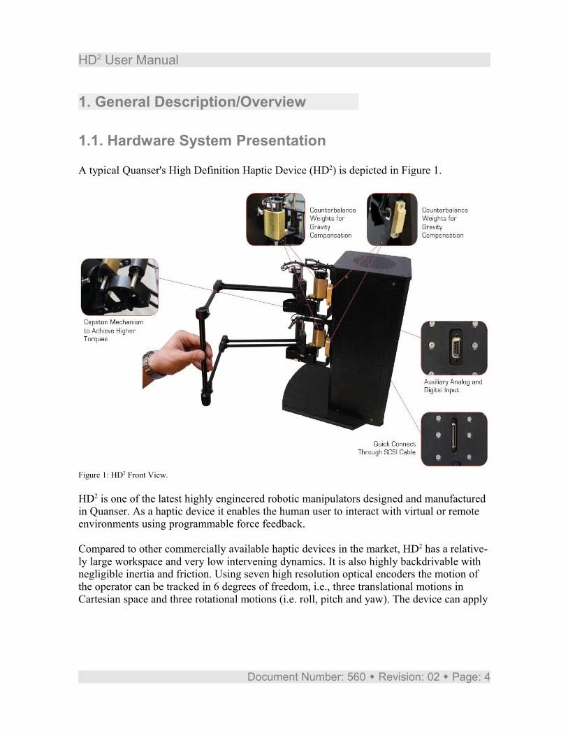
A typical Quanser's High Definition Haptic Device (HD2) is depicted in Figure 1.
HD2 is one of the latest highly engineered robotic manipulators designed and manufactured in Quanser. As a haptic device it enables the human user to interact with virtual or remote environments using programmable force feedback.
Compared to other commercially available haptic devices in the market, HD2 has a relative-ly large workspace and very low intervening dynamics. It is also highly backdrivable with negligible inertia and friction. Using seven high resolution optical encoders the motion of the operator can be tracked in 6 degrees of freedom, i.e., three translational motions in Cartesian space and three rotational motions (i.e. roll, pitch and yaw). The device can apply
Document Number: 560 Revision: 02 Page: 4
Figure 1: HD2 Front View.

HD2 User Manual
force feedback to the user in 5 degrees of freedom.
HD2 model consists of double two-link planar arm configurations connected in parallel to a rod using two universal joints (U-joints) to form the end-effector of the device. Each two-link planar arm solely is actuated by two capstan-drive DC motors using a parallel mecha-nism which lets the motors be mounted at the base of the arm. As a result, the displayed in-ertia to the operator is highly reduced while the rigidity of the structure is maintained. A third DC motor is mounted at the waist of each two-link planar arm providing it with a third degree of freedom (pitch). Made of lightweight materials, HD2 equivalent weight over its entire workspace is further minimized by two adjustable brass counterbalances mounted on one of the two motors at each base . This state-of-the-art device is equipped with 6 built-in high-performance linear current amplifiers (i.e. Quanser LCAM devices) which along with the use of parallel mechanisms and capstan drive actuators make it possible for the device to provide the user with stiffness coefficients as high as 20,000 N/m.
A user push pedal is provided with the device as a digital input for switching applications. For instance, it can be used as a clutch to temporarily deactivate the HD2 system in situa-tions such as tele-operation where the user has reached the threshold operating range and needs to disconnect the master robot from the slave robot and move the end-effector to a new position to continue operation. The system is controlled via a PC using Quanser’s lead-ing-edge Q8 superior-performance hardware-in-the-loop (HIL) control board.
1.2. System Software PresentationThe HD2 system is supplied with Quanser’s flexible QuaRC software and application examples to perform real-time control using MATLAB/Simulink. For details regarding QuaRC, Quanser's real-time data acquisition and control software, please refer to Refer-ences [2] and [3]. It is assumed that you are familiar with QuaRC and its operation before you use the HD2.
The complete kinematic and dynamic modeling of the system as well as the system parame-ters are provided to streamline the implementation of the control scheme of your choice. The open architecture design of the system allows users to develop any control algorithm they desire.
With the QuaRC HIL API, users can develop their own controllers on the platform and environment of their choice (e.g. C, C++, Java, .NET, MATLAB). For more information, see the QuaRC External Interfaces section in Reference [2].
Document Number: 560 Revision: 02 Page: 5
HD2 User Manual
2. HD2 System Components
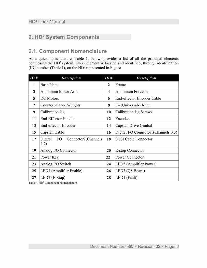
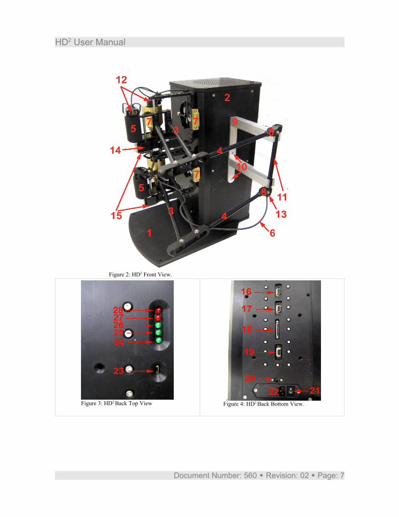
2.1. Component NomenclatureAs a quick nomenclature, Table 1, below, provides a list of all the principal elements composing the HD2 system. Every element is located and identified, through identification (ID) number (Table 1), on the HD2 represented in Figures
ID # Description ID # Description
1 Base Plate 2 Frame
3 Aluminum Motor Arm 4 Aluminum Forearm
5 DC Motors 6 End-effector Encoder Cable
7 Counterbalance Weights 8 U- (Universal-) Joint
9 Calibration Jig 10 Calibration Jig Screws
11 End-Effector Handle 12 Encoders
13 End-effector Encoder 14 Capstan Drive Gimbal
15 Capstan Cable 16 Digital I/O Connector1(Channels 0:3)
17 Digital I/O Connector2(Channels 4:7)
18 SCSI Cable Connector
19 Analog I/O Connector 20 E-stop Connector
21 Power Key 22 Power Connector
23 Analog I/O Switch 24 LED5 (Amplifier Power)
25 LED4 (Amplifier Enable) 26 LED3 (Q8 Board)
27 LED2 (E-Stop) 28 LED1 (Fault)Table 1 HD2 Component Nomenclature.
Document Number: 560 Revision: 02 Page: 6
HD2 User Manual
Document Number: 560 Revision: 02 Page: 7
Figure 2: HD2 Front View.
Figure 3: HD2 Back Top View Figure 4: HD2 Back Bottom View.
HD2 User Manual
2.2. Component DescriptionThis Section provides a description of the individual elements comprising the full HD2 system.
2.2.1. Aluminum Arm and End-Effector Handle (Components #3 And #4)The system consists of seven arms configured into two parallel planar arms. They are made out of Aluminum tubes of uniform cross section. For each planar arm two aluminum rods are used to form the motor arm and one aluminum rod makes the forearm. Another alu-minum tube is used for the end-effector handle.
Description Value UnitMotor Arm Length 0.280 m
Forearm Length 0.290 m
End-Effector Handle Length 0.175 m
Device Total Mass 22 kgTable 2 HD2 Arm Characteristics
2.2.2. DC Motor The HD2 unit incorporates 6 custom made Faulhaber Coreless DC Motor (3863V006), as represented in Figures 6 and 7 by component #9. This model is a high efficiency low induc-tance motor resulting in a much faster response than a conventional DC motor.
CAUTION: High Frequency signals applied to a motor will eventually damage the gearbox and/or the motor brushes. The most likely source for high frequency noise is derivative feedback. If the derivative gain is too high, a noisy voltage will be fed into the motor. To protect your motor, you should always band limit your signal (especially derivative feed-back) to a value of 50Hz.
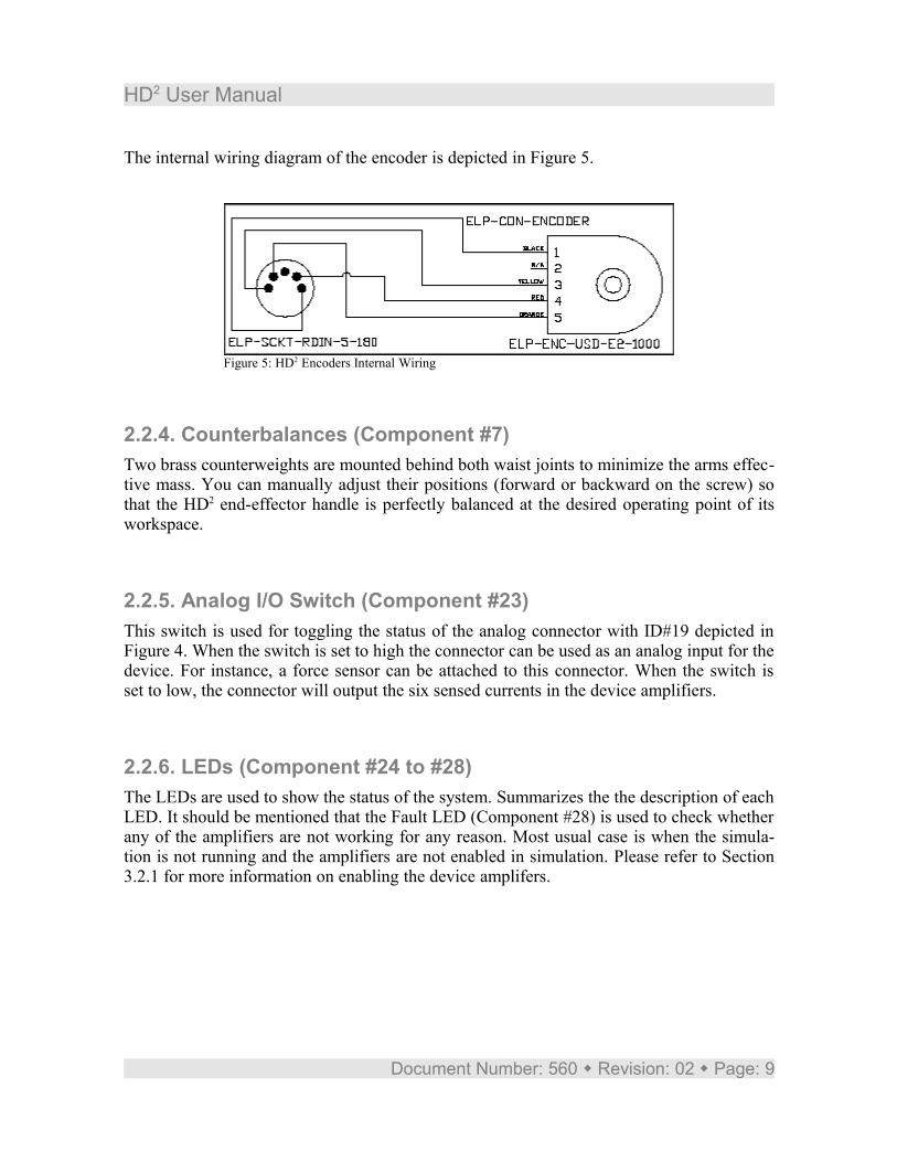
2.2.3. Optical Encoders Digital position measurement of all six actuated joints and the rotation of the device end-ef-fector is obtained by using seven high-resolution quadrature optical encoders. Six of the op-tical encoders are directly mounted on the rear of each one of the six motors. The motor en-coder has a resolution of 1000 lines per revolution. In quadrature mode this gives 4000 counts per full rotation of the encoder shaft.
Document Number: 560 Revision: 02 Page: 8
HD2 User Manual
The internal wiring diagram of the encoder is depicted in Figure 5.
2.2.4. Counterbalances (Component #7)Two brass counterweights are mounted behind both waist joints to minimize the arms effec-tive mass. You can manually adjust their positions (forward or backward on the screw) so that the HD2 end-effector handle is perfectly balanced at the desired operating point of its workspace.
2.2.5. Analog I/O Switch (Component #23)This switch is used for toggling the status of the analog connector with ID#19 depicted in Figure 4. When the switch is set to high the connector can be used as an analog input for the device. For instance, a force sensor can be attached to this connector. When the switch is set to low, the connector will output the six sensed currents in the device amplifiers.
2.2.6. LEDs (Component #24 to #28)The LEDs are used to show the status of the system. Summarizes the the description of each LED. It should be mentioned that the Fault LED (Component #28) is used to check whether any of the amplifiers are not working for any reason. Most usual case is when the simula-tion is not running and the amplifiers are not enabled in simulation. Please refer to Section 3.2.1 for more information on enabling the device amplifers.
Document Number: 560 Revision: 02 Page: 9
Figure 5: HD2 Encoders Internal Wiring
HD2 User Manual
LED ID Number Description#28 (Fault) It is On when the simulation is not running. It is Off when the
simulation is running. Contact Quanser's Customer Service in case this LED is On during the Simulation.
#27 (E-stop) It is On when the E-stop is pressed and has deactivated the amplifiers. It is Off when the E-stop is depressed.
#26 (Q8) It is On when the Q8 board is connected to the HD2 unit through the SCSI cable.
#25 (Enable) It is On whenever the amplifiers are enabled through the digital channels 9 and 10 in the simulation. It is Off when the amplifiers are not enabled. Refer to Section 3.2.1 for further information.
#24 (Amplifier Power)
It is an optional trouble-shooting LED for systems that are equipped with more than six amplifiers
Table 3 HD2 LED Description
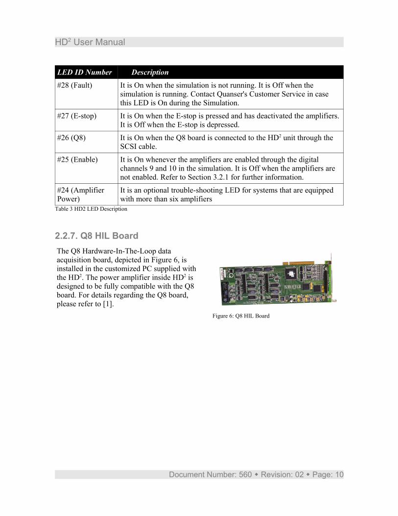
2.2.7. Q8 HIL BoardThe Q8 Hardware-In-The-Loop data acquisition board, depicted in Figure 6, is installed in the customized PC supplied with the HD2. The power amplifier inside HD2 is designed to be fully compatible with the Q8 board. For details regarding the Q8 board, please refer to [1].
Document Number: 560 Revision: 02 Page: 10
Figure 6: Q8 HIL Board
HD2 User Manual
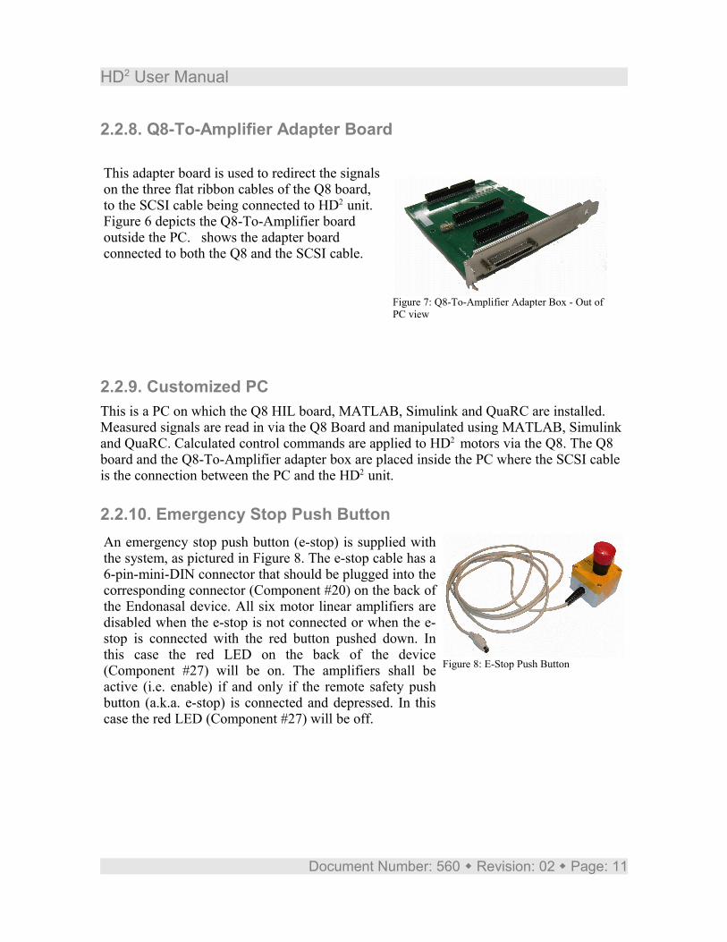
2.2.8. Q8-To-Amplifier Adapter Board
This adapter board is used to redirect the signals on the three flat ribbon cables of the Q8 board, to the SCSI cable being connected to HD2 unit. Figure 6 depicts the Q8-To-Amplifier board outside the PC. shows the adapter board connected to both the Q8 and the SCSI cable.
2.2.9. Customized PCThis is a PC on which the Q8 HIL board, MATLAB, Simulink and QuaRC are installed. Measured signals are read in via the Q8 Board and manipulated using MATLAB, Simulink and QuaRC. Calculated control commands are applied to HD2 motors via the Q8. The Q8 board and the Q8-To-Amplifier adapter box are placed inside the PC where the SCSI cable is the connection between the PC and the HD2 unit.
2.2.10. Emergency Stop Push ButtonAn emergency stop push button (e-stop) is supplied with the system, as pictured in Figure 8. The e-stop cable has a 6-pin-mini-DIN connector that should be plugged into the corresponding connector (Component #20) on the back of the Endonasal device. All six motor linear amplifiers are disabled when the e-stop is not connected or when the e-stop is connected with the red button pushed down. In this case the red LED on the back of the device (Component #27) will be on. The amplifiers shall be active (i.e. enable) if and only if the remote safety push button (a.k.a. e-stop) is connected and depressed. In this case the red LED (Component #27) will be off.
Document Number: 560 Revision: 02 Page: 11
Figure 7: Q8-To-Amplifier Adapter Box - Out of PC view
Figure 8: E-Stop Push Button
HD2 User Manual
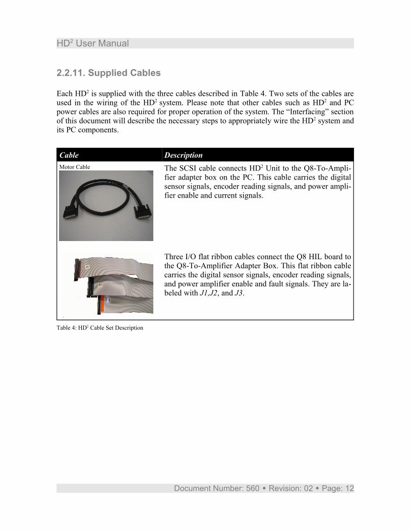
2.2.11. Supplied Cables
Each HD2 is supplied with the three cables described in Table 4. Two sets of the cables are used in the wiring of the HD2 system. Please note that other cables such as HD2 and PC power cables are also required for proper operation of the system. The “Interfacing” section of this document will describe the necessary steps to appropriately wire the HD2 system and its PC components.
Cable DescriptionMotor Cable The SCSI cable connects HD2 Unit to the Q8-To-Ampli-
fier adapter box on the PC. This cable carries the digital sensor signals, encoder reading signals, and power ampli-fier enable and current signals.
Three I/O flat ribbon cables connect the Q8 HIL board to the Q8-To-Amplifier Adapter Box. This flat ribbon cable carries the digital sensor signals, encoder reading signals, and power amplifier enable and fault signals. They are la-beled with J1,J2, and J3.
Table 4: HD2 Cable Set Description
Document Number: 560 Revision: 02 Page: 12
HD2 User Manual
3. Cabling of the HD2 This section describes the wiring steps required to appropriately interface the HD2 unit to the customized (controller) PC.
3.1. Cabling ProcedureThe overall interface between the HD2 and the PC is divided into three sub-interfaces as described below. The following hardware, accompanying the HD2 , is assumed:
● Data Acquisition Card: Quanser's Q8 HIL board.● Signal Interface Board: Quanser's Q8-To-Amplifier Adapter Box.● Enable Tool Quanser's E-stop Push Button
CAUTION
Perform all connections with the PC and HD2 units turned off.
3.1.1. HD2 –PC Interface The HD2 interface consists of the wiring between the SCSI connector on the back side of the device and the PC. Figure 4 depicts the SCSI connector (Component #18) on the back side of the HD2 unit.
3.1.2. HD2 – E-stop As described in Section 2.2.10 the E-stop button is using a 6-pin-mini-DIN connector which should be connected to the corresponding connector (Component #20 in Figure 4) on the back side of the HD2 unit.
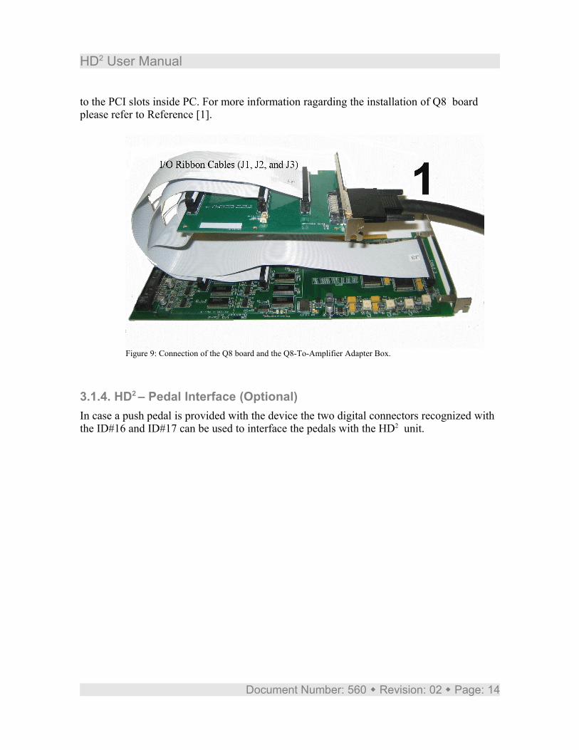
3.1.3. Inside PC : Adapter Box – Q8 InterfaceConnect the three Q8 flat ribbon cables from the Q8 HIL board to the appropriate connectors on the Q8-To-Amplifier Adapter Box as depicted in Figure 9. Make sure that the ribbon cables labeled with J1, J2, and J3 are connected to their related connectors J1, J2, and J3 on the Adapter Box, respectively. Both Q8 board and the Adapter Box are connected
Document Number: 560 Revision: 02 Page: 13
HD2 User Manual
to the PCI slots inside PC. For more information ragarding the installation of Q8 board please refer to Reference [1].
3.1.4. HD2 – Pedal Interface (Optional)In case a push pedal is provided with the device the two digital connectors recognized with the ID#16 and ID#17 can be used to interface the pedals with the HD2 unit.
Document Number: 560 Revision: 02 Page: 14
Figure 9: Connection of the Q8 board and the Q8-To-Amplifier Adapter Box.
HD2 User Manual
3.2. Signal Connection NomenclatureThis Section details the connections actually attained with the cabling described above.
3.2.1. Q8 Digital Input And Output (DIO) Connection TableTable 5 details the Digital Input and Output (DIO) connections between the Q8 and HD2
attained through the Q8-To-Amplifier Adapter board.
Q8 DIO Channel
Signal Func-tion
High:1
Low:0
DIO #0 to #7 User Defined Signals
DI #8 The fault LED(Component #28) state Input Fault No Fault
DO #9 HD2 Amplifier General Enable Signal Output Disable Enable
DO #10 HD2 Amplifier General Enable Signal Output Enable Disable
DI #11 E-stop State Input Pressed Not Pressed
Table 5 Q8 DIO Connection Nomenclature
Table 5 summarizes, amongst others, the enable features of the linear current amplifiers. The E-Stop state is available to be read on the Q8 from DIO #11. The HD2 amplifiers can be enabled by setting the digital channel 9 to zero and digital channel 10 to one. Lastly, more switches can be implemented and defined by the user on the digital lines from channels #0 to #7.
3.2.2. Q8 Analog Input And Output (AIO) Connection TableTable 6 details the Analog Input and Output (AIO) connections between the Q8 and the amplifiers attained through the Q8-To-Amplifier Adapter box.
Document Number: 560 Revision: 02 Page: 15
HD2 User Manual
Amplifier ID Q8 AO Channel:Amplifier Command
Q8 AI Channel:Current Measurement
Amp #0 AO #0 AI #0
Amp #1 AO #1 AI #1
Amp #2 AO #2 AI #2
Amp #3 AO #3 AI #3
Amp #4 AO #4 AI #4
Amp #5 AO #5 AI #5Table 6 Q8 AIO Connection Nomenclature
The command to each motor current is applied from six of the Q8 Analog Outputs (AO's). As expressed in Table 6, the six motor current commands are set by the AO from channels 0 to 5. Each amplifier gain is internally set to 1/(2.41) A/V. The current in each motor can be individually monitored using six of the Q8 Analog Inputs (AI's). The six motor currents are available to be read on the AI from channels 0 to 5. The gain of the current sensor is 0.5 V/A.
Note:Note that a positive voltage (or current) applied to one of the six DC motor inputs results in a Counterclockwise (CCW) rotation when facing the motor output shaft and vice-versa.
3.2.3. HD2 Amplifier-To-Motor Connection TableTable 7 details the connections between both HD2 power amplifiers and the HD2 six motors (or axes) attained through both "Motor" and "Encoder" cables.
Amplifier ID Motor Location(Facing The Robot)
Q8 Encoder Input Channel
Motor/Joint IDUsed in Modeling
Amp #0 Top-Left EI #0 Shoulder: Motor #1
Amp #1 Top-Middle EI #1 Shoulder: Motor #2
Amp #2 Top-Right EI #2 Base: Motor #3
Amp #3 Bottom-Left EI #3 Shoulder: Motor #4
Amp #0 Bottom-Middle EI #4 Shoulder: Motor #5
Amp #1 Bottom-right EI #5 Base: Motor #6Table 7 Amplifier-To-Motor Connection Nomenclature
Document Number: 560 Revision: 02 Page: 16
HD2 User Manual
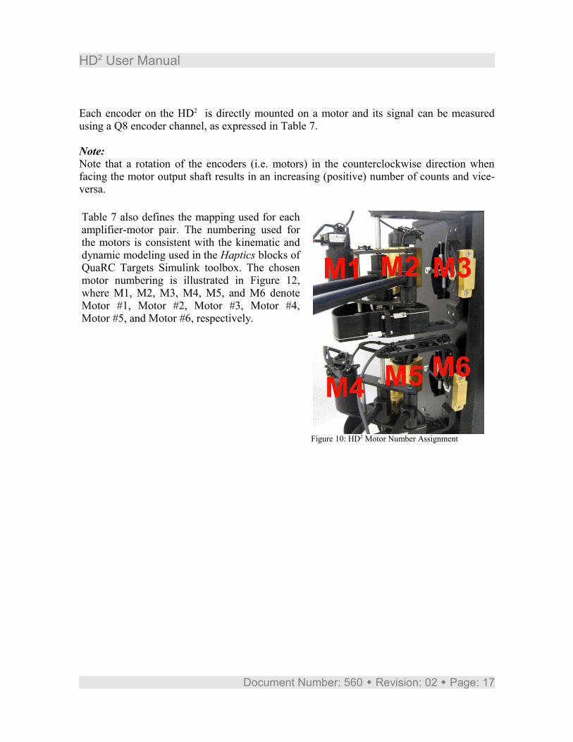
Each encoder on the HD2 is directly mounted on a motor and its signal can be measured using a Q8 encoder channel, as expressed in Table 7.
Note:Note that a rotation of the encoders (i.e. motors) in the counterclockwise direction when facing the motor output shaft results in an increasing (positive) number of counts and vice-versa.
Table 7 also defines the mapping used for each amplifier-motor pair. The numbering used for the motors is consistent with the kinematic and dynamic modeling used in the Haptics blocks of QuaRC Targets Simulink toolbox. The chosen motor numbering is illustrated in Figure 12, where M1, M2, M3, M4, M5, and M6 denote Motor #1, Motor #2, Motor #3, Motor #4, Motor #5, and Motor #6, respectively.
Document Number: 560 Revision: 02 Page: 17
Figure 10: HD2 Motor Number Assignment
HD2 User Manual
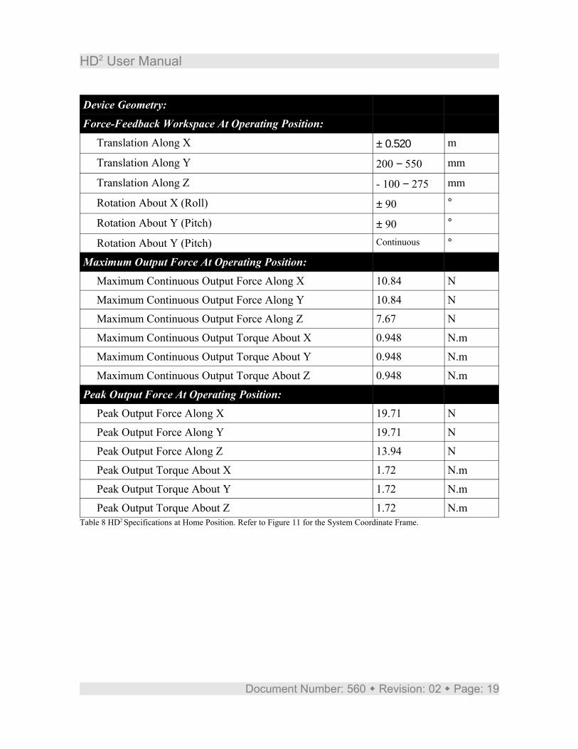
4. System ParametersThe specifications on the HD2 model parameters are given in Table 8.
Description Value UnitDC Motors (Each)
Motor Power Rating 90 W
Motor Torque Constant 0.115 N.m/A
Motor Peak Current 5 A
Linear Current Amplifiers (Each Channel):Linear Amplifier Peak Power 140 W
Linear Amplifier Maximum Continuous Current 3 A
Linear Amplifier Peak Current 5 A
Linear Amplifier Gain 1/(2.41) A/V
Build-In Power Supplies (Each):Power Supply Power 315.9 W
Power Supply Voltage 27 VDC
Optical Encoders (Each):Encoder Line Count 1,000 lines/rev
Encoder Resolution (In Quadrature) 4,000 counts/rev
Encoder Sensitivity (In Quadrature) 0.0015 °/count
Encoder Type TTL
Encoder Signals A, B, Index
Current Sense:Current Sense Calibration At ±10% 0.5 V/A
Device Geometry:Motor Arm Length 0.280 m
Forearm Length 0.290 m
End-Effector Arm Length 0.175 m
Document Number: 560 Revision: 02 Page: 18
HD2 User Manual
Device Geometry:Force-Feedback Workspace At Operating Position:
Translation Along X ± 0.520 m
Translation Along Y 200 − 550 mm
Translation Along Z - 100 − 275 mm
Rotation About X (Roll) ± 90 °
Rotation About Y (Pitch) ± 90 °
Rotation About Y (Pitch) Continuous °
Maximum Output Force At Operating Position:Maximum Continuous Output Force Along X 10.84 N
Maximum Continuous Output Force Along Y 10.84 N
Maximum Continuous Output Force Along Z 7.67 N
Maximum Continuous Output Torque About X 0.948 N.m
Maximum Continuous Output Torque About Y 0.948 N.m
Maximum Continuous Output Torque About Z 0.948 N.m
Peak Output Force At Operating Position:Peak Output Force Along X 19.71 N
Peak Output Force Along Y 19.71 N
Peak Output Force Along Z 13.94 N
Peak Output Torque About X 1.72 N.m
Peak Output Torque About Y 1.72 N.m
Peak Output Torque About Z 1.72 N.mTable 8 HD2 Specifications at Home Position. Refer to Figure 11 for the System Coordinate Frame.
Document Number: 560 Revision: 02 Page: 19
HD2 User Manual
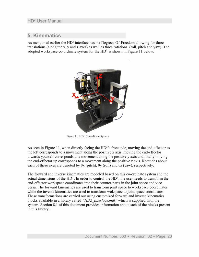
5. KinematicsAs mentioned earlier the HD2 interface has six Degrees-Of-Freedom allowing for three translations (along the x, y and z axes) as well as three rotations (roll, pitch and yaw). The adopted workspace co-ordinate system for the HD2 is shown in Figure 11 below:
As seen in Figure 11, when directly facing the HD2 's front side, moving the end-effector to the left corresponds to a movement along the positive x axis, moving the end-effector towards yourself corresponds to a movement along the positive y axis and finally moving the end-effector up corresponds to a movement along the positive z axis. Rotations about each of these axes are denoted by θx (pitch), θy (roll) and θz (yaw), respectively.
The forward and inverse kinematics are modeled based on this co-ordinate system and the actual dimensions of the HD2 . In order to control the HD2 , the user needs to transform the end-effector workspace coordinates into their counter-parts in the joint space and vice versa. The forward kinematics are used to transform joint space to workspace coordinates while the inverse kinematics are used to transform wokspace to joint space coordinates. These transformations are carried out using customized forward and inverse kinematics blocks available in a library called “HD2_Interface.mdl” which is supplied with the system. Section 8.1 of this document provides information about each of the blocks present in this library.
Document Number: 560 Revision: 02 Page: 20
Figure 11: HD2 Co-ordinate System
HD2 User Manual
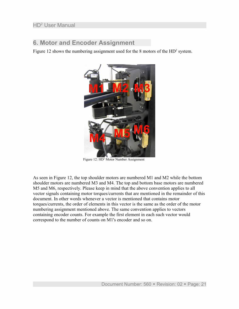
6. Motor and Encoder AssignmentFigure 12 shows the numbering assignment used for the 8 motors of the HD2 system.
As seen in Figure 12, the top shoulder motors are numbered M1 and M2 while the bottom shoulder motors are numbered M3 and M4. The top and bottom base motors are numbered M5 and M6, respectively. Please keep in mind that the above convention applies to all vector signals containing motor torques/currents that are mentioned in the remainder of this document. In other words whenever a vector is mentioned that contains motor torques/currents, the order of elements in this vector is the same as the order of the motor numbering assignment mentioned above. The same convention applies to vectors containing encoder counts. For example the first element in each such vector would correspond to the number of counts on M1's encoder and so on.
Document Number: 560 Revision: 02 Page: 21
Figure 12: HD2 Motor Number Assignment
HD2 User Manual
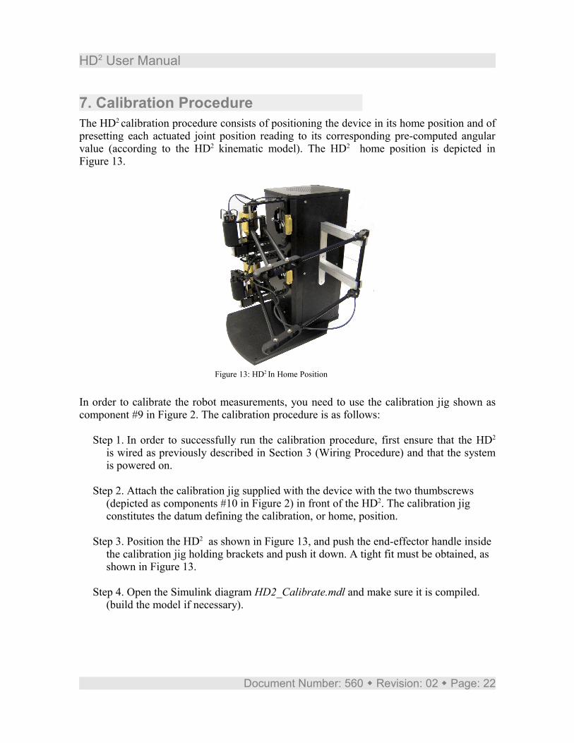
7. Calibration ProcedureThe HD2 calibration procedure consists of positioning the device in its home position and of presetting each actuated joint position reading to its corresponding pre-computed angular value (according to the HD2 kinematic model). The HD2 home position is depicted in Figure 13.
In order to calibrate the robot measurements, you need to use the calibration jig shown as component #9 in Figure 2. The calibration procedure is as follows:
Step 1. In order to successfully run the calibration procedure, first ensure that the HD2
is wired as previously described in Section 3 (Wiring Procedure) and that the system is powered on.
Step 2. Attach the calibration jig supplied with the device with the two thumbscrews (depicted as components #10 in Figure 2) in front of the HD2. The calibration jig constitutes the datum defining the calibration, or home, position.
Step 3. Position the HD2 as shown in Figure 13, and push the end-effector handle inside the calibration jig holding brackets and push it down. A tight fit must be obtained, as shown in Figure 13.
Step 4. Open the Simulink diagram HD2_Calibrate.mdl and make sure it is compiled. (build the model if necessary).
Document Number: 560 Revision: 02 Page: 22
Figure 13: HD2 In Home Position

HD2 User Manual
Caution: If your PC has more than one Q8 board, you may have to specify the board (e.g. 0 or 1) before doing the calibration.
Step 5. With the end-effector inside the calibration jig run the model for a short time (half a second for instance). Make sure that all the encoder readings are set to zero in the Display block)
Step 6. The HD2 is now calibrated and you can now remove the calibration jig and close the Simulink diagram. Once calibrated, you do not need to re-initialize the encoder counters unless you turn off PC. The Q8 encoder counters keep counting the encoder pulses even after a program has been stopped.
Caution: All subsequent programs should not re-load any number of counts into the encoder counters. If any subsequent program resets the number of counts, the HD2
position you start the program at will be considered the zero position and the system will be mis-calibrated (unless you started at the home position).
Document Number: 560 Revision: 02 Page: 23
HD2 User Manual
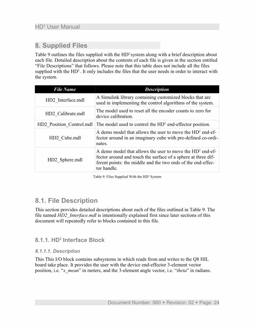
8. Supplied FilesTable 9 outlines the files supplied with the HD2 system along with a brief description about each file. Detailed description about the contents of each file is given in the section entitled “File Descriptions” that follows. Please note that this table does not include all the files supplied with the HD2 . It only includes the files that the user needs in order to interact with the system.
File Name Description
HD2_Interface.mdl A Simulink library containing customized blocks that are used in implementing the control algorithms of the system.
HD2_Calibrate.mdl The model used to reset all the encoder counts to zero for device calibration.
HD2_Position_Control.mdl The model used to control the HD2 end-effector position.
HD2_Cube.mdlA demo model that allows the user to move the HD2 end-ef-fector around in an imaginary cube with pre-defined co-ordi-nates.
HD2_Sphere.mdl
A demo model that allows the user to move the HD2 end-ef-fector around and touch the surface of a sphere at three dif-ferent points: the middle and the two ends of the end-effec-tor handle.
Table 9: Files Supplied With the HD2 System
8.1. File DescriptionThis section provides detailed descriptions about each of the files outlined in Table 9. The file named HD2_Interface.mdl is intentionally explained first since later sections of this document will repeatedly refer to blocks contained in this file.
8.1.1. HD2 Interface Block
8.1.1.1. DescriptionThis This I/O block contains subsystems in which reads from and writes to the Q8 HIL board take place. It provides the user with the device end-effector 3-element vector position, i.e. “x_mean” in meters, and the 3-element angle vector, i.e. “theta” in radians.
Document Number: 560 Revision: 02 Page: 24
HD2 User Manual
The vector “theta” shows the angle of the end-effector around the coordinate frame axes as described in Figure 11. Another ouput of the block named “x” gives the position of the top (first three elements) and bottom (next three elements) of the end-effector. These two points correspond to the end-effectors of each two-link planar arms that are connected through the end-effector handle. The ouput “Handle_Angle” gives the end-effector encoder reading in radians. The output named “Pedal” contains two digital
The first input to the block named “force” is a 6-element vector. The first three elements correspond to forces along x, y, and z directions for the top planar arm end-effector and the next three elements correspond to forces along x, y, and z directions for the bottom planar arm end-effector. The second input of the block named “torque” is a three element vector and is used to apply torques around the three axes of the device coordinate frame as described in Figure 11.
8.1.2. Position Control Example: Fixed Point
8.1.2.1. DescriptionThe Tracker Example is a world-based position control. The setpoint, or desired device position, is given in Cartesian coordinates and the controller calculates how much force is needed in each motor for the HD2 to attain this position.
The HIL Interfacing and the HD2 Interface blocks, perform the same functionality as described in the HD2_Interface.mdl section. The “x_mean” and “theta” signals, which are outputs of the HD2 Interface block contain world co-ordinate position and orientation of the HD2's end-effector. The first sample of this signal denotes the initial position of the end-effector when the model is running. This sample is latched and assigned to “x_cmd”.
As already mentioned, the HD2_Position_Control.mdl controller diagram uses a world-based postion control in order to command the device to a desired position and orientation. The Proportional-plus-Velocity (PV) scheme is implemented in the World-Based PV Con-troller block. It compares the desired Cartesian coordinate position and velocities with the 3-element vector measured position and velocity of the end-effector, from the HD2 I/O block, and computes the force needed to attain the desired position. It also compares the de-sired angular position and velocities with the measured angular position and velocity, from the HD2 I/O block, and computes the torque needed to attain the desired position. These forces and torques are fed to the HD2 I/O block and it calculates how much voltage to feed each power amplifier in order to drive each motor such that the setpoint is reached.
8.1.2.2. Operating ProcedureBefore running the following example, please ensure the following has been performed:
Document Number: 560 Revision: 02 Page: 25

HD2 User Manual
● The device has been properly calibrated, as described in Sections 7.● Disable the e-stop by pulling on the red e-stop push button. The E-Stop (component
#27) light should go off on the device back panel.● It is recommended that the calibration jig be removed, using the two thumbscrews
(Component #10).
Follow these steps to run the Tracker Example:Step 1. Load Matlab and set the Current Directory to the location of the lab files
provided on the HD2 CD (these files should be copied to your hard disk).
Step 2. Open the HD2_Position_Control.mdl Simulink diagram.
Step 3. If you have several Q8 boards installed, double click on the HIL Initialize block and enter in the Board identifier input box the board number of the Q8 connected to the corresponding HD2 . Ignore this step and keep the board to 0 if you only have a single Q8 board installed in your PC.
Step 4. In the Simulink diagram, click on QuaRC | Build to generate the QuaRC executable.
Step 5. Move the HD2 end-effector to a desired position inside workspace where you want the controller to freeze the end-effector in that place.
Step 6. Click on the Run button in the Simulink model tool bar to begin running the controller. The device end-effector handle should stay in its initial position and orientation.
Step 7. To stop the controller, be ready to catch the device end-effector and click on the Stop button in the tool bar of the Simulink diagram.
Document Number: 560 Revision: 02 Page: 26
HD2 User Manual
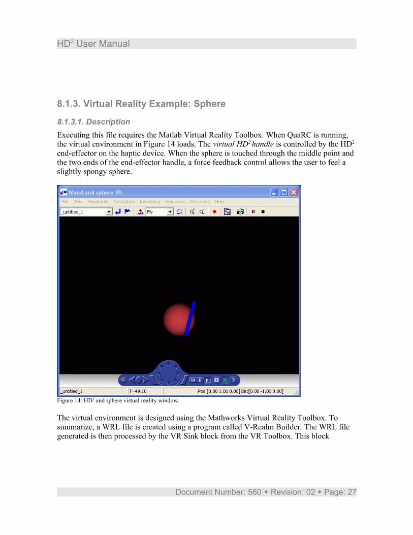
8.1.3. Virtual Reality Example: Sphere
8.1.3.1. DescriptionExecuting this file requires the Matlab Virtual Reality Toolbox. When QuaRC is running, the virtual environment in Figure 14 loads. The virtual HD2 handle is controlled by the HD2
end-effector on the haptic device. When the sphere is touched through the middle point and the two ends of the end-effector handle, a force feedback control allows the user to feel a slightly spongy sphere.
Figure 14: HD2 and sphere virtual reality window.
The virtual environment is designed using the Mathworks Virtual Reality Toolbox. To summarize, a WRL file is created using a program called V-Realm Builder. The WRL file generated is then processed by the VR Sink block from the VR Toolbox. This block
Document Number: 560 Revision: 02 Page: 27

HD2 User Manual
displays the virtual environment when the Simulink diagram is ran, i.e. that is when it is run in External mode with QuaRC.
8.1.3.2. Operating ProcedureBefore running the following example, please ensure the following has been performed:
● The device has been properly calibrated, as described in Sections 7. ● Disable the E-Stop by pulling on the red E-Stop push button. The E-Stop (compo-
nent #27) light should go off on the device back panel.● It is recommended that the calibration jig be removed, using the two thumbscrews
(Component #10).
Follow these steps to run the VR Example:Step 8. Load Matlab and set the Current Directory to the location of the lab files
provided on the HD2 CD (these files should be copied to your hard disk).
Step 9. Open the HD2_Sphere.mdl Simulink diagram.
Step 10. If you have several Q8 boards installed, double click on the HIL Initialize block and enter in the Board identifier input box the board number of the Q8 connected to the corresponding HD2_Sphere.mdl. Ignore this step and keep the board to 0 if you only have a single Q8 board installed in your PC.
Step 11. In the Simulink diagram, click on QuaRC | Build to generate the QuaRC executable.
Step 12. Move the device end-effector to the center position where it is approximately in the middle of the workspace. The sphere is defined such that it always starts a few centimeters away on the right hand side of the end-effector at the time the simulation starts running.
Step 13. Click on the Run button in the Simulink model tool bar to begin running the controller. The VR Sink window shown in Figure 14 should load.
Step 14. Move the device end-effector around and observe how the virtual HD2 handle in the VR Sink window moves accordingly.
Step 15. Now move the HD2 end-effector to touch the sphere. You should feel some resistance when the handle comes into contact with the red sphere at the middle and the two ends of the handle.
Document Number: 560 Revision: 02 Page: 28
HD2 User Manual
Step 16. To stop the session, hold on to the device handle and click on the Stop button in the Simulink model tool bar.
8.1.4. HD2_Cube.mdlThis model can be used as a demo to familiarize the user with basic operation principles of the HD2 system. The user is encouraged to read the description given above about the HD2_Position_Control.mdl file, before running this demo since the HD2_Cube.mdl file has the same underlying structure as this file.
The demo defines an imaginary cube with user chosen dimensions around the starting position of the end-effector. When the model is run, the end-effector can be moved around freely as long as it stays within the cube dimensions. However once you try to bypass any of the cube sides, opposing forces will be exerted on the end-effector not allowing you to move it outside the cube dimensions.
The HIL Interfacing and the HD2 Interface blocks, perform the same functionality as described in the HD2_Position_Control.mdl section. The “x_mean” and “theta” signals, which are outputs of the HD2 Interface block contain world co-ordinate position and orientation of the HD2's end-effector. The first sample of this signal denotes the initial position of the end-effector when the model is running. This sample is latched and assigned to “x_cmd”.
In the World-Based PV Controller block you can specify the Dead Zone block parameters where you can set your cube dimensions by specifying the dead zone upper and lower ranges. By subtracting x_cmd from “x” the controller knows if the user is operating in the “dead zone” or not. If this difference falls in the dead zone range, meaning that the user is still inside the cube dimensions, the value zero is fed into the controller and hence Force will be zero. As soon as the user tries to bypass one of the cube sides, the difference between “x_mean” and HD2_Cmd falls outside the dead zone range and Force will not be zero anymore. In this case you will feel an opposing force on the HD2 not allowing you to move the end-effector outside the cube dimensions.
It is the Force signal that is fed into the HD2 Interface block where the torque to be applied to the motors is calculated using the HD2 Jacobian. This torque is converted to a current and assigned to the HD2_Current signal before being written to the Q8.
Document Number: 560 Revision: 02 Page: 29
HD2 User Manual
9. References
[1] Q4/Q8 User Manual.
[2] QuaRC HTML Help Files.
[3] QuaRC Installation Manual.
[4] HD2 Dynamic Equations - Maple Worksheet.
Document Number: 560 Revision: 02 Page: 30
HD2 User Manual
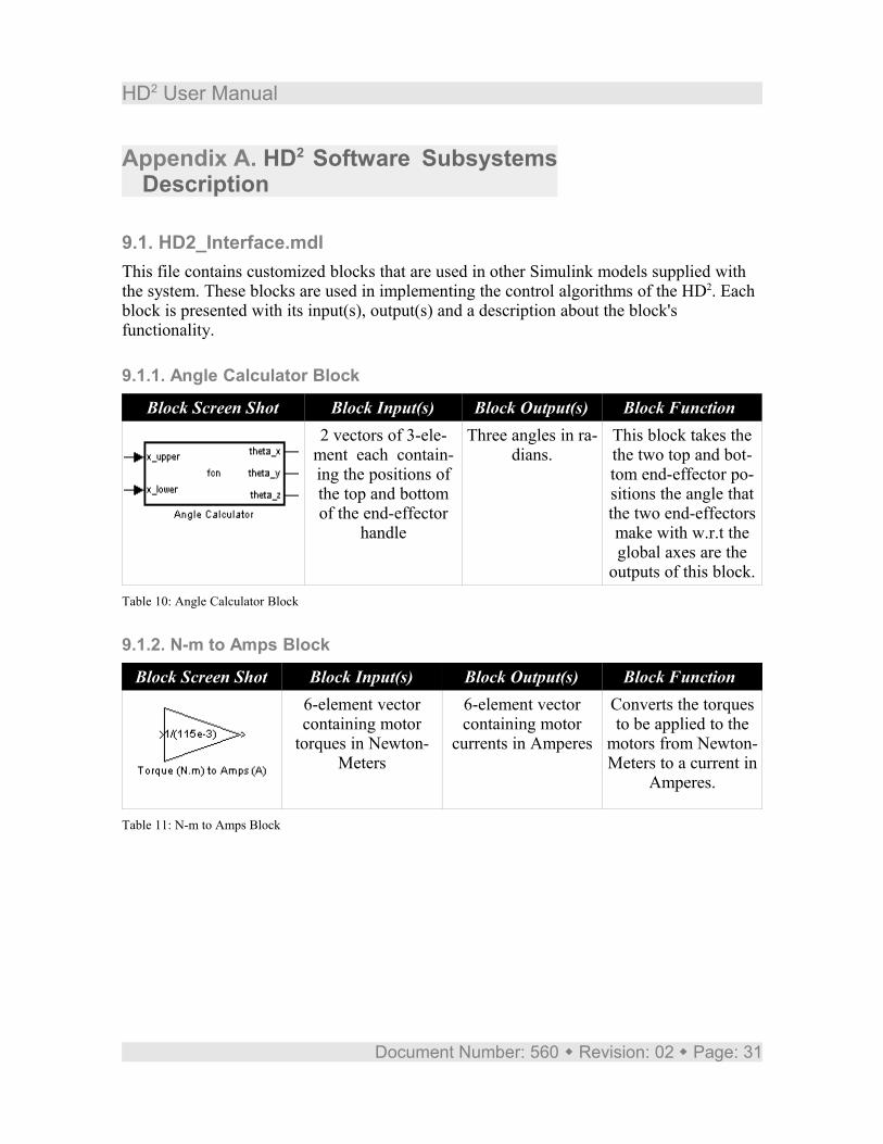
Appendix A. HD2 Software Subsystems Description
9.1. HD2_Interface.mdlThis file contains customized blocks that are used in other Simulink models supplied with the system. These blocks are used in implementing the control algorithms of the HD2. Each block is presented with its input(s), output(s) and a description about the block's functionality.
9.1.1. Angle Calculator Block
Block Screen Shot Block Input(s) Block Output(s) Block Function 2 vectors of 3-ele-
ment each contain-ing the positions of the top and bottom of the end-effector
handle
Three angles in ra-dians.
This block takes the the two top and bot-tom end-effector po-sitions the angle that the two end-effectors make with w.r.t the global axes are the
outputs of this block.Table 10: Angle Calculator Block
9.1.2. N-m to Amps Block
Block Screen Shot Block Input(s) Block Output(s) Block Function 6-element vector containing motor
torques in Newton-Meters
6-element vector containing motor
currents in Amperes
Converts the torques to be applied to the
motors from Newton-Meters to a current in
Amperes.
Table 11: N-m to Amps Block
Document Number: 560 Revision: 02 Page: 31
HD2 User Manual
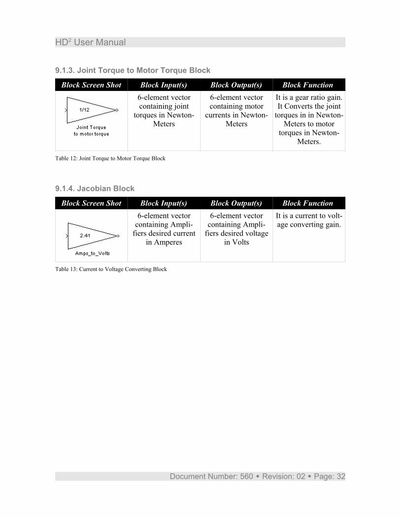
9.1.3. Joint Torque to Motor Torque Block
Block Screen Shot Block Input(s) Block Output(s) Block Function 6-element vector containing joint
torques in Newton-Meters
6-element vector containing motor
currents in Newton-Meters
It is a gear ratio gain. It Converts the joint
torques in in Newton-Meters to motor
torques in Newton-Meters.
Table 12: Joint Torque to Motor Torque Block
9.1.4. Jacobian Block
Block Screen Shot Block Input(s) Block Output(s) Block Function 6-element vector
containing Ampli-fiers desired current
in Amperes
6-element vector containing Ampli-
fiers desired voltage in Volts
It is a current to volt-age converting gain.
Table 13: Current to Voltage Converting Block
Document Number: 560 Revision: 02 Page: 32
HD2 User Manual
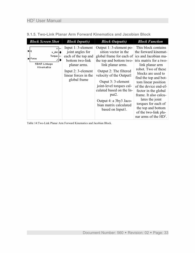
9.1.5. Two-Link Planar Arm Forward Kinematics and Jacobian Block
Block Screen Shot Block Input(s) Block Output(s) Block Function Input 1: 3-element
joint angles for each of the top and
bottom two-link planar arms.
Input 2: 3-element linear forces in the
global frame
Output 1: 3-element po-sition vector in the
global frame for each of the top and bottom two-
link planar arms.Output 2: The filtered
velocity of the Output1 Ouput 3: 3-element
joint-level torques cal-culated based on the In-
put2. Output 4: a 3by3 Jaco-bian matrix calculated
based on Input1.
This block contains the forward kinemat-ics and Jacobian ma-trix matrix for a two-
link planar arm robot. Two of these blocks are used to
find the top and bot-tom linear position
of the device end-ef-fector in the global frame. It also calcu-
lates the joint torques for each of the top and bottom of the two-link pla-nar arms of the HD2.
Table 14:Two-Link Planar Arm Forward Kinematics and Jacobian Block.
Document Number: 560 Revision: 02 Page: 33
HD2 User Manual
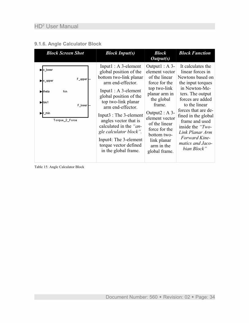
9.1.6. Angle Calculator Block
Block Screen Shot Block Input(s) Block Output(s)
Block Function
Input1 : A 3-element global position of the
bottom two-link planar arm end-effector.
Input1 : A 3-element global position of the top two-link planar arm end-effector.
Input3 : The 3-element angles vector that is
calculated in the “an-gle calculator block”.Input4: The 3-element torque vector defined in the global frame.
Output1 : A 3-element vector
of the linear force for the top two-link planar arm in
the global frame.
Output2 : A 3-element vector
of the linear force for the bottom two-link planar arm in the
global frame.
It calculates the linear forces in
Newtons based on the input torques in Newton-Me-ters. The output forces are added
to the linear forces that are de-fined in the global
frame and used inside the “Two-Link Planar Arm Forward Kine-
matics and Jaco-bian Block”
Table 15: Angle Calculator Block
Document Number: 560 Revision: 02 Page: 34