Embed Size (px)
Citation preview
Development of the Haptic Device Using Linear Oscillatory Actuators for the Disabled
Takashi Suzuki1*, Kazushige Magatani2
1 Electrical and Electronic System, Graduate School of Engineering, Tokai University, Kanagawa, Japan. 2 Departments of Electrical and Electronic Engineering, Tokai University, Kanagawa, Japan. * Corresponding author. Tel.: +81-463-58-1211; email: [email protected] Manuscript submitted May 29, 2016; accepted July 10, 2016. doi: 10.17706/ijbbb.2016.6.3.99-104
Abstract: The objective of this study is the development of the device gives direction of power vector for the
disabled. The device made up of 4 stack linear oscillatory actuators on each 3-axis (X-axis, Y-axis, Z-axis).
These actuators are mounted on the acrylic base plate. This base plate was embedded in the resin sphere
with a diameter of 50mm. We can feel the direction of power using this device. Angles intended to display
are transform to the spherical polar coordinate in our device. The microprocessor makes PWM signals
based on the spherical polar coordinates. These PWM signals drive 12 actuators. In the future, it will be
possible to guide the visually-impaired in arbitrary direction and to feedback the haptic sense of EMG
prosthetic hand.
Key words: Linear oscillatory actuators, haptic device, EMG.
1. Introduction
Development of the haptic devices has been attempted over the years for the disabled [1]-[6]. We have
considered that we need to develop a simple device which served high fidelity haptic sense for the visually
impaired. In addition, we have been developing the electromyogram prosthetic hand. In order to be possible
for physically handicapped people to accurate control the EMG prosthetic hand, the developed device is also
designed to feedback the haptic sense of EMG prosthetic hand. The purpose of this study is developing such
device and evaluating it.
In this study, we displayed haptic sense for a human’s hand using 12 linear oscillatory actuators. 3 sets of
Quad linear oscillatory actuators are fixed so that they are orthogonal to each other, thereby the developed
device displays arbitrary vector with vibration. This system is used Spherical Polar Coordinates. We make it
possible for the system to output haptic sense of arbitrary direction from input 2 angles (𝜃(deg) and
𝜙(deg)), PWM frequency (Hz) and display pattern period(s). We report the progress of the developing
system.
2. Tactile Display System
2.1. Approach of Producing a Pulling Sensation
A linear oscillatory actuator generates omnidirectional vibration from the reciprocating motion of the
weight in the actuator in normal use. However, in our system, the movement of a weight in a linear
oscillatory actuator is braked in one direction of the reciprocating motion by using PWM. As the result, the
International Journal of Bioscience, Biochemistry and Bioinformatics
99 Volume 6, Number 3, July 2016
actuator generates a force in one direction. In particular, to begin with, the magnet (a weight in an actuator)
has been driven to the one side. Next, the motion of the magnet is braked by shorting driving coil when the
magnet returns to its initial position. In other words, kinetic energy is converted into heat when the magnet
returns to its initial position. Thus a bias sensation in the reciprocating motion occurs. However, this
sensation is very small, so in order to degenerate recognizable biased sensation, we developed a periodic
driving pattern for the actuator. In other words, we design the driving pattern for the actuator which
displays the intended direction every.
2.2. Spherical Haptic Device
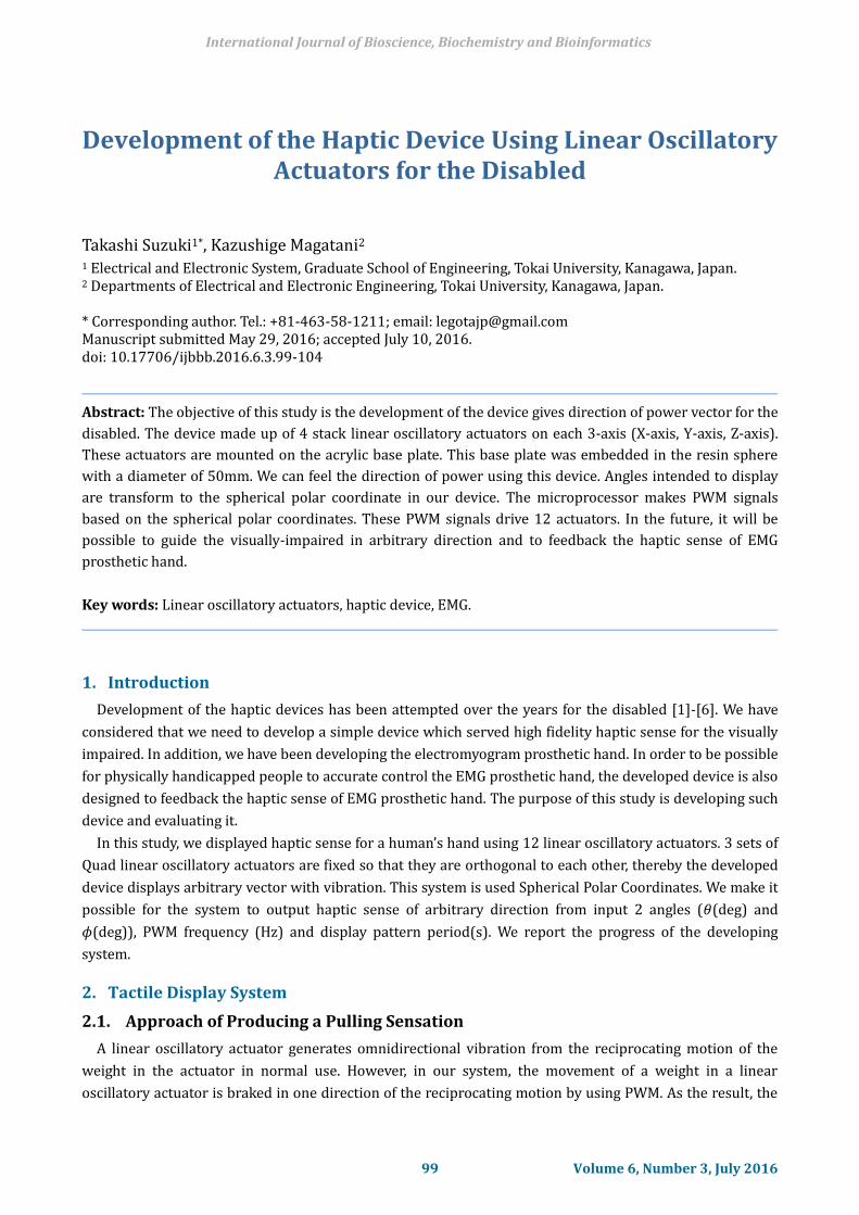
Figure 1(a) shows the skeleton model of spherical device. As shown in Figure 1(a), the device was
constructed twelve linear oscillatory actuators (LD14-002; Copal Co., Ltd.). We created the skeleton of the
device by bonding a linear vibration actuator on the circular acrylic plate. This skelton is molded by resin as
a 5cm diameter sphere. Wires from Driving coils were connected to the pin header (2pin × 12pin) that is
attached to the outside of the sphere. The pin header and the developed control board are connected via a
flat cable. Figure 1(b) shows the developed haptic device.
(a) (b)
Fig. 1. A developed haptic device.
2.3. Microprocessor Control Board
The MPU (ATmega64A) controls 12 linear oscillatory actuators. ATmega64A is a one chip microcontroller
that is kind of AVR microcontroller series. 12 full-bridge driver IC (BD6211F) drives 12 linear oscillatory
actuators. This IC has three types of driving status (forward, reverse and brake) that are able to be set by
2bit signals. The joystick (MX-1711RR manufactured by Tsubame Musen Co., Ltd.,) is connected to A/D
converter that is built in the MPU in order to enter driving parameters. 𝜙 (0°≤ 𝜙 ≤ 90°) means X-axis
angles of the joystick, and 𝜃 (0°≤ 𝜃 ≤ 90°) also means the Y-axis angle of the joystick in this paper. The
input signal from joystick is a temporary. In the future, we are going to implement software which calculates
input angles from GPS data and 3-axis gyro sensor data. As mentioned later, we didn't use joystick in
evaluation experiment.
2.4. System Control Software
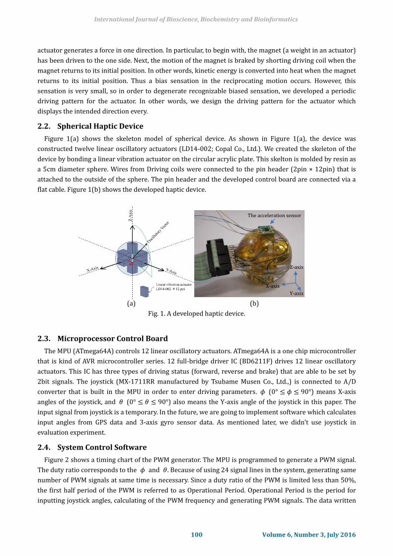
Figure 2 shows a timing chart of the PWM generator. The MPU is programmed to generate a PWM signal.
The duty ratio corresponds to the 𝜙 and 𝜃. Because of using 24 signal lines in the system, generating same
number of PWM signals at same time is necessary. Since a duty ratio of the PWM is limited less than 50%,
the first half period of the PWM is referred to as Operational Period. Operational Period is the period for
inputting joystick angles, calculating of the PWM frequency and generating PWM signals. The data written
The acceleration sensor
Z-axis
X-axis
Y-axis
International Journal of Bioscience, Biochemistry and Bioinformatics
100 Volume 6, Number 3, July 2016
to the output register is temporarily stored in the array of 16bit × 128 at first in the Operational Period. The
value of the array represented by each 16bit indicates output channel information and information of the
driving method. The order of the array indicates the time series. The later half of one cycle PWM is referred
to as Driving Period. Driving Period is divided by 128. The MPU selects one of the 16bit data for each
divided period, and the 16bit data is provided to the output register. The duty ratio of PWM is calculated
each channel, using the following formulas.
X Axis Power Ratio = sin𝜃 ∙ cos𝜙 (1)
Y Axis Power Ratio = sin𝜃 ∙ sin𝜙 (2)
Z Axis Power Ratio = sin𝜃 (3)
Fig. 2. Timing chart of the haptic device.
3. Evaluation Experiment
3.1. Experimental Method
In the experiment, the 3-axis acceleration sensor (ADXL335) is set on the top of the spherical haptic
device. Fig. 1(a) shows the position of the sensor. We wrapped up the device in clay to put a mechanically
load on the device. The measurement range of this sensor is ± 3g(m s2 ). Its sensitivity is 330mV/g.
Acceleration values of each axis (X-axis, Y-axis and Z-axis) are obtained as voltage output. This waveform of
the output voltage was observed with an oscilloscope. We also observed X-Y lissajous pattern and X-Z
lissajous pattern. We could confirm the amplitude and phase difference of the acceleration of the respective
axis. Further, we depicted the theoretical lissajous pattern from theoretical formulas ((1)-(3)).
Measurement figures were compared with theoretical figures. Table 1 shows specified directions in the
evaluation experiment.
3.2. Result of the Experiment
International Journal of Bioscience, Biochemistry and Bioinformatics
101 Volume 6, Number 3, July 2016
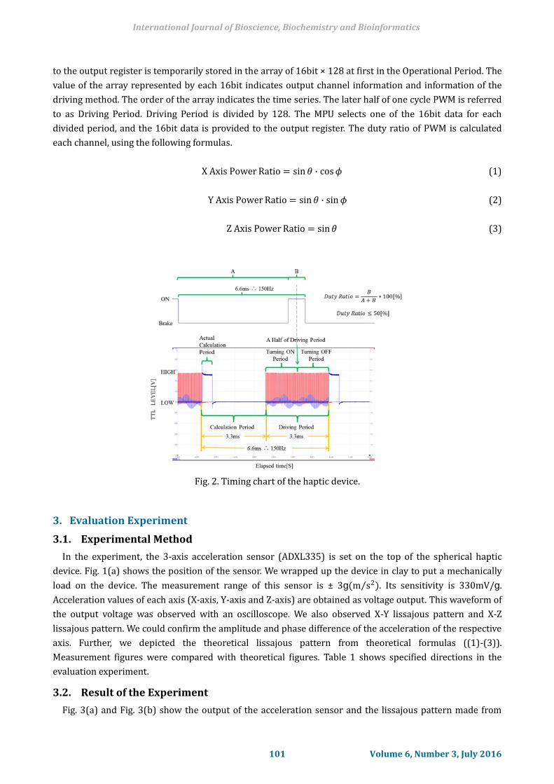
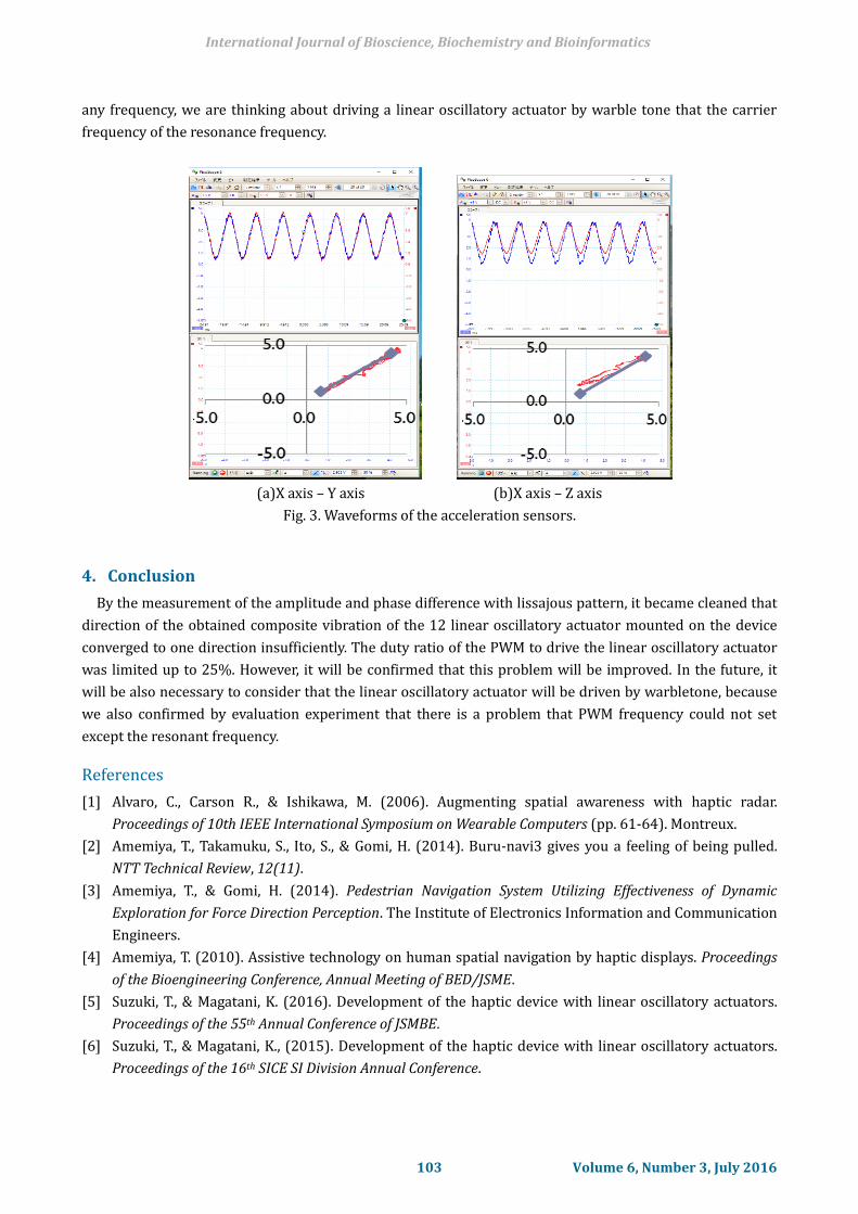
Fig. 3(a) and Fig. 3(b) show the output of the acceleration sensor and the lissajous pattern made from
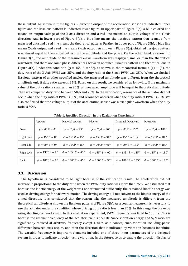
these output. As shown in these figures, 2 direction output of the acceleration sensor are indicated upper
figure and the lissajous pattern is indicated lower figure. In upper part of Figure 3(a), a blue colored line
means an output voltage of the X-axis direction and a red line means an output voltage of the Y-axis
direction. And in lower part of Figure 3(a), a blue line means the lissajous pattern that is made from
measured data and a red line means the theoretical pattern. Further, in upper part of Figure 3(b), a blue line
means X-axis output and a red line means Z-axis output. As shown in Figure 3(a), obtained lissajous pattern
was almost equal to theoretical pattern in the amplitude and the phase. On the other hand, as shown in
Figure 3(b), the amplitude of the measured Z-axis waveform was displayed smaller than the theoretical
waveform, and there are some phase differences between obtained lissajous pattern and theoretical one in
Figure 3(b). Under this condition (𝜙 = 45°, 𝜃 = 45°), as shown in the theoretical formula (1) ~ (3), the
duty ratio of the X-Axis PWM was 25%, and the duty ratio of the Z-axis PWM was 35%. When we checked
lissajous pattern of another specified angles, the measured amplitude was different from the theoretical
amplitude only if duty ratio exceeds 25%. Based on this result, we considered as following. If the maximum
value of the duty ratio is smaller than 25%, all measured amplitude will be equal to theoretical amplitude.
Then we compared duty ratio between 50% and 25%. In the verification, resonance of the actuator did not
occur when the duty ratio of PWM is 50%, and resonance occurred when the duty ratio of PWM is 25%. We
also confirmed that the voltage output of the acceleration sensor was a triangular waveform when the duty
ratio is 50%.
Table 1. Specified Direction in the Evaluation Experiment
Upward Diagonal upward Edge-on Diagonal Downward Downward
Front 𝜙 = 0°,𝜃 = 0° 𝜙 = 0°,𝜃 = 45° 𝜙 = 0°,𝜃 = 90° 𝜙 = 0°,𝜃 = 135° 𝜙 = 0°,𝜃 = 180°
Right front 𝜙 = 45°,𝜃 = 0° 𝜙 = 45°,𝜃 = 45° 𝜙 = 45°,𝜃 = 90° 𝜙 = 45°,𝜃 = 135° 𝜙 = 45°,𝜃 = 180°
Right side 𝜙 = 90°,𝜃 = 0° 𝜙 = 90°,𝜃 = 45° 𝜙 = 90°,𝜃 = 90° 𝜙 = 90°,𝜃 = 135° 𝜙 = 90°,𝜃 = 180°
Right back 𝜙 = 135°,𝜃 = 0° 𝜙 = 135°,𝜃 = 45° 𝜙 = 135°,𝜃 = 90° 𝜙 = 135°,𝜃 = 135° 𝜙 = 135°,𝜃 = 180°
Back 𝜙 = 180°,𝜃 = 0° 𝜙 = 180°,𝜃 = 45° 𝜙 = 180°,𝜃 = 90° 𝜙 = 180°,𝜃 = 135° 𝜙 = 180°,𝜃 = 180°
3.3. Discussion
The hypothesis is considered to be right because of the verification result. The acceleration did not
increase in proportional to the duty ratio when the PWM duty ratio was more than 25%. We estimated that
because the kinetic energy of the weight was not attenuated sufficiently, the remained kinetic energy was
used as driving energy for backward motion. The driving energy did not convert to the kinetic energy of the
aimed direction. It is considered that the reason why the measured amplitude is different from the
theoretical amplitude as shown the lissajous pattern of Figure 3(b). As a countermeasure, it is necessary to
use the actuator under the condition whose driving duty ratio is less than 25%. In this range the brake by
using shorting coil works well. In this evaluation experiment, PWM frequency was fixed to 150 Hz. This is
because the resonant frequency of the actuator itself is 150 Hz. Since vibration energy and S/N ratio are
significantly reduced at arbitrary frequency except 150Hz. As a consequence, vibration including phase
difference between axes occurs, and then the direction that is indicated by vibration becomes indefinite.
The variable frequency is important elements included one of three input parameters of the designed
system in order to indicate direction using vibration. In the future, so as to enable the direction display of
International Journal of Bioscience, Biochemistry and Bioinformatics
102 Volume 6, Number 3, July 2016
any frequency, we are thinking about driving a linear oscillatory actuator by warble tone that the carrier
frequency of the resonance frequency.
(a)X axis – Y axis (b)X axis – Z axis
Fig. 3. Waveforms of the acceleration sensors.
4. Conclusion
By the measurement of the amplitude and phase difference with lissajous pattern, it became cleaned that
direction of the obtained composite vibration of the 12 linear oscillatory actuator mounted on the device
converged to one direction insufficiently. The duty ratio of the PWM to drive the linear oscillatory actuator
was limited up to 25%. However, it will be confirmed that this problem will be improved. In the future, it
will be also necessary to consider that the linear oscillatory actuator will be driven by warbletone, because
we also confirmed by evaluation experiment that there is a problem that PWM frequency could not set
except the resonant frequency.
References
[1] Alvaro, C., Carson R., & Ishikawa, M. (2006). Augmenting spatial awareness with haptic radar.
Proceedings of 10th IEEE International Symposium on Wearable Computers (pp. 61-64). Montreux.
[2] Amemiya, T., Takamuku, S., Ito, S., & Gomi, H. (2014). Buru-navi3 gives you a feeling of being pulled.
NTT Technical Review, 12(11).
[3] Amemiya, T., & Gomi, H. (2014). Pedestrian Navigation System Utilizing Effectiveness of Dynamic
Exploration for Force Direction Perception. The Institute of Electronics Information and Communication
Engineers.
[4] Amemiya, T. (2010). Assistive technology on human spatial navigation by haptic displays. Proceedings
of the Bioengineering Conference, Annual Meeting of BED/JSME.
[5] Suzuki, T., & Magatani, K. (2016). Development of the haptic device with linear oscillatory actuators.
Proceedings of the 55th Annual Conference of JSMBE.
[6] Suzuki, T., & Magatani, K., (2015). Development of the haptic device with linear oscillatory actuators.
Proceedings of the 16th SICE SI Division Annual Conference.
International Journal of Bioscience, Biochemistry and Bioinformatics
103 Volume 6, Number 3, July 2016

Takashi Suzuki was born in Yokohama, Japan, in 1991. He received the B.E. degree in
electrical engineering from the Tokai University, Kanagawa, Japan, in 2015. His current
research interests include medical electronics.
Kazushige Magatani was born in Tokyo, Japan, in 1955. He received the B.E., M.E., and
Ph.D. degrees in electro communication engineering from the Waseda University, Tokyo,
Japan, in 1981, 1983, and 1987, respectively.
He joined the School of Science and Engineering Waseda University, Tokyo, Japan, as
Research Assistant in 1985. In 1990 he joined the Department of Electrical Engineering
Tokai University, Kanagawa, Japan, as a lecturer, and became an associate professor in
1994, and a professor in 2003.
His main area of research interests are biomedical engineering and rehabilitation engineering. He is a
member of the Japanese Society for Medical and Biological Engineering, and the Society of Instrument and
Control Engineers.
International Journal of Bioscience, Biochemistry and Bioinformatics
104 Volume 6, Number 3, July 2016