Embed Size (px)
Citation preview
The Automated Craftsman Preliminary Research
David Alan Bourne
CM U-RI-TR-87-22
Robotics Institute Carnegie Mellon University
Pittsburgh, PA, 15213
November 1987
Special thanks for contributions from: Jeff Baird Jim Dillinger Paul Englert Morris Goldstein Caroline Hayes Brack Hazen Dan McKeel Barry Taylor Duane T. Williams Paul Wright
Copyright 0 1987 Carnegie Mellon University
This work has been supported in part by the Air Force Wright Aeronautical Laboratories, Materials Laboratory, Air Force systems Command, Wright-Patterson, Air Force Base, Ohio, Contract No. F-33615-86-C-5038. Additional funding has been received form the Expert Machinist Consortium at CMU.

TaMe of Contents i
Table of Contents 1. Introduction 2. Qualitative Control in Manufacturing
2.1. THE METHODS 2.1 .l. programming Environments - Objectives 1 through 4 2.1.2. The CML Programming Environment 2.1.3. Ai Analysis of Traditional Process Controls - Objective 5 and 6 2.1.4. Qualitative Control Models 2.1.5. The Control
2.2. SUMMARY OF CONTRIBUTION 2.3. REFERENCES
3. Preparing A Machlne-Action Plan 3.1. ABOUT THE MACHINIST PROGRAM
3.1 .l. Evaluation of the Machinist Program against Human Apprentices. 3.1.2. Protocols on Additional Fixture Types
3.2.1. Planning with incomplete information 3.2.1 .l. isolating Areas of Uncertainty 3.2.1.2. Using Extra Conservatism 3.2.1.3. Using a Number of Alternative Soiutlons, and in-process Feedback 3.2.1.4. Using in-Process Feedback to Add Process Steps 3.2.1.5. Making Analogies to other materials. 3.2.1.6. Summary of Planning with incomplete information
3.2. STEPS TO EXTEND THE ORIGINAL PLANNER
3.2.2. Learning Program 3.3. FUTURE WORK 3.4. References
4. Investigations on the Use of Sensors in Machining 4.1. introduction 4.2. Somatic Knowledge Engineering
4.2.1. Steps In Human Machining 4.2.2. Human Sensory Monitoring 4.2.3. The Craftsman's Internal Design Dlaiogues 4.2.4. Discussion
4.4.1. Preprocess 4.4.2. in-Process 4.4.3. Postprocess
4.5. Five Case Studies 4.5.1. Measurement 4.5.2. Preform Gauging 4.5.3. Tool Wear Monitoring 4.5.4. Surface Quality Monitoring 4.5.5. Machine Tool Monitoring
4.6. issues In Accuracy and Understanding 4.7. The Design of Vision Applications
4.7.1. Design Tradeoffs
4.3. A Structured Approach Toward Vision Engineering 4.4. Human Use of Vision during Machining
4.7.1 .l. Constraints Versus Data Generality 4.7.1.2. Processing Effort Versus Data Specificity 4.7.1.3. Flexibility versus Data Specificity
3 5 8 9
10 11 13 17 18 18 21 21 22 23 23 23 23 24 24 26 26 27 27 30 31 33 33 33 33 34 37 37 38 39 39 39 40 40 40 41 41 41 47 47 52 52 52 52 53
ii Table of Contents
4.7.2. Sufficient Data and Processing Ability 4.7.3. Pian Generation
4.8. Design Paradigm Applied to an Autonomous System 4.9. References
5. Workholding: Qualitative and Quantitative Planning 5.1. Workholding: Managing Qualitathre and Quantitative Knowledge
5.1 .l. Qualitative branch of control loop 5.1.1 .l. Feature selection module 5.1.1.2. Clamp selection module 5.1.1.3. Clamp and part placement module
5.2. Summary of Contrlbutions
6.1. The Flexible Clamping System (FLECS) philosophy
6.2. Implementation methodology
6. Novel Tools for Intelligent Machining
6.1 .l. Fixturing 6.1.2. Environment
6.2.1. Novel tooling 6.2.2. Position measurement methods
6.2.2.1. Touch probe 6.2.2.2. Machine vision 6.2.2.3. Using the data
6.2.3. Clamping technique 6.2.4. Self-manipulation 6.2.5. The gripper 6.2.6. Robot lntegratlon
6.3.1. Ovewiew and design phliosophy 6,3.2. Electronics
6.3.2.1. i/O 6.3.2.2. Force measurement 6.3.2.3. Servo controls 6.3.2.4.5~~ controls interface
6.3.3. Software 6.3.3.1. Typfcai production sequence
6.3.4. Software features 6.3.5. Mechanisms
6.3.5.1. Grlpper 6.3.5.2. TIlUpan staging platform 6.3.5.3. Clamping system 6.3.5.4. Supportfng systems
7. Evaluation of a Workstation Architecture
6.3. System detafls
6.4. Conclusions and future directions
7.1. Introduction 7.2. Crlteria
7.2.1. Applications: Symbolic verses Real-Time Processing 7.2.2. Performance
7.2.2.1. Caveats 7.2.2.2. Notes on Individual machines 7.2.2.3. Task and Machines
7.2.3. Languages 7.2.4. Compatibility with Existing Facllities
53 54 54 56 57 57 61 61 64 77 87 89 89 89 90 90 90 90 91 92 93 93 93 93 93 95 95 96 96 96 96 99
1 00 100 101 102 102 103 104 105 106 109 109 1 09 109 110 112 112 113 114 115

Table of Contents
7.3. Conclusion
iii
115

iv Ust of Figures
Ust of Figures V
List of Figures Figure 1-1 : First Map of The IMW Controller Figure 2-1 : The Factory Hierarchy Figure 2-2: Some User Objectives of An Automated System Figure 2-3: System Requirements Figure 24: Three levels of representation Figure 2-5: The GFM Manufacturing Cell for Making Pre-form Turbine Blades Figure 2-6: Contributions of CML Figure 2-7: A Traditional Feedback Control System Figure 28: The Assumption of Time Varying Continuity Figure 2-9: Qualitative Control Spaces Figure 2-1 0: Nested Control Elements Figure 2-1 1 : Goals of Qualitative Control Flgure 3-1 : Average Plan Rating for Each Subject Figure 3-2: A three-dimentional veiw of the part Figure 3-3: Three alternative ways of clamping the part to cut ears. Figure 34: The steps of a sample pian Flgure 3-5: Method of Protocol Analysis Figure 3-6: A Mock of random height, width and depth, drawn by the Knowledge
Engineer Program. Figure 3-7: A graph of the width of the the part against maximum allowable height Figure 4-1 : Nine stages in the machining of a "onesf-a-kind" metal part Figure 4-2: The use of visual monitoring during machining Figure 4-3: Example internal dialogue Figure 44: The use of visual and auditory monitoring during machining Figure 4-5: Visual and auditory monitoring during roughing pass Figure 4-6: Dialogue between vision system and controller Figure 4-7: Photograph of laboratory gauge setup and schematic diagram Ftgure 4-8: Three-dimensional reconstructions Figure 4%: image of rake face of mllling insert Figure 4-1 0: Binary image of rake face In gray with worn area in black. Figure 4-1 1 : Images and 2-D F I T S of roiled, sawcut and machined surfaces Figure 4-1 2: Image of machined surface with plot of Intensities along one scan line Figure 4-1 3: in-process machlne tool monitoring experiment Flgure 4-14: Difference images from machine tool monitoring experiment Flgure 4-1 5: Tradeoff showing accuracy versus understanding Figure 4-1 6: Data-drlven model of vision application Figure 4-1 7: Tradeoff showing constraints versus data generality Figure 4-18: Tradeoff showing processing effort versus data specificity Figure 4-1 9: Tradeoff showing flexlblllty versus data speclflclty Figure 4-20: Vision plan tree for the preform gauging example Figure 5-1 : Control Structure for Part Process Planning System Figure 5-2: Part Production States with Associated Parameters Figure 5-3: Example of a Level Ii feature guide precedence over a Level 111 feature gu Figure 54: Redesign of part fn Table 5-5, Guide A for clamplng and machlnlng Figure 6-1 : Range of clampable parts vs. Difficulty of positive iocatlon Figure 6-2: Gripper mounted in spindle Figure 6-3: The Valeron touch probe Figure 64: Hydraulic FLECS swing arm clamps Figure 6-5: FLECS system clamping a hydraulic vise. Figure 6-6: Electronic interconnect schematic Figure 6-7: Top to Bottom: The RECS I enclosure and IBY controller, and the FLECS I1
enclosure, side and top view, covers removed
3 5 6 7 9
10 12 12 13 15 15 17 22 24 25 26 28 28
30 34 34 35 36 36 38 42 43 43 44 45 46 48 49 50 51 52 53 53 55 58 60
ilde 66 70 89 91 92 94 95 97 98

vi
Figure 6-8: 5vc console Figure 6-9: 5vc interface board Figure 6-1 0: Gripper assembly Flgure 6-1 1 : Design drawing of tllt/pan mechanism. Figure 6-1 2: Clamping subplate assembly Figure 6-1 3: Coupler for novel tooling
Ust of Figures
99 100 1 02 104 105 106
List of Tables vii
List of Tables Table 5-1 : Level I Feature Selection Guides, Global Feature Guides Table 5-2: Level ii Feature Selection Guides, Local Feature Guides Table 5-3: Level 111 Feature Selection Guides, Feature Machining Efficiency Guides Table 5-4: Level I Clamp Selection Guide, Clamp Envelope Selection Guide Table 5-5: Level Ii Clamp Selection Guides, Part Volume Removal Considerations Table 5-6: Level Ii Clamp Selection Guides (cont.), Part Stability Considerations Table 5-7: Level Ii Clamp Selection Guides (cont.), Clamp Bending Considerations Table 5-8: Level ii Clamp Selection Guides (cont.), Part Buckling Considerations Table 5-9: Level ii Clamp Selection Guides (cont.), Part Vibration Considerations Table 5-10: Level Ii Clamp Selection Guides (cont.), Part Deformation, Production Rate,
and Resistance Considerations Table 5-1 1 : Level 111 Clamp Selection Guides, Clamp Changeover Considerations Table 5-12: Level I Clamp Placement Guides, Part Location and Deformation
Considerations Table 5-13: Level I Clamp Placement Guides (cont.), Part-Clamp interference
Considerations Table 5-14: Level ii Clamp Placement Guides, Part Bending Considerations Table 5-15: Level ii Clamp Placement Guides (cont.), Part Buckling Considerations Table 5-16: Level ii Clamp Placement Guides (cont.), Part Deformation, Resistance to
Movement, and Production Rate Considerations Table 5-17: Level ii Clamp Placement Guides (cont.), Part Deformation, Resistance to
Movement, and Production Rate Considerations Table 5-18: Level ii Clamp Placement Guides (cont.), Part Resistance to Movement
Considerations Table 5-19: Level 111 Clamp Placement Guides, Tool Path Symmetry Considerations Table 5-20: Level 111 Clamp Placement Guides (cont.), Part Positioning Efficiency
Considerations Table 7-1 : Workstation Timings
62 63 65 67 69 71 72 73 74 75
76 78
79
80 81 82
83
84
85 86
111


1
Abstract
The Automated Craftsman is a combination of efforts that have resulted from our past work with Westinghouse, our new work with the Expert Machinist Consortium and current support from the Air Force. The Air Force project is called the Intelligent Machining Workstation (IMW) and as such is the major research catalyst for our group. The IMW project’s major goal is to replace the skills of the metal working craftsman in order to make the first part right. The chapters in this report outline the preliminary research of the IMW group to achieve this end, while integrating the results into the general objectives of the laboratory: The Automated Craftsman.
The results reported here indicate a strong need to use hybrid qualitative and quantitative methods for process planning, process control, process monitoring (Le., sensors) and workholding (Le., fixtures and grippers). To accomplish this, we have knowledge engineered the methods of the human craftsman and as appropriate encoded their methods. Finally, we review available workstations in consideration of the IMWs implementation.


*
Introduction 3
1 Introduction The first phase of the Intelligent Machining Workstation (IMW) project has been a systematic
demonstration of the need for an IMW leading to its initial design. Despite this focus on justifying IMW, we have investigated underlying technologies that will be part of any truly intelligent workstation.
These underlying technologies form the basis of the first map for the IMW (see figure 1-1). This map is a logical breakdown of areas for research and not an actual map of software modules.
b
Advanced Planner -:+ Plan Controller
Workstation
flgure 1-1 : First Map of The IMW Controller
The general conception is for the advanced planner to take a part description and to automatically build the initial process plan for machining the part. The pbn controllerwill take individual steps of the plan and broadcast them to several intelligent subcontrollers. These subcontrollers (e.g., for the machine tool or for the sensors) will carry out the actions as appropriate. In this case, the machine tool will cut and the sensors will detect cutting. As this step in the plan comes to a close, the results will be propogated back to the plan controller. At this point, the plan controller either issues the next action or, in an error situation, plans a corrective action.
Each component of the system, whether software (e.g., the planner), mechanical hardware (e.g., the fixtures) or an electronic sensor (e.g., vision) is expected to understand the basic principles of its own operation. When an error does occur, this commonsense understanding can be used as a basis for diagnosing and correcting the error. Therefore, most of the chapters in this report have some discussion of qualitative and quantitative principles for modelling, monitoring, diagnosing, planning and controlling IMW subsystems.

4 Introduction
Qualitatlve Control In Manufacturlng 5
2. Qualitative Control in Manufacturing There is great promise for automating manufacturing systems. The quality of manufactured products
can be greatly increased by using manufacturing systems with repeatable performance, inventory can be greatly decreased by sophisticated automation planning, customer needs can be addressed by reducing batch sizes and product costs can be reduced by decreasing the turn-around time between design and manufacturing (Ayres and Miller 1983). Unfortunately, these goals have not been achieved because of the unexpectedly high costs of building integrated systems with the appropriate level of intelligence.
Manufacturing systems have been broken down into four basic levels (Wright and Bourne 1988). .A workstation - one principal machine and machine controller that in practice replaces a
single person’s station.
A cell - a set of machines and controllers that need to work cooperatively to achieve the desired effect. In practice, the cell would replace several people.
.A system - a set of workstations and/or cells where each can operate and be scheduled independently from the others.
0 A factory - a set of systems that includes all aspects of the factory (Le., order entry, inventory and manufacturing).
Office Systems
Computers
I Communications Network I
Additional Systems
Manufacturing Cells and I Manufacturing Systems
Controller
Machine Tool
flgure 2-1 : The Factory Hierarchy
This hierarchy of factory modules has been developed to take advantage of a number of practical constraints. Workcells are often put together because there is either a time critical function, a part must be loaded onto a machine before it cools off, or two machines have to work together; for instance, a robot may be needed to load a machine tool. Flexible manufacturing systems are built to take advantage of similarities between part styles and machining technologies (e& fixtures, tools and system operations). This makes it possible for a single machine to work on different part styles, which happen to have similar manufacturing requirements.
This conceptual structure along with advances in computer technology have made advances in automation possible, although there remain objectives to be achieved at every level. A partial list of these needs is outlined in figure 2-2. To meet these stated objectives, the resulting system must satisfy a number of corresponding requirements (see figure 2-3).
Each user objective imposes a design constraint on the resulting system, and in several cases the
6 Qualitative Control In Manufacturing
1. Minimal Programming Time Requlred - The cost of programming manufacturing systems has proven to be beyond the resources available to most manufacturing groups. This must be reduced by one or two orders of magnitude before these systems can become cost effective (Bourne 1986a).
2. Minimal Programming Skill Required - The programming skill currently required for building new manufacturing systems is well beyond the skill level of manufacturing employees. Most of the programming should be limited to graphics oriented layouts and actions, thus reducing the requisite skills.
3. Easy Integration - The factory is made up of many different kinds of modules all of which have different capabilities and different modes of interaction. These modules must be integratable into a unified, information rich environment (Bourne 1984). To accomplish this, each module must be able to carry out a dialogue in which information is readily requested and given out to modules that have a need to know (Bourne 1986b). When this approach is taken to the limit, the physical structure of the factory resembles the structure of an object oriented program (Taylor 1987).
4. Easy Knowledge Acqulsltion - Each module must be able to determine what information it needs and how it can be obtained in order to carry out the intended task. This may involve accessing factory wide databases, soliciting help from human experts or using the module's own sensors to determine the state of the environment.
5. Good Process Control - Each module must be able to control the task parameters it has been assigned. In the case of a robot, these task parameters would include controlling the joint axes, and in the case of a factory scheduler these task parameters would include factory throughput. In order to successfully control these processes, the module must understand the importance of the task, the time that it is expected to take, the required accuracy of the final solution, and the method of control.
6.Good Error Management - Once a serious error occurs in most control systems, the system is unable to contain the damage caused by the error. Systems that can manage errorful situations are needed. For example, nuclear power plants have neglected this issue at great cost (Lombard0 1981).
Agum 2-2: Some User Objectives of An Automated System
objectives push beyond the state-of-the-art of software engineering and artificial intelligence. The resulting list of design constraints generates a new list of system requirements that start to determine the shape of the final system.
In order to build factory systems with a minimum of effort and skill, it is necessary to automate many of the programming tasks. Most of the programming time in factory systems is expended on interfacing machines to machines and machines to people. To alleviate this expenditure, a number of computational tools must be provided to system builders to aid in machine-to-machine translation tasks. These areas (and others) will be addressed by the Programming tools that are provided in the Cell Management Language (CML).
Another time sink in programming large scale systems involves the reproduction of redundant program segments from one application to the next. For example, factory scheduling, design for automation and real time control all involve a model of the factory. This model is often recreated over and over again, a process that is not only time consuming but allows for inconsistencies to creep in between the models. It would dramatically reduce both programming and maintenance times if a single model was centralized and made available to all of these different applications. This centralized model could also include generic procedures for basic manufacturing problems. Task dependent data could then be added to the
Qualitative Control In Manufacturing 7
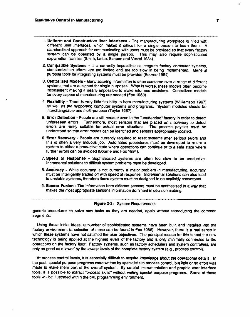
1. Unlform and Constructive User lntetfaces - The manufacturing workplace is filled with different user interfaces, which makes it difficult for a single person to learn them. A standardized approach for communicating with users must be provided so that every factory system can be operated by a single person. This may also require sophisticated explanation facilities (Smith, Lafue, Schoen and Vestal 1984).
2. Compatible Systems - It is currently impossible to integrate factory computer systems, standardization efforts are too limited and are too slow in being implemented. General purpose tools for integrating systems must be provided (Boume 1984).
3. Centralized Models - Manufacturing information is often scattered over a range of different systems that are designed for single purposes. What is worse, these models often become inconsistent making it nearly impossible to make informed decisions. Centralized models for every aspect of manufacturing are needed (Fox 1983).
4. Flexlbillty - There is very little flexibility in both manufacturing systems (Williamson 1967) as well as the supporting computer systems and programs. System modules should be interchangeable and multi-purpose (Taylor 1987).
5. Error Detection - People are still needed even in the "unattended" factory in order to detect unforeseen errors. Furthermore, most sensors that are placed on machinery to detect errors are rarely suitable for actual error situations. The process physics must be understood so that error modes can be identified and sensors appropriately located.
6. Error Recovery - People are currently required to reset systems after serious errors and this is often a very arduous job. Automated procedures must be developed to return a system to either a productive state where operations can continue or to a safe state where further errors can be avoided (Boume and Fox 1984).
7.Speed of Response - Sophisticated systems are often too slow to be productive. Incremental solutions to difficult system problems must be developed.
8. Accuracy - While accuracy is not currently a major problem in manufacturing, accuracy must be intelligently traded off with speed of response. Incremental solutions can also lead to unstable systems, therefore these system must be designed to be explicitly convergent.
9. Sensor Fusion - The information from different sensors must be synthesized in a way that makes the most appropriate sensor's information dominant in decision making.
Flgum 2-3: System Requirements
generic procedures to solve new tasks as they are needed, again without reproducing the common segments.
Using these initial ideas, a number of sophisticated systems have been built and installed into the factory environment (a selection of these can be found in Fox 1986). However, there is a real sense in which these systems have not satisfied the user objectives. The principal reason for this is that the new technology is being applied at the highest levels of the factory and is only minimally connected to the operations on the factory floor. Factory systems, such as factory schedulers and system controllers, are only as good as allowed by the lowest levels of the complete factory system (e.g.. process control).
At process control levels, it is especially difficult to acquire knowledge about the operational details. In the past, special purpose programs were written by specialists in process control, but little or no effort was made to make them part of the overall system. By careful instrumentation and graphic user interface tools, it is possible to extract "process skills" without writing special purpose programs. Some of these tools will be illustrated within the CML programming environment.
0 Qualitative Control in Manufacturing
Once process control information is modelled it is possible to build controllers that maintain acceptable levels for all of the control parameters. For example, tools heat up during cutting and this negatively affects the tool life. As long as the tool temperature is kept within "reasonable bounds," both the efficiency of cutting and the tool life can be maximized. While this may sound easy enough, it has proven difficult to build general methods for detecting in-process tool wear. Generally, the underlying physics of manufacturing processes are either so complex that no quantitative model exists, or the quantitative models that do exist are so specialized that they only yield solutions to one instance of the problem. Therefore, qualitative models must be employed that are then augmented with quantitative information as appropriate. The methods of qualitative physics will be extended to active control situations instead of strictly simulation environments that have been used to date (de Weer 1975,1985, Forbus 1985, Kuipers 1985).
The resulting controller must then use symbolic methods to access, manipulate and make inferences from these qualitative approximations of the control space. In addition to process parameters, the qualitative model will also be used to describe temporal limitations on system actions, as well as accuracy and other design requirements that are imposed externally. This web of qualitative structures will then provide causal explanations for every action and every sensation experienced by the system.
Finally, there is the age old question of what happens when there is a system error despite all of the efforts to build an "intelligent system." Most factory applications are so dangerous that the underlying fear of a catastrophic error is enough to prevent the installation of automated systems. In general, the error must be detected, the state after the error must be recognized, an action must be immediately taken to prevent a chain reaction and, finally, a plan must be constructed to recover from the error and to continue normal operations.
2.1. THE METHODS Artificiatlntelligence has many tools for building, planning diagnosing and explaining qualitative (Le.,
symbolic) systems (Hayes-Roth, Waterman and Lenat 1983). However, it is difficult to maintain system characteristics that are expected from traditional control theory: accuracy, speed of response and stability. On the other hand, traditional control theory offers methods for building fast and reliable systems (Harrison and Bollinger 1968, Whitney 1987), while it is difficutt to gain access to their structure for qualitative reasoning tasks. For this reason, layered systems have often been constructed where AI methods are used at the top for planning and traditional numerical control theory at the bottom. For example, applications have been built using this layered approach in cell control for manufacturing (Bourne and Fox 1984) and navigation tasks for mobile robots (Brooks 1986).
This work attempts to unify these two diverse approaches by extending the relatively new field of qualitative process physics (Bobrow 1985, Hobbs and Moore 1985) to permit the definition of control algorithms, while still yielding to symbolic manipulation and reasoning.
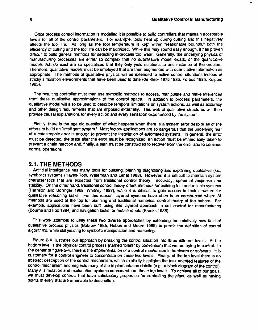
Figure 2-4 illustrates our approach by breaking the control situation into three different levels. At the bottom level is the physical control process (named "plant" by convention) that we are trying to control. In the center of figure 2-4, there is the implementation of a control mechanism in hardware or software. It is customary for a control engineer to concentrate on these two levels. Finally, at the top level there is an abstract description of the control mechanism, which explicitly highlights the task oriented features of the control mechanism and neglects many of the implementation details (e.g., a block diagram of the control). Many AI simulation and explanation systems concentrate on these top levels. To achieve all of our goals, we must develop controls that have satisfactory properties for controlling the plant, as well as having points of entry that are amenable to description.
Qualltatlve Control In Manufacturlng
Domain - of Implementation 09 9
Control 0 Description
Figure 2-4: Three levels of representation
1 2.1.1. Programming Environments - Objectives 1 through 4
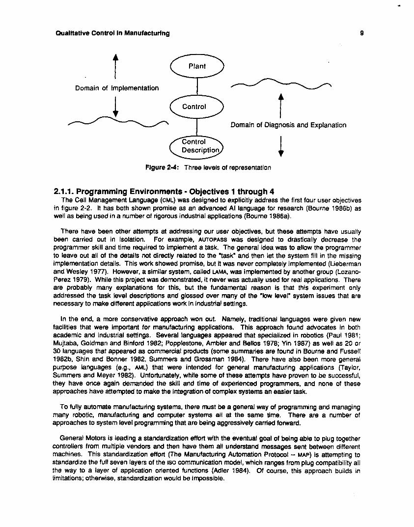
The Cell Management Language (CML) was designed to explicitly address the first four user objectives in figure 2-2. It has both shown promise as an advanced AI language for research (Bourne 1986b) as well as being used in a number of rigorous industrial applications (Bourne 1986a).
There have been other attempts at addressing our user objectives, but these attempts have usually been carried out in isolation. For example, AUTOPASS was designed to drastically decrease the programmer skill and time required to implement a task. The general idea was to allow the programmer to leave out all of the details not directly related to the "task" and then let the system f i l l in the missing implementation details. This work showed promise, but it was never completely implemented (Lieberman and Wesley 1977). However, a similar system, called LAMA, was implemented by another group (Lozano- Perez 1979). While this project was demonstrated, it never was actually used for real applications. There are probably many explanations for this, but the fundamental reason is that this experiment only addressed the task level descriptions and glossed over many of the "low level" system issues that are necessary to make different applications work in industrial settings.
In the end, a more conservative approach won out. Namely, traditional languages were given new facilities that were important for manufacturing applications. This approach found advocates in both academic and industrial settings. Several languages appeared that specialized in robotics (Paul 1981; Mujtaba, Goldman and Binford 1982; Popplestone, Ambler and Bellos 1978; Yin 1987) as well as 20 or 30 languages that appeared as commercial products (some summaries are found in Bourne and Fussell 1982b, Shin and Bonner 1982, Summers and Grossman 1984). There have also been more general purpose languages (e.g., AML) that were intended for general manufacturing applications (Taylor, Summers and Meyer 1982). Unfortunately, while some of these attempts have proven to be successful, they have once again demanded the skill and time of experienced programmers, and none of these approaches have attempted to make the integration of complex systems an easier task.
To fully automate manufacturing systems, there must be a general way of programming and managing many robotic, manufacturing and computer systems all at the same time. There are a number of approaches to system level programming that are being aggressively carried forward.
General Motors is leading a standardization effort with the eventual goal of being able to plug together controllers from multiple vendors and then have them all understand messages sent between different machines. This standardization effort (The Manufacturing Automation Protocol - MAP) is attempting to standardize the full seven layers of the is0 communication model, which ranges from plug compatibility all the way to a layer of application oriented functions (Adler 1984). Of course, this approach builds in limitations; otherwise, standardization would be impossible.
10 Qualitative Control in Manufacturing
The National Bureau of Standards also has been involved in extensive efforts to integrate and automate large scale manufacturing systems (Simpson, Hocken and Albus 1984). In brief, their approach is to build a hierarchy of controllers that manage different levels of the system. Each controller is driven by a finite state machine, which steps through actions conditioned on system states. Each action is associated with a hard-coded function, which is designed to carry the machine into the next state. While this research has shown some promise, it suffers, because every controller box in the system has to be retrofitted with a special purpose NBS function box. Therefore, this approach is more restrictive than the MAP effort. In MAP, Only the messages between controllers must be standardized, where the NBS style of integration demands that each controller be standardized.
CML is a means of integrating systems that neither calls for mass standardization efforts nor the Instead, CML is massive retooling that would be necessary to build systems in the NBS paradigm.
specifically designed to directly solve the first four user objectives in existing factories.
2.1.2. The CML Programming Environment
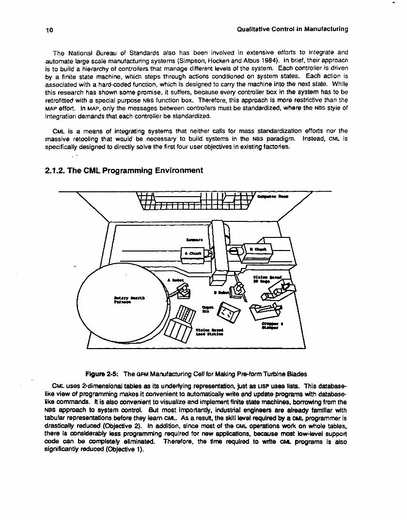
Figure 2-5: The GFM Manufacturing Cell for Making Preform Turbine Blades
CML uses 2-dimensional tables as its underlying representation, just as LISP uses lists. This database- like view of programming makes it convenient to automatically write and update programs with database- like commands. It is also convenient to visualize and implement finite state machines, borrowing from the NBS approach to system control. But most importantly, industrial engineers are already familiar with tabular representations before they learn CML. As a result, the skill level required by a CML programmer is drastically reduced (Objective 2). In addition, since most of the CML operations wok on whole tables, there is considerably less programming required for new applications, because most low-level support code can be completely eliminated. Therefore, the time required to mite CML programs is also significantly reduced (Objecb've 1).
Qualltatlve Control In Manufacturlng 11
CML was explicitly designed to solve the integration problem (Objective 3) for arbitrarily constructed systems with components supplied by multiple vendors. To accomplish this, CML provides general tools for building systems of language interpreters within an integrated environment. For example, an interrupt driven mail system receives messages from multiple communication lines, each connected to a different device, and manages a first-come-first-sere queue within a priority ordering. As each mail-piece is read, the source of the mail determines how the message should be parsed and interpreted. A table driven parser splits the mail into its logical tokens, which are then formatted as a table. These tokens are used as data for either if-then rules or as parameters to functions. As a result, the internal state of CML is updated and new messages, composed of commands and programs, are sent to underlying system components (e.g., robots and vision systems). Figure 2-6 enumerates the contributions of CML to programming languages in general.
At this level, CML is still a programming environment: a series of CML commands must be typed and interpreted, which results in a changed global environment. This text-orientation is still a difficult for non-programmers to master. However, there are many programming activities that can be done more easily within a Yeaching-by-doing" graphics environment instead of a text-oriented programming environment. In particular, graphics tools have been constructed to determine the logical sequencing of machine actions in complex systems. This particular teaching-by-doing environment is designed explicitly to teach conditional logic, where in most teaching-by-doing systems conditional logic is where text- oriented programming must begin. This has removed some of the most difficult aspects of the remaining programming task (Objective 2 and 4).
Despite CML'S success at making improvements, it still falls short of achieving good real-time process control (Objective 5 and 6). The reason for this is that CML does not have access, control or representations for the process level operations. The next section addresses the issues and methods for overcoming these shortcomings. Eventually, the goal is to build a real-time IMW controller that can effectively manage these problems as well.
2.1.3. AI Analysis of Traditional Process Controls - Objective 5 and 6
computational counterparts), or continuous feedback loops, which are based on control theory. In the past, process control has either used very simple discrete logic composed of relays (or their
The discrete logic components mostly operate on a logical level with various states becoming true and false, while the passage of time is almost completely factored out. It should be noted that some logical conditions are subtly time dependent (e.g., the temperature of a steel billet is now appropriate for forging). For the most part, it is straightforward to replace these discrete control systems with the equivalent of if-then rules. In turn, these rules are amenable to Al-oriented explanation and diagnosis. Because time has been mostly factored out of the control logic, the supervisory functions do not have to manage the details of temporal synchronization between system components. It was based on this premise that the GFM cell controller was built at a Westinghouse plant (Bourne 1984) ;see figure 2-5.
The problem with a discrete logic system is that it is allowed to run "open loop" in between logical states. For example, a cell controller can trigger a robot action but then has to wait for it to complete. This is a wonderful simplification if everything goes according to plan, but in an imperfect world this is rarely a successful strategy; in this case, the robot may never complete the action. This simplification may in fact be acceptable in a hierarchical system (see figure 2-1), so long as each level of the hierarchy manages its own "continuous problems." Unfortunately, this has not been the case, and the problems only get successively worse as they are propagated up the factory hierarchy.
At the other extreme, continuous feedback systems are strictly timedependent, and any timely intervention can throw the system off by violating basic continuity assumptions. Continuous control systems have no way to recognize, represent or change when and if they fall behind in a control activity.
12 Qualitative Control in Manufacturing
~~~
1 . CML is a complete programming environment represented in database form. This has proven to be indispensable in automatic programming tasks that are necessary to run machines in an unpredictable factory environment without human attention. Three automatic programming systems have been built in CML and applied in the factory environment:
A program that automatically constructs a cell control program from high-level
0 A program that automatically constructs gauging NC programs from a description of
.A program that writes a letter to a human programmer critiquing the quality of a
2. CML provides explicit tools for quickly building interpreters that are used to translate messages in heterogeneous machine networks. This has been demonstrated in three large applications (one built by myself and two by Westinghouse). In this regard, CML provides a database driven, context free parser that can cope with higher order languages by multiple passes over the input string. This particular parser is unique, because it combines lexical and syntactic processing into one step. Furthermore, the grammar and the parse-output are also represented in database form, which makes the output immediately convenient for processing.
3. If-then rules are represented as a function call with a list of typed arguments. When a data-table is applied to rulstable the functions "fire" only if there is data of the correct type and sometimes value in the data-table. The parameter list of the fired function is a database table of types and values. This SyStti?f?7atiC and uniform representation throughout interpretative processing is the single most significant contribution of CM. This has resulted in a significant decrease in the programming effort required for large scale manufacturing sysiems.
4. A series of CML interpreters can be pieced together into an a system of interpreters that are interconnected by a general purpose message passing scheme. This system of interpreters is driven by a database description of the current message agenda, machirmto-language assignments, message priorities, low level protocols and other system oriented information. This provides the right level of abstraction for factory engineers.
5. A system of interpreters was written in CML and applied to several large-scale manufacturing applications.
graphical input describing the cell configuration.
the part.
specified CML program.
Flgure 2-6: Contributions of CML
Reference Signal Control Signal
Input Element b Control Element I
~
flgure 2-7: A Traditional Feedback Control System
This inadequacy becomes even more pronounced when the control system operates outside of its
Qualitative Control In Manufacturing 13
intended range of application. Typically, a control system is designed and optimized for a single task, so this limitation is only uncovered when the system is "misapplied."
A traditional control loop (see figure 2-7) is made of four basic elements, though each can be made more complex. The first element defines a model that generates the initial reference signal, which in turn drives the control element. The control element transforms the reference signal into the control signal, which in turn adjusts the physical plant. The feedback element detects discrepancies between the desired solution and the actual situation in the plant and generates a feedback signal, which when added to the initial signal brings the system closer to its goal (see Harrison and Bollinger 1968 for a good introductory text).
This method of coming to a solution is equivalent to hill climbing on a single variable in a solution space with a single maximum. Indeed, this is a simple system. However, a control system must also have special characteristics that will result in finding the peak accurately, quickly and without becoming unstable (Le., diverge from the solution or endlessly oscillate around the solution). In addition, most controllers have to cope with a time varying task, such as a welding robot tracking a seam or a grinder optimizing the force of a part against the grinding wheel. Both examples have simple solutions at an instant, but the solution is shifting over time. Therefore, the controller must keep up with the ever changing task, while maintaining control. This system can be thought of as a two variable hill climbing task, but usually a strong assumption is made concerning the continuity between time frames (see figure 2-8).
If f,, ... f, are all continuous modal functions over a closed interval [a,b] then g is also continuous over the interval [m,n] when g(i)=max(fi).
a b
Flgure 2 8 : The Assumption of Time Varying Continuity
This assumption, in essence, defines a continuous ridge of solutions over time, and the controllers job is to find the initial solution and then to track it.
2.1.4. Qualitative Control Models A qualitative model of a control system consists of three components. First, there is a control space
where the "shape" of the critical control domains are represented. Second, there is a structural model of the mechanism being controlled. And finally, third, there is a control algorithm that manipulates the key control variables, and which refers to the structural model in error situations. The rest of this section focuses on qualitatively different control domains and their corresponding control algorithms. The structural models are not discussed here, but they will represent the mechanisms similarly to the semantic-network-like structures of Forbus (1 985).
Every practical device has built in limitations that defines a threshold of operation. For example, a robot arm can only lift a limited amount of weight and can only move at a limited velocity, while a vision
14 Qualitative Control in Manufacturing
system can only see with a fixed number of picture elements. Beyond these basic limits, there are often higher order limitations as well as other complex relationships between a number of variables. Critical control parameters are extracted from these processes and make up the underlying control space. Unfortunately, our attempts to analytically model manufacturing applications are often foiled by imperfections in the "real" world. Figure 2-9 summarizes some of these important relationships between control parameters by a series of simple x-y plots. This series of x-y plots is used to organize the rest of this section.
Part-a: Despite these basic difficulties, it is possible to capture the qualitative shapes of these control parameters. Part-a of figure 2-9 shows a control parameter that is monotonically increasing, and it is a simple matter to design a control system with feedback that can survive in this space, assuming that its response time is appropriate for adequately tracking the control variable. Furthermore, for AI understanding, the monotonicity of the variable suggests that the system is operating under a single principle (e.g., as cutting continues normally, tool wear increases).
Part-b: Most control spaces are not as elementary as part-a, because fundamental to the process are "limits" that cast the process into a different region of operation. For example, a tool wears until it breaks, and in this process there may be several regions of metal cutting that operate according to different physical mechanisms. Part-b shows a control space with several inflection points. These inflection points suggest a shift in the operating conditions of the process, and are good clues for both control and AI understanding.
We model these more complex control "shapes" with alternating open intervals and points (following Williams 1984, Kuipers 1985 and Forbus 1985). In control and explanation, both the intervals (rising and decreasing) and the points of inflection have significance. For example, as cutting continues -- the tool wears (interval), the tool is broken (point), and finally the tool condition stabilizes (interval). To appropriately control this variable, a feedback loop is needed to control the system in the intervals as well as rules that perform "limit analysis" across the points of inflection.
Part-c: At some point, it is no longer adequate to view a single variable in isolation. Rather, some simultaneous analysis must be performed on different variables in the same space. In fact, it is just this kind of problem that has caused conundrums in traditional control frameworks, because it is extremely difficult to balance two systems that are at cross-purposes. Whitney (1987) and Craig (1986) both discuss hybrid control systems for robotics, where both force and position are the critical control variables. In some of their solutions, time-sharing force and position goals, their own discussion is uncertain about its usefulness. Other solutions, applying force and position separately along different dimensions, are quite compelling but this solution also necessitates an AI system to perform the initial assignment of "control system" to "control axis." To visualize this solution, imagine a robot washing a window, where the position is the dominant control variable in the plane of the window and force is the critical control variable normal to the window. Each task would have a different assignment from a range of control systems.
Without developing every combination of controls, part-c illustrates one combination that has special significance. In this system, the response of one variable changes virtually instantaneously, while the other variable, by comparison, does not change at all. Kuipers (1987) has studied chemical reaction times in renal functioning that have dramatically different response times and he has developed a similar way of reasoning about their relationships. However, the unanswered question about hybrid systems like these, is how should they be represented for the purposes of active control.
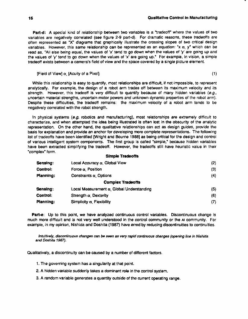
One way to view these hybrid control systems is as a hierarchy, where one control function is nested in a control element of a higher level control (see figure 2-10). With this view, each control variable can be given some orderly control over each axis, while admitting that one control variable is given the dominant role in the control task. In the force-position hybrid control, either the force variable would be vaned "instantaneously" relative to position or vice versa. This would be quite effective for cleaning a glass
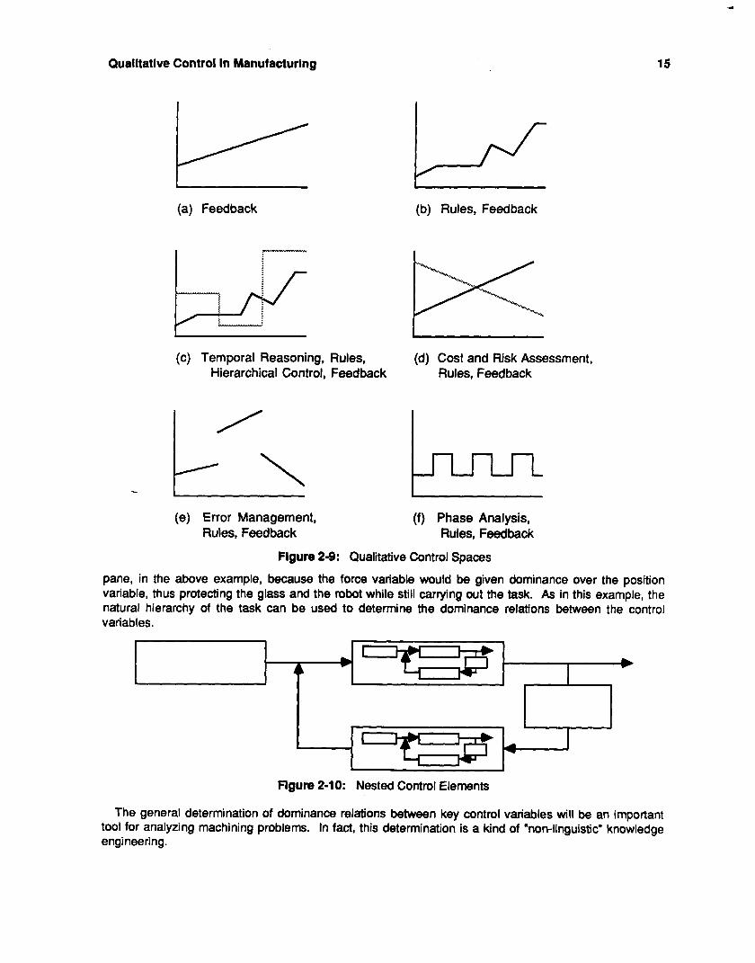
Qualitative Control in Manufacturing 15
(a) Feedback
~~~ ~ ~
(b) Rules, Feedback
(c) Temporal Reasoning, Rules, Hierarchical Control, Feedback
Cost and Risk Assessment, Rules, Feedback
(e) Error Management, Rules, Feedback
(f) Phase Analysis, Rules, Feedback
Figure 2-9: Qualitative Control Spaces
pane, in the above example, because the force variable would be given dominance over the position variable, thus protecting the glass and the robot while still carrying out the task. As in this example, the natural hierarchy of the task can be used to determine the dominance relations between the control variables.
Flgure 2-1 0: Nested Control Elements
The general determination of dominance relations between key control variables will be an important tool for analyzing machining problems. In fact, this determination is a kind of "non-linguistic" knowledge engineering.
16 Qualitative Control In Manufacturing
Part-d: A special kind of relationship between two variables is a "tradeoff" where the values of two variables are negatively correlated (see figure 2-9 part-d). For dramatic reasons, these tradeoffs are often represented as "X" diagrams that graphically illustrate the crossing slopes of two critical design variables. However, this same relationship can be represented as an equation: "x a- y" which can be read as, "All else being equal, the values of 'x' tend to go down when the values of 'y' are going up and the values of 'y' tend to go down when the values of 'x' are going up." For example, in vision, a simple tradeoff exists between a camera's field of view and the space covered by a single picture element.
[Field of View] a- [Acuity of a Pixel]
While this relationship is easy to quantify, most relationships are difficult, if not impossible, to represent analytically. For example, the design of a robot arm trades off between its maximum velocity and its strength. However, this tradeoff is very difficult to quantify because of many hidden variables (e.g., uncertain material strengths, uncertain motor powers and unknown dynamic properties of the robot arm). Despite these difficulties, the tradeoff remains: the maximum velocity of a robot arm tends to be negatively correlated with the robot strength.
In physical systems (e.g, robotics and manufacturing), most relationships are extremely difficult to characterize, and when attempted the idea being illustrated is often lost in the obscurity of the analytic representation. On the other hand, the qualitative relationships can act as design guides, provide the basis for explanation and provide an anchor for developing more complete representations. The following list of tradeoffs have been identified [Wright and Bourne 19881 as being critical for the design and control of various intelligent system components. The first group is called "simple," because hidden variables have been extracted simplifying the tradeoff. However, the tradeoffs still have heuristic value in their "complex" form.
Simple Tradeoffs
Senstng: Control: Force a- Position Planning : Constraints a- Options
Sensing: Control: Strength a- Dexterity Plannlng: Simplicity a- Flexibility
Local Accuracy a- Global View
Complex Tradeoffs Local Measurement a_ Global Understanding
Parte: Up to this point, we have analyzed continuous control variables. Discontinuous change is much more difficult and is not very well understood in the control community or the AI community. For example, in my opinion, Nishida and Doshita (1987) have erred by reducing discontinuities to continuities.
Intuitively, discontinuous changes can be seen as very rapid continuous changes (opening line in Nishida and Doshita 1987).
Qualitatively, a discontinuity can be caused by a number of different factors.
1. The governing system has a singularity at that point.
2. A hidden variable suddenly takes a dominant role in the control system.
3. A random variable generates a quantity outside of the current operating range.
Qualitative Control In Manufacturlng 17
The last of these choices is the most common approach to reasoning about a discontinuity, especially for a human craftsman in the middle of a manufacturing operation (e.g., "suddenly, a tool breaks"). The first step is to recognize what happened and second to bring the system back under control. The recognition step is explicitly missing until a discontinuity is recognized as a discontinuity. Most error and subsequent control problems for the IMW fall into this category.
Part-f: The last example of a control space shows a control variable that explicitly moves through phases. This is very common in manufacturing applications (e.g., periodic machine actions), as well as in mathematical analysis (e.g., periodic functions). Furthermore, the phase space has been studied thoroughly in both continuous domains using the Laplace transform (Harrison and Bollinger 1968) and discrete domains using the Z-transform (Cadzow 1973). Recently, Yip (1987) has undertaken a qualitative analysis of the phase space by observing qualitative changes in the "shape" of the phase diagram. While this work is tantalizing, it has not been carried out to its logical conclusion. Such a conclusion would demonstrate that a qualitative change in the phase space corresponds to a qualitative change in the control space. This is another tool that may be helpful in managing plans in the IMW controller.
1. Develop a unified framework for qualitative tools that can be used to represent, control and explain actual machine actions; especially in hard-to-analytically-model situations. In particular, this will concentrate on smoothly integrating qualitative and quantitative information.
2. Develop an approach for identifying dominance relations between control variables using a representation of the task. Demonstrate how this can be represented in a closed-loop control hierarchy and how reasoning about this system can proceed.
3. Develop an approach for representing and reasoning about "cooperative" (non-hierarchical) control variables. Contrast this with a hierarchical representation of the same system.
4. Apply qualitative analysis methods to a largescale manufacturing application, thus demonstrating the "scalability" of the approach.
5. Develop a qualitative tool that properly deals with discontinuities in the control space. This will encompass both planning strategies to avoid them, as well as recognition strategies for picking up the next control surface.
Figure 2-11 : Goals of Qualitative Control
These control spaces (part-a through part-f) can be elaborated by further knowledge engineering and further scientific investigation, or act as a basis for automated discovery (Falkenhainer 1985, Langley, et a/ 1986, Forbus and Genter 1986).
We have a range of goals for applying qualitative control to manufacturing (see figure 2-1 1). Finally, the ultimate goal is to build a control system with knowledge broad and deep enough to handle unforeseen situations in the manufacturing environment (after Hayes 1979 and 1965).
2.1.5. The Control After a model is built, the control of the physical plant must be actually carried out. The control spaces
(in figure 2-9) enumerated a range of different control strategies, but glossed over such details as how the gain is chosen in a feedback loop. In this case, constants could be used for incremental adjustments, but that would poorly reflect the operative skills of a craftsman. A different approach is to try and match the qualitative size of the increments to suit the application. This approach has been successfully tried over the last few years and a good summary can be found in Sugeno (1985). While this approach has proven
18 Qualitative Control In Manufacturing
to be adequate, we will search for a more uniform method of representing the incremental adjustments to our qualitative controls, so that qualitative and quantitative information are of equal status.
2.2. SUMMARY OF CONTRIBUTION To date, qualitative modelling has been used exclusively for simulation systems where the goal has
been to achieve behavior that matches the behavior of the actual system. While the initial applications were for circuits (electric and hydraulic), these methods are beginning to be used to model some aspects of more complicated systems such as jet engines (Rajagopalan 1984) and copying machines (Shrager, Jordan, Moran, Kiczales and Russell 1987). This work proposes the application of these methods for modelling several difficult problems in machining, as well as taking them out of the strictly simulation environment and into control.
There are several practical and theoretical hurdles that must be overcome before it is possible to build truly unattended factory systems. This work addresses these practical concerns by providing a new and novel way of implementing factory solutions to prohibitively difficult integration problems (i.e., CML). From this experience, it has been determined that there are currently no adequate solutions to solving process control problems, while maintaining the flexibility that is typically expected of AI programs. Qualitative physics is used as a technical base and is extended to be applicable to the control of these parameters.
2.3. REFERENCES Adler, M.B. 1984. GM manufacturing protocol, Proceedings from CAM Symposium, University of
Cincinnati, October, pp. 159-170. Ayres, R.U. and Miller S. M. 1983. Robotics Applications and Social lqlications, Ballinger Publishing,
Cambridge, MA. Bobrow, D.G. 1985 (edltor). Qualitative Reasoning about Physical Systems. MIT Press, Cambridge,
MA. Bourne, D.A. and Fussell, P.S. 1982b. Designing languages for manufacturing cells, Proceedings of
€lectf0/82, IEEE, Boston, MA. May. Bourne, D.A. 1984. A multi-lingual database bridges communication gap in manufacturing, Robotics and
Factories of The Fufurel S.N. Dwivedi (editor), Springer-Verlag, New York, pp. 543-552.
Bourne, D.A. and Fox, M.S. 1984. Autonomous manufacturing: automating the job-shop, Computer,
Bourne, D.A. 1986a. CML: A meta-interpreter for manufacturing, AI Magazine, Vol. 7(4), Fall, pp. 86-96. Bourne, D.A. 1986b. Manufacturing: Acquiring craft skills through dialogues, lntelligent Robots and
Brooks, R.A. 1986. A robust layered control system for A mobile robot, E€€ Journal of Robotics and
Cadzow, J.A. 1973. Discrete-Time Systems. Prentice Hall Inc., Englewood, NJ. Craig, J.J. 1986. lntroduction to Robotics, Mechanics and Control, Addison-Wesley, Reading, MA. de Weer, J. 1975. Qualitative and quantitative reasoning in classical mechanics, AI Tech Report 352,
MIT Ai Lab, Cambridge, MA, December. de Weer, J. and Bobrow, D.G. 1984. Qualitative reasoning with higher-order derivatives, Proceedings of
The National Conference on Artificial Intelligence, AAAI-84, Aug. 6-1 0, pp. 86-91. de Weer, J. 1985. How circuits work, Qualitative Reasoning about Physical Systems, edited by D.G.
Bobrow, The MIT Press, Cambridge, MA.
IEEE Computer Society, Sept., pp. 77-88.
Computer Vision: Fifth in a Series. SPIE, October.
Automationl Vol. RA-2, No. 1, March, pp. 14-23.
Qualitative Control In Manufacturing 19
Falkenhainer, E. 1985. Proportionality graphs, units analysis, and domain constraints: Improving the power and efficiency of the scientific discovery process, lJCAl85 - 9th Proceedings of the lnternational Joint Conference on AI, Los Angeles, CAI Aug., pp. 552-554.
Forbus, K.D. 1985. Qualitative process physics, Qualitative Reasoning about Physical Systems, edited by D.G. Bobrow, The MIT Press, Cambridge, MA.
Forbus, KD. and Gentner D. 1986. Learning physical domains: Toward a theoretical framework, Machine Learning: An Artificial Intelligence Approach Volume /I, R.S. Michalski, J.G. Carbonell and T.M. Mitchell (editors), Morgan Kaufmann Publishers Inc., Los Altos,
Fox M.S. 1983. The intelligent management system: An overview, Processes and Tools for Decision
Fox, M.S. 1986 (guest editor). A/ Magazine: Special lssue on AI in Manufacturing, Vol. 7, No. 4. Harrison, H.L. and Bolllnger, J.G. 1968. Introduction to Automatic Controls, 2nd ,Edition. International
Textbook Company, Scranton, PA. Hayes-Roth, F., Waterman, D.A., and Lenat, D.B. 1983 (edltors). Building Expert Systems. Addison
Wesley, Reading, MA. Hayes, P.J. 1979. The naive physics manifesto, Expert Systems in The Micro Electronic Age, D. Michie
(editor), Edinburgh University Press, Edinburgh.
Hayes, P.J. 1985. The second naive physics manifesto,Foml Theories of the Commonsense World, J.R. Hobbs and R.C. Moore (editors), Ablex Publishing Company, Norwood, N.J.
Hobbs, J.R. and Moore, R.C. 1985 (editors). Formal Theories of The Commonsense World. Ablex Publishing Company, Norwood, N.J.
Kuipers, B. 1985. Qualitative simulation of mechanisms, MIT/LCS/TM-274, Laboratory for Computer Science, Cambridge, MA, April.
Kulpers, B. 1987. Abstraction by time-scale in qualitative simulation, Proceedings of AAAI-87, July 13-17, Seattle, Washington, pp. 621-626.
Langley, P., Kytkow, J.M., Simon, H.A., Bradshaw, 0.L 1986. The search for regularity: Four aspects of scientific discovery, Machine Learning: An Artificial Intelligence Approach Volume I/, R.S. Michalski, J.G. Carbonell and T.M. Mitchell (editors), Morgan Kaufmann Publishers Inc., Los Altos, CA, pp. 425-470.
Ueberman, L.I. and Wesley, M.A. 1977. AUTOPASS: An automatic programming system for computer controlled mechanical assembly, ISM Journal of Research and Deveiopment, Vol.
CA, pp. 31 1-348.
Support, H.G. Sol (editor), North-Holland Pub. Co.
21 (4), July, pp. 321-333. Lombardo, T.G. 1981. TMI plus 2, E€€ Specfmm, Vol. 18, No. 4, pp.28-44. Lozano-Perez 1. 1979. A language for automatic mechanical assembly, Aftificial Intelligence: An MIT
Perspective, P.H. Winston and R.H. Brown (editors), The MIT Press, Cambridge, MA. pp. 245-271.
Mavrovounlotls, M.L and Stephanopoulos, G. 1987. Reasoning with orders of magnitude and approximate relations, Proceedings of AAAI-87, July 13-17, Seattle, Washington, pp.
Mujtaba, M.S., Goldman, R. and Blnford, T. 1982 The AL robot programming language, Compufers In Engineering, G.D. Gupta (editor), Aug., pp. 77-86.
Nishlda, T. and Doshita, S. 1987. Reasoning about discontinuous change, Proceedings of AAAI-87, July 13-1 7, Seattle, Washington, pp. 643-648.
Paul, R.P. 1981. Robot Manipulators: Mathematics, Programming and Control. The MIT Press, Cambridge MA.
Popplestone, R.J., Ambler, A.P. and Bellos, 1.1978. RAPT: A language for describing assemblies, The Industrial Robot Vol. 4(1 ), March, pp. 10-1 7.
626-630.

20 Qualitative Control in Manufacturing
Rajagopalan, R. 1984. Qualitative modelling in the turbojet engine domain, Proceedings of The National Conference on Attificial Intelligence, AAAI-84, Aug. 6-1 0, pp. 283-287.
Shin, KG. and Bonner, S. 1982. A comparative study of robot languages, Center for Robotics and Integrated Manufacturing, The University of Michigan, Ann Arbor, Michigan, RSD-
Shrager, J., Jordan, D.S., Moran, T., Kiczaies, G. and Russell, D. 1987. issues in the pragmatics of qualitative modelling lessons learned from a xerographics modelling project, Communications of the ACM, in press.
Simpson, J.A., Hocken, R.K. and Albus, J.S. 1984. The automated manufacturing research facility of The National Bureau of Standards, Journal of Manufacturing Systems, Vol. 1, No. 1,
TR-17-82, NOV.
pp. 17-32.
Smith, R.G., Lafue, M E , Schoen, E. and Vestal, S.C. 1984. Declarative task description as a user- interface structuring mechanism, Conputer, IEEE Computer Society, Sept., pp. 29-38.
Sugeno, M. 1985 (editor). lndustrial Applications of Fuzzy Control. North Holland, New York, NY. Summers, P.D. and Grossman, D.D. 1984. XPROBE: An experimental system for programming robots
by example, The International Journal of Robotics Research, Vol. 3, No. 1, pp. 25-39. Taylor, M. 1987. Framework for Integrated Manufacturing Systems, Strawman Document, US
AFWAUMLTM FIMS, June. Taylor, R.H., Summers, P.D. and Meyer, J.M. 1982. AML: A manufacturing language, International
Journal of Robotics Research, Vol. 1, No. 3, pp. 19-41. Tommaso, T. 1980. Reversible wnputing, MIT/LCS/TM-151, Laboratory for Computer Science,
Cambridge, MA, Feb. Whitney, D.E. 1987. Historical perspective and state of the art in robot force control, The International
Journal of Robotics Research, Vol. 6, No. 1, pp. 3-14. Williams, B.C. 1984. The use of continuity in a qualitative physics, Proceedings of The National
Conference on Aftificial IntelIigence, AAAI-84, Aug. 6-1 0, pp. 350-354. Williamson, D.T.N. 1967. Mollins System 24 - A new concept of manufacture, Machining and Production
Engineering, Sept 13, pp. 544-555 and Oct. pp. 852-863. Wright, P.K. and Bourne, D.A. 1988. Manufacturing InteIIigence. Addison Wesley, Reading, MA.
Yin, B. 1987. Using vision data in an object-level robot language -- RAPT, The International Journal of Robotics Research, Vol. 6, No. 1, pp. 43-58.
Yip, K.M. 1987. Extracting Qualitative Dynamics from Numerical Experiments, AIM 950, Artificial Intelligence Laboratory, MIT, Cambridge, MA.
Preparlng A Machine-Action Plan 21
3. Preparing A Machine-Action Plan Aerospace parts pose many difficulties to an automated process planner. The test parts provided by
Pratt and Whitney indicate that the parts are almost always complex, are often constructed from difficult- to-machine-materials and are often made from castings. This work reports initial progress on planning for these unusual parts and describes an approach to more effectively acquire knowledge about their fabrication.
January through May 7987 involved the completion stages of a body of work that had been going on since February 7985, under the Machinist Expert Consortium. This work included the creation and evaluation of the Machinist program, a program which takes design specfications for machined parts, and creates a step by step outline of a plan for machining that part. The design specification consists of a set of geometric shapes, known as "features" that are used to define the final part geometry.
3.1. ABOUT THE MACHINIST PROGRAM This program assigns features to specific setups and establishes the least time consuming setup
ordering without violating important machining constraints.
Detinition: A setup is a set of operations, which are carried out in the context of a particular part-clamp configuration and the availability of particular cutting tools.
It is difficult to assign features to setups and to order them, because cut geometrical-features can interfere with the ability to clamp a part in subsequent setups. These features may both create and destroy surfaces that could be used in clamping for future setups.
Troublesome interactions can often be avoided by reordering the setups or moving the features to different setups. For example, suppose cuts during a setup6 make a range of different sized grooves in a flat surface. However, for setupA, it would have been best to leave the part flat for clamping in a vise. This problem can be avoided by moving setupB before setup-A, but there is no guarantee that this will not cause a new set of problems. These solutions have not been considered in other automated process planners, because past research has concentrated on problems restricted to the machining constraints within a single setup. The Machinist program sotves this problem by using pattern matching to find interactions between features and setups, and to work out the ordering restrictions that these interactions put on the machining plan.
Inspiration, for the planning methods implemented in the program, came from observing machinists as they created plans for machining. These observations were gathered in a large number of protocol sessions. In a typical protocol session, the machinist was shown a part design, which had been created by another machinist. He was asked to speak aloud as he thought through the problem and came up with a solution. As he did so, the knowledge engineer recorded everything said during the session. The knowledge engineer later studied the tapes or notes to analyze the behavior of the machinist, often returning to the machinist to ask questions about why he did what he did. Through this method, a model of the machinist's methods for planning was slowly built up.
The program, its implementation, and development are described in greater depth elsewhere (Hayes 1987a, Hayes 1987~).
22 Preparing A Machine-Action Plan
3.1 .l. Evaluation of the Machinist Program against Human Apprentices. The early portion of 1987 was used to evaluate the Machinist program by comparing it to human
performance in typical planning applications. This evaluation is described in Hayes (1987b) and is partially reporoduced here.
The program was tested against four machinists at various experience levels: two second year apprentices, one third year apprentice, and one journeyman with 5 years experience including an apprenticeship. Each of these subjects was asked to create a machining plan for the same series of three parts. Each part was apparently simple but contained difficulties when examined more closely.
Their resulting plans were judged by two experienced machinists, each having more than 15 years experience. The average ratings given to each of the four subjects and the program are shown in figure 3-1. The program's average performance was better than that of the apprentices or the journeyman. In fact, Machinist 1 declared the program's plan for Part 111 to be "Almost the perfect plan. Who ever did this is a man after my own heart."
The program solved problems in times comparable to the machinists. The program took about 12 to 15 minutes per problem on a moderately loaded DEC 20, or 3.5 minutes on a SUN workstation, while the expert machinists took about 10 to 12 minutes, and the apprentices took about 20 minutes per problem.
Performance of Apprentice Machinists and Pr Total 5 *g pornts:q
3
-
Plan t: quality
I 2ndYear 2ndYear 3rdYear 5thYear Machinist
'ogr -am
Appr.B Appr.A Appr. Journey. Program Figure 3-1 : Average Plan Rating for Each Subject
The judging was done in the following way: for each of the three parts there were five plans generated, one from each of the four machinists, and one from the program. All information indicating who (or what) created the plan was removed, and the the plans were presented to the two experienced machinists. Independently, they ordered each set of five plans, rating them from best to worst. The best plans were given a score of 5 and the worst 1. The sums of all scores earned by each apprentice machinist (or machine) are shown in the histogram in figure 3-1. The numbers written above the bars are the sums of all scores earned for all plans made by one subject.
The machinists commented on a variety of criteria that they used for judging plans. Was the plan efficient (i.e., how many setups), were there any bad practices used that might lessen the accuracy of the final product, and were there any mistakes that would make the plan unworkable? Furthermore, different mistakes had different degrees of seriousness. A plan with three small errors might still be rated higher than a plan with one big error. Plans that would not work were always rated lower than plans that did work.
Neither machinist felt that the other was wrong in his ratings (except for the one error that Machinist 2 missed). Both felt that the plans which they rated differently were actually very close in quality and that it was difficult to decide which was better.
Preparing A Machine-Action Plan 23
In judging what this comparison means, it is important to keep in mind that the program only solves problems in a very narrow domain, but it can solve them very well. In contrast, the apprentices do not solve problems as well, but they have a much broader scope of problems they can solve. The breadth of the program's knowledge can, however, be increased by adding more knowledge to its existing framework until its breadth approaches that of the apprentices.
3.1.2. Protocols on Additional Fixture Types Protocol sessions were also being carried out to provide domain knowledge for for a number of
different clamping devices. Up until then, only the standard table vise was considered as a clamping device. In these protocol sessions, we examined toe clamps, angle brackets, and side clamps in addition to vises.
These additional clamping devices have more flexibility than table vises, becuase there is a multiplicity of ways that they can be arranged to hold down a workpiece. However, there are tradeoffs. These devices are more complicated, require more effort in planning the process, and take more time to setup. However, they can also cope with a wider range of parts.
The protocols revealed the effects of available fixturing. The type and shape of the fixtures alters both the way in which features can be grouped into a setup and the final setup ordering. The way in which features interact with setups may also be changed by the clamping choice.
3.2. STEPS TO EXTEND THE ORIGINAL PLANNER This initial work showed the feasibility of process planning multiple setups, however, it only was
applicable to a narrow domain. Therefore, one of the major goals is to extend the original planner to a broader class of parts.
The first step was to construct a series of protocols, originally designed to gather domain information about the aerospace material titanium. This actually turned out to reveal an interesting and widely applicable technique. The technique involves creating a successful machining plan even when domain knowledge about that plan is incomplete. The second step was to build a program for entering an expert's domain information about material properties, and to automatically extract rules from that data to speed up the system expansion process.
-
3.2.1. Planning with Incomplete Information We asked two machinists, in protocol sessions, to make plans for machining parts out of titanium.
Despite the fact that they had little hands-on experience with titanium, they were still able to make successful parts. This was unexpected and meant that they had techniques enabling them to make successful plans from incomplete knowledge. Since it is unusual to understand every situation down to the last detail, these techniques may even have applications in very common situations. Examples in the following sections were taken from one particular protocol for the part shown in figure 3-2.
3.2.1.1. Isolating Areas of Uncertainty The first of the techniques used by the machinists, as observed in the protocols, was to isolate the
areas of uncertainty. In one particular protocol, one of the machinist's early statements was, "What I am not sure about is the thin sections," indicating that he did not know how the material was going to behave when cut. There was some possibility that the thin extensions protruding from the part might vibrate when machined .
He also obsenred that he did not know the condition of surfaces on a typical piece of titanium bar- stock. "I have no idea what the finish or tolerance of titanium bar stock is." The result is that he did not
24 Preparing A Machine-Action Pian
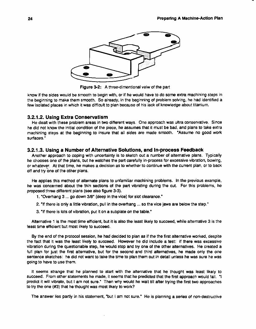
Figure 3-2: A three-dimentional veiw of the part
know if the sides would be smooth to begin with, or if he would have to do some extra machining steps in the beginning to make them smooth. So already, in the beginning of problem solving, he had identified a few isolated places in which it was difficult to plan because of his lack of knowledge about titanium.
3.2.1.2. Using Extra Conservatism He dealt with these problem areas in two different ways. One approach was ultra conservative. Since
he did not know the initial condition of the piece, he assumes that it must be bad, and plans to take extra machining steps at the beginning to insure that all sides are made smooth. "Assume no good work surfaces."
3.2.1.3. Using a Number of Alternative Solutions, and In-process Feedback Another approach to coping with uncertainty is to sketch out a number of alternative plans. Typically
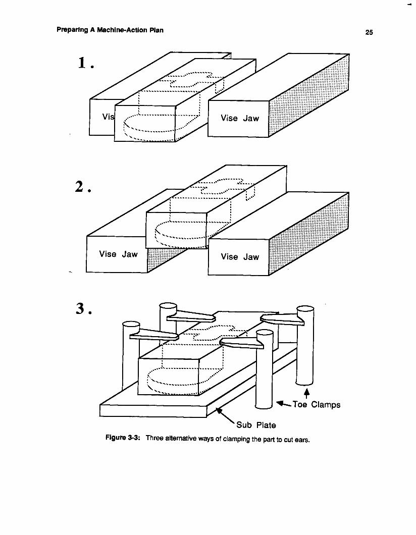
he chooses one of the plans, but he watches the part carefully in-process for excessive vibration, bowing, or whatever. At that time, he makes a decision as to whether to continue with the current plan, or to back off and trycone of the other plans.
He applies this method of alternate plans to unfamiliar machining problems. In the previous example, he was concerned about the thin sections of the part vibrating during the cut. For this problems, he proposed three different plans (see also figure 3-3).
1. "Overhang 3 ... go down 3/8" (deep in the vice) for slot clearance."
2. "If there is only a little vibration, pull in the overhang ... so the vice jaws are below the step."
3. "if there is lots of vibration, put it on a subplate on the table."
Alternative 1 is the most time efficient, but it is also the least likely to succeed, while alternative 3 is the least time efficient but most likely to succeed.
By the end of the protocol session, he had decided to plan as if the the first alternative worked, despite the fact that it was the least likely to succeed. However he did include a test: if there was excessive vibration during the questionable step, he would stop and try one of the other alternatives. He created a full plan for just the first alternative, but for the second and third alternatives, he made only the one sentence sketches: he did not want to take the time to plan them out in detail unless he was sure he was going to have to use them.
It seems strange that he planned to start with the alternative that he thought was least likely to succeed. From other statements he made, it seems that he predicted that the first approach would fail. "I predict it will vibrate, but I am not sure." Then why would he wait till after trying the first two approaches to try the one (#3) that he thought was most likely to work?
The answer lies partly in his statement, "but I am not sure." He is planning a series of non-destructive
Preparing A Machine-Action Plan 25
. .. . . . ... ,
2 . .... - .....
-
3 .
-
\Sub Plate Figure 3-3: Three alternative ways of clamping the part to cut eals.
4 %Toe Clamps
26 Preparing A Machlne-Action Plan
experiments to see how much he can "get away with," for this material. He wants to explore its limits. In the end, he may have to take the most conservative approach, but he wants to be sure that it is necessary. Furthermore, if he only tried only approaches he already knew would work, he would never learn anything new about about working with titanium. The information that he learns from his experiments not only allows him to complete the piece as quickly as possible, but helps him in planning future parts.
The experiments are non-destructive because he planned each alternative in such a way that it would be unlikely to ruin the workpiece if it failed. In this case, his safety measure was to leave extra stock on the piece. If vibration, cutting forces, or release of internal stresses caused the part's shape to change there would still be enough metal left that he could adjust the shape on future passes.
3.2.1.4. Using In-Process Feedback to Add Process Steps Another way to use in-process feedback is to adjust individual steps in the plan. In this particular part,
after planning how to make the cuts under the "thin sections" with minimal vibration, he next worried about whether removing all that material would cause the part to warp due to release of internal stresses. Since he had never worked with titanium, he did not know if this would be a problem or not.
The way he dealt with this problem was to first make a rough cut, leaving extra stock on the part, then in-process inspection was used to check for warping or bowing. If the part was satisfactory he proceeded with the rest of his plan, but if it was not satisfactory, then he adjusted his finishing cut to correct the bowing. These steps were laid out like a program during the protocol (see figure 3-4).
1. DO CUt-Out
2. Inspect
3. Finish cut step
4. Finish 1
5. Cut counterbore and slot to depth
Figure 3-4: The steps of a sample plan
Even for known materials, there is often uncertainty in the cutting process. He does not know how much the individual part will warp, or in what direction, since the stresses in each part are different. So these techniques for dealing with uncertainty may still have to be used, even when the material properties are known in advance.
3.2.1.5. Making Analogies to other materials. Despite the fact that neither of the two machinists used in the study had much practical experience with
titanium, they used their experience with other materials to make predictions about how titanium would behave. Both of them had read an article on titanium, which is quite a different from hands-on experience, and from this article they found that titanium tends to work-harden when the tool is allowed to idle in one place, and that it did not absorb heat well from the tools and hence tended to dull them. Using these bits of information, they made a guess that titanium would behave similarly to stainless steel and nickel alloys. "Titanium is like stainless, or all nickel alloys. Can't idle, can't use dull tools."
If a systematic method for making analogies between unknown materials and known materials could be uncovered, it would be a powerful planning heuristic.
Preparing A Machine-Action Plan 27
3.2.1.6. Summary of Planning with Incomplete Information The following list summarizes the methods for avoiding uncertainty. When there is uncertainty in the
domain knowledge, it may still be possible to make the first part right by: 0 Isolating uncertainties,
0 Planning with extra conservativeness,
Making a number of alternative (or back-up) plans,
0 Including in-process inspection as planning steps,
0 Using available information to make analogies to other materials.
Additionally, this protocol gives clues about the general information requirements of planning. 0 What type of in-process feedback can be used,
0 Where that information can be used in the plan,
How certain types of feedback information might be used to improve future performance.
It also exposes some of the process parameters that will be needed to make appropirate in-process measurements (e.g., the flatness of the part, the vibration levels).
These methods work well for new types of material, but they may not work for other more complex unknowns, such as, new types of fixtures. A new fixture, as mentioned earlier, may entirely change the way the problem is approached. It changes the types of feature interactions that one looks for, and it may change the grouping and ordering of the setups.
A new material, on the other hand, does not change the planning process drastically. The basic planning method is still the same, but there are isolated areas where it is uncertain how the material will behave. Discovering what machining problems are amenable to these methods is a possible area for future research.
3.2.2. Learning Program The goal of this project was to facilitate the exapansion of the Machinist program’s domain knowledge,
by aiding in knowledge acquisition and by automatically formulating new heuristics from newly acquired data.
Over course of the Machinist project, it has become evident that one of the biggest problems in making such a system practical, is incorporating large amounts of expert knowledge. The problem is both that the information is difficult to acquire and that a very large amount of it is needed. Furthermore, once the knowledge is acquired, the underlying technology may change, and different rules will be needed: new flexible fixtures may devised, or the basic machine capabilities may change. Changing or adding to the system is a long and laborious task when done by human knowledge engineers. To speed up this process, the Machinist program must aid in the acquisition and maintenance of its own knowledge.
Knowledge acquisition is very laborious because the expert cannot typically report his knowledge in the form of rules that can be encoded directly into an expert system. When given a particular part, he can devise a plan to manufacture it and he can give reasons for specific decisions used in that plan, but he cannot usually generalize those deasions into rules that apply to all parts. Thus, the knowledge engineer must go through a cycle in which he observes machinists working on many individual problems, and then induces rules to describe their general behavior. Next the knowledge engineer must think up appropriate programming representations for the rules and code them. Finally, the rules must be tested by running them on a variety of cases, and showing their behavior to experts. Note that he shows the expert how the
28 Preparing A Machine-Action Plan
rules behave in a variety of cases, rather than showing just the rules. This process is summarized in figure 3-5.
1. Present the expert with a number of examples.
2. Study the solutions generated by the expert.
3. induce a rule that will give the same solution as the expert.
4. Devise a programming representation for that rule.
5. Test the rule by presenting the program with a number of new examples.
6. Have the expert evaluate the performance of the new tule.
7. Go to 1.
Figure 3-5: Method of Protocol Analysis
If the system could aid in this process, it would help to expand the system’s domain knowledge dramatically and make it more adaptable to technology changes. The Knowledge Engineer program, which runs on the TI Explorer helps the expert to enter information about how different metals behave under a variety of circumstances.
To use the program, an expert machinist sits down in front of the terminal. A block of a some material (e.g, aluminum, steel, titanium, etc.) is drawn on the screen. its height, width, and depth are randomly chosen (see figure 3-6). The block is shown clamped in a 2 inch high table vise, and a small ruler and is drawn on the side. Both of these graphical objects act as references and help the machinist get an idea of the draying’s scale. The block’s dimensions are also printed in the comer so he can double check his visual estimate of the size.
Height: 5.25 Width: 4.50 Length: 6.75
3
2 ;i 0 1
Figure 3-6: A block of random height, width and depth, drawn by the Knowledge Engineer Program.
The machinist is asked if face cutting is safe with the current dimensions (see figure 3-6). If not, the
Preparlng A Machlne-Actlon Plan 29
mouse can be used to change the height of the block (and only the height). By clicking once on the front of the block he can adjust the height dimension according to the mouse location. When the block looks like it is at a “safe height,” the mouse can be used to click on the “SAVE” box in the upper right of the screen: the height, width, depth and material of the block are saved in a file, and a new block of random dimensions is drawn on the screen.
Data on several different types of cuts can be collected with this program. In addition to just making a face cut on the block, the machinist can also specify to the program to make a slot of varying dimensions, that can either run from side to side or from front to back of the block. The direction of the slot makes a difference in how the block will behave during cutting. Other types of cuts and other ways of clamping the part can be added in the future.
Already this has increased the rate at which data can be collected from the expert. It used to take about 5 minutes to collect one datapoint describing the metal, when examples had to be set up by hand. It now take approximately 3 seconds to collect the same type of datapoint.
The problem now is what to do with that data. It is still difficult to extract rules and trends from this data. Several methods for automatically extracting that information and forming it into rules are being investigated .
Part of the problem in this case is that simple known statistical methods will not work. First of all, the behavior of a metal may sometimes be controlled by more than one function. In the example used above, one can look at the graph of the data (see figure 3-7), and easily see that there appear to be two separate functions limiting the height of the block. It turns out that those functions are vibration and stability, as will be discussed latter. Although it is easy for a human to separate functions by eye, it is not so easy to do it automatically with a computer. Currently, there are no satisfactory statistical methods for breaking the two functions apart (Swamy and Metha 1975). If the functions could be separated, it might be possible to use standard linear regression techniques to extract each trend.
Second, even if the functions could be separated, they are not necessarily linear, and non-linear functions cannot be easily extracted automatically. Typically, they are found by an iterative method in which the statistician chooses a function at each step in the function to make it approximately linear.
One possible solution might be to do a piece-wise approximation of the functions. It could be done as follows: after few data points have been entered, the program does a linear regression on the data. On the next block presented to the machinist, the program no longer randomly chooses the height, but instead uses the regression line to estimate what the maximum height allowed should be, for the particular width and depth that it has randomly chosen. If the machinists does not correct the program’s guess in the next few trials, then that is a good indication that the program has estimated the function correctly, and the program is done collecting data.
However, this will not usually be the case, unless the metal’s behavior follows a simple linear function. If the machinist corrects the program’s guesses repeatedly then the program’s approximation is probably not very good. So the program divides the graph into two or more parts and does a linear approximation on each part. If in any one of these new regions, the program’s guess needs to be corrected then that region is in turn divided into smaller parts.
By using this method, areas of the graph that curve or change sharply naturally get divided into many small lines and areas that are relatively straight would be approximated by a single long line. If each region gives a good estimate of a small area, it will not be necessary separate the function into multiple functions, or to worry about non-linear curves.
Unfortunately, there are really two separate functions controlling the height of the part: vibration and
30 Preparing A Machlne-Actlon Pian
- Stability Function -
- Vibration Function
-
- is 1.75" high - 1 *I-
0" I I I I I I 1 II 2 II 3 II 4 V I 5 II 6 II
JVicjQ bf Peice -Figure 3-7: A ra h of the wi h o
stability. (In other situations different functions may come into play.) Knowing something about these functions might be important to attaining a deeper understanding of the machining process.
e e part against maximrm allowable height De& orpiece fixed at six inches.
Another simple solution would allow the machinist to separate the function into multiple functions by having the program ask him to identify the reasons for his choices. For instance, if the program shows him a block that is .5 inch wide and 4 inches high, he will say that he is worried that the part will vibrate. If the program shows him a block 5.5 inches wide and 8 inches high he will say that now he is worried that the part will not be stable. In other words, he is worried that the part will lever itself out of the vise during a cut, if it is too tall. After a little more questioning, it becomes clear that when the part is between 0 and 1 inch wide the machinist is worried about vibration, and it is between 1 and 6 inches wide he is worried about stability. The graph in figure 3-7 confirms this.
The program can question the machinist for a variety of datapoints in the graph to get a good idea of how many functions there are in the graph, what they are, and where they cross over. Once the program knows where they cross over, it can divide the graph into separate functions at those points, and do a regression on each individual function.
3.3. FUTURE WORK The previous sections each touched on some of the limitations of the current Machinist system, and
suggested areas of investigation for solving these problems. The goals for future work proposed in these sections can be summarized as follows:
Continue protocols to investigate ways in which machinists: acquire new domain information,
Preparing A Machlne-Action Plan 31
use in-process feedback to guide them through uncertainty.
0 Investigate areas for planning with incomplete knowledge (e.g., new materials, new tools,
Incorporate these findings into the Machinist program.
new fixture types, etc.).
The net result of this work will be to: 0 Expand the range of parts that can be used by the machinist program.
Allow the program to proceed with only partial knowledge of the situation.
.Allow the program to incorporate in-process feedback, both for avoiding errors, and for
Extend the flexibility of the program.
improving future performance.
The test parts provided by Pratt and Whitney have indicated a strong need for these improvements. However, there are additional problems. Six of the seven parts of the provided designs are designed to start machining with a casting instead of a piece of bar-stock. This single fact may question our basic method of generative planning (Le. starting from bar-stock and building up with primitives to the final part geometry), because the casting is often a near-net shape. In the case of castings, it may be easier to accomplish our goals by a kind of variant process planning that would “modify” the casting description into the final geometry by reasoning directly about finish cutting. Despite any simplifications made possible by starting with near-net shapes, castings will still have to be postively located in fixtures and this could be extremely difficult with generic clamping devices.
3.4. References Hayes, C.C. 1987a. Planning in The Machining Domain: Using Goal Interactions to Guide Search,
Masters Thesis, Mellon College of Science, Carnegie Mellon, April.
Hayes, C.C. 1987b. Using Goal Interactions to Guide Planning: The Pmgram Model, Robotics Institute, Carnegie Mellon, CMU-RI-TR-87-10.
Hayes, C.C. 1987c. Using Goal Interactions to Guide Planning, The Sixth National Conference on Artificial Intelligence, Seattle WA, July, Vol 1 ., pp. 226228.
Swamy, P.A. and Metha, J.S. 1975. Bayesian and Non-Bayesian Analysis of Switching Regressions and of Random Coefficient Models, Journal of The American Statistical Association, Vol. 70, No. 351, pp. 593-602.

32 Preparlng A Machine-Action Plan
lnvestlgatlons on the Use of Sensors In Machining 33
4. Investigations on the Use of Sensors in Machining
4.1. Introduction Achieving the goal of unmanned machining of one-of-a-kind, geometrically complex parts from hard-to-
machine alloys will require extensive and sophisticated application of sensing technology beyond the current state-of-the-art. Individually sophisticated sensors, operating in real time, are required, together with the ability to integrate input from multiple sensors of different types into a coherent sensory experience of the machining environment.
In this chapter, we report on several preliminary investigations on the use of sensors in machining. The most impressive sensing system known is the human one; so we have studied the way humans use their sensing in the machining environment. Our aim is not to be able to duplicate what humans do, in detail, but simply to see what useful lessons can be learned from this most skilled of all known expert sensing devices. We have also included in this chapter a brief report on four case studies done in our laboratory, as well as some general considerations on the design of visual sensing systems.
4.2. Somatic Knowledge Engineering Skilled craftsmen and repair technicians are experts in handeye manipulation tasks and sensor based
monitoring skills. This section describes some characteristics of such craftsmanship and some of the activities of an expert machinist who plans and supervises the fabrication of a complex three-dimensional metal part on a computer controlled milling machine. The motivation of this work is to automate such an activity so that the machine tool can run completely unattended in a future factory environment. Extending the generally recognized technique of knowledge engineering for expert systems, craftsmen are studied during the enaction of their daily activities at the machines. In our research group, we have begun to carry out the knowledge engineering work involved in understanding and then later mimicking the broad spectrum of tasks that human machinists carry out.
4.2.1. Steps in Human Machining Figure 4-1 shows a simple chronology of the tasks that are involved in onsof-a-kind machining. The
nine labels shown in the figure (i.e., plan, NC program, fixture setup, part setup, tool setup, phantom, rough, finish, and inspect) are self-explanatory, except for the description of the machining operation which perhaps requires some clarification. An interesting routine that the machinists go through during the machining of one-of-a-kind parts is to carry out the phantom, roughing and finishing passes. During the phantom pass, no metal is cut. The machinist carries out a trial cut in air immediately above or around the stock that is awaiting the cutting operation. During this phantom pass, he verifies and evaluates the performance of the NC program that he prepared earlier. The machinist carries out a spatial mapping from this cutting in air to the positions that he can see the tool will be in in future cutting operations. He is therefore checking that the programmed moves are generally correct and that there will be no dangerous interactions between the tools and the fixtures. If all goes well during the phantom pass the machinist will then begin to cut the metal. During the roughing cut, the rates of metal removal are relatively high and he is not particularly concerned with the quality of the surface finish on the part. He is acquiring the broad features of the part and removing stock to the almost finished dimensions. Incidentally, a skilled craftsman would never attempt to get the finished dimensions immediately. He has to study the machine tool during the roughing cut and insure that there is no backlash in the machine tool drives, that the fixtures are not moving, that the tools are not deflecting, and, in general, that there are no other aspects of the machining environment that could lead to a poor finished product. It is only when the machinist has created a "roughed out" part that is relatively close to the final part dimensions that he will commit to the finishing cuts and obtain the final desired component. During these cuts, he will be much more concerned with the exact sizes and the quality of the surface finish.
.
10
h
u) C a C
c .-
). -
2
34 investigations on the Use of Sensors in Machining
I I I I I k k I I I I I I I I
Active, EXp8Cfaflf US8 k : Passive Use I Active
Recall I I I n n
Setup Machining Quality Assurance - - - - - - - _ _ _ _ _ _ _ - a 7 . - _ _ - --: \
- - - - _ .\ _ _ - - _ _ _ _ _ _ _ _ - - - - - - - - n 1 . 0 0 . c1 P n . CI * * *
Plan .W (.( Fixture Part Tool (.( Phantom;' Rough 0 .( Finish Inspect ;' 0 b
* .( Program; Setup ; Setup ;' Setup .' 0 * 0 * 0
1 4 * . . 0 0 0 0
0 0 0 * 1 * 0 + * . 0 . 0 * 0 0 1 0 * , 0 * . *
t 0 0 *
Feedback Experience
Figure 4-1: Nine stages in the machining of a "one-of-a-kind" metal part
4.2.2. Human Sensory Monitoring The replacement of the human craftsman in the future will require a blend of sensor hardware,
diagnostic software, and the correct control strategies. In the course of studying the machinist's actions, we have analyzed the sensory skills that the machinist uses. While setting up tools, he relies heavily on visual and tactile feedback. During the monitoring of machining phases, the tactile sense is used infrequently and limited to a few ad hoc touches of a machine tool fixture to judge vibrations. During machining, visual monitoring and auditory monitoring were the two important sensory elements of one-of- a-kind machining but these were used to different degrees in different parts of the process.
Figure 4-2 is an elaboration of figure 4-1 showing how the visual monitoring of the craftsman is used over time. We emphasize that this graph is extremely qualitative in nature. The graph shows a rough estimate (on a scale from 0 to 10) of how intensively a particular sensory skill is being used during different phases of the machining process.
Figure 4-2: The use of visual monitoring during machining
Investigations on the Use of Sensors in Machining 35
During setup, the craftsman makes extensive use of visual monitoring. He is checking the alignment of fixtures and tools and carefully positioning stock in fixtures. The next stage, the execution of the phantom pass, is a "hypothesis and test" in air, where spatial reasoning based on visual data is extremely Important to the success of the operation. During this evaluation, the machinist is undertaking a variety of internal dialogues, where the answers are based on his visual observations (see figure 4-2).
~~~ ~ ~ ~ ~ ~ ~ ~
Question : Response:
Question : Response:
Question :
Response:
Did I create errors in the NC program? Step through the NC program in single block mode and visually check to see that the tool moves over the part in the expected way. Did I cause potential collisions between tools, parts, and fixtures? Cycle through the various cuts and visually assess, again using spatial mapping, that the cutter parts are safe and correct. Did I set the correct cutting speeds and feed rates for the particular fixture, stock, or tooling configurations? Run the cutting tools in air and relate to previous experience on the expected chip formation patterns when machining begins.
~~~~~ ~~
Figure 4-3: Example internal dialogue
Obviously, there are many other questions posed during such inner dialogues. The term "design dialogue" has been coined for such work and it becomes an important tool in the development of an expert system for machining. This point is discussed further in section 4.2.3.
Dwng the roughing passes, the machinist still uses visual monitoring of the scene but to a lesser extent than during the phantom pass. As shown in figure 4-2, his use of visual sensing begins to be more passive. He will continue to monitor using vision but will be expecting fewer things to go wrong. By contrast, during the setup phase and the phantom pass, he will be expecting difficulties and using his vision sense in a very active way. Again, such labels are rather qualitative and intuitive but they have been applied to these phases, as shown in the figure, in order to bring out the different uses of the sensor. In day to day living, humans use their senses in such a way. Often we are not actively using our visual capability, but, nonetheless, will be alerted if an unexpected intruder or event enters our visual field. In other situations, e.g., searching for a lost object, our visual sensing is much more active. When we are inspecting a detailed object, or searching for a fault, our vision is extremely focused and active.
As the roughing and finishing stages of machining occur, the machinist begins to rely more on his auditory sense for monitoring. This final development is shown in figure 4-4, superimposed on the earlier figures. During the roughing phases, when chips are being produced, the machinist hears the sounds that the tool and part and fixture make and relates them to his knowledge of the quality of the associated machining. During the finishing stages, it is very difficult to see the precise interactions between the tool and the part; he will use his visual sense to monitor the quality of the finished component, so vision is still used to some extent. However, for other interactions, including tool breakage and the quality of fixturing, the machinist will depend on his auditory sense to a high degree. In addition, it should be noted that if the batch sizes are larger than 1, then the auditory monitoring becomes even more important as an overall monitoring strategy of the manufacturing picture. This is how a machinist can run several machines at the same time. Although he will be attending to one machine in particular he will also be "keeping an ear out" for the activities on the other machines. There are even factory situations where machinists do not seem to be particularly active and are talking among themselves; however, they will also be tuned in to their equipment and, if they hear a new sound, will quickly retum to the details of machining or of diagnostic and recovery work. Again, we emphasize that figure 4-4 is extremely qualitative.
Investigations on the Use of Sensors in Machining
Agum 4-4: The use of visual and auditory monitoring during machining
Despite the tentative nature of these results, it is interesting to think about the way in which vision and auditory monitoring are used in different phases. For example, figure 4-5 presents an estimate of the use of visual and auditory monitoring during the roughing pass.
Monltoting straoegy
observe the influence and speed and feed on chip type burr creation surface finish
monitor tool fixturing interactions during roughing normal operating unforeseen accidents
monitor tool integrity during a cut out of cut
monitor effectiveness of cutting fluid
monitor tool home positions and clearance plane positions
M K o r y visual Intensity [O-101 lntenslty [O-1 01
10 9 6
9 1
2 10
9
10
0 1 2 (tacti le=2)
1 9
a 0
1
0
Figure 4-5: Visual and auditory monitoring during roughing pass
While the monitoring strategies described above keep a particular cutting operation in good order, the
Investigations on the Use of Sensors In Machining 37
experiences obtained also remain with the machinist for future work. Every time the expert machinist machines, he adds to his database of sensory awareness. This is why the feedback, shown contributing to the original planning process, has been emphasized in figure 4-1. Of course, the sensory information is not used in its raw form. The machinist is always comparing and contrasting the current information with his past experience. This shows a need to move from a qualitative to a quantitative understanding of the sensory information. The first step in doing this within the knowledge engineering and expert system environment is to go into further depth in the sensory evaluations through design dialogues.
4.2.3. The Craftsman's Internal Design Dialogues In carrying out knowledge engineering work for machining environments, it is not sufficient to merely
observe machinists at work and then mimic their activities. The fact that a machinist uses a particular sensor to evaluate a machining condition does not mean that the automated mechanical system will use the same sensor. There may be simpler or more robust artificial sensors that make a better choice for an automated environment. It is more important to focus on the question "What is the intelligent system trying to evaluate?" For example, when the intelligent human machinists examine the tool after a particular cut, they are not "just looking" at the tool to see if it is in a satisfactory state. Generally they are asking much more complex questions. In this example, an important question they are considering is "Is there enough life left in this cutting tool to machine the next part all the way through without stopping to change tools?'. Machinists will, at all costs, try to avoid a tool change in the middle of a cut. Not only does changing a tool involve frustrating readjustments of tool positions during the tool change, but almost always leaves a rub mark on the part where one tool has deteriorated and the other one has begun cutting.
Experience has shown that turning tools and milling cutters are approaching the end of their useful life when there is 0.03 inch of flank wear on the cutting edge of the tool. After some years of operating a machine tool, machinists become surprisingly competent at being able to estimate small dimensions such as this, and the trained eye can see within 220% where the tool is in its life expectancy. In installing a computer vision system to analyze the life of cutting tools, design dialogue information such as this gives much guidance to the vision engineer about to design and install a system. The design dialogues set the scope of the task and focuses on the precise area that has to be examined. They set the qualitative boundaries of the length of measurement of interest and how accurately it has to be made. The dialogues also suggest ways which lighting and the mechanical part of the system must be arranged and give some indication of how often the measurement should be made.
In summary, the design dialogue focuses on the real questions of importance for designing unmanned manufacturing systems, rather than directly mimicking human behavior without giving overall thought to the broader impact on the manufacturing process or the economic issues at stake.
4.2.4. Discussion This section has reviewed some initial ideas in somatic knowledge engineering within the context of
machine tool monitoring. In our general study of manufacturing and machining operations, there have been other instances where it has been important to learn about the way in which the human body responds to the environment. For example, during the development of our flexible and autonomous fixturing project, we equipped machinists with instrumented torque wrenches to see how tight they clamped the individual toe-clamps during fixturing. These values were useful in programming our automated system (Englert and Wright, 1986). In other manufacturing processes such as the disc grinding of a metal component with an industrial robot, we again found it necessary to study the typical value of force exerted by a human craftsman prior to robot programming (Cutkosky and Wright, 1986). The study of the robot grinding operation brought out many nuances of the somatic knowledge engineering work. For example, it was found that humans change their grinding style as the work
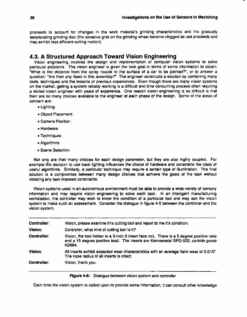
38 Investigations on the Use of Sensors in Machinlng
proceeds to account for changes in the work material’s grinding characteristics and the gradually deteriorating grinding disc (the abrasive grits on the grinding wheel become clogged as use proceeds and they exhibit less efficient cutting motion).
4.3. A Structured Approach Toward Vision Engineering Vision engineering involves the design and implementation of computer vision systems to solve
particular problems. The vision engineer is given the task goal in terms of some information to obtain: “What is the distance from the spray nozzle to the surface of a car to be painted?”, or to answer a question: ”Are their any flaws in this assembly?” The engineer constructs a solution by combining many tools, techniques and the lessons of previous experiences. Even though there are many vision systems on the market, getting a system reliably working is a difficutt and time consuming process often requiring a skilled vision engineer with years of experience. One reason vision engineering is so difficult is that their are so many choices available to the engineer at each phase of the design. Some of the areas of concern are:
0 Lighting
0 Object Placement
0 Camera Position
0 Hardware
0 Techniques
0 Algorithms
0 Scene Selection
Not only are their many choices for each design parameter, but they are also highly coupled. For example t6e decision to use back lighting influences the choice of hardware and constrains the class of useful algorithms. Similarly, a particular technique may require a certain type of illumination. The final solution is a compromise between many design choices that achieve the goals of the task without violating any task imposed constraints.
Vision systems used in an autonomous environment must be able to provide a wide variety of sensory information and may require vision engineering to solve each task. In an intelligent manufacturing workstation, the controller may wish to know the condition of a particular tool and may ask the vision system to make such an assessment. Consider the dialogue in figure 4-5 between the controller and the vision system.
Controller: Vlslon: Controller:
Vision, please examine this cutting tool and report to me it’s condition. Controller, what kind of cutting tool is it? Vision, the tool holder is a 3-inch 6 insert face mill. There is a 5 degree positive rake and a 15 degree positive lead. The inserts are Kennametal SPG-532, carbide grade K2884.
All inserts exhibit expected wear characteristics with an average flank wear of 0.01 5”. The nose radius of all inserts is intact.
Vlsion:
Controller: Vision, thank you.
~ ~~
flgure 4-6: Dialogue between vision system and controller
Each time the vision system is called upon to provide some information, it can consult other knowledge
. Investigations on the Use of Sensors in Machining 39
bases containing task specific information and engineer a solution to solve the problem. To achieve this scenario requires an expert vision engineering system that is able to design vision solutions based on task specific knowledge and characteristics.
The goal of this research is to address both of the these concerns: 1. Develop guides for the novice engineer not expert in applying computer vision, that will
assist in the design process. A structured paradigm will also be developed that is suitable for many industrial applications.
2. Develop a framework for the representation and use of knowledge about computer vision, that autonomous systems could use when engineering vision tasks.
4.4. Human Use of Vision during Machining In an effort to determine potentially valuable applications of vision to the IMW, we examined video
tapes of a human machinist machining a part and identified those tasks in which vision was employed in a critical way.
A couple of things should be noted about this study. First, when the tapes were made, no one imagined that they would be used in this way. Second, the tapes used in the study were made over widely spaced intervals; so the machinist had become comfortable with the filming situation by the time the later tapes were made. We have grouped vision-related tasks chronologically, according to whether they occurred before, during, or after the actual machining phase. In fact, some tasks occur in more than one phase, but we have only listed them once.
4.4.1. Preprocess
orientation tasks were identified in this phase. These included: Tool Setup
The items in this section are vision intensive tasks preliminary to cutting metal. Both measurement and
The machinist used vision to guide the tool to close proximity to a material of known thickness. The measurements were done by touch and included:
Gauging tool length
Gauging vertical tool placement
0 Coordinate System Determination The machinist used an edge finder to set the zero point of the machine tool coordinate system relative to the part. The edge finder’s response to touching the part was a visible off-axis deflection of a ring. The choice of this device, because it was more accurate than an electronic touch probe that was available, put vision in a critical role. The tasks in this phase included:
Identifying initial orientation of the stock
Guiding edge finder tool
Detecting edge finder contact with part
Validating edge finder results
4.4.2. In-Process During the cutting phase, the machinist used vision, as well as his other senses, to monitor the
progress of the machine and the state of the machining environment. He was watching for both the expected and the unexpected, including the following:
40 Investigations on the Use of Sensors in Machlnlng
0 Confirmation The machinist visually verified his actions and carefully watched the operation of the programmed machine tool to make sure the program was doing what was intended. In one instance he was able to bring the system to an emergency stop before an erroneous instruction was executed and saved scraping the part. Confirmation tasks included:
Verifying part orientation and fixturing
Verifying proper tool selection
Verifying general system functioning (e.g., tool rotating, cutting fluid activated)
Verifying proper programming by visually tracking and predicting the tool path
Verifying the extent of drilling and cutting
0 Safety The machinist, without thinking about, was continually determining that the work volume was functioning safely, e.g., that the spectators were safely out of the way.
4.4.3. Postprocess
tasks. These included: Once the cutting phase was complete, the machinist used his visual abilities for a number of inspection
0 Dimensional Analysis The machinist used vision during both in-process and postprocess measurement. Tasks in this category included:
Guiding successive approximation to final tolerances
Inspecting the part after the job was complete
0 Feature Analysis During both the preprocess and postprocess phases, the machinist used vision for qualitative measurement of features such as:
Holes
Overall shape
Surface finish (e.g., rolled, cut)
0 Maintenance The machinist used vision for maintenance functions such as:
Monitoring tool wear
Chip monitoring
4.5. Five Case Studies Five example applications are used throughout this research to illustrate key points and to serve as test
cases for the application of certain ideas. Four of the applications have been investigated in the laboratory and the fifth is included as a thought experiment.
4.5.1. Measurement This application has not been specifically investigated in the lab, although various measurement
experiments have been conducted. An example application involving measurement would be determining the distance between various holes in a manufactured component. The important aspect of this example application is that it emphasizes obtaining a high accuracy dimensional measurement.
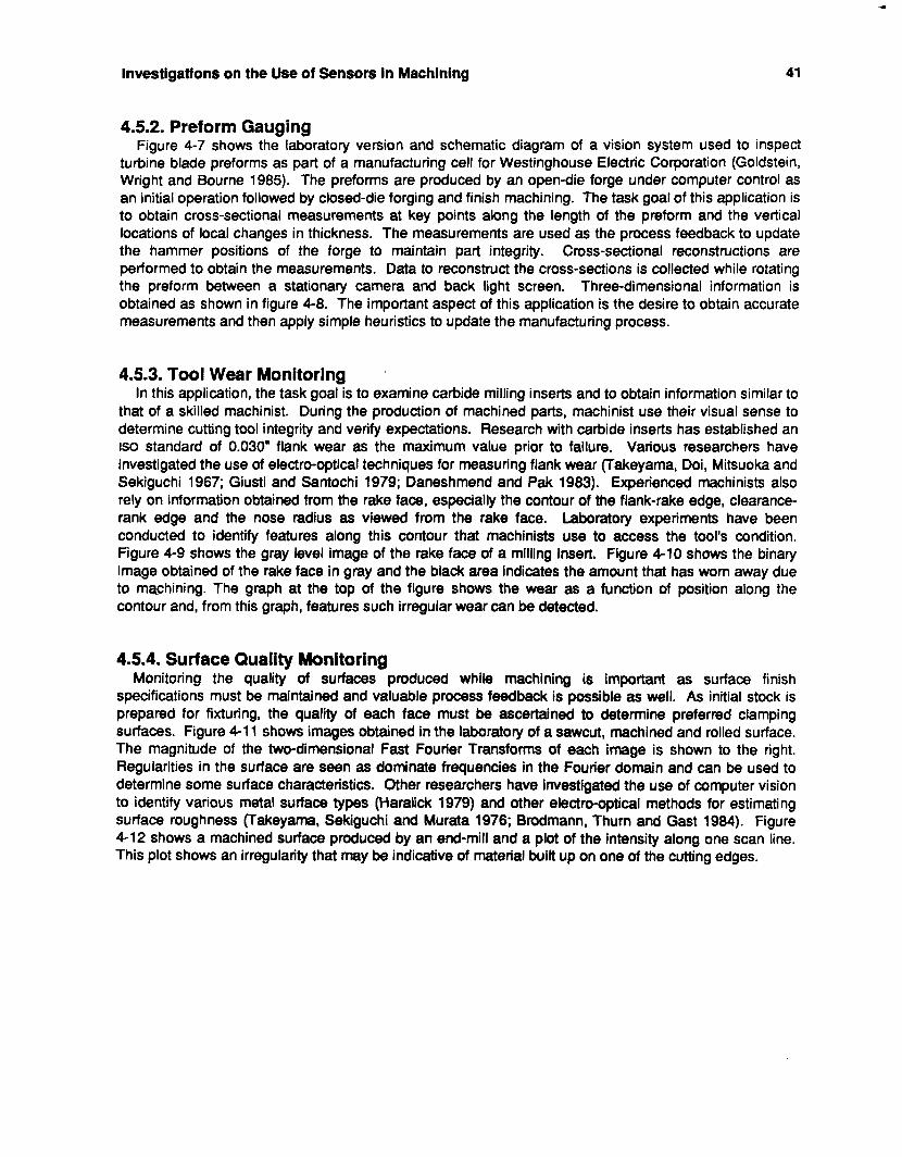
Investlgatlons on the Use of Sensors in Machining 41
4.5.2. Preform Gauging Figure 4-7 shows the laboratory version and schematic diagram of a vision system used to inspect
turbine blade preforms as part of a manufacturing cell for Westinghouse Electric Corporation (Goldstein, Wright and Bourne 1985). The preforms are produced by an open-die forge under computer control as an initial operation followed by closed-die forging and finish machining. The task goal of this application is to obtain cross-sectional measurements at key points along the length of the preform and the vertical locations of local changes in thickness. The measurements are used as the process feedback to update the hammer positions of the forge to maintain part integrity. Cross-sectional reconstructions are performed to obtain the measurements. Data to reconstruct the cross-sections is collected while rotating the preform between a stationary camera and back light screen. Three-dimensional information is obtained as shown in figure 4-8. The important aspect of this application is the desire to obtain accurate measurements and then apply simple heuristics to update the manufacturing process.
4.5.3. Tool Wear Monitoring In this application, the task goal is to examine carbide milling inserts and to obtain information similar to
that of a skilled machinist. During the production of machined parts, machinist use their visual sense to determine cutting tool integrity and verify expectations. Research with carbide inserts has established an is0 standard of 0.030" flank wear as the maximum value prior to failure. Various researchers have investigated the use of electro-optical techniques for measuring flank wear (Takeyama, Doi, Mitsuoka and Sekiguchi 1967; Giusti and Santochi 1979; Daneshmend and Pak 1983). Experienced machinists also rely on information obtained from the rake face, especially the contour of the flank-rake edge, clearance- rank edge and the nose radius as viewed from the rake face. Laboratory experiments have been conducted to identify features along this contour that machinists use to access the tool's condition. Figure 4-9 shows the gray level image of the rake face of a milling insert. Figure 4-10 shows the binary image obtained of the rake face in gray and the black area indicates the amount that has worn away due to machining. The graph at the top of the figure shows the wear as a function of position along the contour and, from this graph, features such irregular wear can be detected.
4.5.4. Surface Quality Monitoring Monitoring the quality of surfaces produced while machining is important as surface finish
specifications must be maintained and valuable process feedback is possible as well. As initial stock is prepared for fixturing, the quality of each face must be ascertained to determine preferred clamping surfaces. Figure 4-1 1 shows images obtained in the laboratory of a sawcut, machined and rolled surface. The magnitude of the two-dimensional Fast Fourier Transforms of each image is shown to the right. Regularities in the surface are seen as dominate frequencies in the Fourier domain and can be used to determine some surface characteristics. Other researchers have investigated the use of computer vision to identify various metal surface types (Haralick 1979) and other electro-optical methods for estimating surface roughness (Takeyama, Sekiguchi and Murata 1976; Brodmann, Thurn and Gast 1984). Figure 4-12 shows a machined surface produced by an end-mill and a plot of the intensity along one scan line. This plot shows an irregularity that may be indicative of material built up on one of the cutting edges.
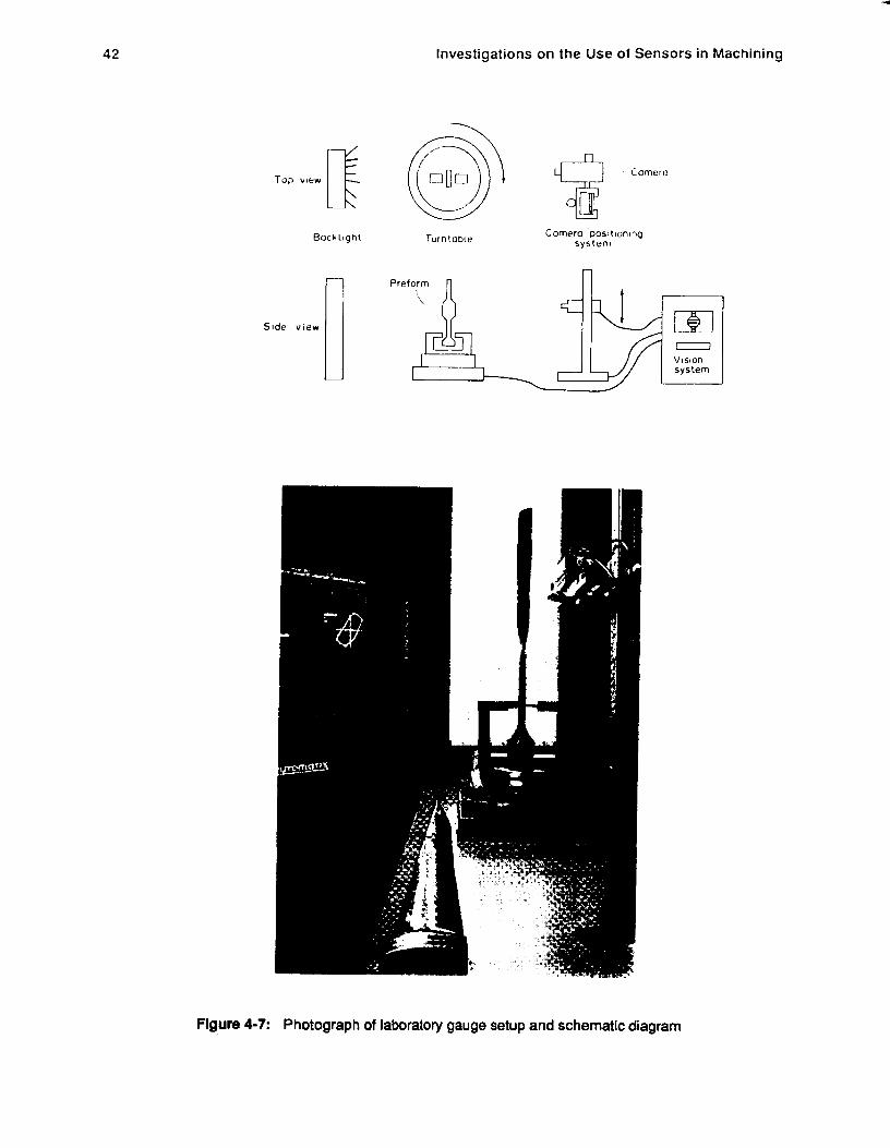
42
E Top view
Rock l ight
I Side v i e w
Investigations on the Use of Sensors in Machining
rurntotxe
i omero
Comero positlon4ng system
Flgure 4-7: Photograph of laboratory gauge setup and schematic diagram
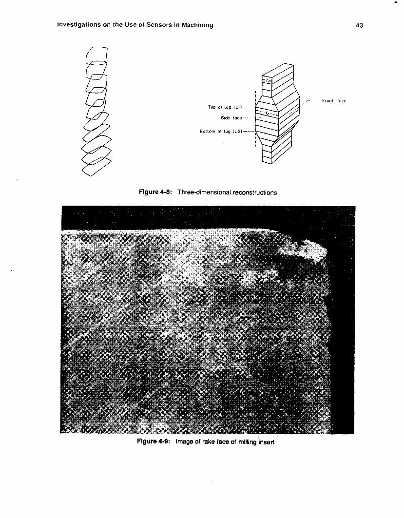
Investigations on the Use of Sensors in Machining
Top of tug ( L I )
Side foce-
Bottom of lug (L2)-
Figure 4-8: Three-dimensional reconstructions
1
43
Front face
Figure 4-9: Image of rake face of milling'insert
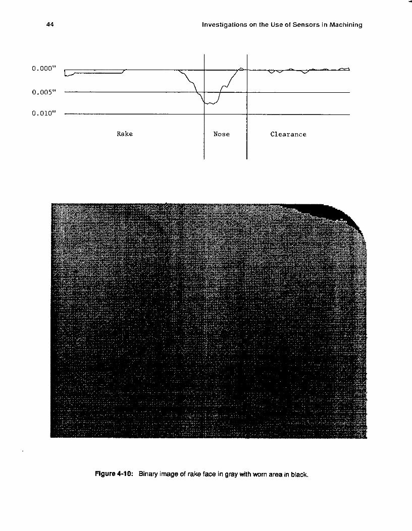
44 Investigations on the Use of Sensors in Machining
0.000"
O.OO5"
0.010"
Rake
7 J
Nose Clearance
Flgure 4-10: Binary image of rake face in gray with worn area in black.
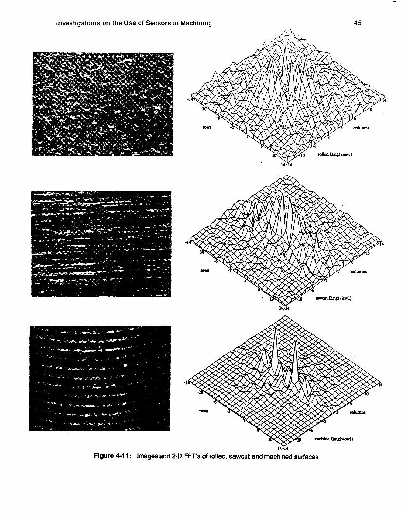
Investigations on the Use of Sensors in Machining
I
45
V 14:14
I434 flgure 4-1 1: Images and 2-D FFT's of rolled, sawcut and machined surfaces
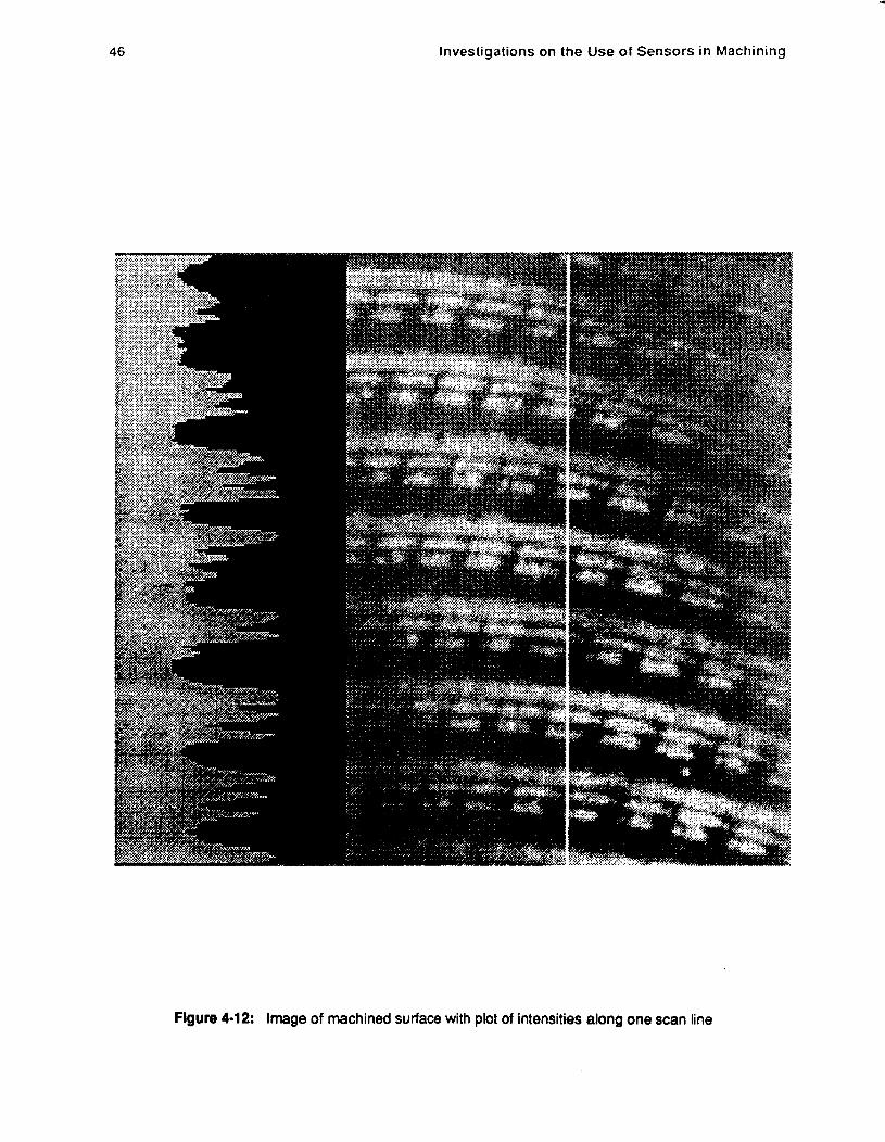
46
1
investigations on the U s e of Sensors in Machining
Figure 4-12: Image of machined surface with plot of intensities along one scan line
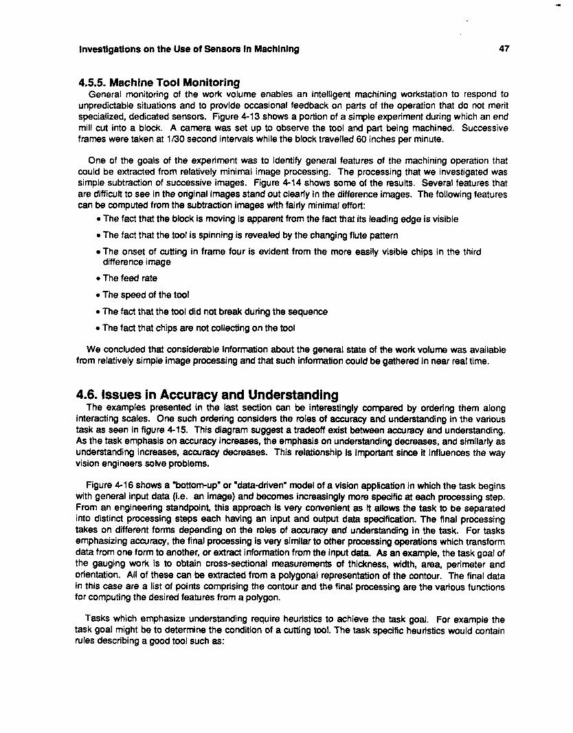
Investigations on the Use of Sensors in Machining 47
4.5.5. Machine Tool Monitoring General monitoring of the work volume enables an intelligent machining workstation to respond to
unpredictable situations and to provide occasional feedback on parts of the operation that do not merit specialized, dedicated sensors. Figure 4-13 shows a portion of a simple experiment during which an end mill cut into a block. A camera was set up to observe the tool and part being machined. Successive frames were taken at 1/30 second intervals while the block travelled 60 inches per minute.
One of the goals of the experiment was to identify general features of the machining operation that could be extracted from relatively minimal image processing. The processing that we investigated was simple subtraction of successive images. Figure 4-14 shows some of the results. Several features that are difficult to see in the original images stand out clearly in the difference images. The following features can be computed from the subtraction images with fairly minimal effort:
0 The fact that the block is moving is apparent from the fact that its leading edge is visible
0 The fact that the tool is spinning is revealed by the changing flute pattern
The onset of cutting in frame four is evident from the more easily visible chips in the third
0 The feed rate
0 The speed of the tool
0 The fact that the tool did not break during the sequence
0 The fact that chips are not collecting on the tool
difference image
We concluded that considerable information about the general state of the work volume was available from relatively simple image processing and that such information could be gathered in near real time.
4.6. Issues in Accuracy and Understanding The examples presented in the last section can be interestingly compared by ordering them along
interacting scales. One such ordering considers the roles of accuracy and understanding in the various task as seen in figure 4-15. This diagram suggest a tradeoff exist between accuracy and understanding. As the task emphasis on accuracy increases, the emphasis on understanding decreases, and similarly as understanding increases, accuracy decreases. This relationship is important since it influences the way vision engineers solve problems.
Figure 4-1 6 shows a "bottom-up" or "data-driven" model of a vision application in which the task begins with general input data (Le. an image) and becomes increasingly more specific at each processing step. From an engineering standpoint, this approach is very convenient as it allows the task to be separated into distinct processing steps each having an input and output data specification. The final processing takes on different forms depending on the roles of accuracy and understanding in the task. For tasks emphasizing accuracy, the final processing is very similar to other processing operations which transform data from one form to another, or extract information from the input data. As an example, the task goal of the gauging work is to obtain cross-sectional measurements of thickness, width, area, perimeter and orientation. All of these can be extracted from a polygonal representation of the contour. The final data in this case are a list of points comprising the contour and the final processing are the various functions for computing the desired features from a polygon.
Tasks which emphasize understanding require heuristics to achieve the task goal. For example the task goal might be to determine the condition of a cutting tool. The task specific heuristics would contain rules describing a good tool such as:
48
-
Investigations on the Use of Sensors in Machining
Flgure 4-1 3: In-process machine tool monitoring experiment
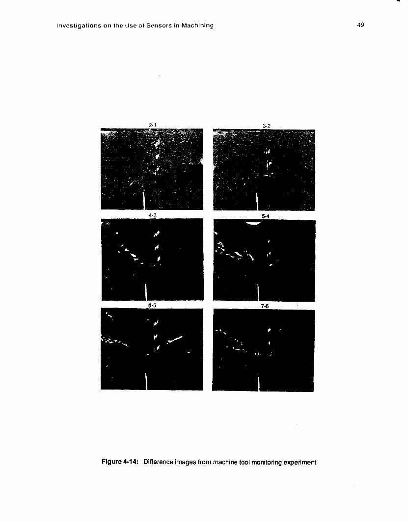
Investigations on the Use of Sensors in Machining 49
Figure 4-14: Difference images from machine tool monitoring experiment
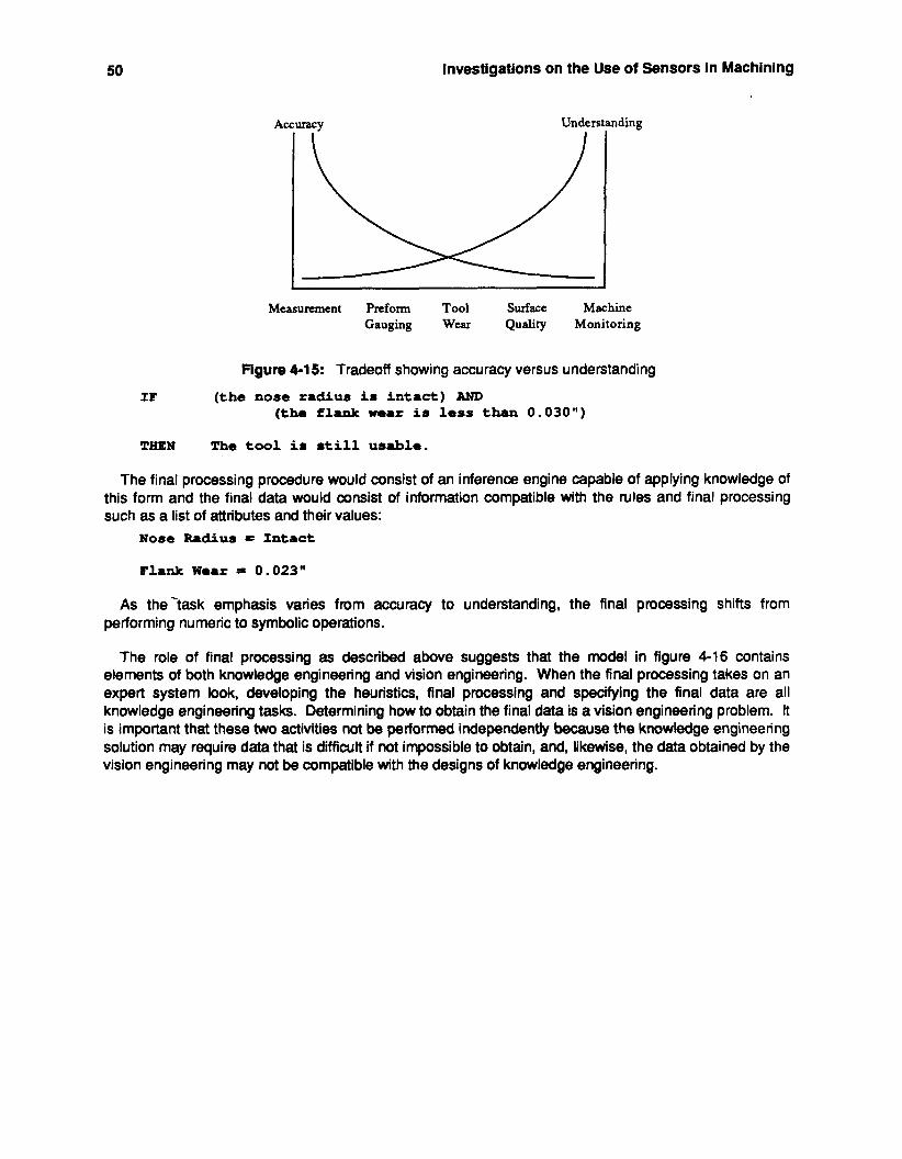
50 Investigations on the Use of Sensors In Machining
mding
Surface Machine Measurement Preform Tool Gauging Wear Quality Monitoring
Flgure 4-15: Tradeoff showing accuracy versus understanding
I F ( t h e nose radius is i n t a c t ) AND (the flank w e a r i s less than 0.03011)
THEN T h e tool is 8till us8ble.
The final processing procedure would consist of an inference engine capable of applying knowledge of this form and the final data would consist of information compatible with the rules and final processing such as a list of attributes and their values:
Nose Radius = Intact
Flank Wear = 0.023"
As the-task emphasis varies from accuracy to understanding, the final processing shifts from performing numeric to symbolic operations.
The role of final processing as described above suggests that the model in figure 4-16 contains elements of both knowledge engineering and vision engineering. When the final processing takes on an expert system look, developing the heuristics, final processing and specifying the final data are all knowledge engineering tasks. Determining how to obtain the final data is a vision engineering problem. R is important that these two activities not be performed independently because the knowledge engineering solution may require data that is difficult if not impossible to obtain, and, likewise, the data obtained by the vision engineering may not be compatible with the designs of knowledge engineering.
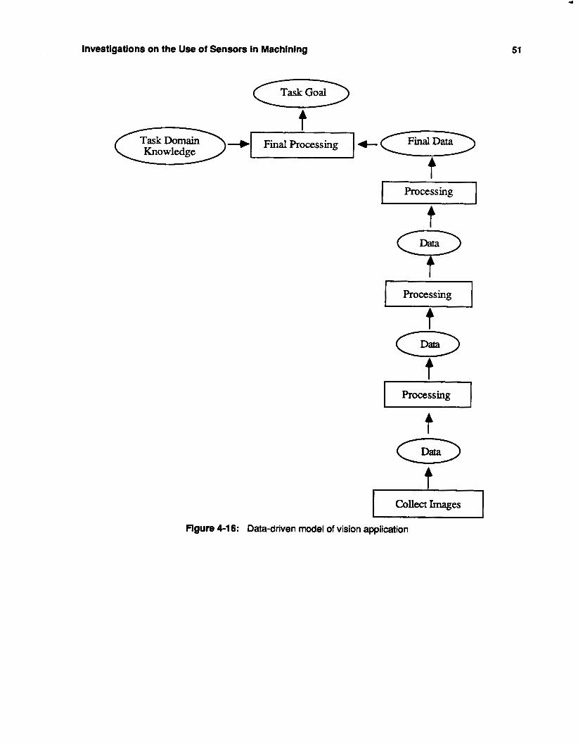
*
Investigations on the Use of Sensors In Machinlng
Task Goal
4
51
t
Collect Images
Figure 4-1 6: Data-driven model of vision application
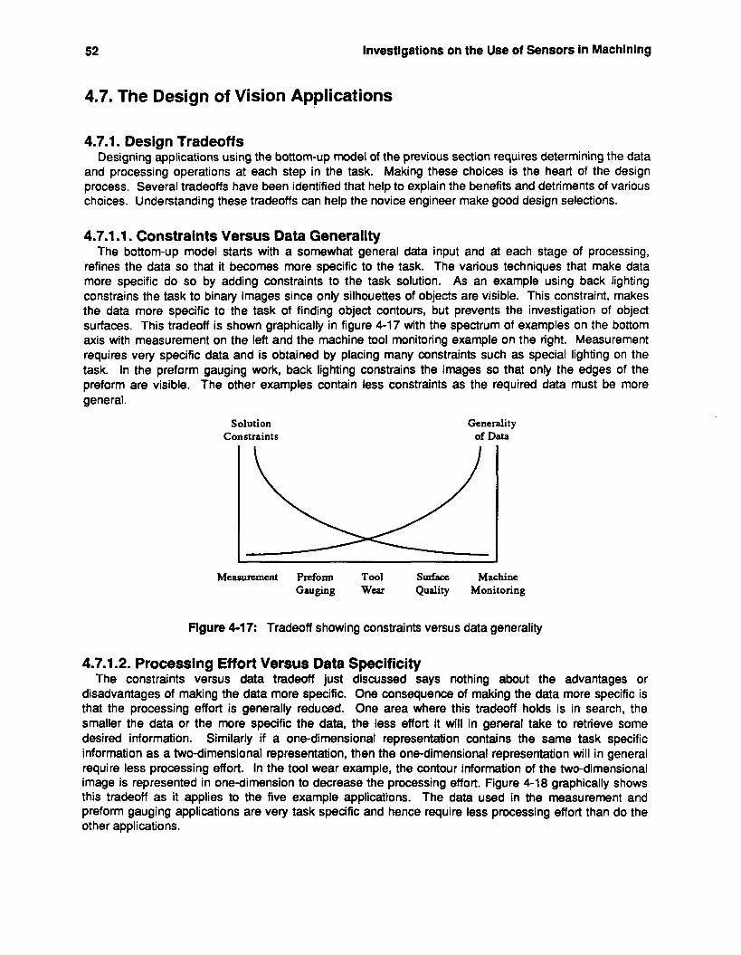
52 Investigations on the Use of Sensors in Machining
4.7. The Design of Vision Applications
4.7.1. Design Tradeoff s Designing applications using the bottom-up model of the previous section requires determining the data
and processing operations at each step in the task. Making these choices is the heart of the design process. Several tradeoffs have been identified that help to explain the benefits and detriments of various choices. Understanding these tradeoffs can help the novice engineer make good design selections.
4.7.1.1. Constraints Versus Data Generality The bottom-up model starts with a somewhat general data input and at each stage of processing,
refines the data so that it becomes more specific to the task. The various techniques that make data more specific do so by adding constraints to the task solution. As an example using back lighting constrains the task to binary images since only silhouettes of objects are visible. This constraint, makes the data more specific to the task of finding object contours, but prevents the investigation of object surfaces. This tradeoff is shown graphically in figure 4-17 with the spectrum of examples on the bottom axis with measurement on the left and the machine tool monitoring example on the right. Measurement requires very specific data and is obtained by placing many constraints such as special lighting on the task. In the preform gauging work, back lighting constrains the images so that only the edges of the preform are visible. The other examples contain less constraints as the required data must be more general.
Solution Constraints
Generality of Data
Measurement Preform Tool Surface Machine Gauging Wear Quality Monitoring
Figure 4-17: Tradeoff showing constraints versus data generality
4.7.1.2. Processing Effort Versus Data Specificity The constraints versus data tradeoff just discussed says nothing about the advantages or
disadvantages of making the data more specific. One consequence of making the data more specific is that the processing effort is generally reduced. One area where this tradeoff holds is in search, the smaller the data or the more specific the data, the less effort it will in general take to retrieve some desired information. Similarly if a one-dimensional representation contains the same task specific information as a two-dimensional representation, then the one-dimensional representation will in general require less processing effort. In the tool wear example, the contour information of the two-dimensional image is represented in onedimension to decrease the processing effort. Figure 4-18 graphically shows this tradeoff as it applies to the five example applications. The data used in the measurement and preform gauging applications are very task specific and hence require less processing effort than do the other applications.
. . Investigations on the Use of Sensors in Machining 53
. . Specificity Processing
of Dafa Effort
Measurement Preform Tool Surface Machine Gauging Wear Quality Monitoring
Figure 4-18: Tradeoff showing processing effort versus data specificity
4.7.1.3. Flexibility versus Data Specificity The effort versus data tradeoff suggests that making the data more specific is desireable as it reduces
the processing effort. However, there is a price to pay for this reduction in processing. Figure 4-19 shows that as the data becomes more specific, the task flexibility decreases. In the preform gauging example the use of back lighting makes the image data more specific and less processing effort is necessary to locate the edges. However, this choice reduces the flexibility, because less information is available-in particular, concave objects cannot be inspected because surface information is not present. The machine tool monitoring system must be able to understand a wide variety of images (i.e. high flexibility) and thus requires very general data.
specificity of Data
Solution Flexibility
Measurement Preform Tool Surface Machine Gauging Wear Quality Monitoring
Figure 4-19: Tradeoff showing flexibility versus data specificity
4.7.2. Sufficient Data and Processing Ability The design of a bottom-up vision application requires that the engineer determine the data and
processing operations at each step. Two important questions that the vision engineer asks at each step are concerned with the choice of data and processing:
1. Is the data suffiaent to solve this part of the task?
2. Can the data be processed efficiently?
The tradeoffs of the previous section indicate that constraining the task causes the data to become more specific. This can create a problem as the data may become so specific that it no longer contains
54 Investigations on the Use of Sensors in Machining
sufficient information. This is very true of scene selection. If the original series of images do not contain sufficient information, the task cannot be solved. In the measurement example, the distance between two holes is to be determined, if the input image contains only one of them, then the task cannot be performed.
Consider an application where an edge detection operation is to be followed by one that extracts line segments. One image output by the edge detector has good pixel connectivity while another has a few gaps in the connectivity. A human observer will fill in the gaps in the second image to form subjective contours (Marr 1982) and it may thus appear that both images have the same information. However, because the second image lacks good connectivity, the processing operation that worked satisfactorily on the first image may not work on the second. A different processing operation, less efficient than the first approach, that incorportes subjective contours may have to be applied.
4.7.3. Plan Generation A vision application can be viewed as a plan specifying the processing operations to apply, the data to
be processed, and the order in which the processing is to occur. Generating a bottom-up plan can be performed as a "top-down" or "goal-directed" search. The search space can be represented as a Vision plan tree" where nodes in the tree are data and links connecting the nodes are processing operations. A plan is a path in the tree that starts with the task goal and ends with taking a picture or group of pictures. A partial vision plan tree for the preform gauging example is shown in figure 4-20. The root node of the tree is the task goal, in this case cross-sectional measurements. Processing operations that result in the data at a node are added to that node and in this case are operations that result in the desired measurements. For now, assume that one such operation exists--cross-section feature extraction--and that it requires a list of cross-section contour points as input. The input of a processing operation associated with a link is added as a node at the end of that link. This process continues until the terminal nodes are image acquisition operations. The resulting tree can be searched using a number of techniquegsuch a depth-first or breadth-first, for a suitable path.
Once a vision tree has been constructed all possible vision plans can be generated. Many of these plans are not feasible for one reason or another, such as requiring data which cannot be obtained. However many of the plans are feasible and the vision engineer must choose a path which best solves the given task. A path is generated by starting at the top node of the tree and following links to successive nodes. At each node several links might be possible, representing the different choices in processing operations. For example in figure 4-20, the edge data required for the reconstruction, can be obtained by back lighting or front lighting. Each choice has advantages and disadvantages that can be considered to obtain the best choice. The tradeoffs presented previously can be used to help make the choices and understand their consequences. Also, for each choice, the questions of sufficient data and the ability to process it can be asked to insure the path is feasible.
4.8. Design Paradigm Applied to an Autonomous System The generation of vision plans described so far is open loop, with no feedback concerning the quality or
the feasibility of the generated plan. For example a plan might be generated that calls for segmentation using a single threshold and front lighting. This requires that the light be adjusted so the gray level image is composed primarily of two colors, one being object and the other background. If such an image is obtained, then a threshold can be computed from the gray level histogram. Vision engineers determine if a portion of a vision plan is acceptable by actually trying it out and observing the results. In this case after thresholding the input image, the engineer can look at the resulting binary image to see if it meets his expectations. In an autonomous system, no human is available to insure that a processing operation has produced an expected output. However, the vision plan does include a specification of the data at each step in the plan. Continuing with the example, the success of the thresholding could be determined by an
Investigations on the Use of Sensors in Machining 55
1 Cross- Section
Feature Extraction
Reconstruct From Reconstruct From Many Edge Segments Many 2 1/2 D Depths
Back Front Light
I I I
Images
Figure 4-20: Vision plan tree for the preform gauging example
evaluation function that measured some simple features of the resulting image based on expectations. For example the thresholding operation might be followed by a connectivity operation that groups connected pixels together into regions, called "blobs", and forms a "blob-tree" that describes the relationship of blobs to each other. When the plan is generated, an expected range in the number of blobs can be included as part of the data describing the output of the connectivity operation, which is directly affected by the success of the thresholding. If the connectivity operation does not produce the expected output, it is because some previous aspect of the plan has failed, such as the thresholding. Evaluation functions can also be associated with the input of operations. For the thresholding operation, the histogram of the input image can be examined to determine if the resulting illumination and camera setup has produced a suitable bimodal image.
56 investigations on the Use of Sensors in Machining
Using evaluation functions, allows the bottom-up approach to incorporate some feedback as to the performance of the current plan. At each step in the plan where an evaluation function exists, the success of the plan executed thus far can be measured. If a problem is detected, that portion of the plan executed so far, can be replanned as a sub-task using the current data as the task goal. For example, if the blob-tree resulting from a connectivity operation does not meet expectations, then a different form of thresholding should be tried. This sort of vision processing scheme incorporates elements of both goal- driven and data-driven processing. The initial task goal is used as the input to generate a plan in a goal-driven fashion. The resulting plan is executed in a data-driven fashion. If, during the execution, the plan is found to be incorrect, then that portion of the task can be replanned using the goal-driven approach.
4.9. References Brodmann, R., Thurn, G. and Gast, Th. 1984. An Optical instrument for Measuring the Surface
Roughness in Production Control, in CIRP, Vol. 33, No. 1, pp. 403-406.
Cutkosky, M. R., and Wright, P. K. 1986. Active Control of a Compliant Wrist in Manufacturing Tasks, Transactions of the ASME, Journal of Engineering for Industry, Vol. 108, pp.36-43.
Daneshmend, LK. and Pak, H.A. 1983. Performance Monitoring of a Computer Numerically Controlled Lathe Using Pattern Recognition Techniques, in SPiE’s Third lntemational Conference on Robot Vision and Sensory Controls, pp. 31 2-322.
Englert, P. E., and Wright, P. K 1986. Applications of Artificial Intelligence and the Design of Fixtures for Automated Manufacturing, Proceedings of the IEEE Conference on Robotics and Automation, San Franscisco, pp. 346-351.
._ Giusti, F. and Santochi, M. 1979. Development of a Fibre Optic Sensor for In Process Measurement
of Tool Flank Wear, in Proceedings of the 20th lntemational Machine Tool Design and Research Conference, pp. 351 -360.
Goldstein, M., Wrlght, P. and Bourne, D. 1985. A Fast Algorithm for High Accuracy Gauging Using Computer Vision, in Robotics and Computer Integrated Manufacturing, Vol. 2, No. 2, pp. 105-1 13.
Haralick, R. 1979. Statistical and Structural Approaches to Texture, in Proceedings of the IEEE, Vol. 67, NO. 5, pp. 786-804.
Haralick, R., Shanmugam, K. and Dinstein, 1. 1973. Textural Features for Image Classification, in lEEE Transactions on System, Man, and Cybernetics, Vol. SMC-3, No. 6, pp. 61 0-621.
Marr, D. 1982. vision, W.H. Freeman Co., NY.
Takeyama, H., Dol, Y., Mftsuoka, T. and Seklguchi, H. 1967. Sensors of Tool Life for Optimization of Machining, in Proceedings of the 8th lntemational Machine Tool Design and Research Conference, pp. 191 -208.
Takeyama, H., Sekiguchl, H. and Murata, R. 1976. In-Process Detection of Surface Roughness in
Wright, P. K., and Bourne, D. A. 1988. Manufacturing Intelligence, Addison-Wesley Publishing Co.,
Machining, in CIRP, Vol. 25, No. 1, pp. 467-471.
Reading, MA.
Workholding: Qualitative and Quantitative Planning 57
5. Workholding: Qualitative and Quantitative Planning An intelligent selection of clamps, jigs, and fixtures, and values for part production process variables,
can be made using a mix of qualitative and quantitative methods. To demonstrate this idea, a control framework is proposed in which guidelines obtained from human experts and information derived from basic first order physics-based models are complemented and reinforced by empirical or handbook data and numerical approximation programs. This chapter will focus on the qualitative aspects of the control loop. The purpose of this effort is to construct a planner which achieves “first part right” production, and can be used to aid in the design and control of future workholding devices.
5.1. Workholding: Managing Qualitative and Quantitative Knowledge Knowledge accumulated from human experts and the analytical approximations of part machining
operations is vital for the creation and continued growth of an automated planning system. However, this raw data alone does not constitute a complete and coherent system. The data must be logically categorized within some framework that is conducive for machine process planning. At the core of any expert system there must lie a control structure, however loose it may be, to moderate the flow of rules and data necessary to generate successive planning steps. This algorithm must be used to scan data and rule bases in search of pieces of information relevant to the part to be machined. A proposed control structure that incorporates both qualitative and quantitative information for the planning of machined parts is shown in Figure 5 1 .
The qualitative branch of the system is comprised of modules that each perform specific tasks. A Feature Selection Module contains guides that help to order the sequence of cuts to be made to the workpiece. The Clamp Selection Module chooses from the CAD database, of clamp and fixture units, the appropriate workholding components for a particular machining process step. The Clamp Placement Module proposes clamp configurations about the workpiece, and workpiece positions on fixture locators.
- Each module of the qualitative branch proposes an action to be taken and acts as a critic of actions
proposed by the other modules. Actions might include, for example, a clamp selection, the input of a feature, or the changing of a clamp position. Proposed module actions are made based on each one’s own set of guides. The guides may be manifested in various forms; recommended machining and clamping actions, tradeoffs between variables relevant to a planning step, or expert numerical approximations of safe parameter values or ranges.
The module guides have been placed into one of three priority levels; the necessary Level I guides take precedence over the preferred Level II guides, which in turn take precedence over the efficiency oriented Level ill guides. This ordering does not imply that Level I11 guides are unimportant or to be bypassed in most situations. The guideline hierarchy is established to resolve conflicts among competing courses of action as they may arise during planning. These conflicting courses of action might involve, for example, the choice of one type of clamp over another or the decision to machine one feature before another. After a course of action has been decided upon, its competitors are not discarded, but rather are stored in a prioritized list for possible future use. For instance, if it is later determined that a certain clamp type is inappropriate for the machining parameters chosen, then an alternative type of clamp is selected from the module’s priority list. in cases where module guides at equivalent levels are in conflict (e.g. a Level II feature guide versus a Level II clamp placement guide), then decsions are made in favor of actions that should maintain specified machining accuracies. If it is deemed that both the competing actions should lead to similar accuracies, then a decision is made in favor of actions that will keep the overall production rate high. The details of Level I through Level ill guidelines for Feature Selection, Clamp Selection, and Clamp and Part Placement are discussed in the following sections.
The quantitative branch of the planning system also consists of distinct modules that perform specific duties. A Computer Aided Design (CAD) module describes workpiece features, cutting tools, clamps, and
58 Workholding: Qualitative and Quantitative Planning
KNOWLEDGE-BASED, QUALITATIVE GUIDELINES
ANALYTICAL-B ASED, QUANTITATIVE INFORMATION
KEY
I I I-[ EXCHANGE OF QUALITAlWE INFORMATION
I EXCHANGE OF INFoRMAnON BEIWEEN 1-m QUAUTAlWE & QUAN"ATIVE BRANCHES I - - - - -, FLAWED PARTPRODUCTION STATE
Figure 5-1 : Control Structure for Part Process Planning System
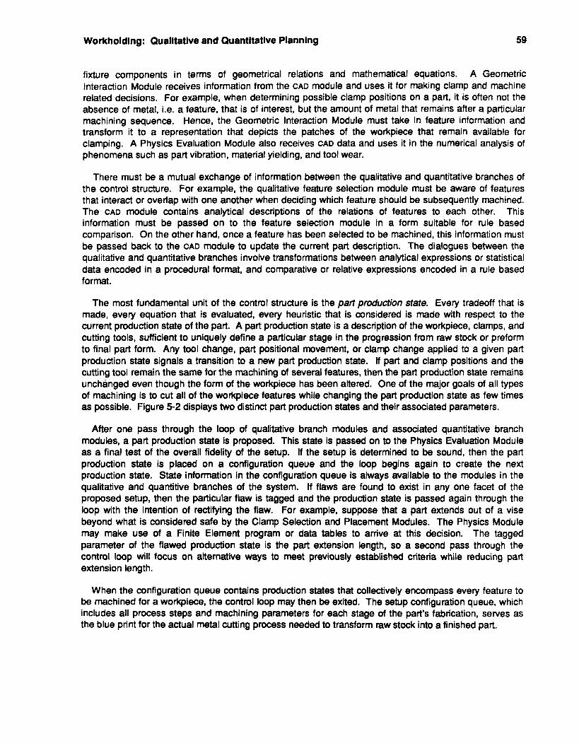
Workholding: Qualitative and Quantitative Planning 59
fixture components in terms of geometrical relations and mathematical equations. A Geometric Interaction Module receives information from the CAD module and uses it for making clamp and machine related decisions. For example, when determining possible clamp positions on a part, it is often not the absence of metal, i.e. a feature, that is of interest, but the amount of metal that remains after a particular machining sequence. Hence, the Geometric Interaction Module must take in feature information and transform it to a representation that depicts the patches of the workpiece that remain available for clamping. A Physics Evaluation Module also receives CAD data and uses it in the numerical analysis of phenomena such as part vibration, material yielding, and tool wear.
There must be a mutual exchange of information between the qualitative and quantitative branches of the control structure. For example, the qualitative feature selection module must be aware of features that interact or overlap with one another when deciding which feature should be subsequently machined. The CAD module contains analytical descriptions of the relations of features to each other. This information must be passed on to the feature selection module in a form suitable for rule based comparison. On the other hand, once a feature has been selected to be machined, this information must be passed back to the CAD module to update the current part description. The dialogues between the qualitative and quantitative branches involve transformations between analytical expressions or statistical data encoded in a procedural format, and comparative or relative expressions encoded in a rule based format.
The most fundamental unit of the control structure is the part production state. Every tradeoff that is made, every equation that is evaluated, every heuristic that is considered is made with respect to the current production state of the part. A part production state is a description of the workpiece, clamps, and cutting tools, sufficient to uniquely define a particular stage in the progression from raw stock or preform to final part form. Any tool change, part positional movement, or clamp change applied to a given part production state signals a transition to a new part production state. if part and clamp positions and the cutting tool remain the same for the machining of several features, then the part production state remains unchanged even though the form of the workpiece has been altered. One of the major goals of all types of machining is to cut all of the workpiece features while changing the part production state as few times as possible. Figure 5 2 displays two distinct part production states and their associated parameters.
After one pass through the loop of qualitative branch modules and associated quantitative branch modules, a part production state is proposed. This state is passed on to the Physics Evaluation Module as a final test of the overall fidelity of the setup. If the setup is determined to be sound, then the part production state is placed on a configuration queue and the loop begins again to create the next production state. State information in the configuration queue is always available to the modules in the qualitative and quantitive branches of the system. If flaws are found to exist in any one facet of the proposed setup, then the particular flaw is tagged and the production state is passed again through the loop with the intention of rectifying the flaw. For example, suppose that a part extends out of a vise beyond what is considered safe by the Clamp Selection and Placement Modules. The Physics Module may make use of a Finite Element program or data tables to arrive at this decision. The tagged parameter of the flawed production state is the part extension length, so a second pass through the control loop will focus on alternative ways to meet previously established criteria while reducing part extension length.
When the configuration queue contains production states that collectively encompass every feature to be machined for a workpiece, the control loop may then be exited. The setup configuration queue, which includes all process steps and machining parameters for each stage of the part's fabrication, serves as the blue print for the actual metal cutting process needed to transform raw stock into a finished part.
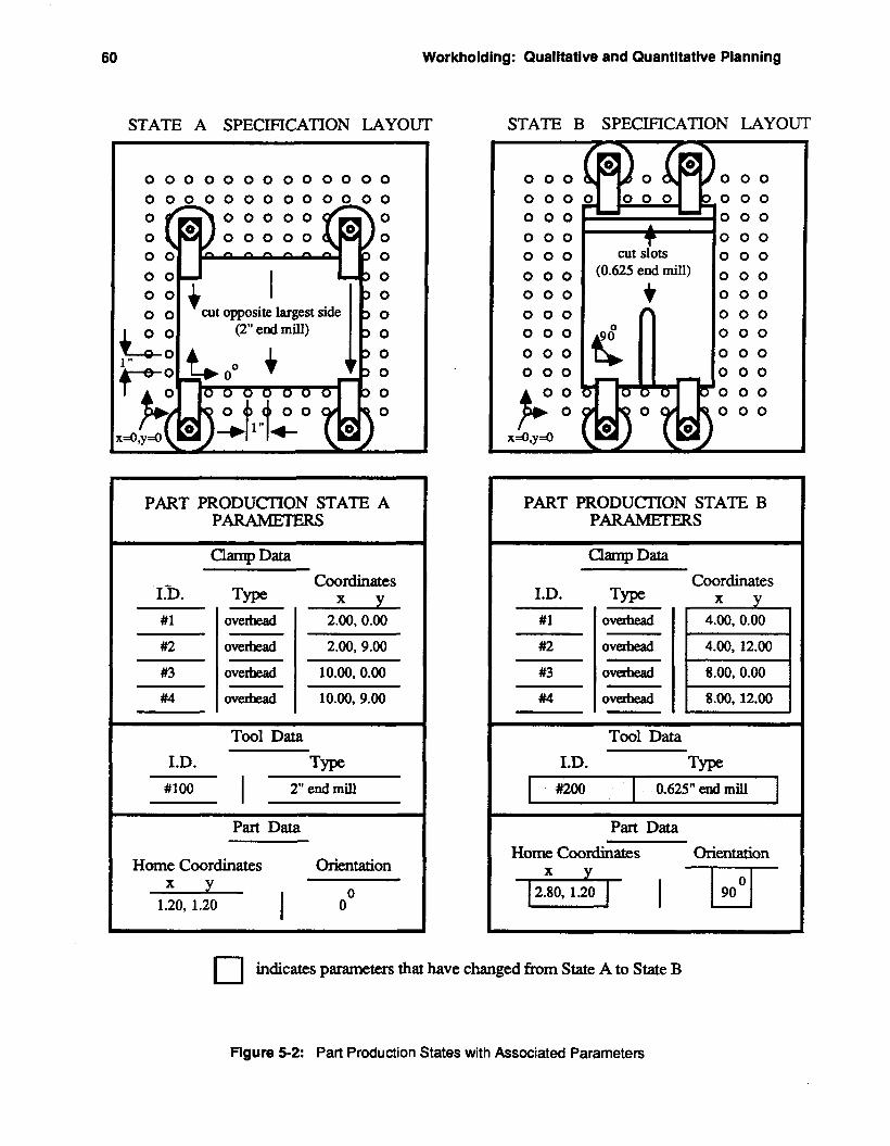
60 Workholding: Qualitative and Quantltatlve Planning
#1
#2
#3
#4
STATE A SPECIFICATION LAYOUT
ovehead 2.00, 0.00
wehead 2.00, 9.00
o v e M 10.00, 0.00
overhead 10.00. 9.00
0 0 0 0 0 0 0 0 0 0 0 0 0
PART PRODUCIION STATE A PARAMETERS
Tool Data
I.D. Type
Part Data
Home Coordinates Orientation
~
X Y 1.20, 1.20 I O0
STATE B SPECIFICATION LAYOUT
0 0 0 0
PART PRODUCTION STATE B PARAMmERS
~
Clamp Data Coordinates
I.D. Type #1
#2 4.00, 12.00 I I C I
Tool Data
I.D. Type a00 0.625" end mill 1
~~ ~~
Part Data Home Coordinates Orientation
indicates parameters that have changed h m State A to State B
Figure 5-2: Part Production States with Associated Parameters
Workholdlng: Qualitative and Quantltative Planning 61
5.1.1. Qualitative branch of control loop The qualitative branch of the control loop consists of three modules; Feature Selection, Clamp
Selection, and Clamp and Part Placement. Each module consists of levels of guidelines and a prioritized listing of actions to be taken. The specifics of the guidelines are herein discussed.
5.1.1 .l. Feature selection module
feature machining efficiency guides. There are three levels of Feature Selection guides: global feature guides, local feature guides, and
At the top tier of the feature selection module are the Level I guides, illustrated in condensed form in Table 5-1. These may be thought of as global feature guides because they apply to all features to be machined into a workpiece. Failure to adhere to these principles usually leads to part scrap or rework, no matter how well Level II or 111 guides are executed.
The first guide deals with the relation between dimensional tolerances and planning and production difficulty. More stringent tolerances require increased care in the setup of a part. This increased care may mean additional steps to cool the workpiece between machining operations (especially in the case of large cuts made into some grades of aluminum) so that it may reach an equilibrium state. If considerable warping or thermal expansion has occurred, the workpiece may need to be compressed (e.g. in an arbor press) to a desirable form for subsequent machining steps. Also, extra or more detailed gaging steps may be necessary to ensure that tolerances are being met.
For any part or feature surface, it is important to select the proper machining process and tooling to meet stated surface finish requirements. As expected, finer surface finishes require more expensive and more time consuming operations. A 125 p inch finish is a common specification for many job shop parts.
It is imperative to select the proper tool to machine a feature. Some features may be machined with several different types of tools; others require uniquely designed cutter shapes. Attempts to machine features with inappropriate tools often result in part scrap, tool breakage, or both. The tooling sequence to produce a single feature is also critical, e.g. tap holes before taps, or straight slots before dovetail or T-slots.
Before any features are cut, it is important, in most cases, to produce accurately machined surfaces to locate from. In the case of prismatic parts, this means that three, good quality, orthogonal surfaces should be present on the workpiece before feature addition. When dimensional tolerances are more liberal, e.g. looser than 0.005 inch, rolled surfaces may suffice as appropriate locating surfaces. When tolerances are tight, e.g. finer than 0.001 inch, then it is necessary to produce three, orthogonal, machined sides before feature addition. In no case should saw cut surfaces be used for feature datu mi ng .
A brief sampling of some prominent Level I I feature guides is shown in Table 5-2. Unlike each Level I guide that globally applies to all features to be machined, each of the Level II guides is more directed to the successful completion of one specific feature or a small set of features and thus may be referred to as local feature guides. Consider the first Level I I guide that deals with the drilling of holes through curved and flat surfaces. If this guide is ignored and a hole is drilled through a wwed surface, the drill bit will tend to race along the surface and the accuracy of the hole produced may not meet specified requirements. However the accuracy of other features not yet cut may be independent of the imprecise hole through the curved surface. In some cases the part may be salvaged even though a particular feature is flawed (e.g. a Helicoil or plug may be inserted into a flawed hole and then redrilled or retapped). These Level II guides have been gleaned from expert craftsmen and machining handbooks and have been found to be reliable ways of avoiding disaster.
62
A.
b
Workholding: Qualitative and Quantitative Planning
As the tolerances for part dimensions become more stringent, more thorough planning is needed for sen and machining steps, and more carefully monitoring is required during clamping and metal cutting. The
-I x I- * 0.001
B .
0 to
It is important to select the proper machining process to attain the specified surface frnish for an entire part surface or a feature surface. Typical operations required to obtain ranges of surface finishes are given above: operations near the top of the list are the most expensive and time consuming.
Cooling of part between steps
C .
compensate for thermal expansion
It is extremely important to match the proper cutting tool with a feature to be machined. Counterbores, countersinks, large bores, taps, keyways, and T or dovetail slots are types of features needing special tools. Attemps to cut a feature without the proper tool ohen result in excessive time or tool breakage..
Very precise gaging of critical part dimensions
D. It is usually necessary to produce rhrrc orthogonal, machined part surfaces before proceeding with the
.subsequent steps of a part proccss plan. AU features must be accurately located with respect to each of these three, accurately machined part surfaces.
c
Workholding: Qualitative and Quantitative Planning
A.
63
When a hole must be drilled through a cylindrical surface, if possible, any flat surfaces that coincide with the hole should be machined prior to the hole. This is so that the drill will be perpendicular to the cuttine ana and thus drill racing and the chance of tool breakage will be reduced.
6) preferred
B.
over
When through holes open onto other features such as the shoulder shown above, it is recommended to drill the hole before milling the shoulder. Through holes must be carefully placed with respect to other part sections or else interference and tool breakage may occur.
c.
-b
Avoid situations where a milling cutter must be simaltancously in contact with two orthogonal surfaces. For example, great stresses will be induced in the above end mill if it contacts both adjacent diameters. Any features between two orthogonal surfaces (such as the chamfer shown above) should be cut first.
preferred
D.
over
When a hole diameter is much less than the diameter of the stock and passes through the entire length oj the stock, AND a slot must also be machined as shown, it is proper to machine the slot before the hole. Less material will have to be removed for the hole and thus less stress will be exerted on the drill.
-b
over
preferred over
64 Workholding: Qualitative and Quantitative Planning
A listing of some common Level Ill feature guides is given in Table 5-3. Level Ill feature guides focus mainly on methods to alleviate cutting path complexity and to reduce tool and clamp changing time, and thus they are called feature machining efficiency guides. While it is important to follow these rules of thumb for improving efficiency, they may only be considered after all applicable Level I and II guides have been satisfied. For example, suppose a certain workpiece surface requires two pockets of equal size to be milled through it, but an opposite surface requires a hole to be drilled through it that overlaps with an edge of one of the pockets, Figure 5-3. The Level Ill, Guide D calls for pockets of equal radii to be done in successive steps, however doing so for the described part would make it difficult to drill a hole through an edge of a pocket, a clear violation of the Level 11, Guide B. Hence, the appropriate course of action would be as follows: mill one pocket, make a tool change to a drill and drill the hole, and finally, make a tool change and mill the other pocket. In this case, savings in tool changing and gaging time must be sacrificed at the expense of achieving machining accuracy.
The outcome of the Feature Selection Module is a proposed list of features to be machined, given other information on the current state of a part, e.g. clamp positions, tooling considerations, etc. This feature list is an important source of information necessary to help define a single part production state. This information is made available to the Clamp Selection and Clamp Placement Modules for further specification of the production state.
5.1.1.2. Clamp selection module The Clamp Selection and Placement Guide visual aids are comprised of several distinct types of charts
and diagrams. Some illustrations, such as those in Table 5-4, convey methods of avoiding common clamping difficulties and are mostly self explanatow. Bar graphs, such as the one at the top of the right hand column for Guide 0, depict approximations obtained from epxefls in terms of discrete increments of the parameters involved. For some events such as buckling or vibration, it is easier for a human to convey his knowledge in terms of discrete increments in mrkpiece dimensions, rather than the monotonic curves m m o n in physics based analyses. Some tradeoff diagrams, such as the one at the top of the right hand column of Guide C, have two attributes listed on vertical axes that are both functions of another attribute listed on a horizontal axis. The axes in these diagrams have units (e.g. pounds) to scale the attributes, and the unit values are either derived from simple physical models or approximate quantitative data obtained from human experts. Another guide diagram used is also a tradeoff chart, but rather than numerical units, its axes have qua1itaWe levels (e.g. high, low) that help to visualize trends for some variables that are diffiwlt to obtain data for model building.
Table 5-4 illustrates some examples of the clamp selection guide that must always be obeyed; the workpiece must be able to fit within the working envelope of a clamping device or fixture table. This Level 1 clamp selection guide may thus be cited as the clamp envelope selection guide. This guide may seem somewhat trivial, but in fact it is useless to begin to consider clamgpart interactions or complex tradeoffs if the workpiece to be machined is larger than the greatest possible opening of the workholding device or if it extends beyond the confines of the fixture or machine tool bed.
There is a clear division between the Level I and I I clamp selection guides. Level II guides may, in certain circumstances, be only partially satisfied while the Level I clamp envelope guide must always be completely satisfied. Each Level II clamp selection guide has some central theme, and contains expert approximations or tradeoff charts to help choose a suitable clamp. Because the Level II guides cover a variety of clamping problems that may affect the success or failure of a machining operation, they may be referred to as problem specific clamp selection guides.
The first Level II guide relates directly to the metal to be removed from a workpiece. As the volume of metal removed from the raw stock increases, the part’s resistance to bending or buckling induced by clamping or cutting forces decreases. Often, when an expert machinist is presented with the engineering drawing or isometric sketch for a part, his initial assessment of the degree of difficulty for machining it is
Workholding: Qualitative and Quantitatlve Planning 65
A.
preferred over I
Whenever feasible, features should be machined in such an order that the need for tool changes is kept to a small number. A decrease in the tool changing time will be accompanied by an increase in part production rate.
c.
then
Because fixture tables, vises, and most other clamps have flat surfaces, it is often desircd to reserve the cutting of ~ g l e d surfaces for the latter stages of part production. This may reduce the number of part
It is preferred to cut Ptojections above a part face when hey are the same bcight above the surface of the face. This is to ease proLpmming and to reduce overall machining time.
It is desired to plan the cutting of pockets such that ones with qual radii arc done during the same or successive steps.. This will reduce the number of tool changes required for the operation. I ..I
~ ~~~~ ~
Table 5-3: Level 111 Feature Selection Guides, Feature Machining Efficiency Guides
66 Workholding: Qualltative and Quantitative Planning
~ ~~~
Not Preferred
Level III, Guide D precedence o w Level II. Guide B - Results in drill interference with pocket edge
Preferred
Level II, Guide B precedence over Level III, Guide D - No drill interference with pocket edge
I Y m
Figure 5-3: Example of a Level ll feature guide precedence over a Level Ill feature guide
strongly coupled to the quantity of metal to be removed from the stock cross section. The expert is not only considering the total amount of metal removed, but rather the form of the metal remaining after machining. Slender ribs, thin,walled cross sections, and long, narrow part members are prominent indicators of possible fixturing difficulties because of increased part susceptibility to buckling, bending, and yielding produced by forces that exist during common cutting and clamping operating conditions. It follows therefore, that a description of the workpiece in terms of the metal that remains after machining features in addition to a description of the features themselves would be useful for determining a suitable clamp for the workpiece. A method for transforming a feature description of a part to a description in terms of solid members and available clamp surfaces is necessary. Table 5-5, Level II, Guide A shows how a part to be machined from prismatic stock may be described in terms of solid members. Expert machinists were presented a drawing for this part and queried about how it would be clamped. Because little metal remains from the original stock, the latter stages of machining become quite difficult and it was agreed that a specially designed fixture would be required to grip the part. In fact, the part was redesigned, Figure 5-4, to make it possible to easily clamp it either in a vise or with toe clamps.
A strong indicator of the difficulty of holding a part with standard clamps, e.g. a vise or toe clamps, is the total area of pairs of part surfaces with solid metal connections between them, adjoining the bounding part envelope. If this total area is small (less than 10% of the original bounding envelope area) then most likely special fixtures will be needed to hold the part. It is important to note that the configuration of the part block members is as important as the quantitative amount of metal removed when determining the degree of difficulty of clamping. A steel block that is to have several large bores machined through it may
Workholding: Qualitative and Quantitative Planning 67
Part clamped in a 3 jaw chuck Part unable to be clamped in a 3 jaw chuck because of size restrictions of chuck
Part unable to be clamped in a standard vise because of size restrictions of vise Part clamped in a standard machine tool vise
I part clamped with toe clamps to a
standard machine tool bed Part unable to be clamped with toe clamps
because of size restrictions of tool bed
Table 59: Level I Clamp Selection Guide, Clamp Envelope Selection Guide

68 Workholding: Qualitative and Quantitative Planning
be easily clamped in a vise even though the percentage of metal removed is the same as the part in Figure 5-5.
Level 11, Guide B brings attention to another qualitative barometer of part-clamp stability. Without doing detailed statics or stress analyses, a human expert is quickly able to detect clamping situations that are potentially unstable or are in a narrow stability range. Cylindrical parts are best clamped in concentric grip devices (e.g. a chuck), angled contacts should be avoided, and all clamp and support forces should directly oppose each other. In some cases, these guides may be violated if machining forces are kept low. An example of this is the common practice of drilling small holes through a cylindrical part clamped in a vise. If a vise has been setup on a machine tool for other work related to the part, it is often practical to use it for light clamping of nonprismatic parts.
Level II, Guide C centers on clamp bending problems that may occur. Although all types of workholding devices experience some degree of bending during their operation, the vise is chosen as a model because of its simplicity. The applied vise clamping force must be chosen to provide enough resistance to machining forces yet maintain the unbent state of the part. If toe clamps are used, the part will not bend upward as in the vise, but the setup time for toe clamps is roughly fives times as long as with a vise.
Level II, Guide D addresses the possibility of part buckling in clamps. The experts’ approximations of part dimensions that increase the likelihood of buckling for a commonly applied clamping load are given in the bar chart. First order part-clamp friction and buckling models and estimates of relative setup times underscore the tradeoffs shown.
Level II, Guide E focuses on part vibration in clamps. The bar graph depicts the experts’ purported part dimensional ratios thought to be at the limits of vibration free operation under commonly used speed and feed rates. An approximate vibration model was used to generate the maintenance of nonvibrating part- production7ate tradeoff.
Level 11, Guide F shows the major points to be pondered when special purpose workholding devices such as magnetic and pneumatic tables are considered for use. Both provide complete accessibility to the top surfaces of a part and evenly distribute clamping loads over the entire part region thus virtually eliminating deformation problems. However the maximum holding forces of both pneumatic and magnetic tables are often considerably below that of toe clamps or vises, hence these devices are most often used for only light force applications such as grinding or light milling.
The Level Ill clamp selection guides suggest ways to make part production more efficient by reducing the amount of clamp changeover and increasing tool accessibility to the workpiece, and are thus termed clamping efficiency selection guides. These Level Ill guides are to be considered only after the Level I and II guides have been satisfied.
Guide A presents an example of the tradeoff that must be made when selecting clamps for stock that requires machining orthogonal sides. Retaining one type of clamp throughout the entire cutting operation will eliminate time needed for changeover to a new type of clamp, but may in some cases severely hinder accessibility to the part and therefore slow the rate of machining features. On the other hand, a changeover to a different type of clamp during intermediate machining steps may reduce the overall clamp setup rate, but may increase accessibility to the part and hence increase feature production rate. The bar chart helps to assess safe part heights above edge clamps when considering the factor of tipping moments induced by external cutting forces.
Workholding: Qualitative and Quantitative Planning 69
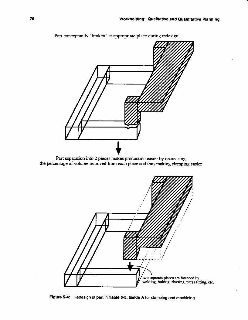
70 Workholding: Qualitative and Quantitative Planning
Part conceptually "broken" at appropriate place during redesign
Part separation into 2 pieces makes production easier by decreasing the percentage of volume removed from each piece and thus making clamping easier
Figure 5-4: Redesign of part in Table 5-5, Guide A for clamping and machining
ing, etc.
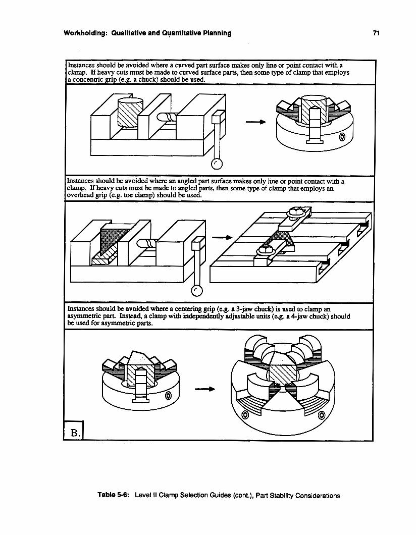
71 Workholdlng : Qualltative and Quantitative Planning
Instances should be avoided where a curved part surface makes only line or point contact with a clamp. If heavy cuts must be made to curved surface parts, then some type of clamp that employs a concentric grip (e.g. a chuck) should be used.
I Instances should be avoided where an angled part surface makes only line or point contact with a clamp. If heavy cuts must be made to angled parts, then some type of clamp that employs an overhead grip (e.g. toe clamp) should be used.
Table 5-6: Level II Clamp Selection Guides (ant.), Part Stability Considerations
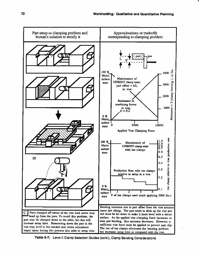
72 Workholding: Qualitative and Quantitative Planning
Part setup or clamping problem and human's solution to rectlfy it
.. Parts clamped off center of the vise lead screw may I b e n d up from the jaws. To avoid this problem, the 'art may be clamped down to the table, but this will icrease setup time. Hammering down the part in the ise may level it, but needed care (extra adjustment teps) taken during this process also adds to setup time.
Approximations or tradeoffs corresponding to clamping problem
loo %
unbent MainE
state
0 % MainL unbent
StatC
Loo %
unbent Main;
state
0 %
+- - + jaw
i- -7- - - - -
/ \
Maintenance of UNBENT clamp state;
part offset = h/L in vise
Resistance to machining forces
in vise;
1 I
5000
Applied Vise Clamping Force
~- Maintenance of - i UNBENT clamp state
with toe clamps
Production Rate with toe clamps relative to setup in a vise I I
. .-
Main 2 3 4
# of toe clamps used (each applying 5000 Ibs.) Sta te
100
1.0 0.9 0.8 0.7 0.6
0.5
0.4
0.3
0.2
0.1
3ending moments due to part offset from the vise actuato Lause jaw tilting. The part tends to slide up the vise jaw nd must be hit down to make it more level with a datum urface. As the applied vise clamping force increases so loes jaw bending, thus accuracy decreases. However, a ufficient vise force must be applied to prevent part slip. b e use of toe clamps eliminates the bending problem but increases setup time as compared with the vise.
Table 5-7: Level II Clamp Selection Guides (cont.), Clamp Bending Considerations
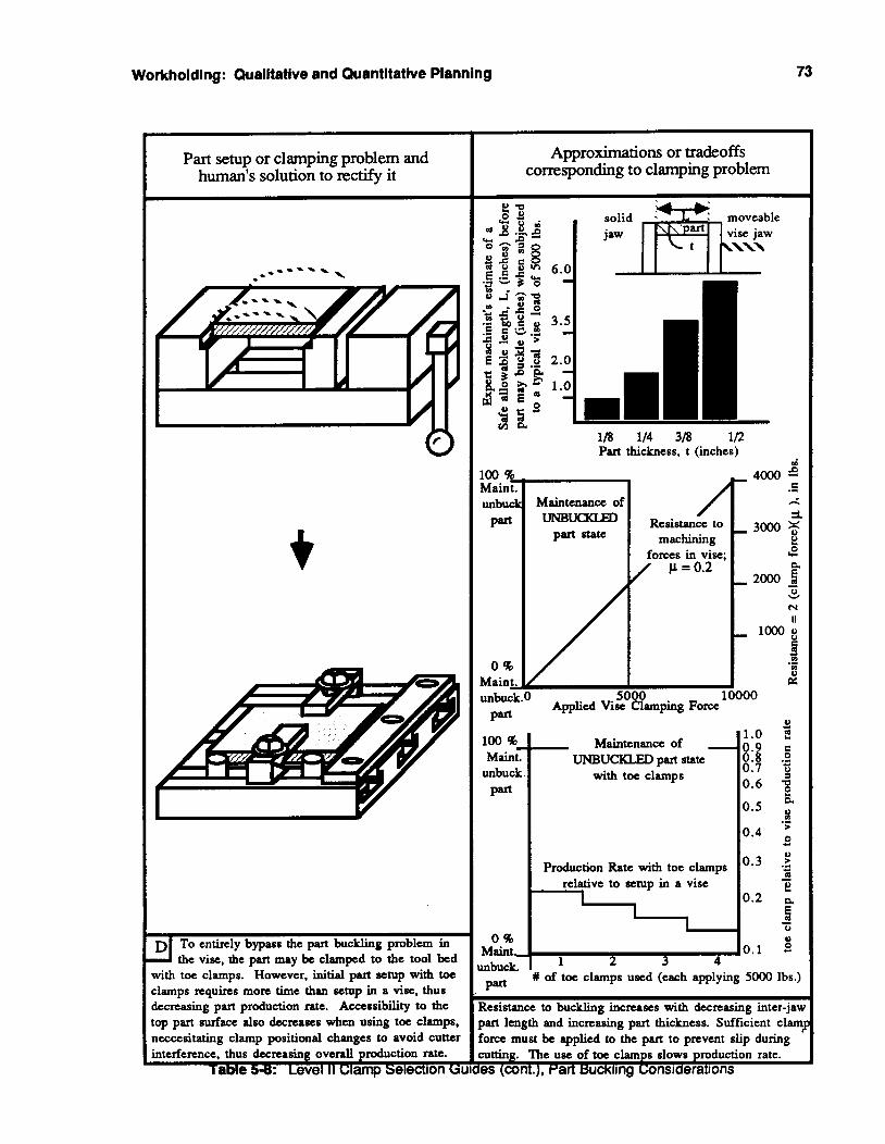
Workholding: Qualitative and Quantitative Planning 73
Maint. unbuck Maintenance of part UNBm
part state
Part setup or clamping problem and human's solution to rectifv it
C ." h
3. Resistance to 3000 5
machining 8 forces in vise; u? / p=0.2 P, - 2000
0
N II
v
- lo008 9 c) ." m 2
I
Production Rate with toe clamps relative to setup in a vise
1 I
I V 0.5
0.4
0.3
0.2
DI To entirely bypass the part buckling problem in the vise, the part may be clamped to the tool bed
with toe clamps. However, initial part setup with toe clamps requires more time than setup in a vise, thus decreasing part production ratc. Accessibility to the top part surface also decreases when using toe clamps, ncccesitating clamp positional changes to avoid cutter interference. thus decreasing overall production rate.
iaMe 5-8: Level II clamp Selection GL
Approximations or tradeoffs corresponding to clamping problem
118 114 318 1/2 Part thickness, t (inches)
Maintenance of
0.7 0.6
unbuck . with toe clamps
1 2 3 4 mbuck. I W of toe clamps used (each applying SO00 lbs.)
Part
Resistance to buckling increases with decreasing inter-$< part length and incre&g part thickness. Suffiiient clam.. Force must be applied to the part to prevent slip during :utting. "he use of toe clamps slows production rate. es (ant.), Part Buckling Considerations
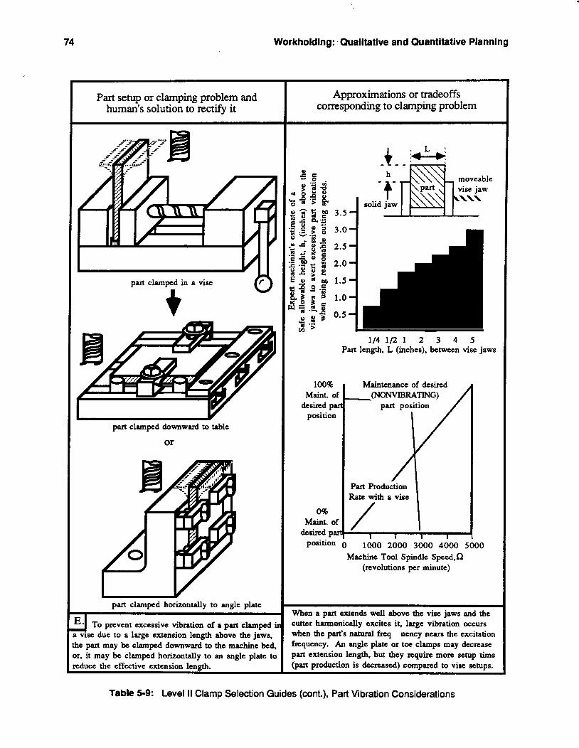
74 Workholding: Qualltative and Quantitative Planning
part clamped horizontally to angle plate r A To prevent excessive vibration of a part clamped i~ a vise due to a large extension length above the jaws, the part may be clamped downward to the machine bed, or, it may be clamped horizontally to an angle plate to reduce the effective extension length.
Part setup or clamping problem and human's solution to rectify it I
11/11
part clamped downward to table
or
Approximations or tradeoffs corresponding to clamping problem
100% Maint. of
position desired pal
0% Maint. of
desired pax
114 112 1 2 3 4 5 Part length, L (inches), between vise jaws
hfaintenance of desired
part position (NONVLBRATING)
Part Production Ratc with a vise / I
position 0 1000 2000 3000 4000 5000 Machine Tool Spindle Speed.Q
(revolutions per minute)
When a part extends well above the vise jaws and the cutter harmonically excites it, large vibration occurs when the part's natural f q uency nears the excitation frtquency. An angle plate or tot clamps may decrease part extension length, but they require more setup time (part production is decreased) compared to vise setups.
Table 5-9: Level II Clamp Selection Guides (cont.), Part Vibration Considerations
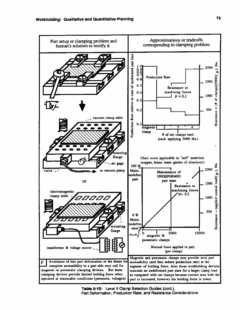
Workholding: Qualitative and Quantitative Planning 75
Part setup or clamping problem and human's solution to rectify it I
Y
g
to vacuum pump
or
electromagnetic
complete accessibility to a part side may call for magnetic or pneumatic clamping devices. But these clamping devices provide limited holding force when operated at reasonable conditions (pressures, voltages).
Approximations or tradeoffs corresponding to clamping problem
e
Y (each applying 5000 lbs.)
I
Chart more applicable to "soft" materials (copper, brass, some grades of aluminum)
100 E Maint. ndefnn part
0 % Maint. lndefnn
S=Cry "7
I Maintenance of uNDmRME€)
part state #
Resistance to machining forces
p= 0.2
'
I I 5000 10000
magnetic & pneumatic clamps
Normal force applied to part @er clamp)
Magnetic and pneumatic clamps may provide total part accessibility (and thus reduce production rate) at the expense of holding force. Also these workholding devicei maintain an undefonned part state for a larger clamp load BS compared with toe clamps because contact area with th part is increased. however the holding force is lower.
Table 5-10: Level I1 Clamp Selection Guides (cont.), Part Deformation, Production Rate, and Resistance Considerations
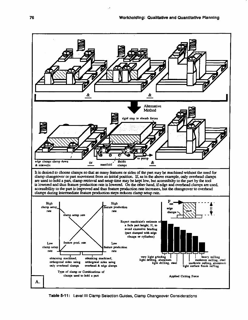
76 Workholding: Qualitative and Quantitative Planning
I I
It is desired to choose clamps sothat as many features or sides ofthe part maybe machiaedwithout the need for clamp changeover or part movement from an initial position. If, as in the above example, only overhead clamps are used to hold apart, clampreaieval and setup time maybekeptlow, but accessibilty to h part by the tool islowexedandthusfeatureproductionrateislowered. Ontheotherbaud,ifedgeandoveIfieadclampsareused, accessl'bility to the part is improved and thus feature production rate incmses, but the changeover to ovehead clamps during i n t e w feature productian steps reduces clamp setup rate.
""4' edge Fmzx t High High
Eatwe production
_ - . dunpr rate damp letup late
Expert machinist's estimate oi a Safe part height, €i, to avoid excessive bending @ut damped with edge
clunpr or cylillden)
LLm fuhm production
rate I I I I
obtaining rnackned, obuihing machined, artbogonal sides using ath0gm.l sides using light drilling, steel moderate milling, aluminum only overhead damp werhud dt edge dunpf light surface finish milling
Type of damp or Combinations of clunpf d to hold a put Applied Cutting Farce
Table 5-11 : Level 111 Clamp Selection Guides, Clamp Changeover Considerations
Workholding: Qualitative and Quantitative Planning 77
5.1.1.3. Clamp and part placement module In conjunction with decisions that have to be made regarding features to be machined and clamps to
be used, another bit of information is needed to define the part production state; the positions of the clamps about the workpiece and the position of the workpiece on the locating devices or fixture bed.
The Level I Clamp and Part Placement guides are universally applicable to all machining and clamping situations and are consequently termed global clamp and part placement guides.
A part’s location on a fixture bed must be known relative to some reference point. Table 5-12 Level I, Guide A, shows the qualitative tradeoffs that are entailed when deciding upon a part location method. Accuracy must be traded off against approximate production rate and maintenance of the undeformed state of the part. The position of the workpiece with respect to datum surfaces must be known, because every tool path is generated in relation to the part’s home-position.
An obvious rule, albeit one often broken inadvertently, is that a clamp should never interfere with the path of a cutting tool, Level I, Guide B. Violation of this rule renders any plan to successfully.machine a workpiece almost useless.
While the Level I clamp and part placement guides apply to all situations, the Level I1 guides in Table 5-14 are directed toward eliminating or reducing specific effects that might damage a part; buckling, compressive yielding, excessive bending, or loss of resistance to movement. Because this set of Level ll guides addresses an array of problems, the group may be referred to as problem specific clamp and part placement guides.
A workpiece might be initially situated such that clamping or cutting forces would cause part bending. in some instances, a certain amount of bending may be allowed within the limits established by the yield stress of the part material and the maximum part deflection set by the accuracy specifications for the part. It is strongly recommended, however, to reduce the amount of part bending as much as possible. Level II, Guide A, shows that this may be achieved by clamping over rigid part sections and by adding external supports adjacent to nonrigid part sections, or by applying only light clamping loads. These options must be compromised with part setup time and resistance to machining forces respectively.
Guide B illustrates methods to avoid part buckling problems and the consequences of such methods. Part reorientation in a vise and a reduction of tool feeds and depths of cut may lower the chances of buckling, but such measures reduce part production rates.
Level II Guides C, D, and E propose methods to prevent clamps from deforming the workpiece while providing sufficient resistance to cutting forces. Adding extra stops to absorb tool forces, distributing the total clamping load over a larger area, reducing tool feeds and depths of cut, and minimizing the distance between tool force vectors and clamp positions are several common ways to achieve this goal. Again, all of the possible fixes to the problem may carry drawbacks such as reduced accessibility to the part and slower production rates.
The Level I l l clamp placement guides in Table 519 propose methods to simplify tool path programming by striving for symmetrical part placement in clamps, Guide A, and to minimize part movement during intermediate production steps, Guide B. These Level 111 clamp and part placement efriaency guides are to be considered only after the Level I and II guides applicable to a planning step have been satisfied.
78 Workholdfng: Qualltative and Quantltatfve Planning
Part setup or clamping problem and human's solution to rectify it I
, good quality rolled or machined stock
b r:& I magnified view of+' . surface roughness .
m w e d view of surface roughness
very poor stock, casting, or forging - - - ' \ - - - .
3 contacts* formin
0 0 0 0
I I/
3-2-1
v I I
I I I I I t I I I I
I spherical button (flat) Vee I
* Often used types of locators that contact part I I . . . . . . . . . . . . . . . . . . . . . . . . . . .
When poor quality stock, castings, or forgings are to be located, the number and area of part contact
points should be minimized Instead of locating dircctly off of a flat surface. hardened spherical pins anc a special tooling plate may be used to achieve adequate part positioning with a minimum number of contacts and contact area. The gain in positional accuracy is obtained at the expense of increased part setup time.
Approximations or tradeoffs corresponding to clamping problem
Chart more applicable to "rough" parts, e.g. castings
High - 4ccuracY
LOW
iccuracv I
High - - I7
part located with part located with min. # of contacts redundant contacts Area of Contact between locators & part
Part location Maintenance of
Low - --
- High 'roductio
Rate
LOW
'roductioi - Rate
100 8
undeform. Part
Raint. of
0 % Maint. of undeform.
Q=Qy
part loca&d with part Iodated with min. # of contacts redundant contacts
Area of Contact between locators & part for a given applied clamping force
h e 3-2-1 locating principle may be bypassed without the iignifcant loss of part locational accuracy for reasonably pod stock. In lieu of the minimum 3 contacts, a flat :urface with essentially infinte number of contacts mal le used as the principle datum plane; clamp forces will be :verily distriiuted and the undeformed part state upheld. 'arts with rough surfaces must NOT be redundantly located 3 point contacts) or else instability occurs. Setup time llso increases when tooling plates & locating pins must IC used instead of merely placing a part on a flat surface.
Table 5-12: Level I Clamp Placement Guides, Part Location and Deformation Considerations
Workholding: Qualitative and Quantitative Planning 79
When parts are clamped in a vise, they must be extended far enough above the vise jaws so that there will be no interference between the path of the cutting tool and the jaws. This may be achieved by using I additional Darallel supports to prop the piece above the critical height level.
When parts are clamped to a machine tool bed with toe clamps, the toe clamps must not obscure the path of the cutting tool. If a T-slotted tool bed is utilized, the clamps may be shifted along the slots to avoid tool-clamp interference. The same holds true for fmture plates with holes and taps for clamps.
Table 5-1 3: Level I Clamp Placement Guides (cont.), Part-Clamp Interference Considerations
80 Workholding: Qualitative and Quantitative Planning
Part setup or clamping problem and human's solution to r e c q it I
I '4- part bending
or
Approximations or tradeoffs corresponding to clamping problem
Maintenance of UNBm part state - High --
Maint. of inbent part
, Rate
LOW
faint. of-$ , I 1
nbent part critical p L areas critical bart areas
supported with not supported with shims or blocks shims or blocks
Chart applicable to parts that are NOT supported over critical areas, and arc clamped with toe clamps
oppose clamp loads. An alternative is to clamp over rigid sections of the part even if the clamps obstruct features. and then to shift them to complete the feature.
100 %
unbent Part
MaintT
0 % Maint, unbent Part
\ Maintenance of
Resistance to machining forces,
I 2500
Applied Toe Clamp Force
Shims and support blocks increase the effective contact area between the part and the clamping system; bending stresses arc reduced, hence the unbent part state wil l be maintained under loading. However, the use of extra pa supports increases setup time (decreases production rate) If the critical arcas of a part are NOT supported by shim or support blocks. then a tradeoff must be made between maintenance of the unbent part state and resistance to machining forces, both functions of applied clamp load.
Workholding: Qualitative and Quantitative Planning 81
Part setup or clamping problem and human's solution to rectify it I
When a thin part is clamped in a vise. changes in its orientation in the vise may reduce or eliminpte
buckling problems but may also increase setup time by adding extra steps to the setup plan for the part. Cutter forces may produce large part bending or buckling stresses and deflections. Lowering feed rates and depth of cut redcue cutting forces and thus part strcsses, but these actions will also slow production rate.
Table 3-13 : Level 11 clamp riacement
Approximations or tradeoffs corresponding to clamping problem
m k Maint. unbucb
Part
0 % Maillt, mbuck Part
6.0
1/8 114 3/8 1/2 Part thickness, t (inches)
d
C 2 4000 3
Maintenance of .L(
3. 3000 5
h UNBUcKLm part state Resistance to -
machining I! forces in vise; I2
a - 2000 2 0
CI
II
v
- looog 0 8 c) c4 .r(
a D 5000 10000
Applied Vise Clamping Force
to slip Part Resist~nce to Slippage - for a given applied
Production Rate
- High prod. rate
LOW
-prod. ral
Metal removal rate; function (feed. depth of cut) Resistance to buckling increases with decreasing inter-jaw mrt length and increasing part thickness. Sufficient clam roorce must be applied to the part to prevent part slip. 3ccreases in metal removal rate reduce the chance of part slippage for a given vise force but slow production rate.
des pmt.), rart Buckling Gonsiderations I
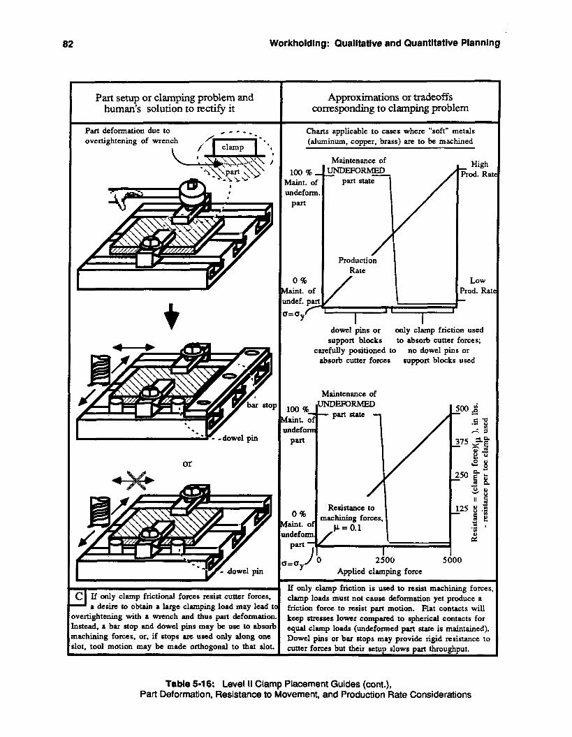
82 Workholdlng: Qualitative and Quantitative Planning
1 Part deformation due to c - - - -
Part setup or clamping problem and human's solution to rectify it I
C If only clamp frictional forces resist cutter forces, A a desire to obtain a large clamping load may lead tl overtightening with a wrench and thus part &formation Instead. a bar stop and dowel pins may be use to absort machining forces. or, if stops arc used only along one slot, tool motion may be made orthogonal to that slot.
overtightening of wrench ,...y-i -. , I clamp *
I - - K -dowel pin
I or
Approximations or tradeoffs corresponding to clamping problem
Charts applicable to cases where "soft" metals (aluminum, copper. brass) are to be machined
100%- Maint. of undeform,
Part
0 % laint. of mdef. pall r= cy F
Maintenance of
Production Rate I
/ I
High Frod. Rai
LOW
?rod. Rat - dowel pins or
support blocks carefully positioned to absorb cutter forces
only clamp friction used to absorb cutter forces;
no dowel pins or support blocks used
Maintenance of
t=Qy 2506 5000 Applied clamping force
If only clamp friction is used to resist machining forces clamp loads must not cause deformation yet produce a friction force to resist part motion. Flat contacts will keep stresses lower compared to spherical contacts for q u a l clamp loads (undeformed part state is maintained). Dowel pins or bar stops may provide rigid resistance to cutter forces but their ~etun slows art throuehnut.
Table 5-16: Level II Clamp Placement Guides (cont.), Part Deformation, Resistance to Movement, and Production Rate Considerations
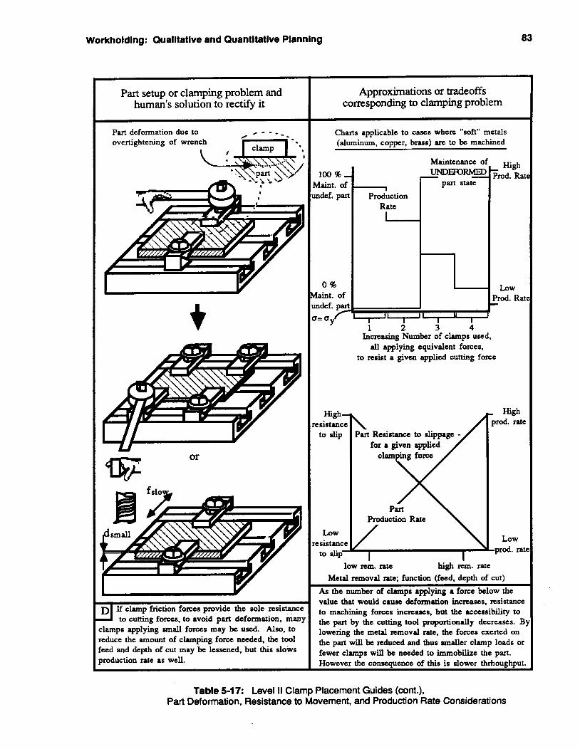
Workholding: Qualitative and Quantitative Planning 83
Part setup or clamping problem and human's solution to rectify it I
T a t i o n due to c - - - _ overtightening of wrench
Y or
If clamp friction forces provide the sole resistance to cutting forces, to avoid part deformation, many
clamps applying small forces may be used. Also, to reduce the amount of clamping force needed, the tool feed and depth of cut may be lessened, but this slows production rate as well.
Approximations or tradeoffs corresponding to clamping problem
Charts applicable to cases where "soft" metals (aluminum, copper, brass) arc to be machined
100%- Maint. of uldef. part
0 % faint. of urdef. part I= Qy T
High- esistance to slip
LOW
esistancc to slip-
Maintenance 01
I Production
I
I 1 I 1 I I I '+ 1 2 3 4
Increasing Number of clamps used, all applying equivalent forces,
to resist a given applied cutting force
\ Part
for a given applied clamping forcc
\ Production Rate
/
High ,rod. Rat -
LOW
)rod. Rat -
High ?rod. rate
Low .prod. rat
low rem. ratc high rem. rate Metal removal rate; function (feed, depth of cut)
As the number of clamps applying a force below the value that would cause deformation incmses, resistance to machining forces increases, but the accessibility to the part by the cutting tool proportionally decreases. B lowering the metal removal ratc, the forces exerted on the part will be r e d u d and thus smaller clamp loads or fewer clamps will be needed to immobilize the part. However the consequence of this is slower thrhoughput.
Table 5-17: Level II Clamp Placement Guides (cont.), Part Deformation, Resistance to Movement, and Production Rate Considerations
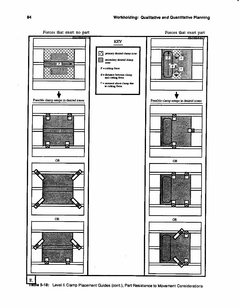
*
84 Workholding: Qualitative and Quantitative Planning
Forces that exert no part m
Possible clamp in desircd zones
I
I
OR I
KEY - Forces that exert part
Possible clamp set& in desired zones
d e 5-18: Level I I Clamp Placement Guides (cont.), Part Resistance to Movement Considerations
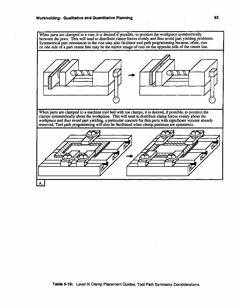
Workholding: Qualitative and Quantitative Planning 85
When parts are clamped in a vise, it is desired if possible, to position the workpiece symmetrically between the jaws. This will tend to distribute clamp forces evenly and thus avoid part yielding problems. Symmetrical part orientation in the vise may also facilitate tool path propamming because, often, cuts on one si& of a part center line may be the mirror image of cuts on the opposite side of the center line.
0 0 When parts are clamped to a machine tool bed with toe clamps, it is desired, if possible, to position the clamps symmetrically about the workpiece. This will tend to distribute clamp forces evenly about the workpiece and thus avoid part yielding, a particular concern for thin parts with sigmficaut volume already removed. Tool oath promammim will also be facilitated when clamp oositions are symmetric.
Table 5-19: Level 111 Clamp Placement Guides, Tool Path Symmetry Considerations
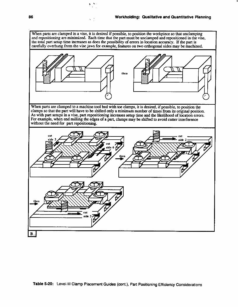
86 Workholding: Qualitative and Quantitative Planning
When parts are clamped in a vise, it is desired if possible, to position the workpiece so that unclamping and repositioning are minimized. Each time that the part must be unclamped and repositioned in the vise, the total part setup time increases as does the possibility of errors in location accuracy. If the part is carefully overhung from the vise jaws far example, features on two orthogonal sides may be machined.
then
When parts are clamped to a machine tool bed with toe clamps, it is desked, if possible, to position the clamps so that the part will have to be shifted only a minimum number of times from its on@ position. As with part setups in a vise, part repositioning increases setup time and the likelihood of location errors. For example, when end milling the edges of a part., clamps may be shifted to avoid cutter interference without the need for part repositioning.
Table 5-20: Level ill Clamp Placement Guides (ant.), Part Positioning Efficiency Considerations

Workholdlng : Qualitative and Quantitative Planning a7
5.2. Summary of Contributions This work has presented several major contributions to the general understanding of fixture design,
placement and selection. A novel control structure integrates quantitative and qualitative information for intelligently
0 Prominent qualitative information utilized by expert machinists has been identified, such as
0 This knowledge has been categorized into hierarchical levels, which can be used in planning
planning fixture tasks.
standard practices, tradeoff s, and discrete approximations.
and control.

88 Workholding: Qualitative and Quantitative Planning
Novel Tools for intelligent Machining 89
6. Novel Tools for Intelligent Machining The Intelligent Machining Workstation (IMW) is being designed to be virtually self sufficient. For
example, it may be used in a stand-alone environment machining products on the U.S. space station or it may be just one component of a large flexible manufacturing system. In either case, it is expected to control and operate its own environment, even in modes of failure. To accomplish this ambitious goal, we are designing and implementing novel tooling, which can be used to manipulate and sense the complete machine tool environment. '
6.1. The Flexible Clamping System (FLECS) philosophy As a first step, we are building a flexible clamping system that will be automatically planned for each
part style and then automatically constructed by the machine tool itself.
6.1 .l. Fixturing
maintaining accurate and viable holding characteristics. One goal of the RECS system is to handle a great variety of part types, as simply as possible, while
From figure 6-1, there are a range of clamps that vary from very flexible clamps which can hold almost any part (e.g., phase change clamps) to specially constructed fixtures which can only hold one part style. Unfortunately, this advantage of breadth trades off on the ability to positively locate the part, which is necessary for very accurate machining.
I
Phasechange Toeclamps vise Dedicated Clamps Fixtures
Figure 6-1: Range of clampable parts vs. Difficulty of positive location
The clamp style that best compromises between difficulty and variety is the toe clamp, and this is the clamp style that currently is being used by the FLECS system. The toe clamps are also capable of immobilizing a vise, so this modality is supported. It is possible to decompose the fixturing problem into two separate, independent problems: part location, and part clamping.
90 Novel Tools for Intelligent Machining
6.1.2. Environment Conventional wisdom states that as volume demand for one part increases, special tooling costs will be
reduced on a per part basis. Since this special tooling is easier to use, after it's designed and manufactured, it increases throughput by reducing the time the machine tool's spindle is idle.
However, the IMW has a very different assignment; here, the goal is not to make as many parts right as possible, as quickly and inexpensively as possible, but rather to make "a good part right the first time." Hence, the IMW seeks to optimize part quality at the expense of throughput. This corresponds appropriately to the way oneoff parts are produced in job shops. Any competent machinist takes the extra time required to do the job right the first time.
Every time the part is moved, the referenced dimensions change. If the part is removed from the clamps, it must be positively located again. There is always a strong possibility that the new reference values relative to the datum surfaces will deviate by whatever tolerances are built into the tool and measuring instrument. Thus, even the use of an automatic pallet changer will affect machining accuracy, no matter how precise it is. In other words, it is far superior for the workpiece to remain in the clamps for as long as productive work can be accomplished. Therefore, in a oneoff environment, manipulation and inspection tasks should be performed by the machine tool itself.
By including manipulation and inspection in the repertoire of the machine tool, a new form of machining center is conceived. The design of this machining center is tailored to represent a compromise between the design constraints of a machine tool, coordinate measuring machine, and robot.
6.2. Implementation methodology
6.2.1. Novel tooling Novel tools, grippers and inspection devices, have nothing in common with traditional metal cutting
tools except for the fact that they are both mounted in the spindle of the machine tool and are stored in the same tool drum. The manipulation task leads to the need for a gripper that can be operated while in the spindle. This gripper is illustrated in figure 6-2. The inspection task necessitates the design of a spindle mounted camera. Other tools may include a brush to clear chips off of the tool table, a three degree of freedom wrist and a grinding wheel. A coupler is needed to pass electrical and pneumatic lines to these new tools and is the yellow box in figure 6-2.
A major challenge in the design of this tooling is accommodating it in the tool drum of the 5vc. The tools must fit in a cylindrical envelope that is 4 inches in diameter and is 12 inches long. In a NC machining center designed to accommodate these tools, a special tool drum would greatly simplify the tool designs and would be more amenable to the tool's special storage requirements.
6.2.2. Position measurement methods The position of the workpiece in the machine tool frame of reference must be measured with a smaller
tolerance band than that of it's features. This tolerance is communicated through the drawing of the part to be machined.
The IMW project seeks machining accuracies of +.001 inch. Since the nominal accuracies of the machine tool are 5.0005 inch positioning accuracy and .0002 inch repeatability, it should be possible to achieve this goal.
Novel Tools for Intelligent Machining 91
flgure 6-2: Gripper mounted in spindle
6.2.2.1. Touch probe Two types of position sensing probes are being investigated. The first is a Valeron touch probe that is
offered as an option for the wc. The software that accompanies the probe enables an operator to correct for translational errors in part or fixture position by shifting the coordinate axes by the appropriate amount. It does not account for orientation errors. The touch probe is functionally an automated edge finder, with the additional capacity of Yramming a part,’ or determining height relative to the tool table. The probe can rapidly detect when It hits an object and signal the machine tool through infrared telemetry. In manual mode, an operator can jog the tool table until a hit is detected, at which time that point’s coordinate values can be read off the CRT screen. The operator can then reset them as necessary, just as the edgefinder is used. The same process can be performed in automatic mode provided that the object is reasonably close to its expected position.
Tests conducted in the laboratory indicate that the touch probe is capable of measuring positions to the same accuracy as the machine tool, namely 50005 of true position, under the most favorable conditions. These conditions include calibration to reduce stylus runout, approaching the object in the device’s most sensitive direction, using a short stylus and approaching the object at a slow speed. Work has been done at the University of Wisconsin to use the the 5vc as a Coordinate Measuring Machine (CMM) by making improvements to the machine tool’s sew0 system. Hopefully, this work can be incorporated in some future revision of the system.
92 Novel Tools for Intelligent Machining
Figure 6-3: The Valeron touch probe
6.2.2.2. Machine vision A seconid approach, to coordinate measurement, is to use machine vision to measure the workpiece.
A CCD camera is mounted on a servo controlled platform with tilt and pan axes (see figure 6-1 1). The assembly is stored in the tool drum of the wc and can be automatically mounted in the machine tool to provide the camera with a total of 5 degrees of freedom. The design and operation of the tiiffpan staging will be discussed later. The machine vision approach offers the advantages of flexibility and efficiency. If the tolerances needed on a measurement are not particularly tight, the field of view of the camera can be increased, and several measurements can be performed simultaneously. For stringent measurements, an initial reading can direct the controller to a location close tu the final measurement where a much smaller field of view can achieve the desired accuracy. The CCD sensor has a resolution of 510 x 492 pixels. The accuracy of any measurement will be proportional to the size of the field of view. For example, If the field of view is 0.5 inch then the resolution of the sensor will be .001 inch. However this does not guarantee that the measurement will be accurate to that amount. Machined edges are often either rough, uneven and burred, or rounded to such a large radius that the image of the edges blur due to surface specularities. In addition, some internal feature locations, such as depths and diameters of stepped holes, are difficult to measure without special lighting.
Both of these approaches require that the FLECS controller know the position of the machine tool's three axes. The 5vc machine tool controller does not support requests for this data from external controllers; it will only output the data to the operator's console. The approach used at the University of Wisconsin solved this problem by adding hardware and software patches to the machine tool. However, this is a complicated process and is specific to one version of one model of machine tool controller. Hence, the FLECS project will rely on redundant measuring systems retrofitted on the machlne9ool's three axes. Linear encoders offer sufficient resolution for the system requirements, are not prohibitively expensive and can be easily mounted. If the resolution of the measuring system is superior to that of the machine tool, the machine tool could use the measuring system to perform self-calibrations prior to very high precision cuts.
Novel Tools tor lntelllgent Machining 93
6.2.2.3. Using the data Six measurements of three orthogonal reference surfaces on the part can be used to locate prismatic
parts. The "3-2-1" principle states that knowledge of three points, defining the plane of one surface, along with a line and a point on the other two surfaces, respectively, constitute sufficient data for positive locat ion.
Once the position of the part has been determined, it is possible to calculate a transform that maps the part model into the actual machine tool space. This transform can be stored in a CAD database or implicitly in the NC code. For example, the transform can be applied to the NC code so that the planned cutter paths are consistent with the actual location and orientation of the workpiece.
6.2.3. Clamping technique Figure 6-4 illustrates the toe clamps that are currently used in the FLECS system. The clamps consist of
two hydraulic actuators: one used to secure the clamp to the table, and another to clamp the part to the table. Radially expanding bushings, part number five in the figure, can be inserted into any of 99 holes located on one inch centers in the tool table. Helical clamps travel 90 degrees while bearing down on the part. Compression sensors on the clamp arms, part #2b, measure the clamping force and can be used to provide set point limits, thereby avoiding excessive part deflections and deformations. The system has also been used in conjunction with a hydraulic vise (see figure 6-5). The numerous mounting locations for the clamps account for the high configurability of the system; prismatic parts up to 10 inches x 8 inches x 2 inches can be accommodated.
6.2.4. Self-manipulation The machine tool is a device capable of motions in the three coordinate directions. Its structure is
sufficiently rigid to withstand continuous cutting forces of up to 2000 pounds in the vertical direction and 1000 pounds in the horizontal direction. It follows that the machine should be capable of manipulating large objects within its working envelope by using a gripper in the spindle. Such a device has been built and consists of a connection adapter, axial insertion force sensor, Remote Center of Compliance device (RCC), gripper, and limit switches. It is illustrated in figure 6-10.
6.2.5. The gripper The gripper can grasp clamps, each weighs eight pounds, and insert them into hole locations in the
tool's table. In use, the gripper is inserted in the spindle of the wc, it is then moved over the gripping nub of the clamp and is slowly lowered into grasping position. A limit switch on the gripper senses when it is in the proper position at which point the jaws close on the nub. Hall switches on the gripper detect whether the jaws have closed properly. The compression sensing bridge detects jam forces, thus providing a second defense against the gripper crashing into the table. Once properly gripped, the clamp is positioned over the chosen hole and a similar process of checking for jam forces and clamp location is performed. This time the limit switch is on the face of the clamp that seats against the tool table, thus telling the system when the clamps have been properly lowered into position.
6.2.6. Robot integration The current gripper is neither capable of lifting the raw stock nor reaching outside of the nominal
machine tool workspace. Therefore, an available Cincinatti Milacron p robot is being used to lift parts onto the tool table. This robot is an experimental setup that will probably not be practical in the industrial environment.
94 Novel Tools for Intelligent Machining
n r- 6
Figure 6-4: Hydraulic FLECS swing arm clamps
Novel Tools for Intelligent Machining 95
Figure 6-5: FLECS system clamping a hydraulic vise.
6.3. System details
6.3.1. Overview and design philosophy The design philosophy of the RECS system emphasizes modularity, ruggedness, and adherence to
industrial conventions, in both hardware and software. Modularity is essential in a project of this scope since it is an ongoing effort in which many individual systems will be revised or replaced either due to initial plan or design review. Thus, the mechanisms incorporate reconfigurability, adjustability, and quick connectability. The software, written in c, is highly structured with standard communications across hierarchical layers. Rugged design is called for in the machining environment where chips, coolant, and other debris are often present. In controls, ruggedness is manifested through ample use of sensors and feedback (including operator feedback during initial system debugging) to insure that no life threatening or machine damaging situations develop. Standard industrial practices concerning documentation, design and manufacture are important so that the work done in this project is credible, repeatable, and easy to debug.
The milling machine controls have been modified to allow limited external control after it has been manually initialized. Initialization includes powering up the system, aligning the tool changer and slides, and bringing the operator console display to a specific state. One mechanical alteration was made, which adds a coupler to the machine tool so that electrical power, control signals, and pneumatics can be passed between the novel tooling and the machine tool. Installation of a secondary axis position measurement system, the linear encoders, is also planned. The two novel tools that use these service connections, the gripper and camera tilt/pan platform, are stored in the tool drum, along with the touch probe and the normal complement of machining cutters. The subplate assembly includes the tool table and four hydraulic clamps. This subplate is lowered into position with an overhead crane and completely covers the 5vc tool bed. Two hydraulic and two electrical connectors on the subplate assembly must be manually coupled to the rest of the FLECS system.
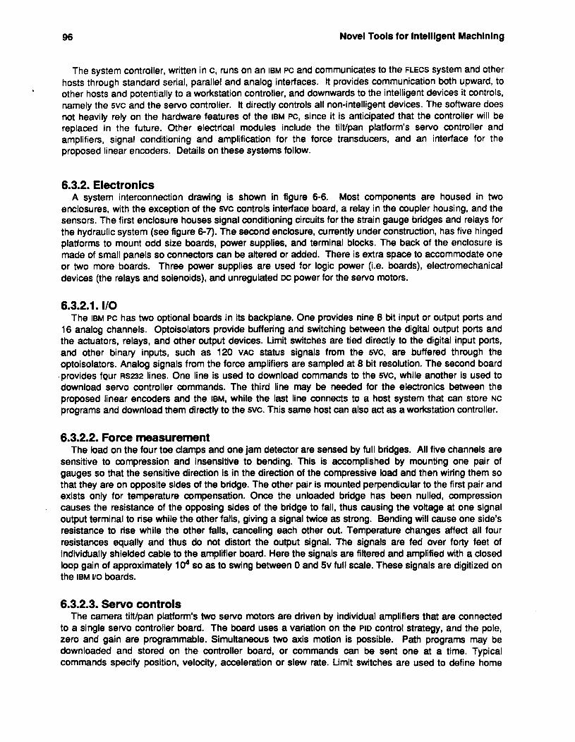
96 Novel Tools for Intelligent Machining
The system controller, written in c, runs on an IBM PC and communicates to the FLECS system and other hosts through standard serial, parallel and analog interfaces. It provides communication both upward, to other hosts and potentially to a workstation controller, and downwards to the intelligent devices it controls, namely the 5vc and the servo controller. It directly controls all non-intelligent devices. The software does not heavily rely on the hardware features of the IBM PC, since it is anticipated that the controller will be replaced in the future. Other electrical modules include the tiltlpan platform’s servo controller and amplifiers, signal conditioning and amplification for the force transducers, and an interface for the proposed linear encoders. Details on these systems follow.
6.3.2. Electronics Most components are housed in two
enclosures, with the exception of the 5vc controls interface board, a relay in the coupler housing, and the sensors. The first enclosure houses signal conditioning circuits for the strain gauge bridges and relays for the hydraulic system (see figure 6-7). The second enclosure, currently under construction, has five hinged platforms to mount odd size boards, power supplies, and terminal blocks. The back of the enclosure is made of small panels so connectors can be altered or added. There is extra space to accommodate one or two more boards. Three power supplies are used for logic power (i.e. boards), electromechanical devices (the relays and solenoids), and unregulated DC power for the servo motors.
A system interconnection drawing is shown in figure 6-6.
6.3.2.1. I/O The IBM PC has two optional boards in its backplane. One provides nine 8 bit input or output ports and
16 analog channels. Optoisolators provide buffering and switching between the digital output ports and the actuators, relays, and other output devices. Limit switches are tied directly to the digital input ports, and other binary inputs, such as 120 VAC status signals from the wc, are buffered through the optoisolators. Analog signals from the force amplifiers are sampled at 8 bit resolution. The second board .provides fqur ~ ~ 2 3 2 lines. One line is used to download commands to the 5vc, while another is used to download servo controller commands. The third line may be needed for the electronics between the proposed linear encoders and the IBM, while the last line connects to a host system that can store NC programs and download them directly to the 5vc. This same host can also act as a workstation controller.
6.3.2.2. Force measurement The load on the four toe clamps and one jam detector are sensed by full bridges. All five channels are
sensitive to compression and insensitive to bending. This is accomplished by mounting one pair of gauges so that the sensitive direction is in the direction of the compressive load and then wiring them so that they are on opposite sides of the bridge. The other pair is mounted perpendicular to the first pair and exists only for temperature compensation. Once the unloaded bridge has been nulled, compression causes the resistance of the opposing sides of the bridge to fall, thus causing the voltage at one signal output terminal to rise while the other falls, giving a signal twice as strong. Bending will cause one side’s resistance to rise while the other falls, canceling each other out. Temperature changes affect all four resistances equally and thus do not distort the output signal. The signals are fed over forty feet of individually shielded cable to the amplifier board. Here the signals are filtered and amplified with a closed loop gain of approximately 104 so as to swing between 0 and 5v full scale. These signals are digitized on the IBM VO boards.
6.3.2.3. Servo controls The camera tiWpan platform’s two servo motors are driven by individual amplifiers that are connected
to a single servo controller board. The board uses a variation on the PID control strategy, and the pole, zero and gain are programmable. Simultaneous two axis motion is possible. Path programs may be downloaded and stored on the controller board, or commands can be sent one at a time. Typical commands specify position, velocity, acceleration or slew rate. Limit switches are used to define home
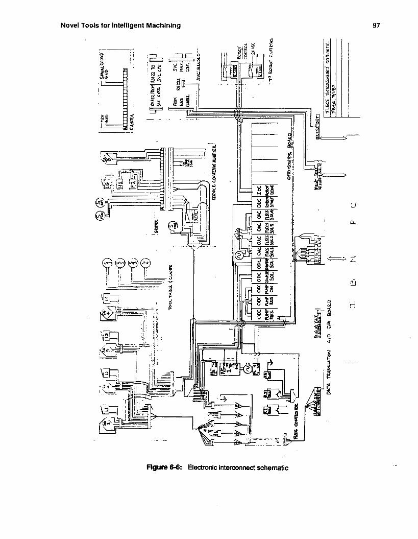
Novel Tools for Intelligent Machining 97
I
J f 'U.
w I z
i. d
Flgure 6-6: Electronic interconnect schematic
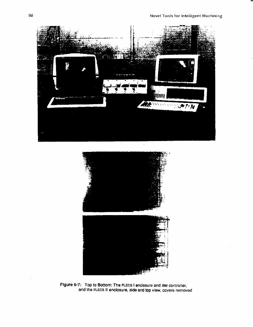
98 Novel Tools for Intell igent Machining
Figure 6-7: Top to Bottom: The RECS I enclosure and IBM controller, and the FLECS I I enclosure, side and top view, covers removed
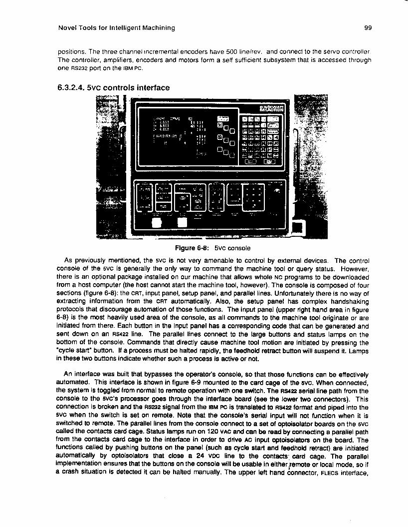
Novel Tools for Intelligent Machining 99
positions. The three channel incremental encoders have 500 linehev. and connect to !he servo controller. The controller, amplifiers, encoders and motors form a self sufficient subsystem that is accessed through one RS232 port on the I ~ M Pc.
6.3.2.4. 5vc controls interface
Figure 6-8: 5vc console
As previously mentioned, the 5vc is not very amenable to control by external devices. The control cons& of the 5vc is generally the only way to command the machine tool or query status. However, there is an optional package installed on our machine that allows whole NC programs to be downloaded from a host computer (the host cannot start the machine tool, however). The console is composed of four sections (figure 6-8): the CRT, input panel, setup panel, and parallel lines. Unfortunately there is no way of extracting information from the CRT automatically. Also, the setup panel has complex handshaking protocols that discourage automation of those functions. The input panel (upper right hand area in figure 6-8) is the most heavily used area of the console, as all commands to the machine tool originate or are initiated from there. Each button in the input panel has a corresponding code that can be generated and sent down on an ~5422 line. The parallel lines connect to the large buttons and status lamps on the bottom of the console. Commands that directly cause machine tool motion are initiated by pressing the "cycle start" button. If a process must be hafted rapidly, the feedhold retract button will suspend it. Lamps in these two buttons indicate whether such a process is active or not.
An interface was built that bypasses the operator's console, so that those functions can be effectively automated. This interface is shown in figure 6-9 mounted to the card cage of the 5vc. When connected, the system is toggled from normal to remote operation with one switch. The R S 2 2 serial line path from the console to the svc's processor goes through the interface board (see the lower two connectors). This connection is broken and the RS232 signal from the IBM Pc is translated to RSZ? format and piped into the 5vc when the switch is set on remote. Note that the console's serial input will not function when it is switched to remote. The parallel lines from the console connect to a set of optoisolator boards on the 5vc called the contacts card cage. Status lamps run on 120 VAC and can be read by connecting a parallel path from the contacts card cage to the interface in order to drive Ac input optoisolators on the board. The functions called by pushing buttons on the panel (such a$ cycle start and feedhold retract) are initiated automatically by optoisolators that close a 24 VDC line to the contacts-. card cage. The parallel implementation ensures that the buttons on the console will be usable in eitherfemote or local mode, so if a crash situation is detected it can be halted manually. The upper left hand connector, FLECS interface,
100 Novel Tools for Intelligent Machining
flgure 6-9: 5vc interface board
connects parallel m signals from the IBM'S digital ports. The fourth connector connects the interface to the 5vc. Power for this board comes exclusively from the wc.
The final link to the 5vc is the extraction of slides position information. It is anticipated that the three linear encoders will be connected to a counter board that will be situated in the FLEW enclosure II. With a maximum travel of 35 inches and .0005 inch resolution, at least 17 bits will be needed to communicate that position to the 5vc. Hence three 8 bit input ports are resewed for this system, along with one serial line that may receive the requests from the IBM. -
6.3.3. Software This section briefly describes the first implementation of various IMW modules. Future software designs
.will call for distributing the intelligence between the machine tool controller and the workstation controller. And seconndly, it will be necessary to significantly reduce the granularity of internal messages between them: currently complete NC programs are downloaded to the machine tool whereas in the future we would like to limit the communications to single product data features.
6.3.3.1. Typical production sequence The controller's main function is to supervise the automatic assembly of reconfigurable clamps
arranged to form a fixturing device. A typical sequence commences with the host downloading a request to fixture a part. The controller then retrieves it's model of the part's raw form and process steps, or requests it from the host. The controller flags the robot to start loading remotely located stock onto the tool bed. Once the robot has sent a finished signal, the touch probe or vision system measures the actual position of the part, compares it with model of the size of the object at that particular stage of it's manufacturing process, and determines a transformation between coordinate frames. This relation is then used to alter the NC code so that the reference dimensions in the two frames are in agreement. The probe is then swapped for the gripper. The gripper rapidly positions itself a short distance over a particular clamp that is accurately located in it's platform. It then descends until a jam force is detected or the limit switch on the gripper indicates that It is in position. The jaws of the gripper close, the clamp Is lifted out of the platform, and it is rapidly positioned over a hole in the tool bed. The clamp is slowly lowered into the hole until a jam force is detected or the limit switch on the clamp base closes, indicating that the clamp is fully inserted. Compliance is provided during this operation by the RCC. This process is repeated for the
Novel Tools for Intelligent Machining 101
other three clamps. The hydraulic clamps are then actuated. The solenoids are kept open until the individual force setpoints are reached. The transformed NC code is subsequently downloaded and machining commences.
6.3.4. Software features The software is built up of hierarchical layers, thus decomposing the tasks into much simpler and more
manageable subtasks. At the top layer, a menu appears on the screen offering options to the operator so that all of the functions can be run and tested manually. Another option is to run a file that provides a sequence of high level commands such as: "load clamps to locations 1,2,3,4," "transform program #576" or "calibrate probe." This command file can be written by the operator, or it can be created and downloaded from a host computer. In the second level the task type and parameters are specified. The third level breaks the task into individual calculations, measurements and actions which are interpreted as port-level wo commands at the next level and sent out from the bottom layer. The only global data structure is used to describe the state of the machine tool and workspace, such as current slides position, tool in spindle, and clamp locations. A utility program updates this world model whenever a command that affects it is used.
The functions offered from the main menu are discussed presently. Note that vision processing is not performed by this program nor is it fully developed at present so the current system depends on the touch probe for location information.
0 Operate servosystem: This module feeds individual commands to the tiupan platform servo controller, or reads them from a command file, as well as testing system status. This command file comes from a vision processing system connected to the host.
.Inspect part: Touch probe calibration is offered to increase accuracy in measurement. Single locations and groups of points are tested for based upon expected measurements and ihe actual values are returned. The points to be tested for are entered by an operator or through a command file.
0 Load clamps: This provides the sequence of actions necessary to move clamps from their respective platforms to specific hole locations in the tool table.
Load part: This program initiates a request to the robot to run a fixed program to load a part on the tool table.
*Operate grlpper: From here the gripper can be 'manually" controlled to support experimentation and tasks other than loading clamps.
Operate clamps: Used to clamp part to specified force setpoints and unclamp part when done.
*Operate 5vc: Used to download individual commands, groups of commands, or part programs, to the machine tool.
Display or toggle status: Used to query the controls for the state of the machine tool, as is stored in the global data structure, as well as the state of the individual input ports, and also to change the state of individual outputs. This is helpful for debugging.
For the most part, the coding of these tasks is straightfoward. The only exception is the downloading of commands to the 5vc. The control console of the 5vc was designed to be used by an operator, reading the state of the menu on the console CRT. On the right side of the console screen, illustrated in figure 6-8, are a nine sets of four characters. Each character represents a different class of commands, so several classes are accessed from the same panel button. The buttons on the MDI (Manual Data Input) input panel closest to these characters sets select the active character by rotating the set until the desired code letter is in the leftmost position. The program must keep track of the state of the menu so that the proper command is selected.
102 Novel Tools tor Intelligent Machining
6.3.5. Mechanisms Custom designed devices for this project are divided into three groups. The novel tooling are those
devices that are mounted in the spindle of the machine tool, and include the gripper, titupan camera staging platform, and a brush for chip removal. A second group is the clamping system, including the tool table, clamps, and subplate. The third is for the supporting systems: The coupler, linear encoder mounts, and electronic enclosures. This is an evolving project and modularity and adjustability has been emphasized in the design since several parts will be upgraded in time.
6.3.5.1. Gripper
Figure 6-10: Gripper assembly
The gripper, shown in figure 6-10, consists of four arms that form a jaw, opening and closing based upon the direction of travel of the actuating cylinder. These jaws are designed to close onto external ridges of special gripping nubs mounted on the clamp. The nubs are counterbored to accommodate the mounting bolt and to guide the gripper's switch plunger, in case it was mislocated by a small amount. An RCC wrist mounted on the inboard side of the gripper provides the compliance to allow for these small
Novel Tools for Intelligent Machining 103
positional deviations. When the gripper contacts the nub, the switch plunger moves a small amount in the axial direction, tripping a limit switch that is used as a signal to the controller that the gripper is in proper position and the jaws may close. The plunger has some overtravel to assure that the machine tool has time to stop before a crash situation develops. Hall switches mounted on the cylinder sense the presence of the cylinder’s magnetic piston. This enables the system to confirm that the gripper jaws are fully retracted or extended. The gripper also has a full strain gauge bridge sensitive to compression that can detect jam forces.
The jaws are opened and closed by a double acting cylinder that pushes a slotted block across the axis of the spindle. The flanged shaft has a pin through it, and this pin follows the slot, thereby moving the shaft in the axial direction. The flange rotates all four arms simultaneously, thereby closing the jaws. A connection plate joins the gripper to a standard V-flange machine tool holder and serves as a platform for the connectors that must mate with the automatic coupler.
The greatest disadvantage of the current design is that there are no rotational degrees of freedom; rotations about the spindle axis would be particularly useful since the clamps cannot be reoriented at present. We hope to resolve this issue in future designs.
6.3.5.2. TiWpan staging platform A preliminary design drawing of the platform is shown in figure 6-11. tt is a two axis mechanism that
articulates a CCD camera in the tilt and pan directions. The most important consideration in the design of this camera staging is rigidity and accuracy. In order to measure dimensions to .W1 inch accuracy, it is crucial that the bearings be preloaded to avoid uncertainty in the position of the shafts. The component parts must also be square and perpendicular so that the position of the focal plane of the camera is known with respect to the machine tool coordinates. Once again size is a major factor since the mechanism must fit inside the tool changer. Vibrations from the 5vc could possibly affect the performance of the camera by causing blurred images, especially when the field of view is sufficiently small. Unfortunately, a solution to this problem would require some form of elastic mounting that would lessen the rigidity of the staging. At present, no vibration isolation is included in the design; if it becomes a problem isolation pads can be easily retrofitted.
Features of the platform include the drive components and bearings. One limit switch per axis is incorporated so that incremental encoders mounted on the motors can be initialized. The motors are compact and powerful; they have a torque constant of 8 oz-in/amp, which should give quick dynamic performance. The power is transmitted by a nylon chain with a steel core so that backlash will be limited to the stretching of the belt, which should be minimal. The gear ratios are 2.8:l for the pan axis and 2:l for the tilt axis. With the 500 line, 3 channel encoders installed the measurement accuracy will be on the order of one half a degree. The bearings used for the pan axis are especially critical since inaccuracies in that axis cause multiplied errors in the kinematic chain. Thus, a pair of bearings are used. These bearings can be radially preloaded by applying an axial force, locking the shaft in place. Two bearings are used for the tilt axis, also.
The design illustrated above is currently undergoing revisions because of cable management difficulties and other bugs that did not surface until manufacturing planning commenced. The solution to the cable management dilemma is to move the camera further down, so as to give some room, but then it does not fit into the tool changer. In lieu of that, we can substitute a different model of the camera where the cCD sensor and signal conditioning electronics are in separate packages.
This same design will serve as the basis for two other mechanisms that the IMW will need. For off- spindle vision sensing it will be desirable to have tilt/pan axes; here only the mounting will change. With the addition of a roll axis and gripper, the system turns into a fully articulated wrist, which can be applied to manipulation tasks.
104 Novel Tools for Intelligent Machining
. . .. . - - .
i I
.. . ,
- - . , . . . . . . . . -I - -- . . .
.. :.- 8 ; a.
Figure 6-1 1 : Design drawing of tiltlpan mechanism.
6.3.5.3. Clamping system
will be in a known position and orientation so that the manipulator can find them. The reconfigurable toe clamps discussed in the previous section are mounted in platforms so that they
Modifications to the original clamp design include the addition of adapters, or gripping nubs, to ease the task of grasping the clamps, the addition of limit switches to signal the controls when the clamps are properly seated on the tool table, and the use of a subplate to mount the tool table and ancillary parts (see figure 6-12). The subplate locates off of T-slots in the tool bed and thus only needs one measurement, in the X direction, to fix it3 position. Two electric and two hydraulic connectors can be quickly coupled. Each of the clamps is easily detached.
A special effort has been made to protect electrical cables and connectors from the harsh machining environment. The hydraulic system has two circuits. The small cylinders that actuate the radially expanding bushings are on a circuit that is pressurized when the pump is turned on. The main clamping
Novel Tools for Intelligent Machining 105
Flgure 6-12: Clamping subplate assembly
cylinders are on a second circuit that is filled after the first one has reached its pressure setpoint. Each clamp has a solenoid vahe that allows fluid to flow into it until its clamp force setpoint is reached, which can range up to lo00 pounds. The assembly is lowered onto the machine tool by an overhead crane. This approach has much of the modularity that an automatic pallet changer requires, so that it can hopefully be adapted easily should such an option become available for the S C .
6.3.5.4. Supporting systems The most important supporting system is the coupler assembty, illustrated in figure 6-13. This must
guide two slxteen pin electrical connectors and a pneumatic quick connect to proper insertion. The electrical connectors have "floating" mounts so that they can withstand misalignment up to 0.10 inch. One connector is for small signals including video from the CCD camera, while the other is used for electrical power and ground lines. When not in use, trap doors on the underside of the coupler protect the couplings from flying coolant and chips. A electrical solenoid is installed to disconnect the pneumatic connection when necessary. Also housed in the box is a relay to switch the gripper pneumatic forward and retract solenoids. The fasteners that hold parts, whose location is critical to successful insertion, are in slotted holes so that it is adjustable. Unfortunately, if the fasteners ever loosen, alignment is lost.
Other supporting systems include the electronic enclosures, previously mentioned, and mounts for the linear encoders. These encoders have not yet been selected and thus the mounting for them has not yet been designed. It is anticipated that they will be placed directly on the machine tool and that devising a way of measuring the relative motion of the slides should not be difficutt.
106 Novel Tools for Intelligent Machining
Figure 6-13: Coupler for novel tooling
6.4. Conclusions and future directions Currently the mechanical design portion of the FLECS system is almost complete. A revision of the
tilt/pan mechanism and the mounting arrangement of the linear encoders has not been completed. At present, the subplate assembly and coupler are almost complete, the new enclosure is still being machined and assembled, and the overhead track and trolley have been installed. The electrical interconnect schema needs revision and boards for the IBM Pc and servo control have not been procured. Also, the linear encoder interface has not yet been designed, but all other subsystems have been designed and procured. When the second enclosure is completed, wiring the interconnects can commence. Though 110 level software has been written and tested (we were able to control the clamping system through the IBM earlier this year), the majoriity of the task still remains. It is anticipated that the electrical and mechanical hardware will be in place by the end of 1987, except for the linear encoders. Software development and system testing/debugging will occupy the spring term.
The first revision to the initial designs will be a new tool table and clamp design. The clamps of present are too high and can only clamp in orthogonal directions. Also, the tool table is too small. Other changes are also planned and ideas currently in gestation will be developed in mid to late 1988. The FLECS controller should require no modifications for this new design. Another revision is to add a third axis to the gripper to make the machine tool into a fully articulating robot. Eventually, it will be useful to modify the machine tool's controller so that the gripper's six degrees of freedom can be controlled simultaneously.

Novel Tools for Intelligent Machlning 1 07
The IBM controller could then be abandoned, with its functionality incorporated into the controller of the machine tool. Finally, magazines for modular fixturing components must be designed so that they are within reach of the machine tool's gripper, and some better method of loading the raw stock should be considered.
The FLECS system will be useful for the automatic fixturing of parts in a range of production environments. It is anticipated that this work will lead to a new form a machining center that can manipulate, inspect, grind, clear chips, and, of course, machine parts. Such a machine tool might be called a "universal machining center," whose controller is configured so as to compromise between the various functions.

108 Novel Tools for Intelligent Machining
Evaluation of a Workstation Architecture 109
7. Evaluation of a Workstation Architecture
7.1. Introduction This chapter describes the work done in Phase I of the IMW project for evaluating computer hardware
and software for the development environment and the prototype IMW workstation controller.
7.2. Criteria In order to select suitable computer workstations, it is necessary to compare the relevant features. The
primary features considered in evaluating the workstations are: 0 Applications
0 Performance
0 Languages
0 Compatibility with existing facilities
7.2.1. Applications: Symbolic verses Real-Time Processing The IMW project entails the building of an expert system for machining. Expert systems have a strong
tie with the Lisp language. A large number of the expert systems and expert system shells have been built in Lisp. To concentrate the resources on designing the system, support for Lisp on the workstation is essential. Also required for this project is extensive utilization of sensors for monitoring the milling machine. The ability to interface (including having sufficient VO bandwidth) to a variety of sensors is essential to the chosen system. Lisp systems tend to be at odds with real-time systems. Lisps can be very large and powerful and taxing on memory usage, disk usage and disk access (speed). Large Lisp programs have a tendency to swamp the computer enough that servicing other requests (such as 110 from sensors) is inadequate. With contemporary technology, it is practical to separate the Lisp and the sensor processing onto different processors and have high-level communications between them.
There are two major classes of workstations: 1. Conventional architecture workstations are general purpose computers that support a wide
2. Lisp machines have specialized hardware to support fast, efficient lisp and have a large
variety of programming languages and tools.
integrated software environment to aid in rapid development and debugging.
Of the three major vendors offering Lisp machines, Symbolics Inc. and Texas instruments are the most widely available with Xerox coming in third. The major attractions of the Lisp machines are its sophisticated integrated environment and its good debugging facilities. The major detractions of the Lisp machines are the lack of support for other programming languages and its nonstandard window systems and graphics.
On the conventional side, there are many vendors with many different features and different ranges of cost and performance. Features offered cover color graphics, hardware graphics assistance, floating point accelerators, and vector processors. The Unix operating system and C programs dominate the workstation market. Two other operating systems that are widespread are Digital Equipment Corporation’s VMS and Apollo’s Domain system. The major attractions of conventional workstations are that the C programming language is fairly portable and that a common window system, X-Windows has wide vendor support. The major detractions are the Lisp performance is slower and the Lisp environments are primitive compared to the Lisp machines.
110 Evaluation of a Workstation Architecture
7.2.2. Performance To benchmark a number of machines, we used a program developed by Caroline Hayes. It is an
OPS5 program about 8000 lines long including a few short Lisp functions for math and I/O. Since the expert system software for the IMW will be derived from this code, it is currently the best estimate available of the minimum computational resources that will be required. There are other popular benchmarks such as the Gabriel benchmarks for Lisps and the Drystone benchmark in C for testing processor plus compiler speed, but they are general purpose benchmarks and would be it difficult to convert them to a useful measure for our purpose.
Most machines do not have an OPS5 interpreter on them. There is a version of OPS5, which is publicly available, written in Common Lisp available. The Common Lisps on a number of workstations are fairly standard and porting the OPS5 interpreter is simple. Listed below is a table sorted in ascending runtimes of a run of a single, relatively simple part description on various workstations. The columns in the table describe the following characteristics:
Machine Ti me
Names the machine and the vendor. Lists the runtime of the program (after the working memory elements and productions are loaded from disk). The time is measured in minutes.
Load
OPS
Lists the time in minutes to load the working memory elements and productions from disk. This is not a disk I/O time measurement. OPS5 compiles its productions into a Rete-net, so this time is still largely a measure of processor speed. Since the load is only done once, the time is a better estimate of the application runtime. Names the Lisp that the OPS5 is compiled in. On the Ti and Symbolics Lisp machines, CommonLisp is the Common Lisp Listener (not the ZetaLisp). CLisp is Lucid Inc’s. Common Lisp compiler. SpiceLisp is a version of Common Lisp developed at CMU. CMULisp is not a Common Lisp, but is a version of Franz Lisp modified at CMU. The native (to Unix) OPS5 interpreter is written in CMULisp. Names the version of OPS5 that is used. OPS5 is the native (to Unix) OPS5 interpreter. VPS2 is a fairly portable version of OPS5 written in Common Lisp. CRL is the OPS5 interpreter in Knowledge Craft from Camegie Group. It is only the top- level listener and does not use the OPS Workcenter (no windows). KC is the full Knowledge Craft OPS Workcenter. KC and CRL are listed separately because of the dramatic difference in speed.
Memory Lists the amount of physical memory available on the machine. All memory sizes are in megabytes (MB) except for the Symbolics 3600 which are in megawords (MW). The 2MW size is about the same as 8MB.
*
Evaluation of a Workstatlon Architecture 111
Timi nQs
Machine I Time I Load I Lisp I Ops I Memory
TI Explorer II 1:20 0:30
VAX 8800 1:22 0:34
Sun-3/280 1:56 0:51
Sun-3/75 3:38 1:04
Symbolics 3600 3 : s 1:51
Symbolics 3600 4:50 1 :49
IBM RT 5:00 1:46
IBM RT 6:04 1:51
TI Explorer 6:43 3:lO
HP 9000/320 659 1:41
VAX 780 6:56 1:38
TI Explorer 7:30 3:39
MicroVAX II 7:33 1:50
VAX 780 8:26 4:02
Symbolics 3600 8:03 2:40
VAX 750 12:ll 3:02
Ti Explorer 17:47 3:51
Perq 2 20:49 5:15
Commonlisp Vps2 16MB
Clisp Vps2 32MB
CLisp Vps2 8MB
CLisp Vps2 16MB
Commonlisp V p d 2MW
Commonlisp CRL 2MW
Spicelisp Vps2 lOMB
Spicelisp Vps2 4MB
Commonlisp Vps2 8MB
Commonlisp Vps2 7MB
CMULisp OPS5 8MB
Commonlisp CRL 8MB
CMULisp OPS5 6MB
Clisp V p d 8MB
Commonlisp KC 2MW
CMULisp OPS5 3.5MB
CommonLisp KC 8MB
SpiceLisp V p d 2MB
Table 7-1 : Workstation Timings
The summary statistics from the OPS5 are: 175 productions (2343 // 5056 nodes) 244 f i r i n g s (599 rhs actions) 239 maan working memory airc (267 maximum) 205 mean conf l ic t set aiza (1114 maximum) 1222 main token memory aire (5671 maximum)
With only 244 firings, the planner is not yet a big program. Also supporting this claim is that there was not a time difference in moving from a 8MB to a 16MB system (Sun-280). But based on what functionality the planner currently has and what needs to be added for the project, the 8MB memory boundary will certainly need to be extended in order to maintain the performance.
Another interesting measure to include in the benchmark is the time required to compile the OPS5 interpreter in Lisp. Common Lisp defines a standard way to invoke the compiler. Thus the results of
would provide a way of comparing different Lisps available on some workstations. ( t h e (car@le-filc " ~ p s 2 ' ~ ) )
112 Evaluation of a Workstation Archltecture
7.2.2.1. Caveats Some problems with the benchmark include:
0 Only one data set (part description) was used. The data may not accurately model times for more complex parts.
0 The Lisp gc-status (or equivalent) was not controlled. Some Lisps performed GC during the run and others didn’t.
0 The memory available to Lisp and Lisp’s memory expansion was not controlled.
0 The disk interfaces, speed, storage were not examined.
The same number of timings were not run on each machine. Most machines had at least 3 runs ,
0 The load on time sharing systems was not recordedkontrolled.
0 Some of the times were recorded from a stopwatch and others with Lisps (time ...) function.
0 The Lisp version number was not noted. There are some later releases of Lucid Common Lisp that might have a better compiler.
0 The Unix / OS version number was not noted.
7.2.2.2. Notes on individual machines Only one run was done on the TI Explorer II.
The VAX 8800 was running Mach (a version of Unix under development at CMU). Although it is a two processor machine, but the software running on it did not take advantage of the second processor. So the timings should be the same as the cheaper one processor version, the 8700.
The Sun-3/280 was a file server and the load on it was hard to determine. Running it on a diskless 260 with 16MB did not seem to make a difference in time. Using declarations in an inner loop routine and expanding the dynamic memory caused the runtime on the 280 dropped down to 1 :30. The declarations might speed up other non-Lisp machines (but the made no difference on an TI Explorer I).
The Sun-3/75 is no longer made. It has been replaced by a Sun-3140 which should be the same Speed.
The Symbolics 3600 we have are fairly old. We are still running release 6.1 not Genera 7.0 (actually 7.1 might be available). The data files for the Symbolics 3600 were loaded over a IP network connection to a VAX-750.
The amount of memory available on the IBM RT made a large difference in timings.
The data files for the TI Explorer I were loaded over a IP network connection to a VAX-750. The Explorer was running Release 2.1 software system.
The model number on the HP may not be correct. These timings were not done under the window system. The program was a little slower with the window system. No note was made of the Lisp version or the Unix version.
Evaluation of a Workstatfon Architecture 113
The workstations tested were all local to CMU except for the TI Explorer I1 which was tested at AAAI-87. There are many other workstations that were not tested because they were not available at CMU or they were introduced after the testing or they did not have Common Lisp. These workstation include :
0 Apollo Domain 3000 and 4000
0 Xerox 1 100 series
0 MIPS
0 Midsize VAX's
0 Microvax I1 with DEC OPS5
0 Microvax II with DEC VAXLISP
0 New IBM RT's (processor is twice as fast)
0 Apple Macintosh II
0 Compaq 386
0 Newer Symbolics (like the 3650 and 3670)
0 New Sun-4/280 (at least twice as fast a the Sun-31280).
7.2.2.3. Task and Machines The various software tasks required can be classified according to the time in which the task must
respond. The monitoring task, in charge of on-line sensors and vision, must handling incoming data in the milli-second range. The controller task, in charge of issuing commands to the machine tool and down-loading programs, must respond in the seconds range. The high-level planner task, involved in initial setup and long range actions, can respond in the minutes range. Also, different machines are better suited for each of the different tasks. There are some good vision boards that go into a Sun and C is better suited for real-time programming than Lisp. CML on a VMS MicroVAX is well suited for interfacing and dispatching commands to a machine tool. The TI Explorer I1 is a fast and powerful Lisp machine that allows development and use of sophisticated expert system tools (or even just OPS5) faster than most conventional workstations. All of the machines mentioned above have the ability to communicate with each other using IP (Internet Protocol) over an Ethernet (The VMS machine would require use of a lightly supported, non-commercial IP software package but it should work sufficiently for our purposes). The breakdown of software tasks and the speed and suitability of the workstations suggest the following organization:
114 Evaluation of a Workstation Architecture
Planner/minutes
Task / Response
Controlledseconds Monitor/milli-seconds
S~n-3/260
Communicating over Ethernet
7.2.3. Languages
disposal. The three major expert system shells are: Although the original work was done in OPS5, we will probably want to have more powerful tools at our
1. ART (Automated Reasoning Tool) from Inference Corp.
2. Knowledge Craft from Carnegie Group.
3. KEE (Knowledge Engineering Environment) from Intellicorp. These tools were developed on Lisp machines. The most advanced version of this software run on the TI and Symbolics Lisp machines. With the arrival of fast, inexpensive conventional machines and the emergence of the standard Common Lisp on them, these expert systems shells have been ported to conventional machines. In general, they are not currently as powerful as the Lisp machine versions but are rapidly approaching that goal. Shortly, complete versions should be available for machines from the following major workstation vendors:
Sun Microsystems
Apollo Computers
Hewlet Packard
Of the expert system shells, we currently favor the use Knowledge Craft. In addition to been a very powerful system, it has an complete OPS5 interpreter integrated into the toolkit. This allows use of the existing planner code with almost no conversion effort. Other important considerations include, there is local support and expertise (since it was developed locally).
Evaluation of a Workstation Architecture 115
7.2.4. Compatibility with Existing Facilities Choosing hardware and software systems that are widely available and familiar to the developers will
provide the best utilization of the research team. The research effort must be spent on the difficult problems and not on developing or learning or maintaining new computer systems.
CMU is mainly a Unix shop. There are more than one hundred Unix mainframes and workstations, mostly VAXes and Suns, running on several (bridged) Ethernets. There is a large pool of Unix software, programmers, and expertise available for the project to use. Machines (VAXes and Suns) located in the main building have backups, software upgrades, and hardware maintenance support provided for them. Other hardware, operating systems, networks, and machines located in other building must be supported by the projects themselves. The AI machines at CMU are divided among Symbolics 36003, TI Explorer 1's and IBM RT's. CMU was strongly involved in the development of the Common Lisp standard. There is project involved in building a portable sophisticated environment in Common Lisp. CMU has already built an in-Lisp Emacs-like editor and compiler for the IBM RT's. (The editor in Lucid's Lisp on the Suns is built on CMU's editor.) Unfortunately, the RT's in use are running an experimental operating system which is not yet stable enough to be used in this project.
7.3. Conclusion Although the benchmark timings indicate that the TI Explorer I1 is a good choice or that a Sun-3/260 is
almost as good, there are other factors pushing toward a multi-vendor system. The breakdown of the software into various tasks according to response time maps nicely into different workstations. A driver to talk to the lab milling machine already exists and is written in CML on a VMS MicroVAX II. The vision work requires a VME bus system (essentially a Sun). Most of the sensor people are familiar with and prefer to work with Unix. Unix provides better facilities for interfacing to the real-time processing that the sensors require than does a Lisp machine. The TI Explorer II, in addition to being the speed champion on the benchmarks, provides a powerful Lisp environment for developing the core of the expert system. It also allows migration of the software from OPS5 into more powerful expert system shells. The following picture shows the hardware arrangement that we believe will provide a good development environment.
116 Evaluation of a Workstation Architecture
I
Paul Erion Caroline Hayes
A A
Explorer II I Explorer II
Jeff Baird
Sun-3 280 8-MB
Repeater I I
wem Hall1
Duane Williams
Sun-3 260 8-MB
Bridge to cs Spine
I
1 David Bourne
Sun-3 260 8-MB
280 16-MB Explorer II