Embed Size (px)
DESCRIPTION
A very Useful for Power Engineers
Citation preview
Testingof
Transformer
K.N.Srinivasan
TraceabllityAccuracyPrecisionProbabilityStd. deviationStandardsAccreditation
Insulation testsShort ckt testPower ratingOther tests
Overview
A MODERN TRANSFORMER IS A COMPLEX ELECTROMAGNETIC APPARATUS
TRANSFORMERS SERVE FOR TRANSMISSION AND DISTRIBUTION OF ELECTRICAL ENERGY
TRANSFORMERS (DISTRIBUTION) ARE THE LAST MAJOR LINK BETWEEN UTILITY & CONSUMER

Introduction
TRANSFORMERS ARE STATIC ALTERNATING CURRENT MACHINES
PRINCIPLE IS BASED ON MUTUAL INDUCTION BETWEEN WINDINGS THROUGH A COMMON CORE
OIL-IMMERSED AND DRY TYPESPOWER AND DISTRIBUTION TYPESSPECIAL TYPES

Transformer on load
ϕ
V1
I0
E2
I1I’2
I2
E = - 4.44 φmf N
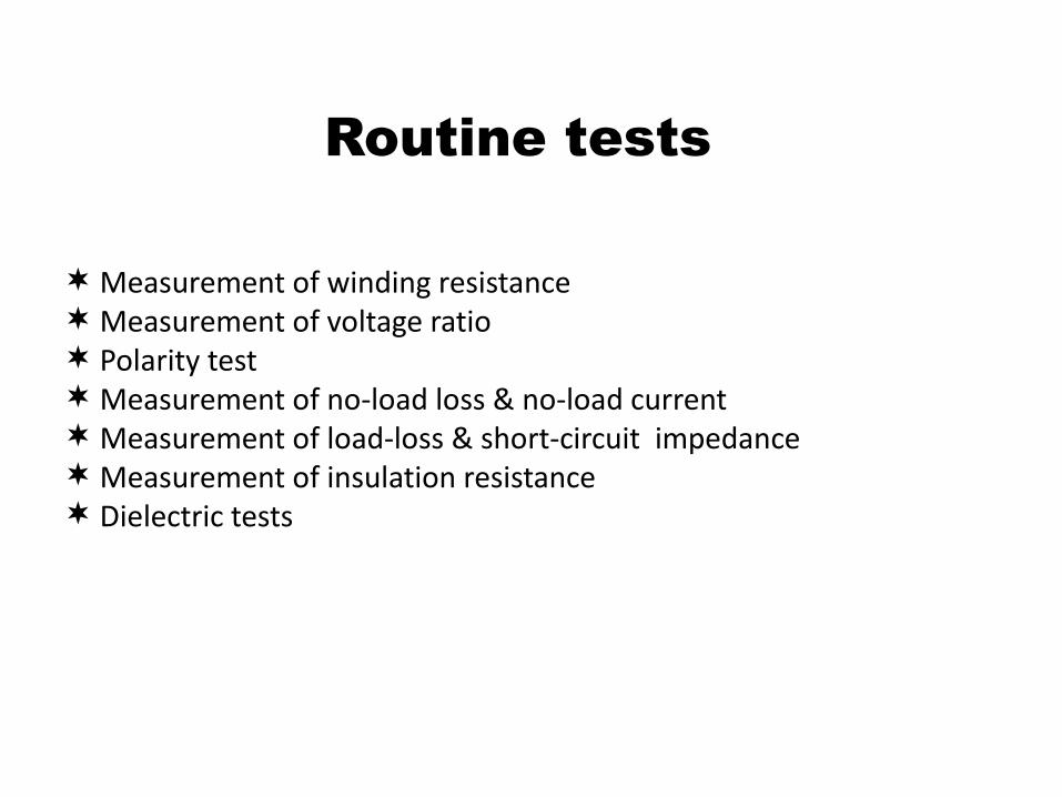
Measurement of winding resistance Measurement of voltage ratio Polarity test Measurement of no-load loss & no-load current Measurement of load-loss & short-circuit impedance Measurement of insulation resistance Dielectric tests
Routine tests

Measurement of winding resistance Measurement of voltage ratio Polarity test Measurement of no-load loss & no-load current Measurement of load-loss & short-circuit impedance Measurement of insulation resistance Dielectric tests Temperature-rise test
Type tests

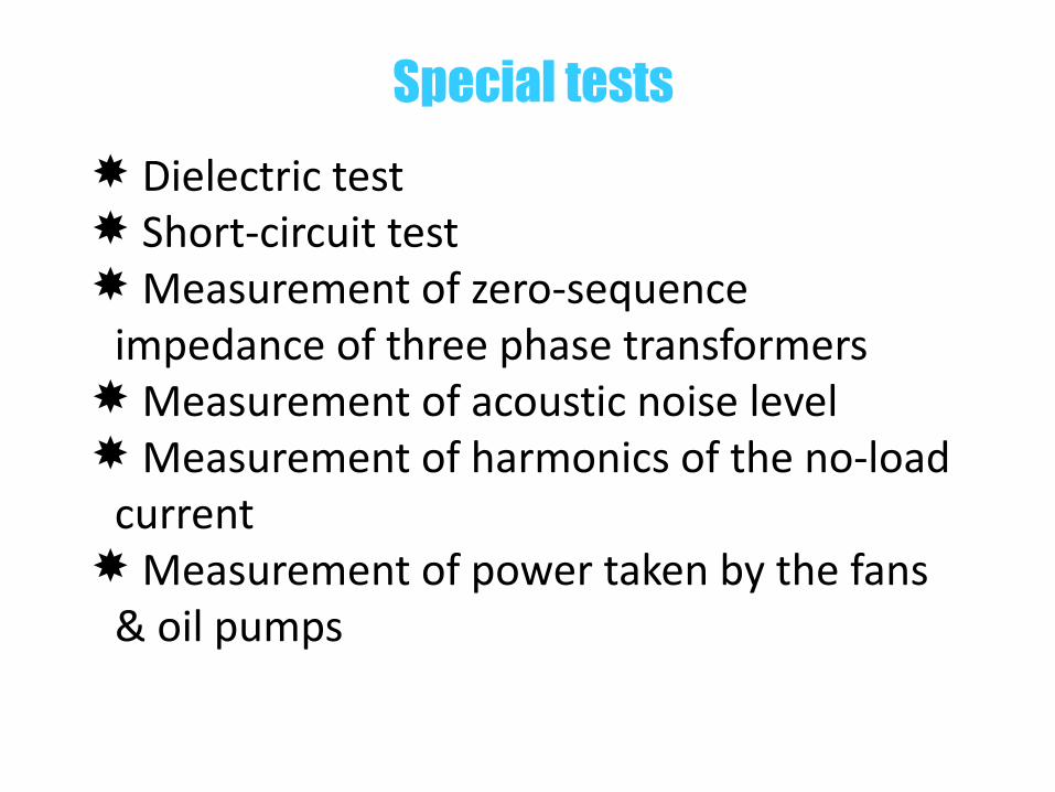
Dielectric test Short-circuit test Measurement of zero-sequence
impedance of three phase transformers Measurement of acoustic noise level Measurement of harmonics of the no-load
current Measurement of power taken by the fans
& oil pumps
Special tests
Dielectric test Short-circuit test Measurement of zero-sequence
impedance of three phase transformers Measurement of acoustic noise level Measurement of harmonics of the no-load
current Measurement of power taken by the fans
& oil pumps
Special tests
• Separate source voltage withstand test
• Induced over voltage withstand test
• Impulse voltage withstand test
Dielectric test
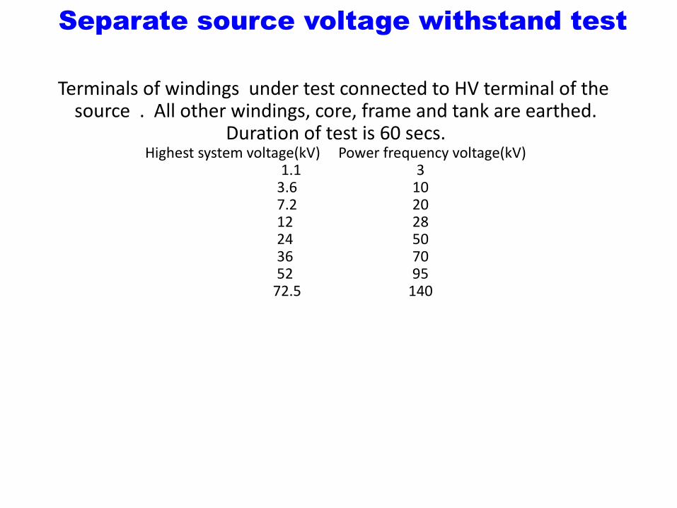
Terminals of windings under test connected to HV terminal of the source . All other windings, core, frame and tank are earthed.
Duration of test is 60 secs.Highest system voltage(kV) Power frequency voltage(kV)
1.1 33.6 107.2 2012 2824 5036 7052 95
72.5 140
Separate source voltage withstand test
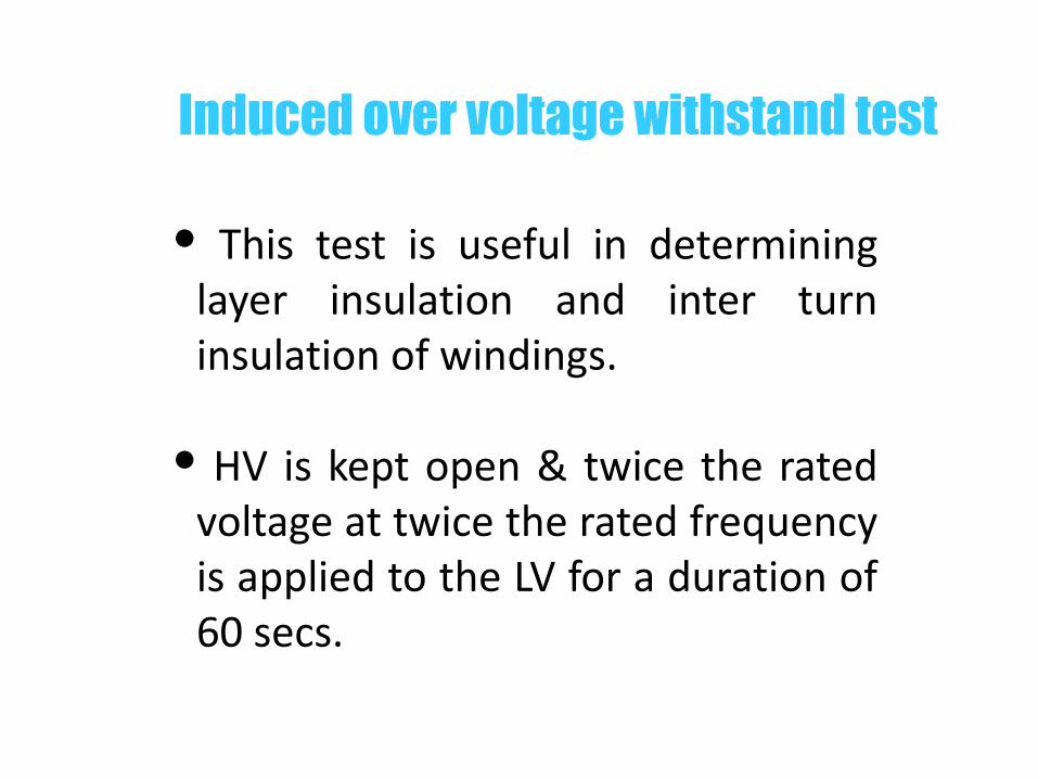
This test is useful in determining layer insulation and inter turn insulation of windings.
HV is kept open & twice the rated voltage at twice the rated frequency is applied to the LV for a duration of 60 secs.
Induced over voltage withstand test
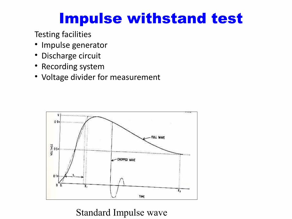
Testing facilities • Impulse generator• Discharge circuit• Recording system• Voltage divider for measurement
Standard Impulse wave
Impulse withstand test
Wave shape Standard wave shape of impulse voltage is
1.2/50µsec. t1 is the rise time = 1.2µsecs. t2 is the tail time = 50 µ secs. Tolerance on t1 is ±30% & ±20% on t2.
Impulse generator Impulse wave is generated by discharge of
capacitors charged in parallel into a wave shaping circuit.
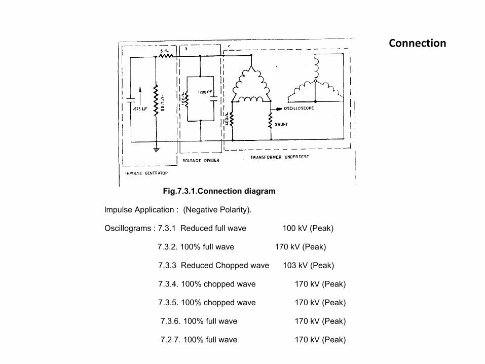
Connection
Fig.7.3.1.Connection diagram
lmpulse Application : (Negative Polarity).
Oscillograms : 7.3.1 Reduced full wave 100 kV (Peak)
7.3.2. 100% full wave 170 kV (Peak)
7.3.3 Reduced Chopped wave 103 kV (Peak)
7.3.4. 100% chopped wave 170 kV (Peak)
7.3.5. 100% chopped wave 170 kV (Peak)
7.3.6. 100% full wave 170 kV (Peak)
7.2.7. 100% full wave 170 kV (Peak)

Oscilograms

Oscilograms contd.
Oscilograms contd.
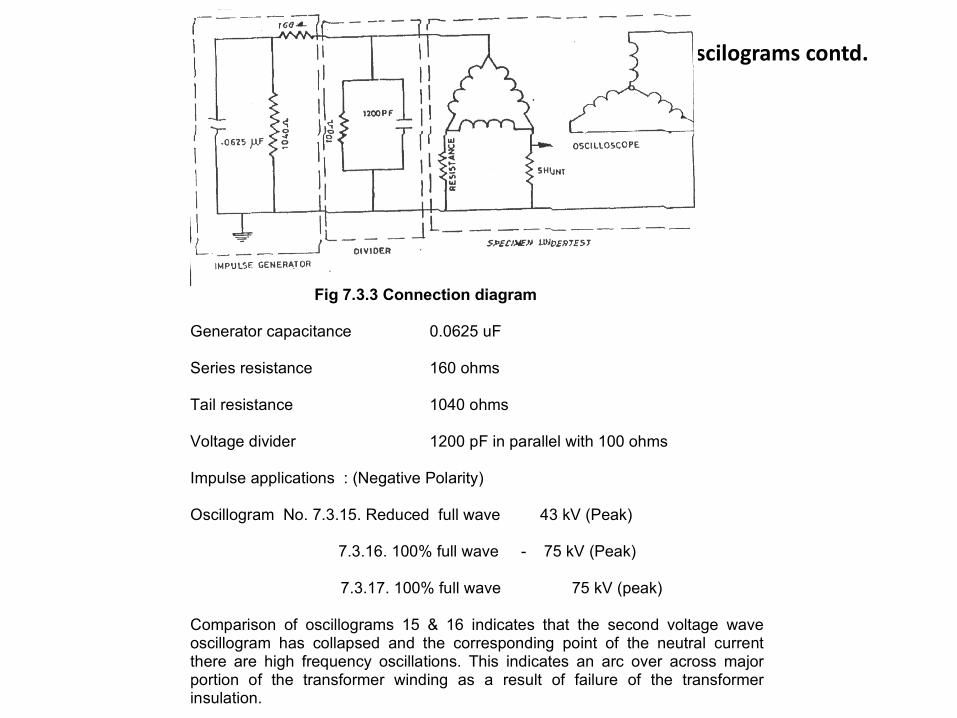
Fig 7.3.3 Connection diagram
Generator capacitance 0.0625 uF
Series resistance 160 ohms
Tail resistance 1040 ohms
Voltage divider 1200 pF in parallel with 100 ohms
Impulse applications : (Negative Polarity)
Oscillogram No. 7.3.15. Reduced full wave 43 kV (Peak)
7.3.16. 100% full wave - 75 kV (Peak)
7.3.17. 100% full wave 75 kV (peak)
Comparison of oscillograms 15 & 16 indicates that the second voltage waveoscillogram has collapsed and the corresponding point of the neutral currentthere are high frequency oscillations. This indicates an arc over across majorportion of the transformer winding as a result of failure of the transformerinsulation.
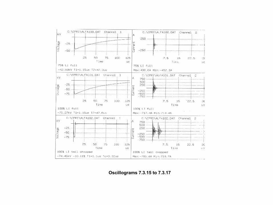
Oscillograms 7.3.15 to 7.3.17

MINOR INSULATION -conductor turns, layers ● enamel, paper ● oil ducts, paper cylinders
MAJOR INSULATION- winding, core ● press board cylinders, oil ducts
BUSHINGS - porcelain , condenser

Power & distribution transformers must be constructed to withstand mechanical stresses caused by external faults. These stresses are produced due to electromagnetic forces as a result of very high current in the windings during short-circuits.
Short-circuit test

Prior to the short-circuit, transformer is subjected to routine tests.
Asymmetrical current The peak current that transformer is
required to withstand = Isc(peak)=K Isc
Dynamic ability to withstand short-circuit
Value of K :x/r 1 1.5 2 3 4 5 6 8 10 >14
K 1.51 1.64 1.76 1.95 2.09 2.19 2.27 2.38 2.46 2.55
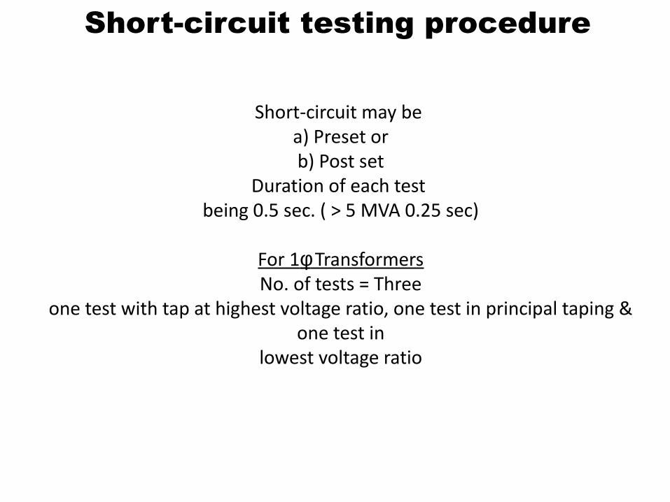
Short-circuit may be a) Preset orb) Post set
Duration of each test being 0.5 sec. ( > 5 MVA 0.25 sec)
For 1φ TransformersNo. of tests = Three
one test with tap at highest voltage ratio, one test in principal taping & one test in
lowest voltage ratio
Short-circuit testing procedure
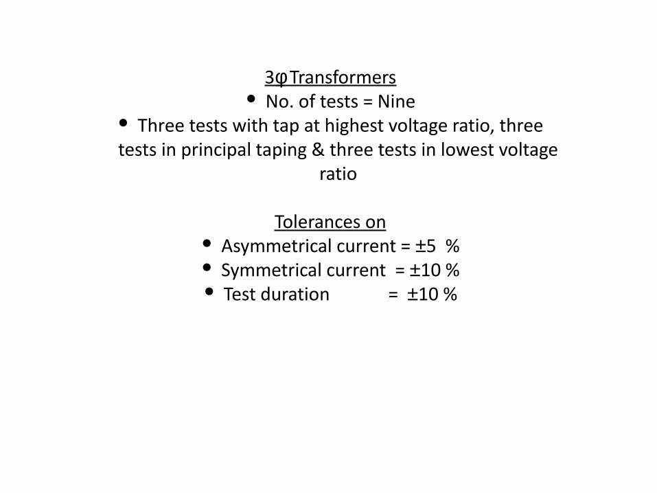
3φ Transformers No. of tests = Nine
Three tests with tap at highest voltage ratio, three tests in principal taping & three tests in lowest voltage
ratio
Tolerances on Asymmetrical current = ±5 % Symmetrical current = ±10 % Test duration = ±10 %
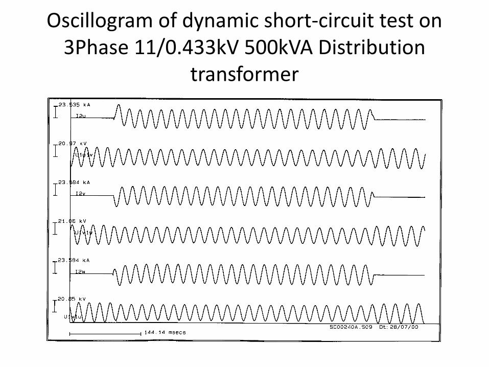
Oscillogram of dynamic short-circuit test on 3Phase 11/0.433kV 500kVA Distribution
transformer
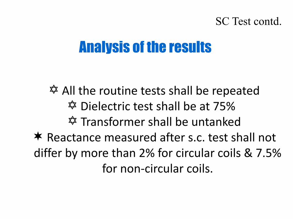
All the routine tests shall be repeated Dielectric test shall be at 75% Transformer shall be untanked
Reactance measured after s.c. test shall not differ by more than 2% for circular coils & 7.5%
for non-circular coils.
Analysis of the results
SC Test contd.
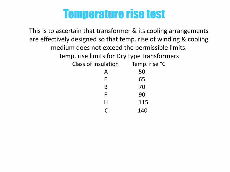
This is to ascertain that transformer & its cooling arrangements are effectively designed so that temp. rise of winding & cooling
medium does not exceed the permissible limits.Temp. rise limits for Dry type transformers
Class of insulation Temp. rise °CA 50E 65B 70F 90
H 115 C 140
Temperature rise test
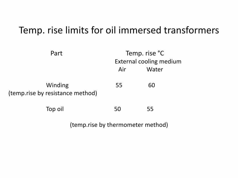
Temp. rise limits for oil immersed transformers
Part Temp. rise °C External cooling medium
Air Water
Winding 55 60 (temp.rise by resistance method)
Top oil 50 55
(temp.rise by thermometer method)
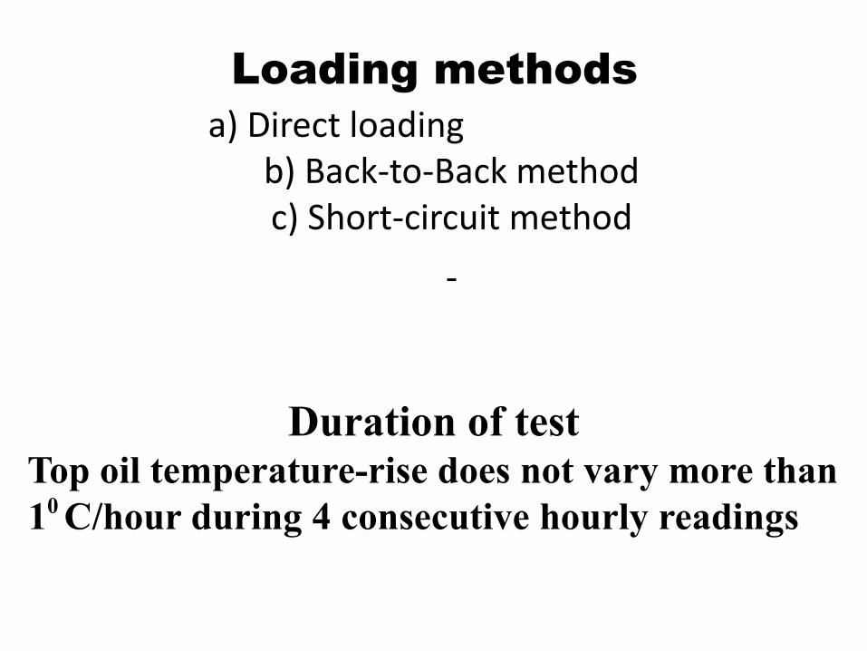
a) Direct loadingb) Back-to-Back methodc) Short-circuit method
Loading methods
Duration of test Top oil temperature-rise does not vary more than 10 C/hour during 4 consecutive hourly readings
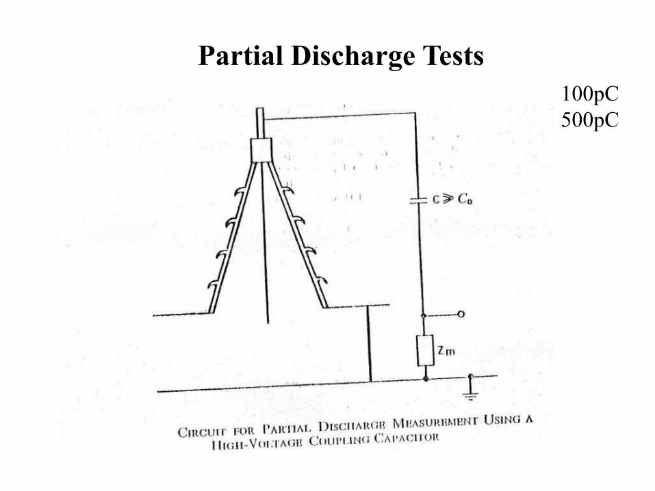
Partial Discharge Tests100pC500pC
Sound pressure level 20 log10 d/0.00002 dB
d Newton per square meter
Noise Level

meter

Highest voltagefor equipment
UmkV
(r.m.s. value)
Rated short durationpower frequencywithstand voltage
kV(r.m.s. value)
Ratedlightning impulsewithstand voltage
kV(peak value)
3.6 10 2040
7.2 20 4060
12 28 607595
17.5 38 7595
24 50 95125145
36 70 145170
52 95 250
72.5 140 325
123 (185)230
450550
145 (185)230275
(450)550650
170 (230)275325
(550)650750
245 (275)(325)360395460
(650)(750)850950
1050

Highestvoltage forequipment
Um kV
(r.m.s. value)
Standard switching impulse withstand voltage---------------------------------------------------------Longitudinal Phase-to-earth Phase-to-phaseInsulation (ratio to the (note 1) phase-to-earthkV kV peak value)(peak value) (peak value)
Standard lightning impulsewithstand voltage
kV(peak value)
300 750 750 1,50 850950
750 850 1,50 9501050
362 850 850 1,50 9501050
850 950 1,50 10501175
420 850 850 1,60 10501175
950 950 1,50 11751300
950 1050 1,50 13001425
525 950 950 1,70 11751300
950 1050 1,60 13001425
950 1175 1,50 14251550
765 1175 1300 1,70 16751800
1175 1425 1,70 18001950
1175 1550 1,60 19502100