Embed Size (px)
Citation preview
8/20/2019 SubstationCommissioning- Transformer Testing
http://slidepdf.com/reader/full/substationcommissioning-transformer-testing 1/83
8. TESTING POWER TRANSFORMERS
High-voltage transformers are some of the most important (and expensive) pieces ofequipment required for operating a power system. The purchase, preparation, assembly,
operation and maintenance of transformers represent a large expense to the powersystem.
8.1 OVERVIEW
When transformers are received from the factory or reallocated from another location it is
necessary to verify that each transformer is dry, no damage has occurred during shipping,
internal connections have not been loosened, the transformer’s ratio, polarity, and
impedance agree with its nameplate, its major insulation structure is intact, wiringinsulation has not been bridged, and the transformer is ready for service.
Physical size, voltage class, and kVA rating are the major factors that dictate the amountof preparation required to put transformers in service. Size and kVA rating also dictate
the kind and number of auxiliary devices a transformer will require. All of these factors
affect the amount of testing necessary to certify that a transformer is ready to beenergized and placed in service.
There are a multitude of checks and tests performed as a transformer is being assembled
at a substation. The test engineer may not directly perform all of the following tests andinspections but must be sure they are satisfactorily completed, so that the final decision
over transformer bank readiness for energization can be made.
Some tests and procedures may be performed by specialists during the assembly phase.Special tests, other than those listed, may also be required. Many require special
equipment and expertise that construction electricians do not have and are not expected to provide. Some tests are performed by an assembly crew, while other tests are done by
the person(s) making the final electrical tests on the transformers.
BPA has hundreds of power transformers installed throughout the system, and few ofthem are identical. The following information is not intended to describe, or include, the
details for performing the entire array of tests needed to prepare transformers for service,
only the tests that may be performed by field personnel. Even though details have beenlimited, descriptions should allow field personnel to perform, or assist in performing, the
basic tests they may be asked to do. Procedures and tests are described somewhat
generically, but apply to most transformers in one way or another. Also, the followingtest descriptions provide an anchor point from which to ask for help when needed. The
following items are discussed or described:
Nameplate Data Power Meggering
Auxiliary Components and Wire Checks Lightning Arrestors
Hand Meggering Temperature Devices
8/20/2019 SubstationCommissioning- Transformer Testing
http://slidepdf.com/reader/full/substationcommissioning-transformer-testing 2/83
CT Tests Winding Temperature and Thermal Image
Bushing Power Factoring Remote Temperature Indication
Transformer Power Factoring Auxiliary Power
Voltage Ratio Automatic Transfer Switch
Polarity Cooling System
Transformer-Turns Ratio Bushing Potential Device
Tap Changers Auxiliary-Equipment Protection and Alarms
Short-Circuit Impedance Overall Loading
Zero Sequence Trip Checks
Winding Resistance
Before proceding with transformer measurements the test engineer will become familiar
with the safety rules of Section 2. THESE RULES MUST BE FOLLOWED FOR
ALL TEST PROCEDURES. Following is an approximate sequence for transformer
testing:
1. Inspect transformer and parts for shipping damage and moisture.2. Check nameplate and prints for proper voltages and external phasing
connection to the line or bus.3. Check calibration of all thermal gauges and hot-spot heater, bridge RTDs and
associated alarm contacts. Contact settings should be similar to the following:
One stage runs all the time (forced cooling)
2nd stage at 80°C
3rd stage at 90°C
Hot-spot alarm 100°C (trip at 110°C when applicable)
Top-oil alarm 80°C at 55°C rise and 75°C at 65°C rise
OA = no fans or pumps
FA =fans running
FOA = fans and pumps running
4. Check and Megger all wiring point to point: Fans, pumps, alarms, heaters, tapchangers, and all other devices on the transformer and interconnecting cables
5. All banks above 150 MVA should be vacuum dried. Do not apply test voltages
to the winding during the vacuum drying process. Make certain the terminalsare shorted and grounded during oil circulation because of the large amount of
static charge that can build up on the winding.
6. After the tank has been filled with oil, confirm that an oil sample was sent tothe Chemical Lab and that its results are entered in the bank test reports. Notethe oil level and temperature at completion of filling.
7. Power operate to verify proper rotation of pumps and fans and correct
operation of the under load (UL) tap changer, when provided. Also, checkheater, alarms and all other devices for proper operation.
12. Following are the winding tests to be performed:
8/20/2019 SubstationCommissioning- Transformer Testing
http://slidepdf.com/reader/full/substationcommissioning-transformer-testing 3/83
Ratio and Polarity (Voltage Method or TTR). The preference is that all large
power Transformers (>1 MVA) be tested with TTR test set.
Impedance
DC winding resistance
Megger and Power Factor windings, bushing and arrestors. Note: Wait until 24hours after completion of oil filling for Power Factor testing.
13. Load CT circuits overall and flash for polarity.14. Before energization, trip-check bank protection schemes and make sure the gas-
collection relay is free of gas.
15. When energizing a bank or picking up load, monitor bank currents and voltages,
including UL tap-changer operation.16. Check proper phasing and voltage of the bank to the system before load is
picked up. When possible, large transformers (>1 MVA) should remain
energized for eight hours before carrying load.
17. Make in-service checks on meters and relays.18. Release to Operations and report energization information to the TNE office.
19. Turn in revised prints and test reports, which should include the following:
All test data
Moisture and oil data
Problems incurred
In-service data
Time energized and release to operation
Any unusual problem that information will aid in future equipment testing
8.2 NAMEPLATE DATA and TERMINAL MARKINGS
Collecting nameplate data is not testing, but it must be done for all equipment. This
data is recorded by the person(s) performing the equipment tests. The act of recording
the nameplate data also helps test personnel familiarize themselves with the unit to be
tested.
For a transformer, much of the needed information can be obtained from the main
nameplate. If there is an under load tap changer, it too will have a nameplate. CTs havename plates and may have them on the bushing pockets where they are mounted with
additional information on a nameplate placed inside the cooler-control cabinet door
(typical on large transformers). Bushings, fuses, fan and pump motors, lightningarrestors, and disconnect switches will also have individual nameplates. An attempt
should be made to fill in all pertinent spaces on the data sheet. A miscellaneous
information space is provided on data sheets for information that pertains to thetransformer but does not have a specified place to record it. Recording miscellaneous
information not identified specifically by a test data sheet may be important as well.
8/20/2019 SubstationCommissioning- Transformer Testing
http://slidepdf.com/reader/full/substationcommissioning-transformer-testing 4/83
Terminal marking of power transformers is determined by ANSI standards. Two-
winding transformers have terminals designated by H and X (e.g. H1, H
2, X
1, X
2,), where
H is the higher voltage-rated winding and X is the lower voltage winding. As viewedfrom the high-voltage side, H
1 bushing terminal will be located on the right. Three-or-
more-winding transformers will have winding designation H, X, Y and Z, where H is the
high-voltage winding (or, the highest kVA-rated winding in case windings have the samevoltage rating) and X, Y, and Z are for decreasing winding voltage ratings.
8.3 AUXILIARY COMPONENTS AND WIRE CHECKING
The size, type, and location of a transformer dictate the amount of external equipment
associated with it. A transformer may be outfitted with devices that are not to be used at
the time of installation. Even if not expected to be placed in service, all auxiliaryequipment should be checked for proper operation to assure it is not defective and could
be utilized in the future if needed. This is especially true for a new transformer, in order
to verify that what has been received is fully functional.
All wiring on the transformer should be checked and verified prior to energization.
Check control panels, terminal cabinets, and cables routed to the transformer. Torque all
screw, nut, and bolt terminals for tightness, including the wires on CTs where theyoriginate at the connection boxes on the high-voltage bushings. If there is an UL tap
changer, its wiring must also be checked.
Wire checking a transformer’s auxiliary equipment is useful for several reasons. A
thorough check might prevent damage or destruction of a unit that is difficult, expensive,
or impossible to replace. This process also provides personnel an opportunity to becomefamiliar with the equipment. A thorough wiring check forces personnel to look at the
equipment in detail, serves as a cross check for drawings, and verifies that documentationand prints actually represent the physical equipment. It helps assure that wires and
components are properly sized, secure, and ready for service.
8.4 HAND MEGGERING (DC Hi-Potential Insulation Testing)
Most hand-crank Meggers have output voltages from 250 to 500 volts DC. All wiring on
transformers should be Meggered at 250 or 500 VDC.
Meggering transformer wiring is emphasized because of the numerous small terminal
boxes mounted on large power transformers. Conduit connecting them together can havemoisture accumulation or water leaks. In addition, when wiring is pulled through themetal conduit on a transformer, occasionally the insulation is scraped down to the bare
wire.
Also note that any box mounted on a vertical surface should have a small drain hole
drilled at the bottom in case water leaks in from a loose conduit joint. Larger boxes or
cabinets usually have resistive heaters and air-vent holes covered by screens to prevent
8/20/2019 SubstationCommissioning- Transformer Testing
http://slidepdf.com/reader/full/substationcommissioning-transformer-testing 5/83
moisture accumulation. Terminal boxes mounted on horizontal surfaces must have good
weather seals for their covers. Any gasket with questionable ability to provide awatertight seal should be replaced.
Early completion of wire checking and low-voltage-component meggering is advisable,
especially when large transformers are to be tested. Completion of these tasks up front isimportant because it allows application of power to alarm and control circuits without
worry of causing damage. Having auxiliary power available helps facilitate operational
checks, especially when UL tap changers need to be operated to perform various tests.Changing tap positions manually by hand cranking the mechanism is a slow and tiresome
process.
8.5 CT TESTS
Transformer bushing CTs should be tested using the Current Ratio test method before the
transformer has been completely assembled. CTs should be tested before they are
mounted on the transformer. In some cases, CTs may have to be tested by connectingtest leads to both ends of an installed bushing. This can be difficult! If the CTs are
already mounted in the transformer, large (high-capacity) current-testing leads can be pulled through the CT centers before bushings have been inserted.
Occasionally it is not possible to perform a Current Ratio test. CT tap ratios can be
verified by applying a voltage across the full CT winding – a Tap Voltage Ratio test --then measuring the voltage drop across each individual tap. This is a simple test to
perform, and voltage ratios will be directly proportional to the CT turns ratio between
taps.
This Tap Voltage Ratio test, however, should not be chosen as a substitute for a CurrentRatio test. The voltage method should be regarded as the last alternative. Testing the
equipment at rated current offers more assurance that it will perform as expected when
placed in service. The Current Ratio method reflects this philosophy; the Tap VoltageRatio method does not. The Tap Voltage method cannot establish true orientation
(polarity) of the installed CT, or test the primary to secondary current ratio, and leaves
some points unverified.
In addition to Tap Voltage Ratio, a secondary Tap Current Ratio test can be performed.
For this test, rated or less current is injected through a tap input and the output current of
the full CT winding is measured by transformer action. It is equivalent to the procedure
used for performing a Short-Circuit Impedance test on an autotransformer.
CT POLARITY
It is still necessary to verify CT polarity. One method used to establish CT polarity in
power transformers is commonly referred to as "Flashing the CTs." This test can be performed by applying 6-to-12 volts DC to the transformer bushings, using a hot stick to
make and break the test circuit. An automobile battery is often most convenient because
8/20/2019 SubstationCommissioning- Transformer Testing
http://slidepdf.com/reader/full/substationcommissioning-transformer-testing 6/83
work vehicles are usually available at the job site, but a lantern battery will work as well.
The transformer winding resistance is usually enough to limit the current flow from a 12-volt car battery, but adding series (current-limiting) resistance (a load box) to the test
circuit is advisable in any test circuit with an automotive battery.
Be aware that the DC test circuit will generate a voltage kick when disconnected. Take precautions to prevent electric shock. If performing this test directly on CTs, always
include a current-limiting resistance (a load box) in the flash lead connections. Lantern
batteries have high internal resistance and don’t need an extra series resistor. Arc flash ona power transformer can be limited if the transformer windings are short circuited on the
side opposite those being flashed through.
WARNING!
A transformer winding that is carrying DC current will generate a large voltage
across the winding when disconnected. To prevent electric shock, use a means of
insulation from the connection when breaking the test connection. A hot-stick tool
is recommended.
WARNING!
When using lead-acid car batteries never make or break circuit connections on a
battery terminal. Lead-acid batteries produce hydrogen gas when charging and
have been known to explode if ignited by an electric spark when connecting directly
to both battery terminals.
To make a test circuit for flashing a CT, connect battery positive (the positive terminal ofa car battery) to the polarity end, or high-voltage terminal, of the transformer. Add series
resistance, such as a resistive load box, into the test circuit to limit short-circuit current.Current-limiting the short-circuit DC test current can reduce core magnetization.
Connect battery negative (car chassis or frame ground) to the test lead used with a hot-stick tool. The hot-stick lead is used to touch the nonpolarity end of the bushing or
station ground if a grounded transformer is being tested. Current must be allowed to flow
through the bushings and CTs long enough to build up a charge in the transformer
windings. A hot stick is required to make and break this charging path because anextremely large arc can be generated as the magnetic field collapses. An analog
voltmeter (such as a Simpson VOM) is connected across the CT secondary terminals with
the meter polarity side referenced to CT polarity (X1). While this charge and dischargeof the windings is initiated, an observer can also watch for buildup and collapse of the CT
secondary current on a low-scale ammeter plugged into an appropriate set of relays or
ammeters. The test meters deflect upscale on charge and downscale on discharge, if theCT polarity is correct. Begin the test by momentarily touching the bushing cap (or
ground connection) with battery negative for one or two seconds. Increase the DC
application time as needed to get enough meter deflection to assure results. If thetransformer requires some time to build a charge in its windings, there may not be very
much positive deflection on contact, whereas there may be a much greater negative
deflection on break.
8/20/2019 SubstationCommissioning- Transformer Testing
http://slidepdf.com/reader/full/substationcommissioning-transformer-testing 7/83
For CT accuracy and performance, flashing may not be a desirable test to perform because a condition of residual magnetism in the CT core can result. In theory, a possible
consequence could be an improper relay operation due to CT saturation upon initial
energization. If possible, demagnetizing the core is advisable after a DC flash test using
high current. Residual flux is removed by gradually applying AC test current (excitationcurrent) to the high-current primary, or AC test voltage to the low-current secondary
(excitation voltage), and forcing the CT just into saturation with the secondary open
circuited. After slowly reducing the AC quantity from saturation point to zero, residualflux will be removed from the core (it will be demagnetized).
8.6 BUSHING POWER FACTORING (AC Hi-Potential Insulation Testing)
All bushings should be power factored before they are inserted into the transformer. If a
Power Factor set is not available when a new transformer is being assembled, a
capacitance bridge should, at the very least, be used to measure the bushing tapcapacitance values. Measure the values for both C1 and C2 (especially if they are
specified on the bushing nameplate). A proper capacitance test could indicate whether aserious internal problem with a bushing exists prior to insertion and whether a power
factor test would be advisable.
Megger the bushing and its tap at 2500 volts if no Power Factor set is available.
CAUTION! Check the bushing tap insulation rating before applying 2500 volts; small bushings may be able to withstand no more than 500 or 1000 volts at the tap.
8.7 TRANSFORMER POWER FACTORING (AC Hi-Potential Insulation
Testing)
The transformer itself should be power factored soon after the drying process is complete
and the tank is filled with oil. All bushings should again be power factored at this time
because their readings will change slightly after assembly. A complete set of Power
Factor data should include winding-to-winding, winding-to-ground, and bushing tests. Ifa 10-kV power factor set is available, a Winding Excitation test should be performed. A
Winding Excitation test on very large transformers may not be possible due toinsufficient capacity of the Power Factor set for supplying required excitation current.
8.8 SINGLE-PHASE VOLTAGE RATIO, POLARITY and IMPEDANCE
MEASUREMENTS
Ratio, polarity, and impedance measurements are compared with nameplate data to verify
their correctness and to ensure that there is no hidden shipping damage, that the
8/20/2019 SubstationCommissioning- Transformer Testing
http://slidepdf.com/reader/full/substationcommissioning-transformer-testing 8/83
transformer field assembly is correct, and that the transformer is ready for service. In
addition, these test data reports become a valuable tool when compared with laterdiagnostic tests used to assess transformer condition.
Single-phase test procedures can be used to measure the ratio and impedance of
two-winding transformers, three-winding transformers, autotransformers, andthree-phase transformers. Moreover, in the case of three-phase transformers (with a
Wye connection) and grounding banks, zero-sequence impedance measurements are
made with the single-phase procedure. Comparisons between measurements are usefulwhen single-phase tests are made on three identical transformers or on each phase of a
three-phase transformer, as it is unlikely that each single-phase unit or each phase of a
three-phase transformer would have sustained the same damage.
Safety
Before proceeding with any measurements in a high-voltage substation, the test engineermust be thoroughly familiar with the job. Make sure the transformer bank being tested is
de-energized, out of service, and isolated from the power system before climbing on it orconnecting it to any test leads.
Follow all safety rules and be aware of any energized equipment in the working area.
Never uncoil test leads by throwing them in energized yards. Ground test equipment and
test circuits to avoid stray voltages from energized lines, lightning or close-in faults. Takecare to check the polarity of the test voltage. The grounded leg of the 115-VAC source
shall be connected to ground for safety.
WARNING!
Extreme caution must be observed when test-energizing high-ratio transformers (10
to 1, for example), because high voltages will be present at the transformer
terminals. Care must be taken not to energize bus or equipment that electricians or
other personnel could be working on and that test equipment does not contact
energized equipment.
If equipment terminals are accessible or if the bus is connected to the transformer
terminals, conceivably transferring test potentials to other locations, fence off theexposed areas with guards as required by safety procedures, warn working personnel of
test-energized potentials, and if necessary provide a Safety Watcher. If possible, ratio test
transformers before terminal connections to buses have been made.
8.8.1 SINGLE-PHASE POLARITY
The polarity designation of each transformer winding is determined by the relative
direction of instantaneous current or voltage as seen at the transformer terminals. For
example, primary and secondary leads are said to have the same polarity when, at a giveninstant, current enters the primary lead in question, the instantaneous induced voltage in
the secondary is increasing when the impressed voltage on the primary is increasing, or
conversely, if they are both decreasing at the same instant.
8/20/2019 SubstationCommissioning- Transformer Testing
http://slidepdf.com/reader/full/substationcommissioning-transformer-testing 9/83
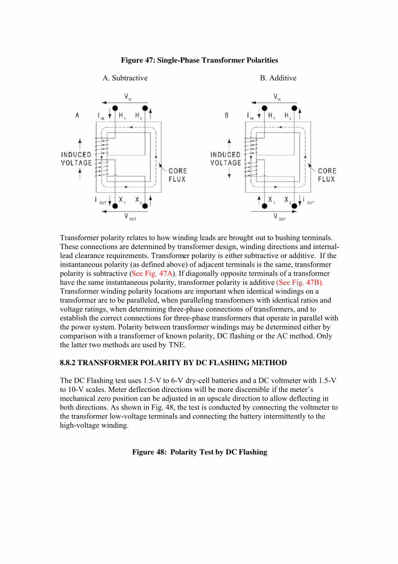
Figure 47: Single-Phase Transformer Polarities
A. Subtractive B. Additive
Transformer polarity relates to how winding leads are brought out to bushing terminals.
These connections are determined by transformer design, winding directions and internal-
lead clearance requirements. Transformer polarity is either subtractive or additive. If theinstantaneous polarity (as defined above) of adjacent terminals is the same, transformer
polarity is subtractive (See Fig. 47A). If diagonally opposite terminals of a transformer
have the same instantaneous polarity, transformer polarity is additive (See Fig. 47B).Transformer winding polarity locations are important when identical windings on a
transformer are to be paralleled, when paralleling transformers with identical ratios and
voltage ratings, when determining three-phase connections of transformers, and toestablish the correct connections for three-phase transformers that operate in parallel with
the power system. Polarity between transformer windings may be determined either by
comparison with a transformer of known polarity, DC flashing or the AC method. Onlythe latter two methods are used by TNE.
8.8.2 TRANSFORMER POLARITY BY DC FLASHING METHOD
The DC Flashing test uses 1.5-V to 6-V dry-cell batteries and a DC voltmeter with 1.5-V
to 10-V scales. Meter deflection directions will be more discernible if the meter’s
mechanical zero position can be adjusted in an upscale direction to allow deflecting in both directions. As shown in Fig. 48, the test is conducted by connecting the voltmeter to
the transformer low-voltage terminals and connecting the battery intermittently to the
high-voltage winding.
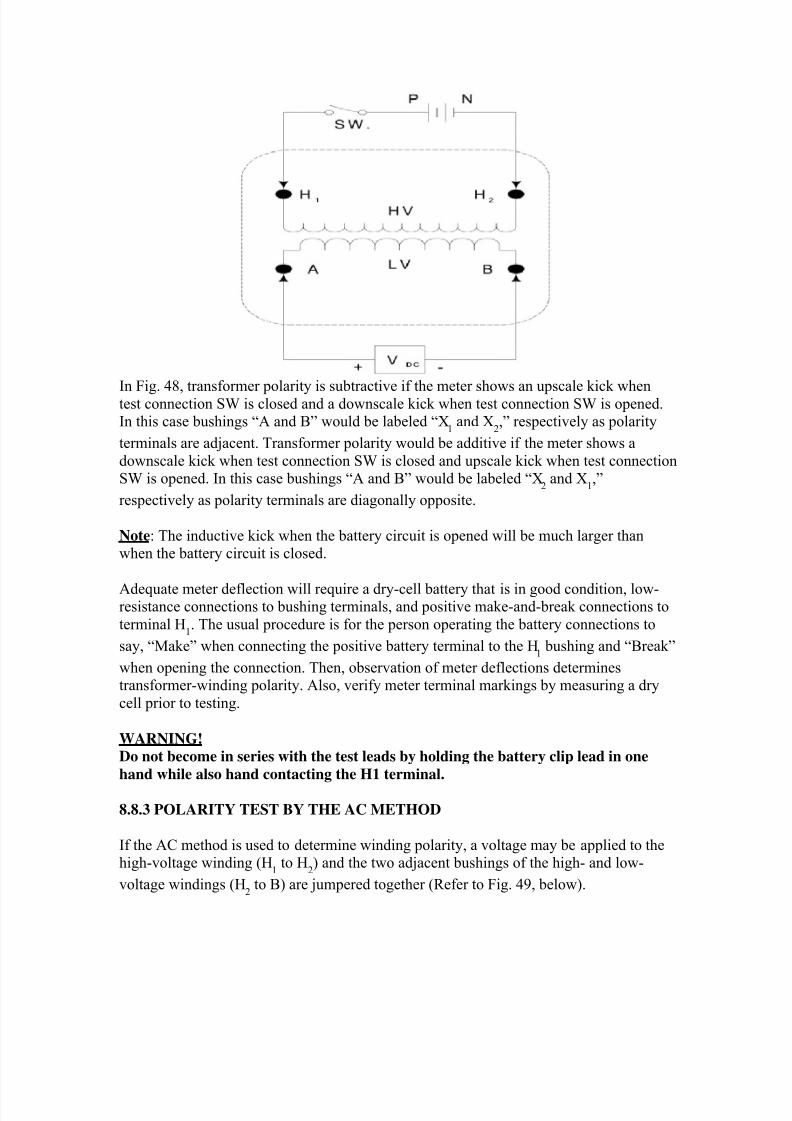
Figure 48: Polarity Test by DC Flashing
8/20/2019 SubstationCommissioning- Transformer Testing
http://slidepdf.com/reader/full/substationcommissioning-transformer-testing 10/83
In Fig. 48, transformer polarity is subtractive if the meter shows an upscale kick whentest connection SW is closed and a downscale kick when test connection SW is opened.In this case bushings “A and B” would be labeled “X
1 and X
2,” respectively as polarity
terminals are adjacent. Transformer polarity would be additive if the meter shows a
downscale kick when test connection SW is closed and upscale kick when test connectionSW is opened. In this case bushings “A and B” would be labeled “X
2 and X
1,”
respectively as polarity terminals are diagonally opposite.
Note: The inductive kick when the battery circuit is opened will be much larger thanwhen the battery circuit is closed.
Adequate meter deflection will require a dry-cell battery that is in good condition, low-resistance connections to bushing terminals, and positive make-and-break connections to
terminal H1. The usual procedure is for the person operating the battery connections to
say, “Make” when connecting the positive battery terminal to the H1 bushing and “Break”
when opening the connection. Then, observation of meter deflections determinestransformer-winding polarity. Also, verify meter terminal markings by measuring a dry
cell prior to testing.
WARNING!
Do not become in series with the test leads by holding the battery clip lead in one
hand while also hand contacting the H1 terminal.
8.8.3 POLARITY TEST BY THE AC METHOD
If the AC method is used to determine winding polarity, a voltage may be applied to thehigh-voltage winding (H
1 to H
2) and the two adjacent bushings of the high- and low-
voltage windings (H2 to B) are jumpered together (Refer to Fig. 49, below).
8/20/2019 SubstationCommissioning- Transformer Testing
http://slidepdf.com/reader/full/substationcommissioning-transformer-testing 11/83
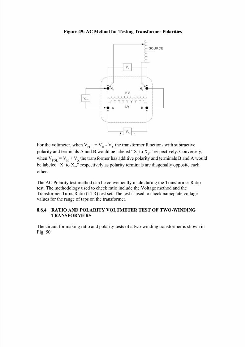
Figure 49: AC Method for Testing Transformer Polarities
For the voltmeter, when VPOL
= VH - V
X the transformer functions with subtractive
polarity and terminals A and B would be labeled “X1 to X
2,” respectively. Conversely,
when VPOL
= VH + V
Xthe transformer has additive polarity and terminals B and A would
be labeled “X1 to X
2,” respectively as polarity terminals are diagonally opposite each
other.
The AC Polarity test method can be conveniently made during the Transformer Ratiotest. The methodology used to check ratio include the Voltage method and the
Transformer Turns Ratio (TTR) test set. The test is used to check nameplate voltage
values for the range of taps on the transformer.
8.8.4 RATIO AND POLARITY VOLTMETER TEST OF TWO-WINDING
TRANSFORMERS
The circuit for making ratio and polarity tests of a two-winding transformer is shown in
Fig. 50.
8/20/2019 SubstationCommissioning- Transformer Testing
http://slidepdf.com/reader/full/substationcommissioning-transformer-testing 12/83
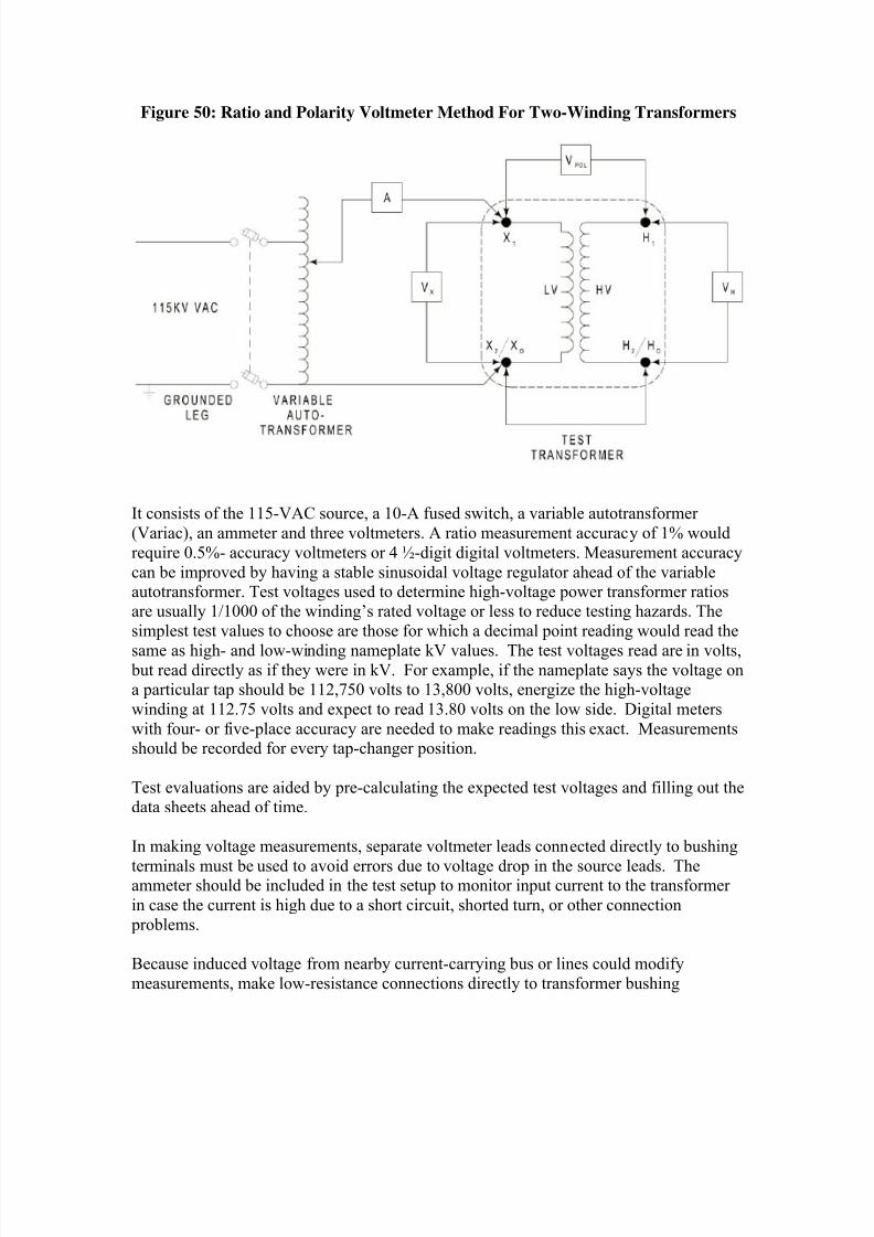
Figure 50: Ratio and Polarity Voltmeter Method For Two-Winding Transformers
It consists of the 115-VAC source, a 10-A fused switch, a variable autotransformer
(Variac), an ammeter and three voltmeters. A ratio measurement accuracy of 1% would
require 0.5%- accuracy voltmeters or 4 ½-digit digital voltmeters. Measurement accuracy
can be improved by having a stable sinusoidal voltage regulator ahead of the variableautotransformer. Test voltages used to determine high-voltage power transformer ratiosare usually 1/1000 of the winding’s rated voltage or less to reduce testing hazards. The
simplest test values to choose are those for which a decimal point reading would read the
same as high- and low-winding nameplate kV values. The test voltages read are in volts, but read directly as if they were in kV. For example, if the nameplate says the voltage ona particular tap should be 112,750 volts to 13,800 volts, energize the high-voltage
winding at 112.75 volts and expect to read 13.80 volts on the low side. Digital meters
with four- or five-place accuracy are needed to make readings this exact. Measurementsshould be recorded for every tap-changer position.
Test evaluations are aided by pre-calculating the expected test voltages and filling out thedata sheets ahead of time.
In making voltage measurements, separate voltmeter leads connected directly to bushing
terminals must be used to avoid errors due to voltage drop in the source leads. Theammeter should be included in the test setup to monitor input current to the transformer
in case the current is high due to a short circuit, shorted turn, or other connection
problems.
Because induced voltage from nearby current-carrying bus or lines could modify
measurements, make low-resistance connections directly to transformer bushing
8/20/2019 SubstationCommissioning- Transformer Testing
http://slidepdf.com/reader/full/substationcommissioning-transformer-testing 13/83
terminals and don’t coil up excess potential lead length; lay excessive leads side by side,
oriented at 90° with induction sources.
The lower voltage winding should be excited, in most cases, to some multiple of its
rating. For example, if the transformer in Fig. 50 is rated 115.5 kV to 7.2 kV, energize the
low-voltage winding to 7.2 V, then measure voltage on the high-voltage winding. Thehigh side should be 1/1000 of its rating, or 115.5 V. The voltmeter, VPOL
, will read the
difference -- 108.3 V -- for subtractive transformers.
If the high side has a tap changer, hold the 7.2 V constant on the low-voltage winding and
read the new high-side voltage for each tap position. These voltages may be compared
directly with the nameplate values.
WARNING!
Remember, if transformer terminals are accessible or if bussing is connected to the
transformer terminals, all safety procedures of this transformer section as well as
Section 2 must be followed.
8.8.5 MEASUREMENTS FOR SINGLE-PHASE THREE-WINDING
TRANSFORMERS
Diagnostic tests of single-phase three-winding transformers are made with the procedures described above for single-phase two-winding transformers. Ratio, polarity
and impedance measurements are made between winding pairs, i.e., high-to-low-, high-
to-medium- and medium-to-low-voltage windings, as shown below (See Fig. 51).
8/20/2019 SubstationCommissioning- Transformer Testing
http://slidepdf.com/reader/full/substationcommissioning-transformer-testing 14/83
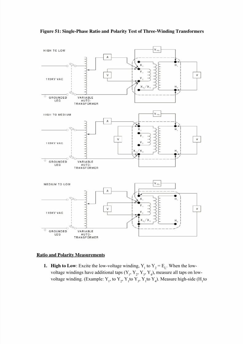
Figure 51: Single-Phase Ratio and Polarity Test of Three-Winding Transformers
Ratio and Polarity Measurements
1. High to Low: Excite the low-voltage winding, Y1 to Y
2 = E
L. When the low-
voltage windings have additional taps (Y1, Y
2, Y
3, Y
4), measure all taps on low-
voltage winding. (Example: Y1, to Y
2, Y
1to Y
3, Y
1to Y
4). Measure high-side (H
1to
8/20/2019 SubstationCommissioning- Transformer Testing
http://slidepdf.com/reader/full/substationcommissioning-transformer-testing 15/83
H0) voltage throughout its tap-changer range, E
H. Ratio = E
H/E
L.
2. Medium to Low: Excite low voltage winding, Y1to Y
2 = E
L. Measure medium
voltage, XH
to X2/X
0, throughout its tap-changer range, E
M. Ratio = E
M/E
L
3. High to Medium: Excite medium-voltage winding, X1to X
2/X
0= E
M. Set
medium winding on nominal tap, measure high-voltage winding, H1to H
2, E
H
throughout its tap-changer range, EH. Ratio = E
H/E
M. In case of auto banks, get
high winding on nominal and measure voltage throughout medium tap-changer
range.
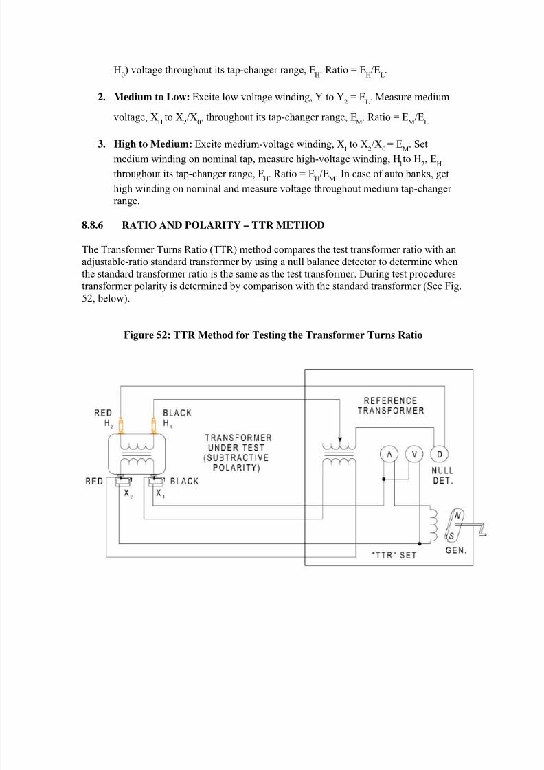
8.8.6 RATIO AND POLARITY – TTR METHOD
The Transformer Turns Ratio (TTR) method compares the test transformer ratio with an
adjustable-ratio standard transformer by using a null balance detector to determine whenthe standard transformer ratio is the same as the test transformer. During test procedures
transformer polarity is determined by comparison with the standard transformer (See Fig.
52, below).
Figure 52: TTR Method for Testing the Transformer Turns Ratio
8/20/2019 SubstationCommissioning- Transformer Testing
http://slidepdf.com/reader/full/substationcommissioning-transformer-testing 16/83
A TTR test should be made for any new high-voltage power transformer at the time it is
being installed. This test is also desirable for any transformer that has been overhauled orrelocated.
Note: TTR is the preferred ratio method as its accuracy is 0.1%. All maintenance districts
use the TTR data as a diagnostic base when performing transformer maintenance. TheVoltmeter method is also used because it is an excellent test for verifying the proper tap
changer make and break, and is easily converted to the impedance test setup that follows.
TTR Operation
Excitation current and voltage are supplied by two separate test lead pairs attached to thesecondary of the transformer, and a third pair of test leads monitors the primary voltage.
These quantities are fed into the test set null detector. As the hand-crank generator is
operated at moderate speed, the bridge-like TTR controls are manipulated to obtain a"null." The final balance point appears as a dial readout when the null is attained while
cranking out a steady eight-volt excitation level.
A relatively simple and straightforward description of how to connect and operate theTTR set can be found in a small instruction book usually stored inside the test lead
storage compartment. Brief operational instructions are also glued to the inside of the
test set lid. The instructions illustrate the test connections, etc. Winding connections mayhave to be swapped side for side on some transformers if excitation requirements are too
high.
The test set built-in hand-crank generator provides a repeatable, stable, sinusoidal test
voltage. Power system interference is minimized by the frequency of the generator and power systems. However, if the adjacent bay is energized or if there is an energized line
overhead, ground one bushing terminal of each test winding being measured and ground
the TTR tester with its ground terminal. Follow the manufacturer’s instructions for theuse of the TTR set and observe the following precautions:
Tap ratios should be pre-calculated so that test readings can be quickly evaluated. Data
sheets should be filled out as completely as possible ahead of time. The best place torecord the TTR test data is on the Power Transformer Test Record sheet, next to the
voltage ratio test readings. The advantage of recording TTR data on this sheet is that it
can be conveniently compared to the expected ratio values, which can be calculated fromthe recorded transformer nameplate data. Recording information in this manner serves to
keep similar types of data together and eliminates the need for another data sheet.
The TTR basically operates as a very accurate bridge (analogous to the Wheatstone
Bridge). Measurements are dependent on the winding ratio between the excited winding
and the measured winding. The test results are repeatable, a fact which makes dataobtained from this test significant. This data is most useful for analyzing transformer
problems where a shorted turn is suspected.
8/20/2019 SubstationCommissioning- Transformer Testing
http://slidepdf.com/reader/full/substationcommissioning-transformer-testing 17/83
CAUTION! Safety procedures of this transformer section and Section 2 must be followed. Disconnect
all transformer terminals from line or load. Neutrals directly grounded to the grid can
remain connected.
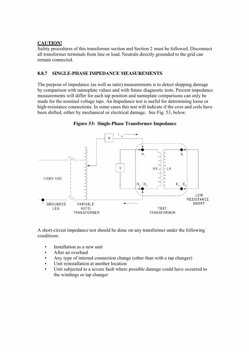
8.8.7 SINGLE-PHASE IMPEDANCE MEASUREMENTS
The purpose of impedance (as well as ratio) measurements is to detect shipping damage
by comparison with nameplate values and with future diagnostic tests. Percent impedance
measurements will differ for each tap position and nameplate comparisons can only be
made for the nominal voltage taps. An Impedance test is useful for determining loose orhigh-resistance connections. In some cases this test will indicate if the core and coils have
been shifted, either by mechanical or electrical damage. See Fig. 53, below.
Figure 53: Single-Phase Transformer Impedance
A short-circuit impedance test should be done on any transformer under the following
conditions:
• Installation as a new unit• After an overhaul• Any type of internal connection change (other than with a tap changer)
• Unit reinstallation at another location• Unit subjected to a severe fault where possible damage could have occurred to
the windings or tap changer
8/20/2019 SubstationCommissioning- Transformer Testing
http://slidepdf.com/reader/full/substationcommissioning-transformer-testing 18/83
Because of the wide linearity of power transformers, it is possible to measure these
parameters relative to rated frequency test voltages and test currents with magnitudes thatare only a very small fraction of rated values. The low-voltage source should be
sinusoidal (preferably regulated):
• Using input voltages greater than 7.0 V• Using rms-type voltmeters and ammeters
• Measuring voltages directly at transformer terminals
• Measuring ratio and impedance for each tap position.
Safety procedures discussed previously in this transformer section should be reviewed
before starting these tests.
An Impedance test is useful for determining loose or high-resistance connections. In
some cases this test will indicate if the core and coils have been shifted, either bymechanical or electrical damage.
The single-phase low-current measurement of winding impedance can be used for single- phase, three-phase and autotransformers by short circuiting one pair of terminals and
applying a voltage at rated frequency to the corresponding pair of terminals. If the test ismore than 5% off from nameplate data a more involved and accurate test is needed.
However, if comparisons between phases are within 2%, the test will be accurate. The
rated current and voltage used in percent impedance formulas are for the excited winding.
The circuit for measuring the impedance of a single-phase transformer is shown in Fig.
53. It consists of a fused switch, a variable autotransformer (Variac), an AC ammeter and
an AC voltmeter (preferably high impedance). To obtain 1% accuracy in the impedancecalculation the ammeter and voltmeter should have 0.5% accuracies or 4 1/2 digits with a
digital meter. Using a sinusoidal voltage regulator ahead of the variable autotransformerfacilitates accurate measurements. Input current to the test transformer must be
sinusoidal.
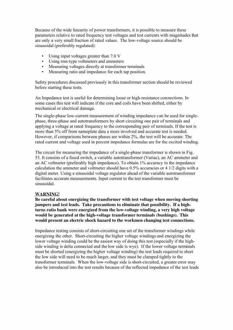
WARNING!
Be careful about energizing the transformer with test voltage when moving shorting
jumpers and test leads. Take precautions to eliminate that possibility. If a high-
turns ratio bank were energized from the low-voltage winding, a very high voltage
would be generated at the high-voltage transformer terminals (bushings). This
would present an electric shock hazard to the workmen changing test connections.
Impedance testing consists of short-circuiting one set of the transformer windings whileenergizing the other. Short-circuiting the higher voltage windings and energizing the
lower voltage winding could be the easiest way of doing this test (especially if the high-side winding is delta connected and the low side is wye). If the lower voltage terminals
must be shorted (energizing the higher voltage winding) the test leads required to short
the low side will need to be much larger, and they must be clamped tightly to thetransformer terminals. When the low-voltage side is short-circuited, a greater error may
also be introduced into the test results because of the reflected impedance of the test leads
8/20/2019 SubstationCommissioning- Transformer Testing
http://slidepdf.com/reader/full/substationcommissioning-transformer-testing 19/83
(see note, below). If doubt exists about which method is best (shorting the high side or
the low side), the test can be verified by taking measurements both ways and calculatingthe percent impedance using subsequent formulas (see below). The calculated value for
percent impedance will yield the same number regardless from which side of a
transformer the short-circuit impedance was measured.
Low-resistance test leads must be used for short-circuiting the winding. Accurate test
results will be assured if high ampacity test leads (2/0 or 4/0) are connected across the
terminals, especially if the low-voltage side is being shorted. They should have a cross-sectional area equal to or greater than the corresponding transformer leads, be kept as
short as possible, and make a clean, tight, low-resistance connection to the bushing
terminals. Using short, heavy wires will keep the reflected impedance very small, thusminimizing error. A high-resistance short will result in high measured impedance. The
applied voltage and input current are measured and impedance calculated by VM
/IM
.
Note: Any error created in readings by the added resistance from shorting leads of 2/0 or
4/0 copper cable does not warrant worrying about which side of a transformer to shortand in which side to inject test current. The resistance of 4/0 cable is approximately 0.05
ohms per 1000 ft. A 30-foot jumper would be only 0.0015 ohms. Even thirty feet of 1/0is only 0.003 ohms. For the leads typically used, they would introduce less than 0.5%
error in measurements taken on transformer windings of high-turns ratio (like on a 230-
kV wye to 13.8 kV delta or an H-to-X winding ratio of a 500-kV autotransformer bankwith a 34.5-kV delta tertiary). Lower ratios (like the 2:1 ratio of a 230/115-kV or 500/
230-kV transformer) would be typically less than 0.02 % (less than the accuracy of many
DMMs). Contact resistance is more likely a cause for error than shorting jumper
resistance. From a safety standpoint, it may be best to always apply test voltage andcurrent to the highest voltage winding. This would assure that no voltage higher than the
test voltage could be possible at any of the transformer terminals.
The same test setup and equipment can be used as for the Ratio test by applying an
appropriate short circuit and removing the jumper and extra voltmeters. This test is one ofthe most meaningful of the pre-energization tests on the transformer. It is used for future
reference if the bank fails, has several close-in faults or needs to be checked for other
reasons. The lab uses this data as a fingerprint relative to its present condition. Withaccurate data it is possible to determine if a transformer has a shorted turn, open winding
or internal movement.
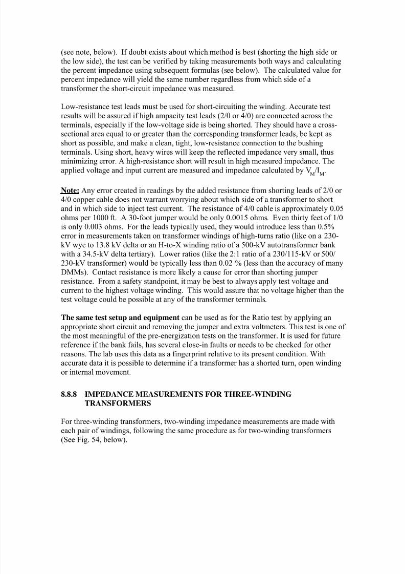
8.8.8 IMPEDANCE MEASUREMENTS FOR THREE-WINDING
TRANSFORMERS
For three-winding transformers, two-winding impedance measurements are made witheach pair of windings, following the same procedure as for two-winding transformers
(See Fig. 54, below).
8/20/2019 SubstationCommissioning- Transformer Testing
http://slidepdf.com/reader/full/substationcommissioning-transformer-testing 20/83
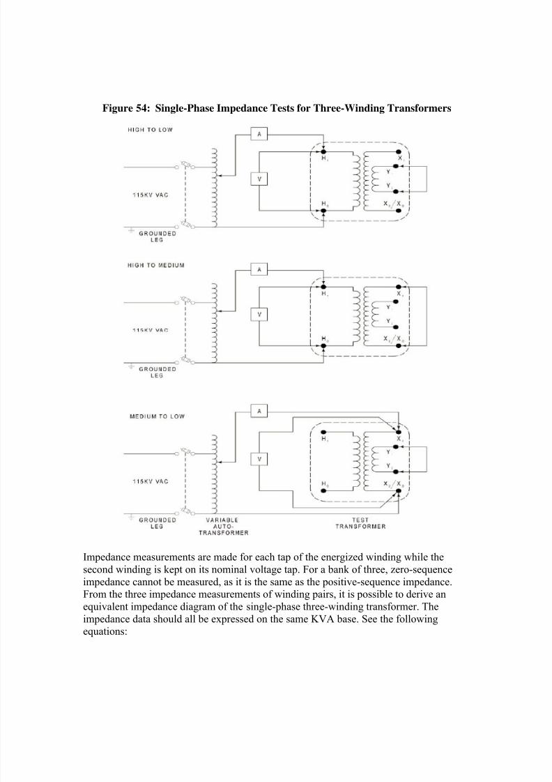
Figure 54: Single-Phase Impedance Tests for Three-Winding Transformers
Impedance measurements are made for each tap of the energized winding while the
second winding is kept on its nominal voltage tap. For a bank of three, zero-sequence
impedance cannot be measured, as it is the same as the positive-sequence impedance.From the three impedance measurements of winding pairs, it is possible to derive an
equivalent impedance diagram of the single-phase three-winding transformer. The
impedance data should all be expressed on the same KVA base. See the followingequations:
8/20/2019 SubstationCommissioning- Transformer Testing
http://slidepdf.com/reader/full/substationcommissioning-transformer-testing 21/83
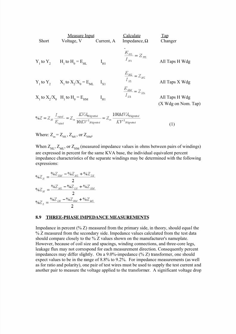
Measure Input Calculate TapShort Voltage, V Current, A Impedance,Ω Changer
Y1
to Y2 H
1to H
0 = E
HLIH1
All Taps H Wdg
Y1
to Y2 X
1to X
2/X
0 = E
MLI
X1All Taps X Wdg
X1
to X2/X
0 H
1to H
0 = E
HMI
H1All Taps H Wdg
(X Wdg on Nom. Tap)
(1)
Where: Zm
= ZHL
, ZML
, or ZHM
,
When ZHL
, ZML
, or ZHM
(measured impedance values in ohms between pairs of windings)
are expressed in percent for the same KVA base, the individual equivalent percentimpedance characteristics of the separate windings may be determined with the following
expressions:
8.9 THREE-PHASE IMPEDANCE MEASUREMENTS
Impedance in percent (% Z) measured from the primary side, in theory, should equal the
% Z measured from the secondary side. Impedance values calculated from the test datashould compare closely to the % Z values shown on the manufacturer's nameplate.
However, because of coil size and spacings, winding connections, and three-core legs,
leakage flux may not correspond for each measurement direction. Consequently percentimpedances may differ slightly. On a 9.0%-impedance (% Z) transformer, one should
expect values to be in the range of 8.8% to 9.2%. For impedance measurements (as well
as for ratio and polarity), one pair of test wires must be used to supply the test current andanother pair to measure the voltage applied to the transformer. A significant voltage drop
8/20/2019 SubstationCommissioning- Transformer Testing
http://slidepdf.com/reader/full/substationcommissioning-transformer-testing 22/83
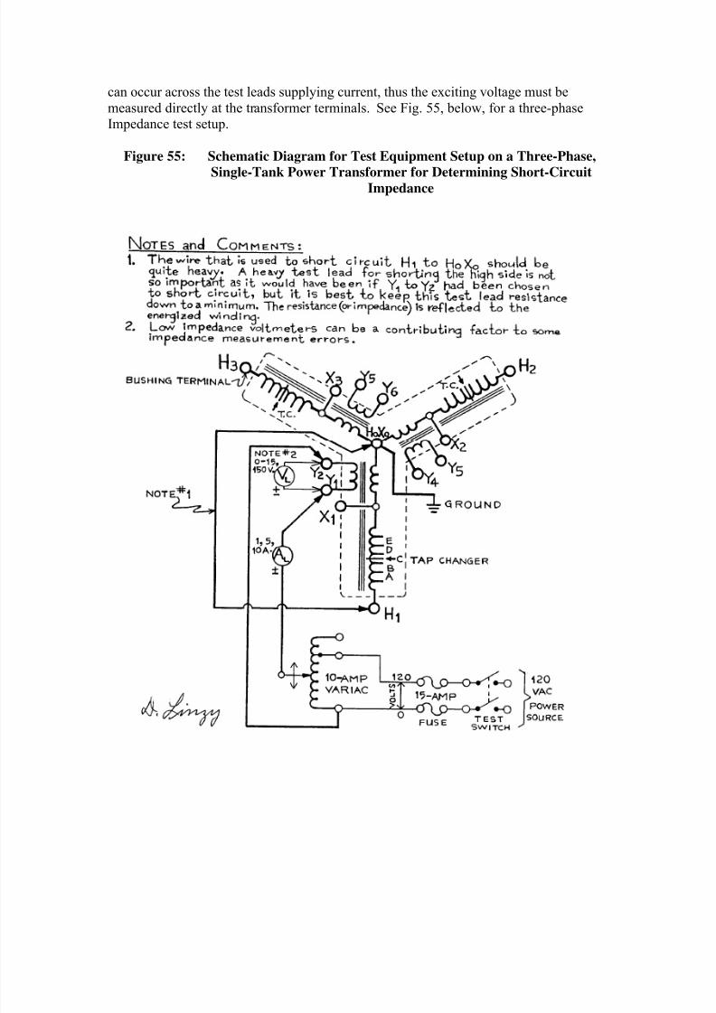
can occur across the test leads supplying current, thus the exciting voltage must be
measured directly at the transformer terminals. See Fig. 55, below, for a three-phaseImpedance test setup.
Figure 55: Schematic Diagram for Test Equipment Setup on a Three-Phase,
Single-Tank Power Transformer for Determining Short-CircuitImpedance
8/20/2019 SubstationCommissioning- Transformer Testing
http://slidepdf.com/reader/full/substationcommissioning-transformer-testing 23/83
On some transformers, measurement from the high-voltage side gives the closest
agreement with the nameplate. If measured impedance differs from the nameplate bymore than 5%, make the additional measurement for the alternate direction, or use the
phase-to-phase methods of Paragraph 1c equations (12, 13, and 14) for a Wye input and
Paragraph 3b Equations (5, 6, 7, and 8) for Delta input.
Large transformers have tap changers, and the % Z value is usually assigned at the
nominal (or middle) transformer tap position. The nominal value should be the
comparison point between manufacturer's data and field test data. The nameplate lists thevoltage tap at which nameplate % Z was measured.
Example:If a transformer has range positions of A, B, C, D, and E, the nominal position
would usually be "C." This tap value is generally specified at the rated operating
nameplate voltage of that transformer. If the range was from #1 through #17, tap #9would be the nominal tap. Test values are always recorded for the nominal tap as
well as for the upper and lower limits of the tap changer.
When the transformer is being energized with the test apparatus, the maximum excitationcurrent should be monitored very closely, because the variac used for test purposes can
be overloaded easily (usually only 10-amp capacity). Current can be very high, but the
voltage for this test is typically quite low.
The % Z calculations for short-circuit impedance measurements are actually based on the
nameplate rating of the winding being tested. The nameplate data for most transformersspecifies the total rating of the unit, and usually, just one value for the impedance is
given. The quantities to be selected for substitution into the formulas are not always thatobvious. E
MEASURED and I
MEASURED are easy because they will be readings obtained with
the measuring instruments. The kVARATED is based on the capacity of the winding being
shorted, and the formula makes use of the transformer nameplate rating (single phase orthree phase). The (kV)
2 is the line-to-line operating voltage of the winding being
energized for three-phase transformers, but it is also the actual winding operating voltage
for single-phase transformers. Following is the basis for the formulas that use KVA and
kV to calculate % Z:
%Z ZI
VMEASURED
RATED
RATED
100 (8.1)
Short-circuit impedance is derived from equation 8.1 and can be calculated for a three- phase wye-wye or wye-delta transformer using the following formula:
%( )
ZV
I
KVA
KV
MEASURED
MEASURED
RATED
L L
1
10
3
2
(8.2)
8/20/2019 SubstationCommissioning- Transformer Testing
http://slidepdf.com/reader/full/substationcommissioning-transformer-testing 24/83
Formula 8.2 is used for measuring impedance from a wye-connected winding. To test a
wye-delta transformer from a delta winding, the value 1/10 in the formula would bereplaced by 1/30. Avoid making up three-phase short circuits to speed up testing time;
error can be introduced if done improperly. Just short the appropriate winding on the
opposite side of the transformer and measure the short-circuit impedance. Be aware that
testing from the delta winding of a wye-delta transformer could add impedancemeasurement error because of the other two winding impedances. Note: Making up a
three-phase short to ground on the wye side and conducting the three impedance
measurements from the delta side cannot be done. Instead, short one wye winding at atime.
For a single-phase transformer, one of the three transformers used in a three-phase bank,the short-circuit impedance is derived from equation 8.1 and can be calculated by the
following formula:
%( )
ZV
I
KVA
KV
MEASURED
MEASURED
RATED
winding
1
10
1
2
(8.3)
For single-phase transformers, formula 8.3 works regardless from which side impedance
is measured.
There can be some confusion when trying to do calculations, because field-testing
instrumentation is set up to measure single-phase impedance values. Single-phase
impedance is more directive in identifying which winding may have a problem, but won’talways derive the same number given on the nameplate. For example, an impedance
measurement done for a Delta-Delta transformer will yield a value that is twice the
nameplate % Z. This is because the manufacturer lists the impedance as a three-phase-
wye equivalent through impedance. The nameplate % Z on three-phase transformers
connected Y-Y, Y-, -Y, or - can be matched by shorting all three secondary bushings together and applying test quantities phase to phase on the unshorted side. The
average of the three impedance measurements should match the nameplate % Z. This is
accomplished by replacing VMEASURED in equation 8.4 with the average of all three testvoltages [(VAB+VBC+VCA MEASURED)/3]. Also, remember that what is being measured
is the total leakage impedance of the short-circuit path (two nameplate impedance values
in series). The % Z will calculate as follows:
)(
2
3
20
1%
L L
RATED
MEASURED
MEASURED
KV
KVA
I
V Z
(8.4)
Note: Formula 8.4 is used for measuring impedance in delta-delta transformers and
requires a three-phase short circuit on the winding opposite the measured side.
Impedance is measured as a phase-to-phase test.
With the exception of delta-delta transformers, since they do not have a wye winding,
three-phase transformers can be tested single-phase from the wye winding side with a
8/20/2019 SubstationCommissioning- Transformer Testing
http://slidepdf.com/reader/full/substationcommissioning-transformer-testing 25/83
three-phase short (connected to neutral for wye configuration) using the conventional
equation (8.2). This cannot be done on delta-delta transformers because there is no wayto short only one set of windings. Any short applied to one winding is also short-
circuiting the other two windings of the delta connection and test current would flow to
some extent in all transformer windings. The same case applies to wye winding
configurations that do not have the neutral connection brought out. Because calculating% Z is so varied, it leaves the door open for mistakes and/or improper testing
connections. Always calculate the % Z from measured test quantities, verifying they arecorrect and correspond to the transformer nameplate values, prior to tearing down the test
set-up. This way extra checks can be made if needed.
Practice making impedance calculations before actually doing them, because there maynot be time to do it when testing under outage conditions. Refer to one of the filled-out
test data sheets in the appendix, if an example of impedance measurement is desired.
8.9.1 ZERO-SEQUENCE IMPEDANCE
Zero-sequence current and voltage values are important quantities to provide proper relay
protection of power lines and substation equipment. Zero-sequence quantities having anyreal significance generally occur only when a power system becomes unbalanced due to
nonsymmetrical power loading or because of a fault.
For a three-phase power system, zero-sequence current flows when one or two phases are
faulted to ground. The correct operation of ground relays requires proper zero-sequence
relay current and (for directional relays) polarizing quantities during the fault.
Delta-wye transformers with grounded wye neutrals are the major sources of zero-
sequence-current flow within a power system. Depending on a transformer’sconfiguration, zero-sequence currents can flow through the transformer, from the
transformer, or both.
To describe zero-sequence impedance testing on a transformer, a grounded wye
(sometimes called a star configuration) connection is used. Zigzag transformers are
tested for zero-sequence impedance by the same test connections. Measuring zero-sequence impedance of a transformer is relatively easy; the test connection diagram of
Fig. 56 illustrates the connections and equipment needed. A variation of the impedance
formula is required to compute the impedance for zigzag or other grounding transformers(shown in Equation 8.5).
Begin by shorting all three wye bushings together (X1 to X2 to X3) = (X123) while leavingthe high-side terminals open from ground. Apply a single-phase voltage from "X123" to
"X0" while simultaneously measuring both voltage and current. These values can then be
substituted into the following formula to calculate zero-sequence impedance:
8/20/2019 SubstationCommissioning- Transformer Testing
http://slidepdf.com/reader/full/substationcommissioning-transformer-testing 26/83
%( )
( )Z
V
I
KVA
KV
MEASURED
MEASURED
RATED
L L
1
10
3 3
2
(8.5)
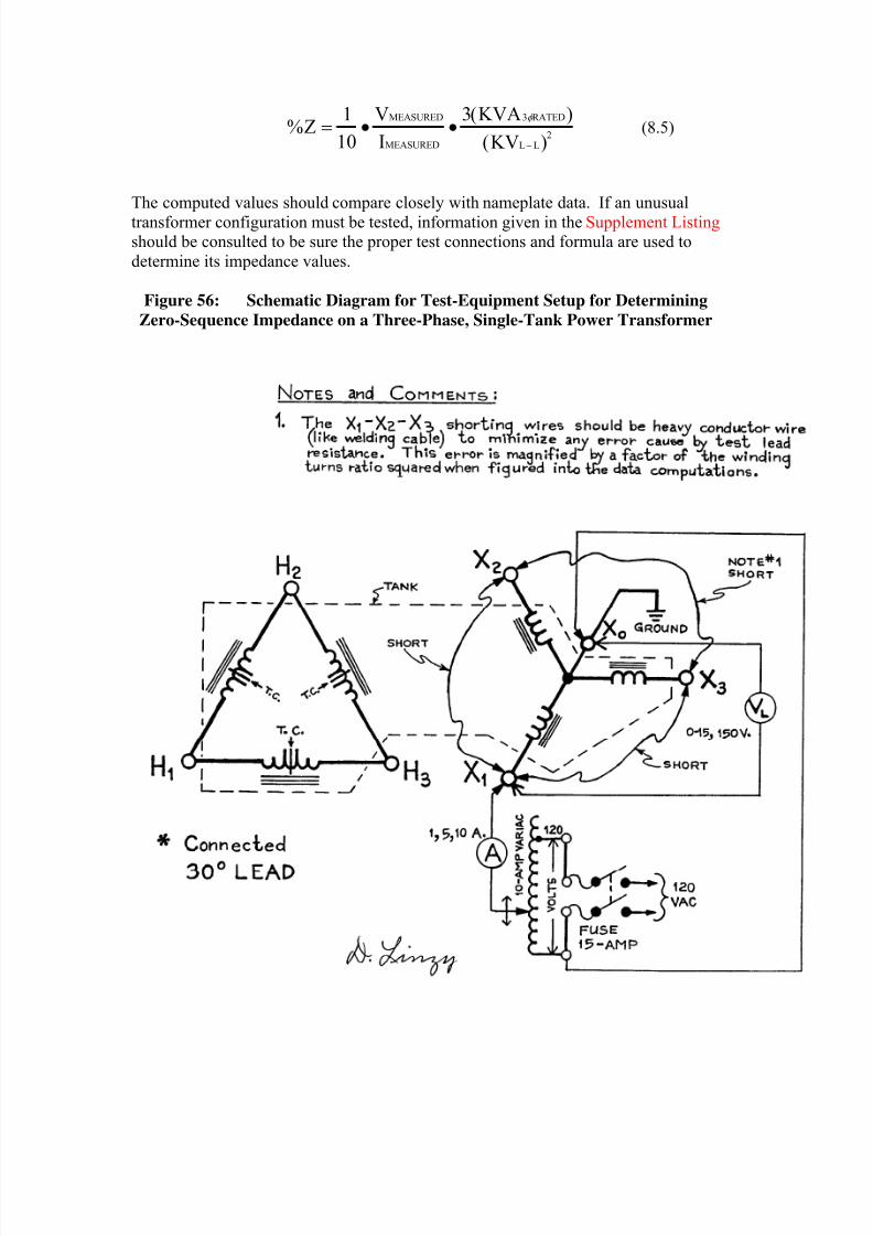
The computed values should compare closely with nameplate data. If an unusual
transformer configuration must be tested, information given in the Supplement Listing should be consulted to be sure the proper test connections and formula are used to
determine its impedance values.
Figure 56: Schematic Diagram for Test-Equipment Setup for Determining
Zero-Sequence Impedance on a Three-Phase, Single-Tank Power Transformer
8/20/2019 SubstationCommissioning- Transformer Testing
http://slidepdf.com/reader/full/substationcommissioning-transformer-testing 27/83
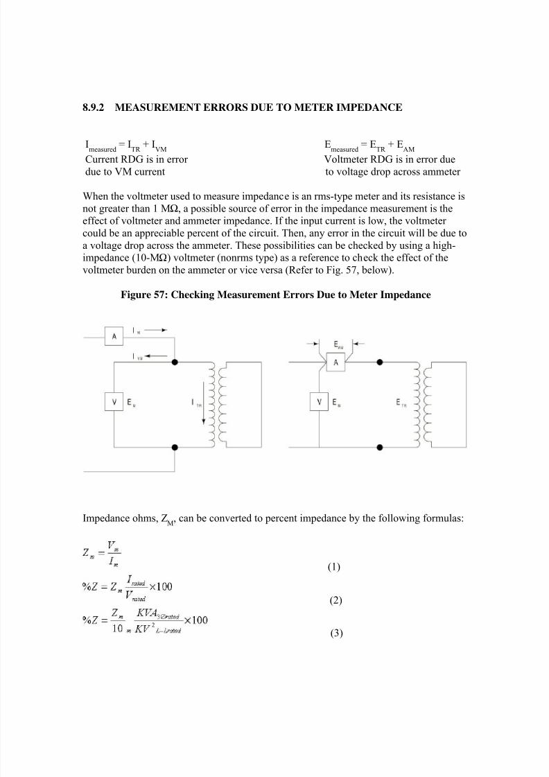
8.9.2 MEASUREMENT ERRORS DUE TO METER IMPEDANCE
Imeasured
= ITR
+ IVM
Emeasured
= ETR
+ EAM
Current RDG is in error Voltmeter RDG is in error due
due to VM current to voltage drop across ammeter
When the voltmeter used to measure impedance is an rms-type meter and its resistance is
not greater than 1 MΩ, a possible source of error in the impedance measurement is theeffect of voltmeter and ammeter impedance. If the input current is low, the voltmeter
could be an appreciable percent of the circuit. Then, any error in the circuit will be due to
a voltage drop across the ammeter. These possibilities can be checked by using a high-impedance (10-MΩ) voltmeter (nonrms type) as a reference to check the effect of the
voltmeter burden on the ammeter or vice versa (Refer to Fig. 57, below).
Figure 57: Checking Measurement Errors Due to Meter Impedance
Impedance ohms, ZM
, can be converted to percent impedance by the following formulas:
(1)
(2)
(3)
8/20/2019 SubstationCommissioning- Transformer Testing
http://slidepdf.com/reader/full/substationcommissioning-transformer-testing 28/83
Changing to a new KVA base:
(4)Changing to a new voltage base:
(5)
8.10 VOLTAGE RATIO AND POLARITY MEASUREMENTS ON TWO-PHASE
OR THREE-PHASE TRANSFORMERS
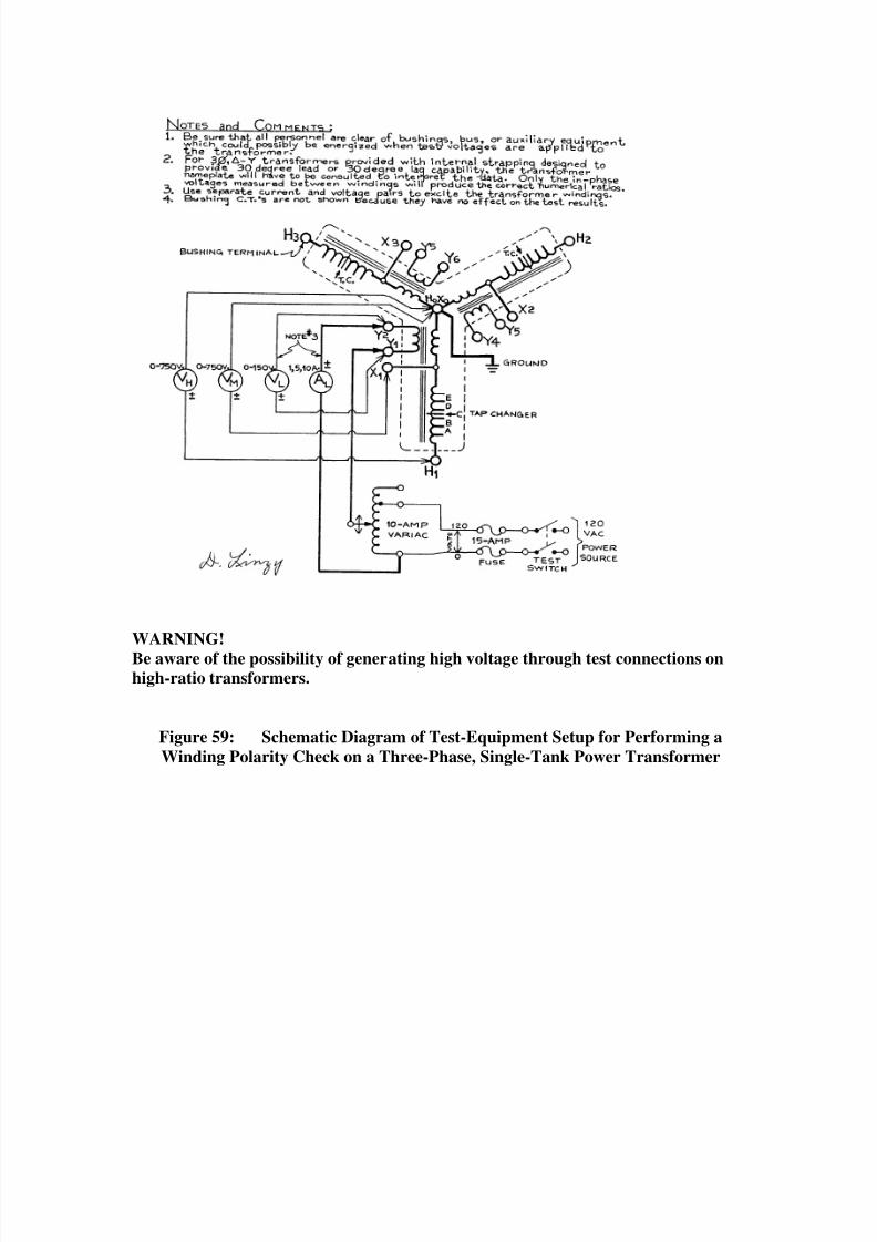
Methodology for Voltage Ratio and Polarity measurements is the same for single-phaseas for two- and three-phase machines. See Section 8.8 for details. Following (Figs. 58-59) are two schematics of test setups for three-phase transformers.
Figure 58: Schematic Diagram of Test-Equipment Setup for Performing Voltage
Ratio Measurements on a Three-Phase, Single-Tank Power Transformer
8/20/2019 SubstationCommissioning- Transformer Testing
http://slidepdf.com/reader/full/substationcommissioning-transformer-testing 29/83
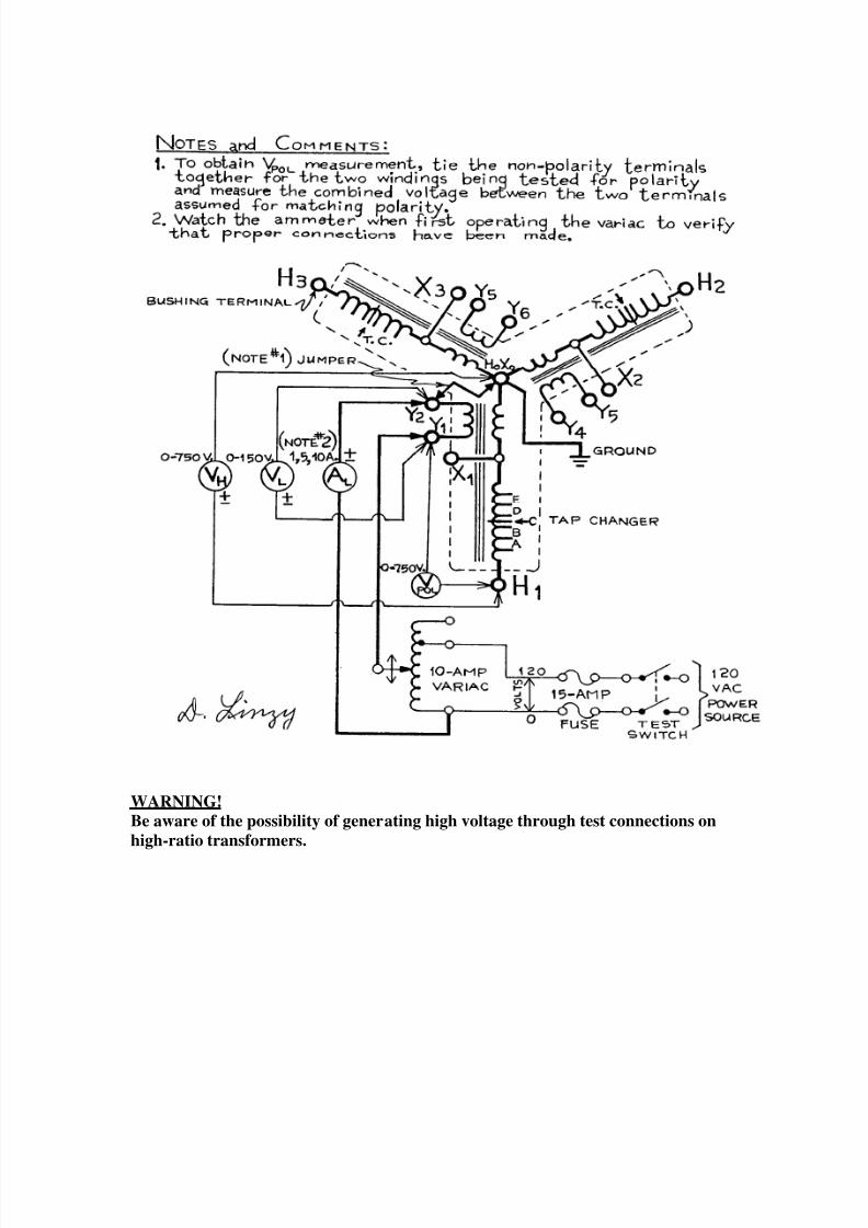
WARNING!
Be aware of the possibility of generating high voltage through test connections onhigh-ratio transformers.
Figure 59: Schematic Diagram of Test-Equipment Setup for Performing a
Winding Polarity Check on a Three-Phase, Single-Tank Power Transformer
8/20/2019 SubstationCommissioning- Transformer Testing
http://slidepdf.com/reader/full/substationcommissioning-transformer-testing 30/83
WARNING! Be aware of the possibility of generating high voltage through test connections on
high-ratio transformers.
8/20/2019 SubstationCommissioning- Transformer Testing
http://slidepdf.com/reader/full/substationcommissioning-transformer-testing 31/83
WARNING!
Do not attempt to test any transformer that is being processed for drying, either
while under vacuum or while hot oil is being circulated through the main tank. It is
not prudent to walk around on a tank while it is under a full vacuum. An additional
restriction applies, because an electric charge can be generated in the windings
while oil is being heated (for drying) and circulated through the tank.
Before energizing the test circuit, everyone in the work area must be informed andadvised to stay in the clear while electrical tests are being performed. When selecting the
actual voltages to be measured and recorded on the data sheet for the ratio test, make sure
all voltages will stay below dangerous levels (there may be a step-up voltage hazard). It is
not practical, and usually not possible, to attempt these tests at full-rated voltages with theavailable test apparatus.
Three-phase transformers that are constructed so they do not cause a voltage phase shift
from the high side to the low side (Y - Y or - ) measure directly with nameplate kV.
Ratio measurements can be more difficult if a phase-shifting connection is involved (Y - or - Y), because winding ratio is being measured and a ratio factor of 3 is involved.
The internal winding connections of many three-phase transformers in the 115-kV class
can be changed to obtain either a 30-degree leading or 30-degree lagging output voltage.
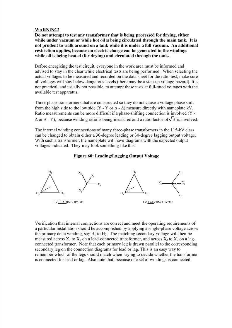
With such a transformer, the nameplate will have diagrams with the expected outputvoltages indicated. They may look something like this:
Figure 60: Leading/Lagging Output Voltage
H2
H3
H1
X2X0
X3
X1
LV LEADING BY 30
H2
H3H1
LV LAGGING BY 30
X3
X0
X2
X1
Verification that internal connections are correct and meet the operating requirements of
a particular installation should be accomplished by applying a single-phase voltage acrossthe primary delta winding, say H1 to H2. The matching secondary voltage will then be
measured across X1 to X0 on a lead-connected transformer, and across X2 to X0 on a lag-connected transformer. Note that each primary leg is drawn parallel to the corresponding
secondary leg on the connection diagrams for lead or lag. This is an easy way to
remember which of the legs should match when trying to decide whether the transformeris connected for lead or lag. Also note that, because one set of windings is connected
8/20/2019 SubstationCommissioning- Transformer Testing
http://slidepdf.com/reader/full/substationcommissioning-transformer-testing 32/83
delta, voltages will be measurable on the other two phases, but they will be 1/2 the proper
magnitude.
WARNING!
Test voltages on transformer banks with high turns ratios can generate lethal
voltages, e.g., 120 V applied X1 to X0 on a 230-kV delta to 13.8 kV wye transformerbank will generate 3.5 kV between two of the H-side terminals (bushings).
Also, note that one winding is connected phase to phase and the other is phase to neutral.
Be aware that the expected voltage is based on the transformer winding turns ratio and
not the kV ratio (primary to secondary). Exercise caution, because misapplication of
voltage could generate lethal voltage at the transformer terminals. Because of the hands-on nature of this test, apply test voltages to the highest voltage winding rather than the
other way around.
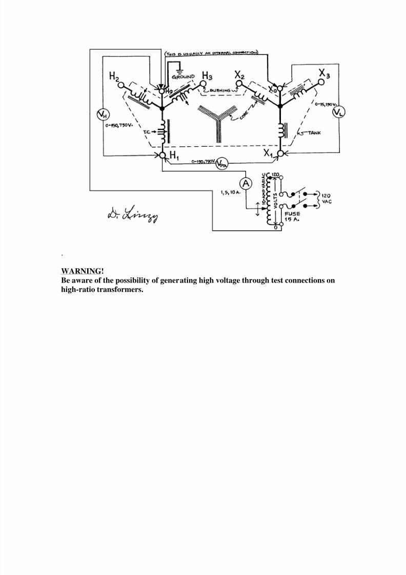
Figs. 61 and 62, below, are simplified schematic diagrams illustrating how test
instruments can be connected to perform Ratio and Polarity tests on Y-Y and -Ytransformers. The significance of these two examples is that the delta-wye connection is
probably the most common winding configuration that will be encountered for medium
sized, single-tank transformers in the 12-MVA to 50-MVA range.
Figure 61: Connections for the Voltage Ratio and Polarity tests on a Wye-Wye
(Y-Y) Transformer
8/20/2019 SubstationCommissioning- Transformer Testing
http://slidepdf.com/reader/full/substationcommissioning-transformer-testing 33/83
.
WARNING!
Be aware of the possibility of generating high voltage through test connections on
high-ratio transformers.
8/20/2019 SubstationCommissioning- Transformer Testing
http://slidepdf.com/reader/full/substationcommissioning-transformer-testing 34/83
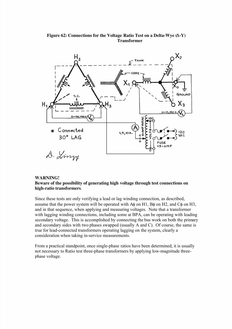
Figure 62: Connections for the Voltage Ratio Test on a Delta-Wye (
-Y)
Transformer
WARNING!
Beware of the possibility of generating high voltage through test connections on
high-ratio transformers.
Since these tests are only verifying a lead or lag winding connection, as described,
assume that the power system will be operated with A on H1, B on H2, and C on H3,and in that sequence, when applying and measuring voltages. Note that a transformer
with lagging winding connections, including some at BPA, can be operating with leading
secondary voltage. This is accomplished by connecting the bus work on both the primaryand secondary sides with two phases swapped (usually A and C). Of course, the same is
true for lead-connected transformers operating lagging on the system, clearly aconsideration when taking in-service measurements.
From a practical standpoint, once single-phase ratios have been determined, it is usually
not necessary to Ratio test three-phase transformers by applying low-magnitude three- phase voltage.
8/20/2019 SubstationCommissioning- Transformer Testing
http://slidepdf.com/reader/full/substationcommissioning-transformer-testing 35/83
Polarity The polarity of the windings is easily checked at the same time the voltage ratio is beingtested. The diagrams in Figs. 59 and 61 apply to Y-Y-connected transformers, Fig. 62 to
-Y-connected transformers. The important concern when performing a polarity check isto tie the nonpolarity ends of the two separate windings together and measure across the
polarity ends. The resultant voltage will either be the sum or difference of the twoseparate winding voltages, a sum indicating additive and a difference indicatingsubtractive polarity. Transformers above 500 kVA are built with subtractive polarity.
8.11 TAP CHANGERS
Tap changers allow transformer input and output voltages to be matched with the rest of
the power system or to adjust voltage levels between power sources and customers. They
allow transformers to be applied in situations where voltage control would be verydifficult without utilizing additional expensive equipment..
Tap changers are either “no load” (NL) or “under load” (UL) control devices. No loadmeans that the transformer must be de-energized before an operator may change tap positions. Under load means that tap positions can be changed while the transformer is
energized and carrying power. UL tap changers allow transformers to be used as voltage
regulating devices; however, the other method for voltage regulation on the power systemis through the use of shunt capacitors and reactors using circuit switchers and/or breakers
to switch them on and off line
While Voltage Ratio, Impedance, Resistance, and TTR tests are being performed, the tap-
changer mechanism must be operated to get test data under all available tap settings.
When the Ratio test is performed, all possible tap positions should be checked for both
NL and UL tap changers. This is especially important for a new transformer. Limitedassistance may be available in the manufacturer's instruction books for personnel who arenot familiar with these mechanisms.
When a NL tap changer is tested, a small amount of current is applied to excite the tap
winding, and a meter monitoring the output winding is carefully observed to determinewhere windings are dropped out and picked up during tap changes. This check should be
used to verify that tap-changer contacts are properly centered, and that they actually do
open and make up at the correct point between tap changes. All tap changers must havetheir contacts firmly and correctly placed when in a tap position. On some tap changers
there is some spring pressure felt when manually changing from tap to tap. This pressure
should be consistent on manually operated (NL) tap changers when moving from one position to another, either up or down. Note that NL tap changers actually create an open
circuit during tap change transitions. If they do not appear to operate correctly,
investigate!
When testing UL tap changers, excitation current should be monitored continuously to
verify that the winding is NEVER open-circuited. The tap-changer mechanism checklist
(BPA Form No. 77) is a useful guideline to assure that all the important tests have been
8/20/2019 SubstationCommissioning- Transformer Testing
http://slidepdf.com/reader/full/substationcommissioning-transformer-testing 36/83
done. This list is somewhat self-explanatory, and the specified checks can be
accomplished without detailed instructions .
Both local and remote operation and indication of UL tap changers must be verified.
Remote operation from the control house should be tested completely. The limits of the
control should be checked to see that the tap changer will not go beyond its stops. CheckSCADA control over the entire operating range. Make sure that the local and remote
position readings match. Check for operation with the supervisory cutoff switch in boththe "on" and "off" positions.
8.12 SPECIFIC RATIO AND IMPEDANCE CALCULATIONS FOR THREE-
PHASE TWO-WINDING TRANSFORMERS
This section presents single-phase test procedures that may be used to measure the ratio,impedance, and zero-sequence impedance of three-phase two-winding transformers.
Refer to Sections 8.1, 8.7, and 8.8 for diagnostic procedures.
In many cases direct measurement of either ratio or impedance is not possible. Several
formulas use the sum and difference of measured quantities to determine winding ratio or
impedance. Desired accuracy for these parameters will require measurement accuracies
of 1% or less. Average impedance of a three-phase unit is useful for quick comparisonwith nameplate values. However, for diagnostic purposes test measurements should
provide sufficient data so that coil impedance in % Z can be determined. In the % Z
formulas, Irated
and Erated
refer to rated current and voltage of the energized winding.
Impedance of each phase of a three-phase transformer can be determined, regardless of
how its windings are connected, by using the phase-to-phase input methods of Fig. 63C
Equations (12, 13, and 14) for a Wye input and Fig. 65B Equations (5, 6, 7, and 8) for a
Delta input. Depending on core design and winding assembly, small differences inmeasured impedance will occur between the phase-to-phase method and the phase-to-neutral method of measuring % Z.
In the following examples of single-phase test procedures for measuring ratios,
impedance and zero-sequence impedance of three-phase two-winding transformers, winding terminals are designated “a,” “b,” “c,” and “n” for the input windings and “1,”
“2,” “3,” and “0” for the output windings. Where applicable, alternate connections of the
output windings are shown. Designated transformer terminals are accessible during thetest.
Three-phase diagrams for each transformer connection are used to show each winding ofa three-phase two-winding transformer. A secondary coil, which is on the same core leg,
is shown parallel with its corresponding primary winding. For example: In Fig.63C, a to
n is in-phase with and on the same core leg as 1 to 0 or 0 to 1; b to n is in-phase with andon the same core leg as 2 to 0 or 0 to 2; and c to n is in phase with and on the same core
leg as 3 to 0 or 0 to 3. System phase designations do not necessarily correspond with
these secondary designations.
8/20/2019 SubstationCommissioning- Transformer Testing
http://slidepdf.com/reader/full/substationcommissioning-transformer-testing 37/83
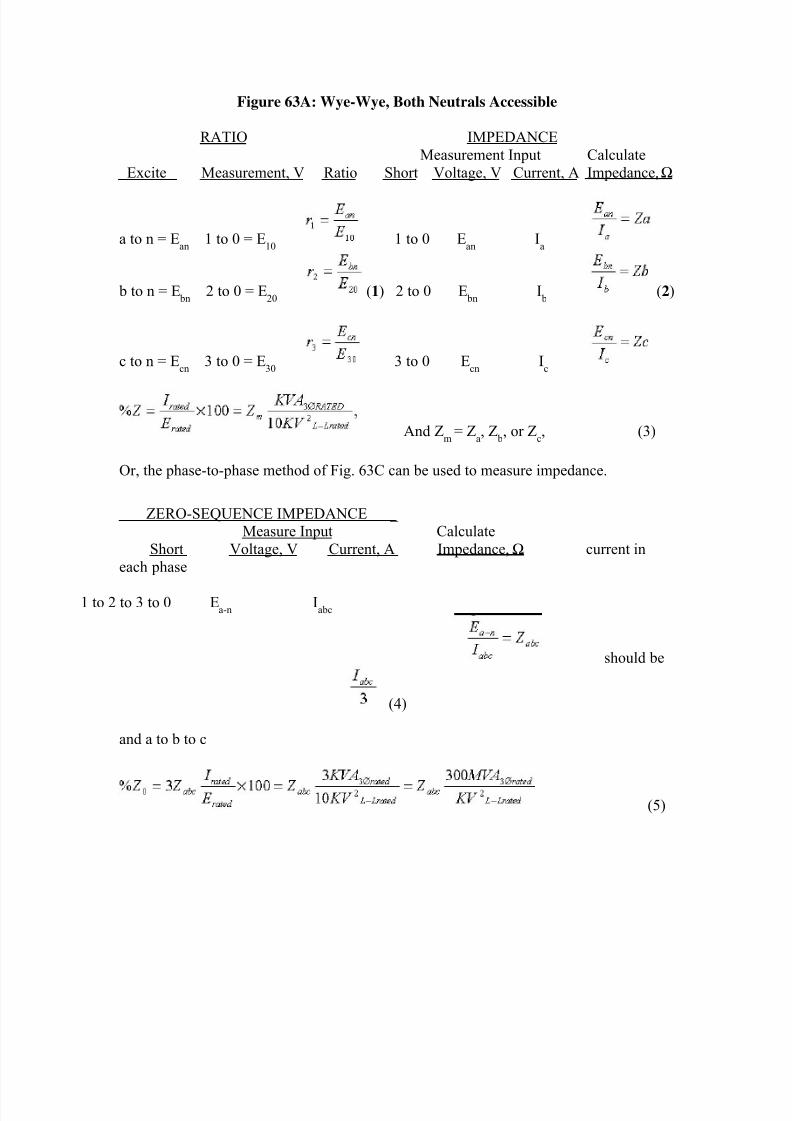
Figure 63A: Wye-Wye, Both Neutrals Accessible
RATIO IMPEDANCE
Measurement Input Calculate
Excite Measurement, V Ratio Short Voltage, V Current, A Impedance, Ω
a to n = Ean
1 to 0 = E10
1 to 0 Ean
Ia
b to n = E bn
2 to 0 = E20
(1) 2 to 0 E bn
I b
(2)
c to n = Ecn
3 to 0 = E30
3 to 0 Ecn
Ic
And Zm
= Za, Z
b, or Z
c, (3)
Or, the phase-to-phase method of Fig. 63C can be used to measure impedance.
ZERO-SEQUENCE IMPEDANCE _Measure Input Calculate
Short Voltage, V Current, A Impedance, Ω current in
each phase
1 to 2 to 3 to 0 Ea-n
Iabc
should be
(4)
and a to b to c
(5)
8/20/2019 SubstationCommissioning- Transformer Testing
http://slidepdf.com/reader/full/substationcommissioning-transformer-testing 38/83
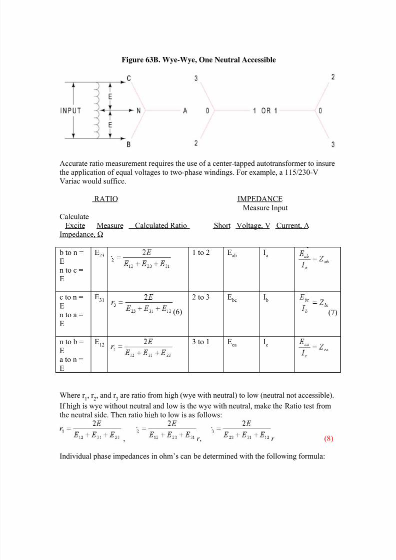
Figure 63B. Wye-Wye, One Neutral Accessible
Accurate ratio measurement requires the use of a center-tapped autotransformer to insure
the application of equal voltages to two-phase windings. For example, a 115/230-VVariac would suffice.
RATIO IMPEDANCEMeasure Input
Calculate
Excite Measure Calculated Ratio Short Voltage, V Current, AImpedance, Ω
b to n =E
n to c =E
E23 1 to 2 Eab Ia
c to n =En to a =
E
E31
(6)
2 to 3 E bc I b
(7)
n to b =
Ea to n =
E
E12 3 to 1 Eca Ic
Where r 1, r
2, and r
3 are ratio from high (wye with neutral) to low (neutral not accessible).
If high is wye without neutral and low is the wye with neutral, make the Ratio test from
the neutral side. Then ratio high to low is as follows:
, r , r (8)
Individual phase impedances in ohm’s can be determined with the following formula:
8/20/2019 SubstationCommissioning- Transformer Testing
http://slidepdf.com/reader/full/substationcommissioning-transformer-testing 39/83
, , , (9)
(10)
And Zm = Za, Z b, or Zc,
Or, the phase-to-phase method of Fig. 63C can be used to measure impedance.
ZERO-SEQUENCE IMPEDANCE
Infinite for wye input.
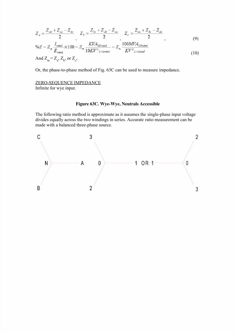
Figure 63C. Wye-Wye, Neutrals Accessible
The following ratio method is approximate as it assumes the single-phase input voltagedivides equally across the two windings in series. Accurate ratio measurement can be
made with a balanced three-phase source.
8/20/2019 SubstationCommissioning- Transformer Testing
http://slidepdf.com/reader/full/substationcommissioning-transformer-testing 40/83
Individual phase impedances in ohms can be determined with the following formula:
, , , (13)
(14)And Z
m= Z
a, Z
b, or Z
c,
ZERO-SEQUENCE IMPEDANCE
Infinite for wye input.
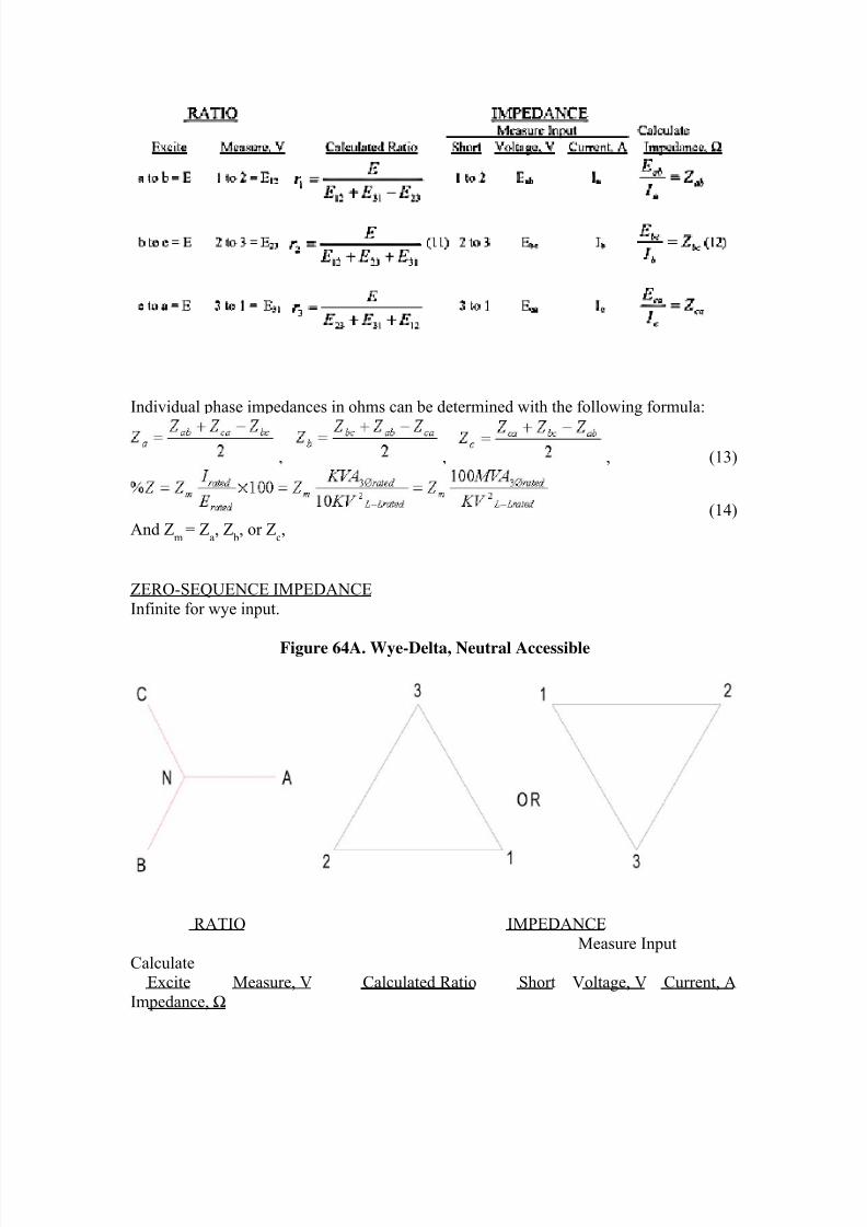
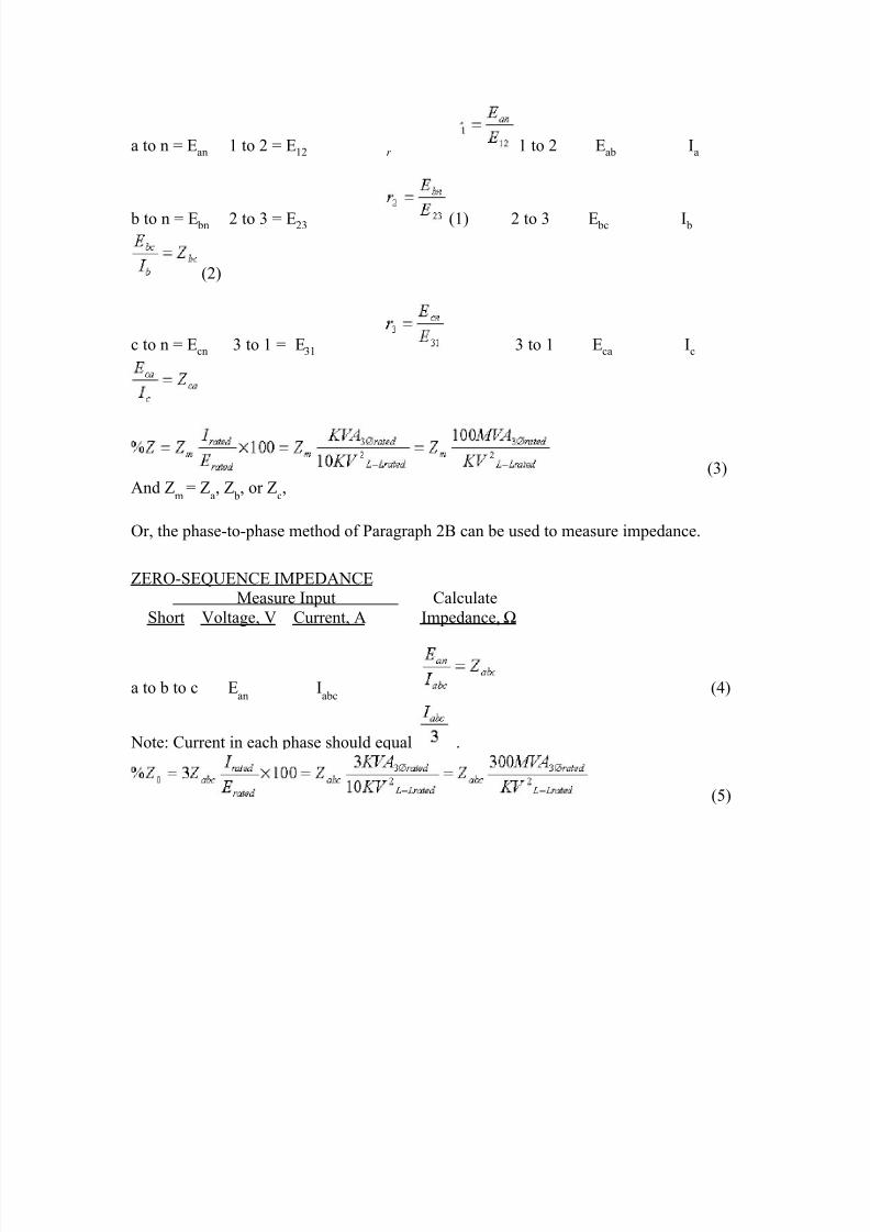
Figure 64A. Wye-Delta, Neutral Accessible
RATIO IMPEDANCE
Measure Input
CalculateExcite Measure, V Calculated Ratio Short Voltage, V Current, A
Impedance, Ω
8/20/2019 SubstationCommissioning- Transformer Testing
http://slidepdf.com/reader/full/substationcommissioning-transformer-testing 41/83
a to n = Ean 1 to 2 = E12 r 1 to 2 Eab Ia
b to n = E bn 2 to 3 = E23 (1) 2 to 3 E bc I b
(2)
c to n = Ecn 3 to 1 = E31 3 to 1 Eca Ic
(3)And Z
m= Z
a, Z
b, or Z
c,
Or, the phase-to-phase method of Paragraph 2B can be used to measure impedance.
ZERO-SEQUENCE IMPEDANCEMeasure Input Calculate
Short Voltage, V Current, A Impedance, Ω
a to b to c Ean
Iabc
(4)
Note: Current in each phase should equal .
(5)
8/20/2019 SubstationCommissioning- Transformer Testing
http://slidepdf.com/reader/full/substationcommissioning-transformer-testing 42/83
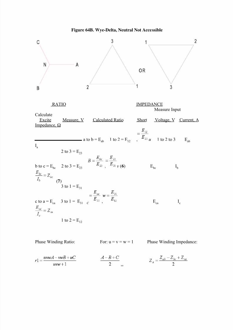
Figure 64B. Wye-Delta, Neutral Not Accessible
RATIO IMPEDANCEMeasure Input
CalculateExcite Measure, V Calculated Ratio Short Voltage, V Current, A
Impedance, Ω
a to b = Eab 1 to 2 = E12 , u 1 to 2 to 3 Eab
Ia
2 to 3 = E23
b to c = E bc 2 to 3 = E23 , v (6) E bc I b
(7)3 to 1 = E31
c to a = Eca 3 to 1 = E31 C , Eca Ic
1 to 2 = E12
Phase Winding Ratio: For: u = v = w = 1 Phase Winding Impedance:
=
8/20/2019 SubstationCommissioning- Transformer Testing
http://slidepdf.com/reader/full/substationcommissioning-transformer-testing 43/83
(8) (9)
(10)And Z
m= Z
a, Z
b, or Z
c,
ZERO-SEQUENCE IMPEDANCE
Infinite for Wye input
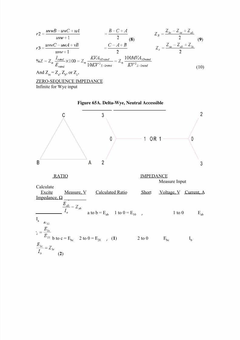
Figure 65A. Delta-Wye, Neutral Accessible
RATIO IMPEDANCE
Measure Input
Calculate
Excite Measure, V Calculated Ratio Short Voltage, V Current, AImpedance, Ω
a to b = Eab 1 to 0 = E10 r 1 to 0 Eab
Ia
b to c = E bc 2 to 0 = E20 r (1) 2 to 0 E bc I b
(2)
8/20/2019 SubstationCommissioning- Transformer Testing
http://slidepdf.com/reader/full/substationcommissioning-transformer-testing 44/83
c to a = Eca 3 to 0 = E30 3 to 0 Eca Ic
And Zm
= Za, Z
b, or Z
c, (3)
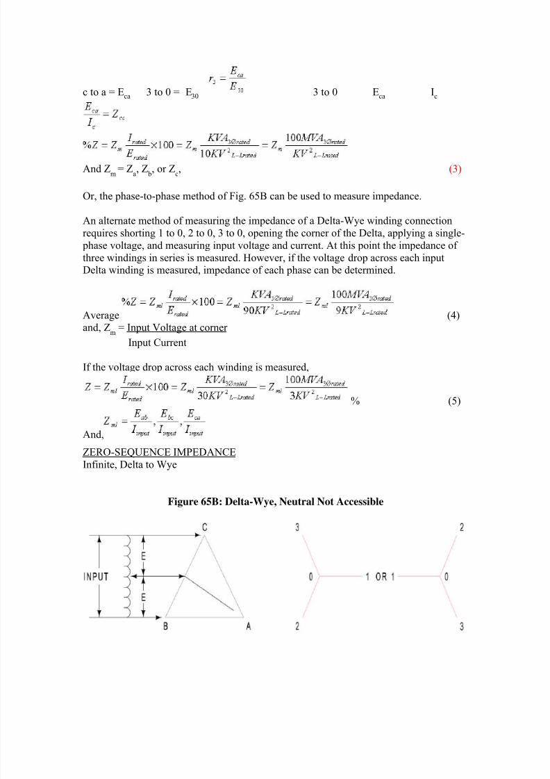
Or, the phase-to-phase method of Fig. 65B can be used to measure impedance.
An alternate method of measuring the impedance of a Delta-Wye winding connection
requires shorting 1 to 0, 2 to 0, 3 to 0, opening the corner of the Delta, applying a single-
phase voltage, and measuring input voltage and current. At this point the impedance of
three windings in series is measured. However, if the voltage drop across each input
Delta winding is measured, impedance of each phase can be determined.
Average (4)and, Z
m = Input Voltage at corner
Input Current
If the voltage drop across each winding is measured,
% (5)
And,
ZERO-SEQUENCE IMPEDANCE
Infinite, Delta to Wye
Figure 65B: Delta-Wye, Neutral Not Accessible
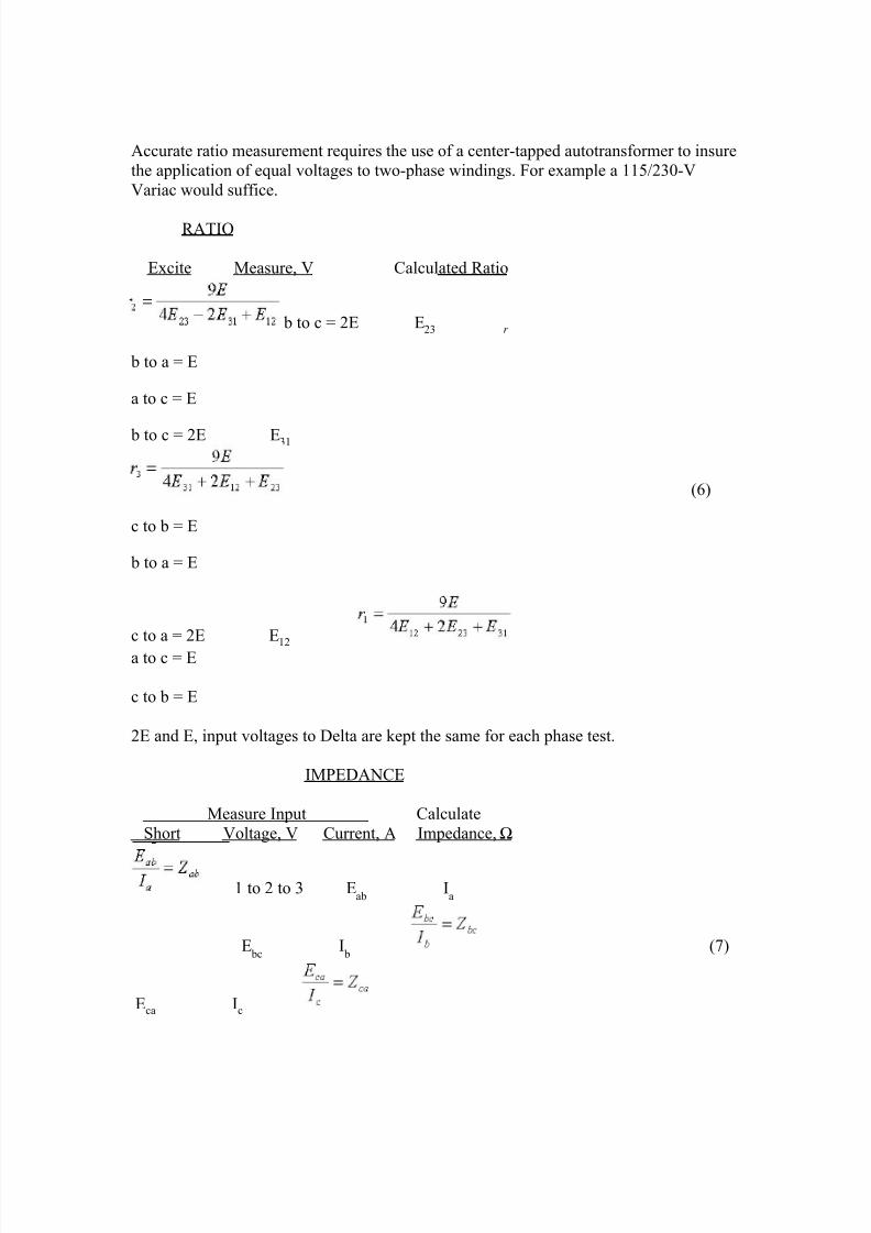
8/20/2019 SubstationCommissioning- Transformer Testing
http://slidepdf.com/reader/full/substationcommissioning-transformer-testing 45/83
Accurate ratio measurement requires the use of a center-tapped autotransformer to insure
the application of equal voltages to two-phase windings. For example a 115/230-V
Variac would suffice.
RATIO
Excite Measure, V Calculated Ratio
b to c = 2E E23 r
b to a = E
a to c = E
b to c = 2E E31
(6)
c to b = E
b to a = E
c to a = 2E E12
a to c = E
c to b = E
2E and E, input voltages to Delta are kept the same for each phase test.
IMPEDANCE
Measure Input Calculate
Short Voltage, V Current, A Impedance, Ω
1 to 2 to 3 Eab
Ia
E bc
I b (7)
Eca Ic
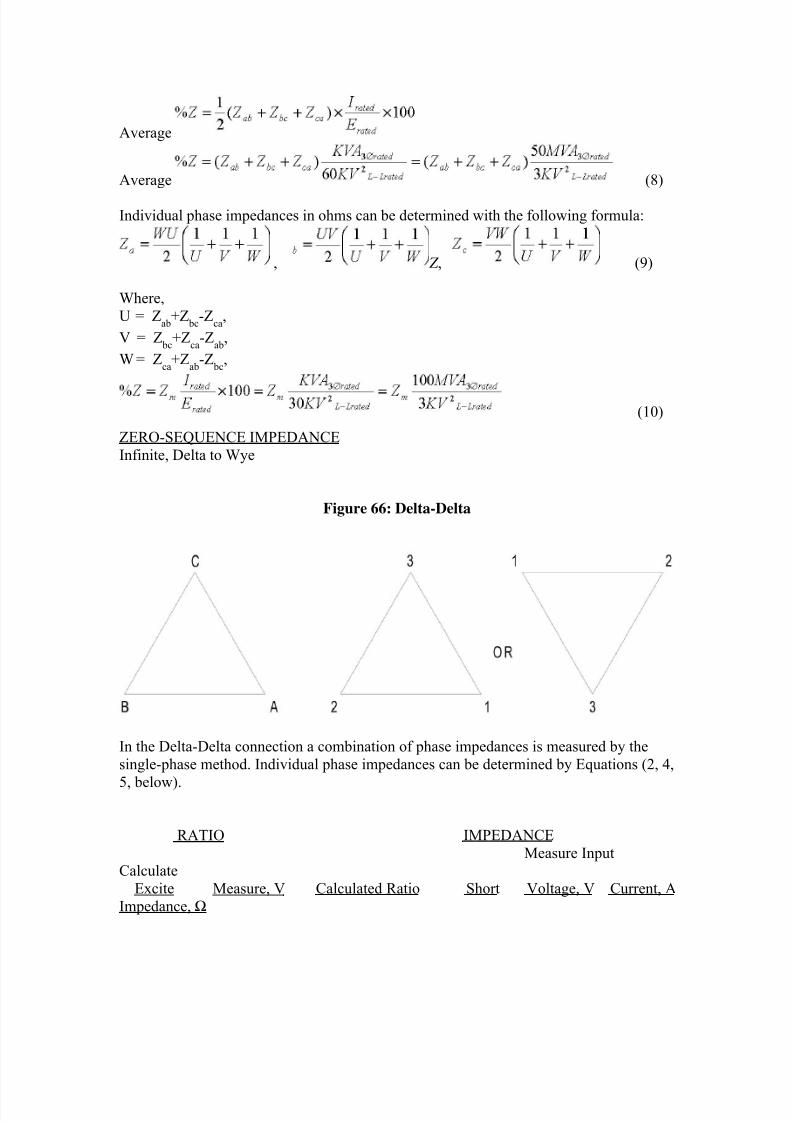
8/20/2019 SubstationCommissioning- Transformer Testing
http://slidepdf.com/reader/full/substationcommissioning-transformer-testing 46/83
Average
Average (8)
Individual phase impedances in ohms can be determined with the following formula:
, Z , (9)
Where,
U = Z
ab+Z
bc-Z
ca,
V = Z bc
+Zca
-Zab
,
W = Z
ca+Z
ab-Z
bc,
(10)
ZERO-SEQUENCE IMPEDANCE
Infinite, Delta to Wye
Figure 66: Delta-Delta
In the Delta-Delta connection a combination of phase impedances is measured by the
single-phase method. Individual phase impedances can be determined by Equations (2, 4,
5, below).
RATIO IMPEDANCE
Measure InputCalculate
Excite Measure, V Calculated Ratio Short Voltage, V Current, A
Impedance, Ω
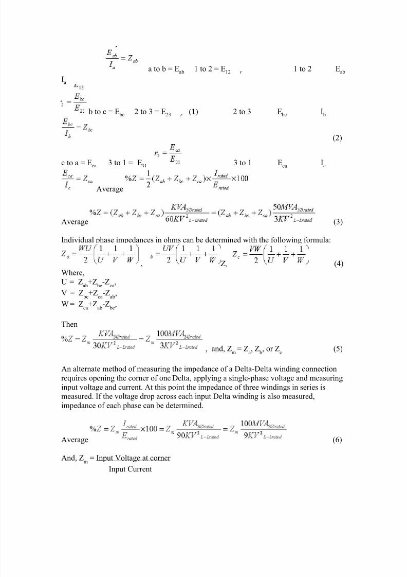
8/20/2019 SubstationCommissioning- Transformer Testing
http://slidepdf.com/reader/full/substationcommissioning-transformer-testing 47/83
a to b = Eab 1 to 2 = E12 r 1 to 2 Eab
Ia
b to c = E bc 2 to 3 = E23 r (1) 2 to 3 E bc I b
(2)
c to a = Eca 3 to 1 = E31 3 to 1 Eca Ic
Average
Average (3)
Individual phase impedances in ohms can be determined with the following formula:
, Z , (4)
Where,
U = Z
ab+Z
bc-Z
ca,
V = Z bc
+Zca
-Zab
,
W = Zca+Zab-Z bc,
Then
, and, Zm
= Za, Z
b, or Z
c (5)
An alternate method of measuring the impedance of a Delta-Delta winding connection
requires opening the corner of one Delta, applying a single-phase voltage and measuring
input voltage and current. At this point the impedance of three windings in series ismeasured. If the voltage drop across each input Delta winding is also measured,
impedance of each phase can be determined.
Average (6)
And, Zm
= Input Voltage at corner
Input Current
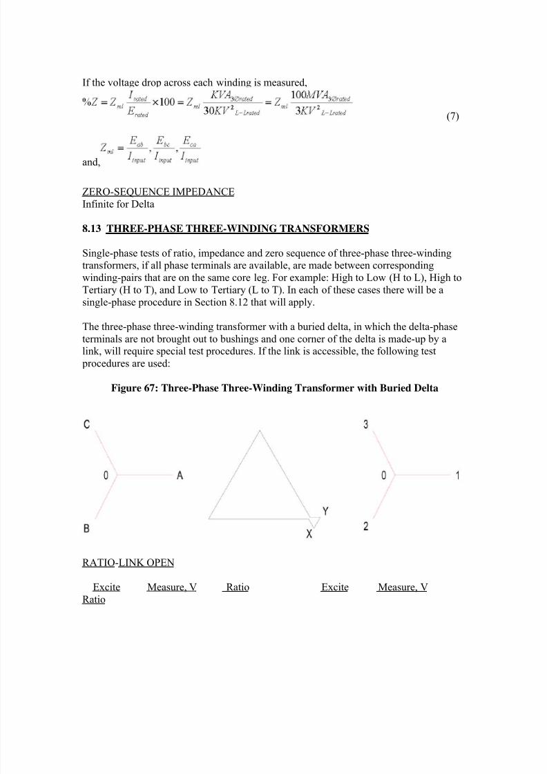
8/20/2019 SubstationCommissioning- Transformer Testing
http://slidepdf.com/reader/full/substationcommissioning-transformer-testing 48/83
If the voltage drop across each winding is measured,
(7)
and,
ZERO-SEQUENCE IMPEDANCE
Infinite for Delta
8.13 THREE-PHASE THREE-WINDING TRANSFORMERS
Single-phase tests of ratio, impedance and zero sequence of three-phase three-windingtransformers, if all phase terminals are available, are made between corresponding
winding-pairs that are on the same core leg. For example: High to Low (H to L), High to
Tertiary (H to T), and Low to Tertiary (L to T). In each of these cases there will be a
single-phase procedure in Section 8.12 that will apply.
The three-phase three-winding transformer with a buried delta, in which the delta-phase
terminals are not brought out to bushings and one corner of the delta is made-up by alink, will require special test procedures. If the link is accessible, the following test
procedures are used:
Figure 67: Three-Phase Three-Winding Transformer with Buried Delta
RATIO-LINK OPEN
Excite Measure, V Ratio Excite Measure, V
Ratio
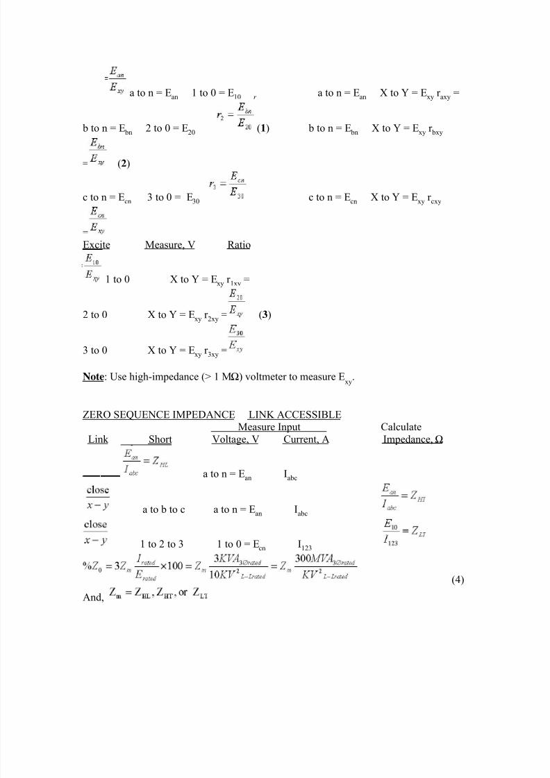
8/20/2019 SubstationCommissioning- Transformer Testing
http://slidepdf.com/reader/full/substationcommissioning-transformer-testing 49/83
a to n = Ean 1 to 0 = E10 r a to n = Ean X to Y = Exy r axy =
b to n = E bn 2 to 0 = E20 (1) b to n = E bn X to Y = Exy r bxy
= (2)
c to n = Ecn 3 to 0 = E30 c to n = Ecn X to Y = Exy r cxy
=Excite Measure, V Ratio
1 to 0 X to Y = Exy r 1xy =
2 to 0 X to Y = Exy r 2xy = (3)
3 to 0 X to Y = Exy r 3xy =
Note: Use high-impedance (> 1 MΩ) voltmeter to measure Exy
.
ZERO SEQUENCE IMPEDANCE LINK ACCESSIBLEMeasure Input Calculate
Link Short Voltage, V Current, A Impedance, Ω
a to n = Ean Iabc
a to b to c a to n = Ean Iabc
1 to 2 to 3 1 to 0 = Ecn I123
(4)
And,
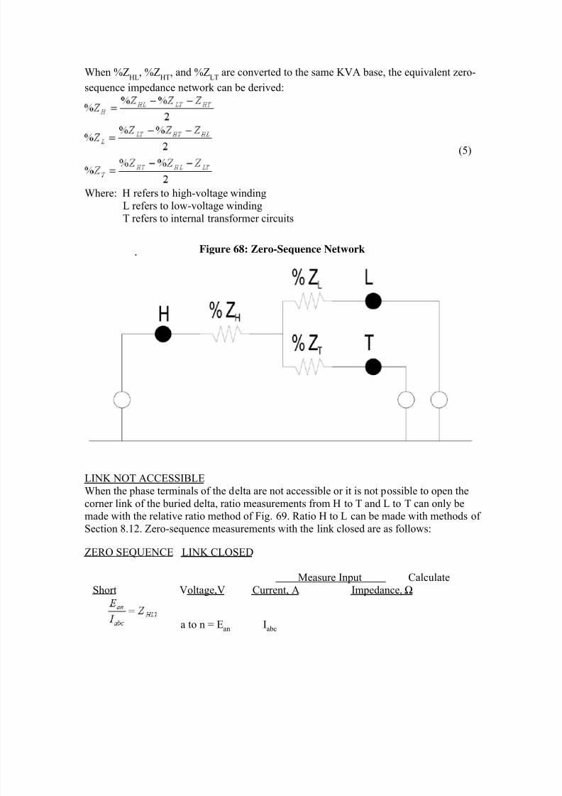
8/20/2019 SubstationCommissioning- Transformer Testing
http://slidepdf.com/reader/full/substationcommissioning-transformer-testing 50/83
When %ZHL
, %ZHT
, and %ZLT
are converted to the same KVA base, the equivalent zero-
sequence impedance network can be derived:
(5)
Where: H refers to high-voltage winding
L refers to low-voltage winding
T refers to internal transformer circuits
Figure 68: Zero-Sequence Network
LINK NOT ACCESSIBLE
When the phase terminals of the delta are not accessible or it is not possible to open the
corner link of the buried delta, ratio measurements from H to T and L to T can only bemade with the relative ratio method of Fig. 69. Ratio H to L can be made with methods of
Section 8.12. Zero-sequence measurements with the link closed are as follows:
ZERO SEQUENCE LINK CLOSED
Measure Input Calculate
Short Voltage,V Current, A Impedance, Ω
a to n = Ean Iabc
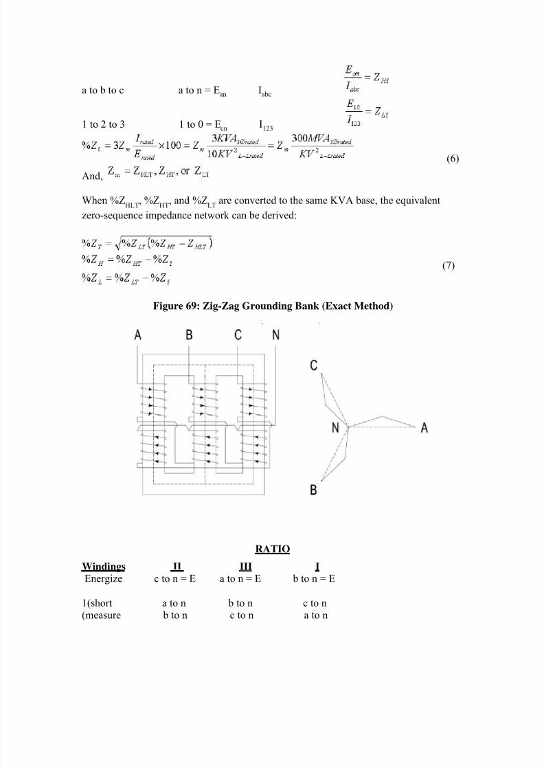
8/20/2019 SubstationCommissioning- Transformer Testing
http://slidepdf.com/reader/full/substationcommissioning-transformer-testing 51/83
a to b to c a to n = Ean Iabc
1 to 2 to 3 1 to 0 = Ecn I123
(6)
And,
When %ZHLT
, %ZHT
, and %ZLT
are converted to the same KVA base, the equivalent
zero-sequence impedance network can be derived:
(7)
Figure 69: Zig-Zag Grounding Bank (Exact Method)
RATIO
Windings II III I
Energize c to n = E a to n = E b to n = E
1(short a to n b to n c to n(measure b to n c to n a to n
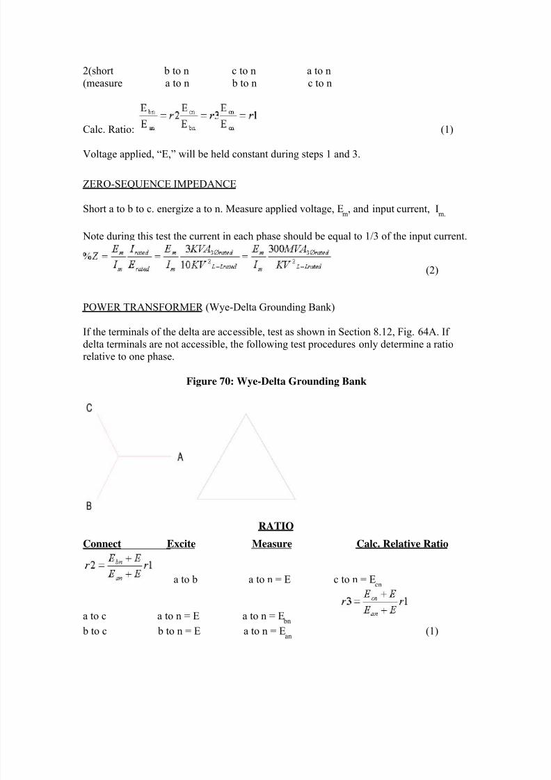
8/20/2019 SubstationCommissioning- Transformer Testing
http://slidepdf.com/reader/full/substationcommissioning-transformer-testing 52/83
2(short b to n c to n a to n
(measure a to n b to n c to n
Calc. Ratio: (1)
Voltage applied, “E,” will be held constant during steps 1 and 3.
ZERO-SEQUENCE IMPEDANCE
Short a to b to c. energize a to n. Measure applied voltage, Em
, and input current, Im.
Note during this test the current in each phase should be equal to 1/3 of the input current.
(2)
POWER TRANSFORMER (Wye-Delta Grounding Bank)
If the terminals of the delta are accessible, test as shown in Section 8.12, Fig. 64A. If
delta terminals are not accessible, the following test procedures only determine a ratiorelative to one phase.
Figure 70: Wye-Delta Grounding Bank
RATIO
Connect Excite Measure Calc. Relative Ratio
a to b a to n = E c to n = Ecn
a to c a to n = E a to n = E bn
b to c b to n = E a to n = Ean
(1)
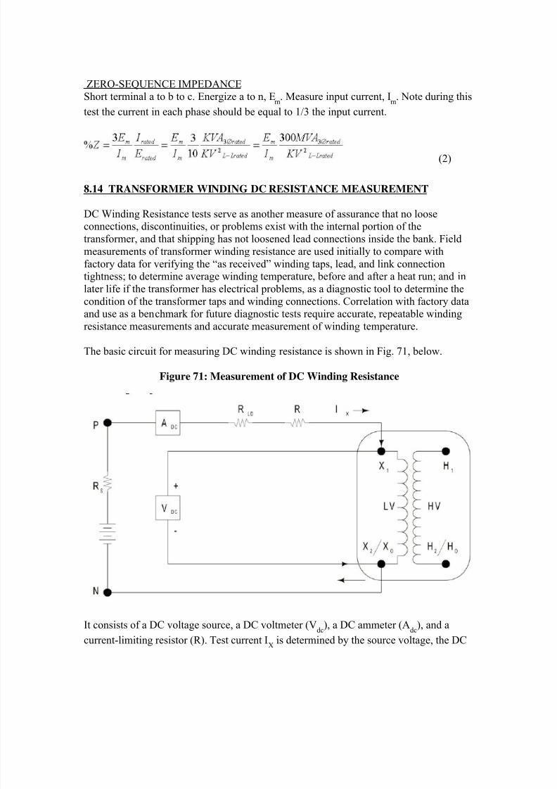
8/20/2019 SubstationCommissioning- Transformer Testing
http://slidepdf.com/reader/full/substationcommissioning-transformer-testing 53/83
ZERO-SEQUENCE IMPEDANCEShort terminal a to b to c. Energize a to n, E
m. Measure input current, I
m. Note during this
test the current in each phase should be equal to 1/3 the input current.
(2)
8.14 TRANSFORMER WINDING DC RESISTANCE MEASUREMENT
DC Winding Resistance tests serve as another measure of assurance that no looseconnections, discontinuities, or problems exist with the internal portion of the
transformer, and that shipping has not loosened lead connections inside the bank. Field
measurements of transformer winding resistance are used initially to compare with
factory data for verifying the “as received” winding taps, lead, and link connection
tightness; to determine average winding temperature, before and after a heat run; and inlater life if the transformer has electrical problems, as a diagnostic tool to determine the
condition of the transformer taps and winding connections. Correlation with factory dataand use as a benchmark for future diagnostic tests require accurate, repeatable winding
resistance measurements and accurate measurement of winding temperature.
The basic circuit for measuring DC winding resistance is shown in Fig. 71, below.
Figure 71: Measurement of DC Winding Resistance
It consists of a DC voltage source, a DC voltmeter (Vdc
), a DC ammeter (Adc
), and a
current-limiting resistor (R). Test current IX is determined by the source voltage, the DC
8/20/2019 SubstationCommissioning- Transformer Testing
http://slidepdf.com/reader/full/substationcommissioning-transformer-testing 54/83
source internal resistance (R S), the resistance of current test leads (R
LD), the resistance of
the current-limiting resistor (R), and with a very minor effect, winding resistance. If theDC source is a 12-V car battery and a test current, I
X, of approximately 1 A is desired,
resistance, R, would be 10 Ω/25 W. If the source is a regulated DC supply, R = 0.
Winding resistance is calculated from the measured steady-state voltage drop across thewinding and the final magnitude of current, I
X. Initially, voltage will be high and current
will be low. And, depending on winding inductance and charging-circuit resistance, it
will take 30 seconds to 2 minutes to reach final steady-state values. Test requirements areas follows:
• DC current, IX, must be less than 15% of the winding’s rated current to prevent
heating by the test current.• Connect voltmeter leads inside the current connection closest to the winding.
• Time required to reach steady values should be noted.
• Resistance measurements should not be attempted when ambient temperature isfluctuating.
• Temperature should be measured before and after DC resistance measurements
(ambient, top-oil, case, etc.).
• After being energized from the power system, the cold winding resistance canonly be measured after winding and oil temperature have stabilized.
Safety
Before proceeding with any measurements in a high-voltage substation, the test engineermust be thoroughly familiar with requirements of Section 2. Make sure the transformer
bank being tested is de-energized, out of service, and isolated from the power system
before climbing or connecting it to any test leads.
WARNING!
Winding-resistance measurements may require 1 A to 100 A DC for accurate
measurements. When the bank has been charged up with a DC current, use extreme
caution to protect the tester and the test instrument from the
collapse of the flux, which discharges considerable energy stored in the
winding -- enough to damage the test instrument and cause personal injury.
WARNING!
Never be positioned in series with a test lead by touching the transformer bushing
terminal with one hand and holding the test lead in the other. Warn all participantsin the test of the possibility of hazardous voltages.
Energy stored in the transformer winding being measured is proportional to winding
inductance, L in Henries, and the square of the DC test current level, IX, by the following:
W LI X
2 Watt-seconds (1)
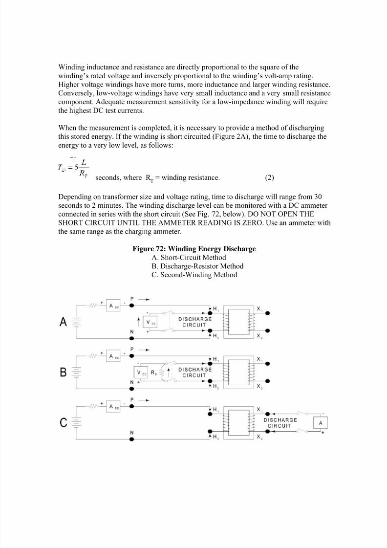
8/20/2019 SubstationCommissioning- Transformer Testing
http://slidepdf.com/reader/full/substationcommissioning-transformer-testing 55/83
Winding inductance and resistance are directly proportional to the square of the
winding’s rated voltage and inversely proportional to the winding’s volt-amp rating.
Higher voltage windings have more turns, more inductance and larger winding resistance.
Conversely, low-voltage windings have very small inductance and a very small resistancecomponent. Adequate measurement sensitivity for a low-impedance winding will require
the highest DC test currents.
When the measurement is completed, it is necessary to provide a method of discharging
this stored energy. If the winding is short circuited (Figure 2A), the time to discharge the
energy to a very low level, as follows:
seconds, where R T = winding resistance. (2)
Depending on transformer size and voltage rating, time to discharge will range from 30
seconds to 2 minutes. The winding discharge level can be monitored with a DC ammeterconnected in series with the short circuit (See Fig. 72, below). DO NOT OPEN THE
SHORT CIRCUIT UNTIL THE AMMETER READING IS ZERO. Use an ammeter with
the same range as the charging ammeter.
Figure 72: Winding Energy Discharge
A. Short-Circuit Method
B. Discharge-Resistor MethodC. Second-Winding Method
8/20/2019 SubstationCommissioning- Transformer Testing
http://slidepdf.com/reader/full/substationcommissioning-transformer-testing 56/83
Time to discharge can be reduced by connecting a discharge resistor, R D, across the
winding (Fig. 72B) before reducing test current to zero,
seconds, where: R D>> R
T(3)
The maximum voltage produced across the discharge resistor is
Volts. (4)
As shown by Equations (3) and (4), the higher the discharge resistance, the shorter the
discharge times, but the higher the discharge voltage. Peak discharge voltage can belimited to 100 V if the discharge resistance is determined as follows:
Ohms (5)
Thus, before de-energizing the test current source, provide a path to discharge the stored
energy. If the current-carrying test lead is prematurely lifted or inadvertently
disconnected, the open-circuit resistance is very high (R D
=∞) and the corresponding
voltage, VD, between transformer terminal and test lead will be in kilovolts.
Arcing will occur between bushing terminal and test lead. If the DC current is de-
energized without provisions for discharging the transformer’s stored energy, the high
voltage generated by the collapse of the field in the winding will arc through open
switches and damage the test equipment.
When an external discharge resistor is used, it is possible to monitor the windingdischarge by measuring the voltage across the discharge resistor, R
D (Figure 72B). When
this voltage is zero, test leads may be cautiously removed.
An alternate discharge path can be provided by temporarily short circuiting a winding (onthe same phase) that is not being tested (See Fig. 72C). A DC Ammeter can monitor the
short-circuit current. Its current range will follow the inverse turns ratio and current
direction will correspond with the polarity marking of the two windings.
For example, if 1A is going in the H1 bushing, current will be going to the X
1 bushing
during discharge with the X-winding. And, if the H and X ratio is 10 to 1, the meter scaleshould be 10 A. The short circuit should make a low-resistance connection and not be
applied during the resistance measurement procedure.
WARNING!
Do not lift the short circuit until the discharge current is zero.
8/20/2019 SubstationCommissioning- Transformer Testing
http://slidepdf.com/reader/full/substationcommissioning-transformer-testing 57/83
8.14.1 TEST CONNECTIONS
Measurement of winding resistance requires that test connections be made directly to the
winding terminals and not through bus or conductors connected externally to the bushing.Test-lead wire size must be adequate for the test current and test leads should be soldered
to their spade-lugs, clips, and clamps.
Connections to winding terminals must be clean, low resistance, and secured so there is
no possibility of a test lead inadvertently being pulled loose or falling off. On a low-
resistance winding the connection to the bushing terminal could be an appreciable part ofthe total resistance. In the case of four terminal measurements, connect the current leads
outside and the potential leads nearest to the resistance being measured.
The effects of stray fields from current-carrying overhead lines or nearby bus can be
minimized by keeping test leads short. Although test leads are to be kept at minimallengths, any excess test lead length should be laid side-by-side and not coiled.
8.14.2 WINDING TEMPERATURE
Temperature measurements can be made with the transformer thermometer used to
measure top oil. A laboratory-type thermometer immersed in the top oil can be held
against the case with duc-seal or putty at several levels and peripheral locations on the
transformer case to establish average case temperature, which will approximate windingtemperature. Inside oil temperature and outside case temperatures can be equalized by
running one stage of the oil pumps and making measurements before sunrise, after sunsetin the late afternoon, or during cloudy weather. If winding resistance is measured during
sunny periods, winding temperature can be established by averaging top-oil temperature
and bottom-case temperature measured on the shady side.
Temperature measurements of a transformer removed from service will require several
hours to stabilize case, oil, and winding temperature.
8.14.3 DC RESISTANCE MEASUREMENT (Tap Changers)
On transformer banks with newly assembled tap changers, it is desirable to bridge the
winding for each tap position. Make resistance measurements on each tap position of the
step-voltage regulator. In general, bridge overall every winding. When tap changers are
used, it is necessary to operate them several times over their full range to establish lowtap-contact resistance by their wiping action. For copper windings, resistance R
X,
measured at temperature TX
, can be converted to the base temperature T
B as follows:
(6)
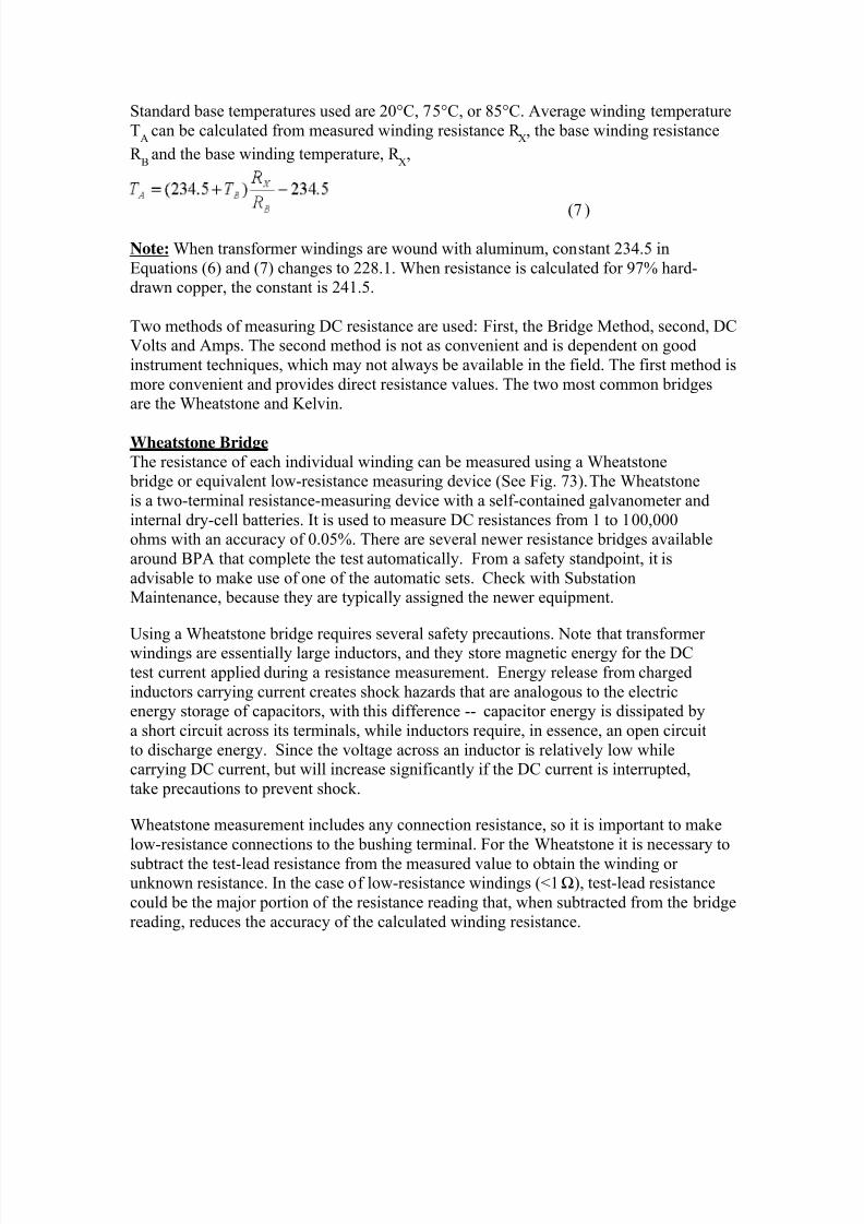
8/20/2019 SubstationCommissioning- Transformer Testing
http://slidepdf.com/reader/full/substationcommissioning-transformer-testing 58/83
Standard base temperatures used are 20°C, 75°C, or 85°C. Average winding temperature
TA
can be calculated from measured winding resistance R X, the base winding resistance
R B
and the base winding temperature, R X,
(7 )
Note: When transformer windings are wound with aluminum, constant 234.5 in
Equations (6) and (7) changes to 228.1. When resistance is calculated for 97% hard-drawn copper, the constant is 241.5.
Two methods of measuring DC resistance are used: First, the Bridge Method, second, DCVolts and Amps. The second method is not as convenient and is dependent on good
instrument techniques, which may not always be available in the field. The first method is
more convenient and provides direct resistance values. The two most common bridgesare the Wheatstone and Kelvin.
Wheatstone Bridge
The resistance of each individual winding can be measured using a Wheatstone bridge or equivalent low-resistance measuring device (See Fig. 73). The Wheatstone
is a two-terminal resistance-measuring device with a self-contained galvanometer and
internal dry-cell batteries. It is used to measure DC resistances from 1 to 100,000ohms with an accuracy of 0.05%. There are several newer resistance bridges available
around BPA that complete the test automatically. From a safety standpoint, it is
advisable to make use of one of the automatic sets. Check with SubstationMaintenance, because they are typically assigned the newer equipment.
Using a Wheatstone bridge requires several safety precautions. Note that transformerwindings are essentially large inductors, and they store magnetic energy for the DC
test current applied during a resistance measurement. Energy release from charged
inductors carrying current creates shock hazards that are analogous to the electricenergy storage of capacitors, with this difference -- capacitor energy is dissipated by
a short circuit across its terminals, while inductors require, in essence, an open circuit
to discharge energy. Since the voltage across an inductor is relatively low whilecarrying DC current, but will increase significantly if the DC current is interrupted,
take precautions to prevent shock.
Wheatstone measurement includes any connection resistance, so it is important to make
low-resistance connections to the bushing terminal. For the Wheatstone it is necessary to
subtract the test-lead resistance from the measured value to obtain the winding orunknown resistance. In the case of low-resistance windings (<1Ω), test-lead resistance
could be the major portion of the resistance reading that, when subtracted from the bridge
reading, reduces the accuracy of the calculated winding resistance.
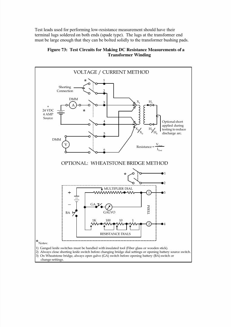
8/20/2019 SubstationCommissioning- Transformer Testing
http://slidepdf.com/reader/full/substationcommissioning-transformer-testing 59/83
Test leads used for performing low-resistance measurement should have their
terminal lugs soldered on both ends (spade type). The lugs at the transformer endmust be large enough that they can be bolted solidly to the transformer bushing pads.
Figure 73: Test Circuits for Making DC Resistance Measurements of a
Transformer Winding
V
1
2
3
4
5
6
ShortingConnection
+24 VDC
4 AMPSource
DMM
DMM
H1
X1
H2H
0
X2X
0
Optional shortapplied duringtesting to reducedischarge arc.
*
*
VOLTAGE / CURRENT METHOD
1
2
*
1 3
GA
GALVO
1K 100 10 1
RESISTANCE DIALS
2 4
T E R M
MULTIPLIER DIAL
BA
OPTIONAL: WHEATSTONE BRIDGE METHOD
*Notes:
1) Ganged knife switches must be handled with insulated tool (Fiber glass or wooden stick).2) Always close shorting knife switch before changing bridge dial settings or opening battery source switch.3) On Wheatstone bridge, always open galvo (GA) switch before opening battery (BA) switch or change settings.
A
VTest
ITest
Resistance =
8/20/2019 SubstationCommissioning- Transformer Testing
http://slidepdf.com/reader/full/substationcommissioning-transformer-testing 60/83
Test-lead wires used for testing larger transformers should be #12 copper or larger to
speed up the charging rate. Depending on the size of the transformer and thecondition of the batteries in the bridge, charging times may be 30 minutes or longer
per winding. Some resistance bridges have a provision for using an external battery
to supply charging current, a convenient feature if testing three or four largetransformers on the same day. Note: Transformer windings opposite of those
being bridged can be short-circuited to reduce inductive kick on discharge of the
test winding. Although this will increase charge time, it may reduce test time overall
when using a Wheatstone bridge. This is because there is no real worry aboutdamaging the bridge while dialing in the resistance on the bridge. All the same,
realize that the resistance dials create open circuits during dial position changes and
that the test procedure could injure the bridge if done improperly.
When a stable reading is attained on the bridge, the galvanometer readout should beheld on for a few minutes before the final reading is recorded. The reading will be
stable at the point where charging current quits changing. After taking a reading the
charging source is disconnected, but then consider how to discharge the transformer
winding. Create a short-circuit discharge path across the test leads prior todisconnecting the charging potential source (See Fig. 73).
CAUTION! To prevent damage to the Wheatstone Bridge's galvanometer, always release the
GALVO button first before cutting out the bridge battery (BA button) and whenmaking changes to multiplier settings or, if used, disconnecting an external battery.
Breaking the DC current generates a voltage when the magnetic energy is discharged
from a transformer winding, and it can damage the sensitive galvanometer.
To prevent damage when the bridge is not being used or is in transit, block thegalvanometer. Also, before using the bridge make certain that fresh D-cell batteries
have been installed and the galvanometer is on its null reference (See Fig. 73).
WARNING!
For personal safety, do not pull the test leads from the transformer while it is
being charged. Do not handle test circuit connections without using an
insulating device to handle the wires and connections until the test circuit has
been completely discharged. The winding inductance can generate a large arc,
which has severe shock potential to test personnel, when the charge path is
broken. Shock due to inductive discharge is traumatic and could possibly cause
a workman to fall off the transformer. Some test personnel connect extrashorting wires across the output terminals of the bridge upon completion of the
test, to insure that the transformer is not discharged through the instrument or
themselves. A suggestion is to wire an extra knife switch into the test circuit,
shorting the test leads to the transformer and disconnecting the DC resistance
bridge. Before making test-lead changes, give the winding plenty of time to
discharge (at least five minutes).
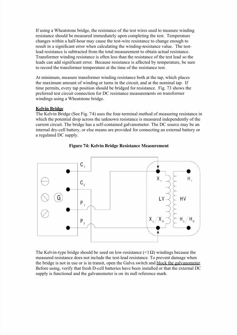
8/20/2019 SubstationCommissioning- Transformer Testing
http://slidepdf.com/reader/full/substationcommissioning-transformer-testing 61/83
If using a Wheatstone bridge, the resistance of the test wires used to measure winding
resistance should be measured immediately upon completing the test. Temperaturechanges within a half-hour may cause the test-wire resistance to change enough to
result in a significant error when calculating the winding-resistance value. The test-
lead resistance is subtracted from the total measurement to obtain actual resistance.
Transformer winding resistance is often less than the resistance of the test lead so theleads can add significant error. Because resistance is affected by temperature, be sure
to record the transformer temperature at the time of the resistance test.
At minimum, measure transformer winding resistance both at the tap, which places
the maximum amount of winding or turns in the circuit, and at the nominal tap. Iftime permits, every tap position should be bridged for resistance. Fig. 73 shows the
preferred test circuit connection for DC resistance measurements on transformer
windings using a Wheatstone bridge.
Kelvin Bridge
The Kelvin Bridge (See Fig. 74) uses the four-terminal method of measuring resistance in
which the potential drop across the unknown resistance is measured independently of the
current circuit. The bridge has a self-contained galvanometer. The DC source may be an
internal dry-cell battery, or else means are provided for connecting an external battery ora regulated DC supply.
Figure 74: Kelvin Bridge Resistance Measurement
The Kelvin-type bridge should be used on low-resistance (<1 Ω) windings because themeasured resistance does not include the test-lead resistance. To prevent damage when
the bridge is not in use or is in transit, open the Galva switch and block the galvanometer.
Before using, verify that fresh D-cell batteries have been installed or that the external DCsupply is functional and the galvanometer is on its null reference mark.
8/20/2019 SubstationCommissioning- Transformer Testing
http://slidepdf.com/reader/full/substationcommissioning-transformer-testing 62/83
During bridge balance adjustment, a drifting Galva pointer indicates the following possible conditions:
Weak DC source
High-resistance intermittent connection to the winding terminals Poor connections in the winding or oil between the tap changer contacts
Magnetic fields from nearby current-carrying buses
Allow sufficient time for the winding to charge fully and the needle to become steady
before attempting to take a reading. This time will vary from a few seconds on low-
voltage windings to several minutes on low-ohmic windings. Always remember to lookat the Galva first thing after taking a reading to verify it has not drifted from its null
reference.
Open the galvanometer switch before changing multiplier taps or before de-energizing
the DC source. On large banks it is better to use an external source because it takesconsiderable time to charge the winding with the internal batteries. A 10-Ω/10-W
current-limiting resistor will be needed to protect the bridge. When an external DC sourceis used, an ammeter in the current circuit is useful for verifying that test current build-up
has leveled off. Current limitations imposed by the bridge must be observed. Test leads
cannot be removed until stored energy in the transformer winding has been discharged.
Kelvin Bridge Measurement Procedures (Volt-Amp Method only)
Note the method of measurement, winding temperature, ambient temperature, and test-lead resistance on the data sheet.
1. Set ammeter to 10 ADC and voltmeter to 200 VDC.2. With the short-circuit switch open and the instrumentation switch closed, turn
on the DC power supply. Simultaneously turn on a stopwatch. At the start of
the test, the current will be low and the voltage will be high. As the transformer
becomes magnetized, the current will increase to 2.0 A and the voltage willdecrease to the final value.
3. Magnetizing time will be 1-4 minutes depending on the voltage and KVA
rating of the transformer. When the voltage value has been steady for oneminute, read and record the current and voltage.
4. To turn off the test current, perform the following in sequence:a. Set the voltmeter to 2000 VDC.
b. Using the insulated stick, close the short-circuit switch.
c. Open the instrumentation switch. (It can be done by hand without
using the stick)d. Using the insulated stick, open the short-circuit switch.
8/20/2019 SubstationCommissioning- Transformer Testing
http://slidepdf.com/reader/full/substationcommissioning-transformer-testing 63/83
WARNING!
A large arc will be drawn for up to one second. Do not watch the arc.
e. Close and open the short-circuit switch two more times to insure the
bank is discharged.
f. Turn off power supply.g. Move the six conductor leads or change tap in preparation for the next
measurement.
Safety Summary
• An arc burn, an involuntary reaction that could trigger a fall, or possibly a FATAL
electrical shock could occur if the DC current flowing through a large powertransformer winding is manually or inadvertently opened.
• When lifting leads do not become in series with the test lead. For example: by
touching the transformer terminal with one hand and holding the test lead in the other.• Inspect test leads prior to use to insure they are in good condition. Do not use fragile
test leads that could break or short circuit.• All connections in the current circuit must be low resistance, tight, and secured so asnot to be inadvertently opened.
• To prevent personnel injury or damage to instruments, use all means to insure that
test leads do not come loose accidentally.• Do not circulate test current through fuses, which may be installed on the test
switches. If the test switch has fuses, short them out with a jumper.
• Follow switch-operating procedures exactly.
• Unplug the digital voltmeter and ammeter from the 60-Hz supply.• Keep personnel clear of transformer bushings, test leads, knife switches, and
instruments during test.• DO NOT turn off the power supply switch while it is supplying current to the
transformer. It cannot withstand the discharge of the transformer.
Volt-Amp Power-Supply Method
The Volt-Amp Method is a four-terminal setup that requires a very stable DC power
supply, two battery-powered 3-1/2-digit multimeters with a 10-A DC/200-V DC upperscale, and a test-switch setup. The test-switch gear is comprised of one 4-pole ganged test
switch for supply and instrumentation and one 2-pole ganged test switch for shorting
bank terminals. Resistance measurement depends on the precise measurement of bothvoltage and current. The setup is shown in Figure 75, below.
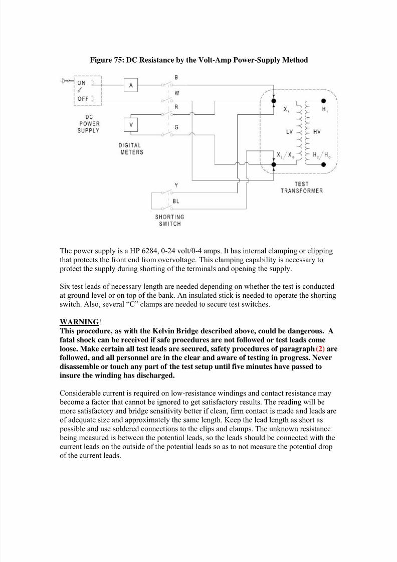
8/20/2019 SubstationCommissioning- Transformer Testing
http://slidepdf.com/reader/full/substationcommissioning-transformer-testing 64/83
Figure 75: DC Resistance by the Volt-Amp Power-Supply Method
The power supply is a HP 6284, 0-24 volt/0-4 amps. It has internal clamping or clipping
that protects the front end from overvoltage. This clamping capability is necessary to protect the supply during shorting of the terminals and opening the supply.
Six test leads of necessary length are needed depending on whether the test is conducted
at ground level or on top of the bank. An insulated stick is needed to operate the shortingswitch. Also, several “C” clamps are needed to secure test switches.
WARNING!
This procedure, as with the Kelvin Bridge described above, could be dangerous. A
fatal shock can be received if safe procedures are not followed or test leads come
loose. Make certain all test leads are secured, safety procedures of paragraph (2) are
followed, and all personnel are in the clear and aware of testing in progress. Never
disassemble or touch any part of the test setup until five minutes have passed to
insure the winding has discharged.
Considerable current is required on low-resistance windings and contact resistance may become a factor that cannot be ignored to get satisfactory results. The reading will be
more satisfactory and bridge sensitivity better if clean, firm contact is made and leads are
of adequate size and approximately the same length. Keep the lead length as short as
possible and use soldered connections to the clips and clamps. The unknown resistance being measured is between the potential leads, so the leads should be connected with the
current leads on the outside of the potential leads so as to not measure the potential drop
of the current leads.
8/20/2019 SubstationCommissioning- Transformer Testing
http://slidepdf.com/reader/full/substationcommissioning-transformer-testing 65/83
Four-terminal measurements of low resistance (<1 Ω) require the current and potentialtest leads to be attached to the top of the bushing terminal or the winding and not to the
bus or line that connects to the bushing. Do not disconnect leads while the DC source
switch is closed. An external voltmeter may be used to help determine whether or not the
winding is still being charged.
Procedure for Power Supply Method:
1. Connect the test setup as in Fig. 75 excepting power supply and voltmeter.
2. The power supply should be warned up for minimum of 30 minutes.
3. Connect test switches and test leads per the connection diagram except forleads to the DC power supply and voltmeter.
4. Turn on the DC power supply and allow it to warm up for 30 minutes. Once
the power supply has warmed up, turn the voltage control knob fully CCWand then rotate the current control knob CW until the white light goes out.
5. Insure that 120-VAC source for the DC power supply is stable anddependable.6. With no burden on power supply, rotate the coarse voltage control knob so
that the voltmeter (on the power supply) reads 25 volts. Then turn the coarse
current-control knob fully CCW.7. With power supply turned off, connect 0.5-ohm/10-watt resistor between +
(positive) and output terminals.
8. Turn on power supply and rotate coarse current-control knob until the
ammeter on the power supply reads 2.0 A. The power supply current andvoltage controls are now set and will need no further adjusting. Connect the
voltmeter to the output terminals and note whether the output voltage is steady(about 1.1 volts). If the voltage is unstable, the power supply is not fully
warmed up or the 120-VAC source is not stable enough. Note: Do not use a
voltage regulator ahead of the power supply because some regulators clip the60-Hz wave peaks; the Systron-Donner requires a perfect 60-Hz sine wave.
9. Turn off the power supply and complete wiring connections per Fig. 75.
Summary of DC Resistance Measurement Procedures
1. Observe all safety rules.
2. Measure winding temperature.3. Wheatstone Bridge (windings >1 Ω)
• Check condition of internal batteries• Adjust Galvanometer to reference null mark• Use test leads with 0.1 Ω or less
• Bridge test leads
• Make a low-resistance connection to bushing terminals
• Make temperature measurements of the winding• If applicable, operate the tap changer several times
• Measure bridge winding plus test-lead resistance
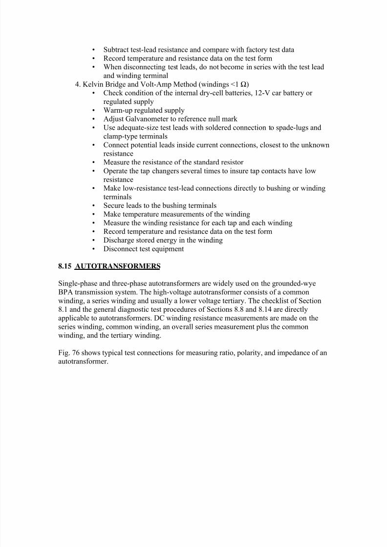
8/20/2019 SubstationCommissioning- Transformer Testing
http://slidepdf.com/reader/full/substationcommissioning-transformer-testing 66/83
• Subtract test-lead resistance and compare with factory test data
• Record temperature and resistance data on the test form• When disconnecting test leads, do not become in series with the test lead
and winding terminal
4. Kelvin Bridge and Volt-Amp Method (windings <1 Ω)
• Check condition of the internal dry-cell batteries, 12-V car battery orregulated supply
• Warm-up regulated supply• Adjust Galvanometer to reference null mark
• Use adequate-size test leads with soldered connection to spade-lugs and
clamp-type terminals
• Connect potential leads inside current connections, closest to the unknownresistance
• Measure the resistance of the standard resistor
• Operate the tap changers several times to insure tap contacts have lowresistance
• Make low-resistance test-lead connections directly to bushing or windingterminals• Secure leads to the bushing terminals
• Make temperature measurements of the winding
• Measure the winding resistance for each tap and each winding• Record temperature and resistance data on the test form
• Discharge stored energy in the winding
• Disconnect test equipment
8.15 AUTOTRANSFORMERS
Single-phase and three-phase autotransformers are widely used on the grounded-wye
BPA transmission system. The high-voltage autotransformer consists of a common
winding, a series winding and usually a lower voltage tertiary. The checklist of Section8.1 and the general diagnostic test procedures of Sections 8.8 and 8.14 are directly
applicable to autotransformers. DC winding resistance measurements are made on the
series winding, common winding, an overall series measurement plus the commonwinding, and the tertiary winding.
Fig. 76 shows typical test connections for measuring ratio, polarity, and impedance of anautotransformer.
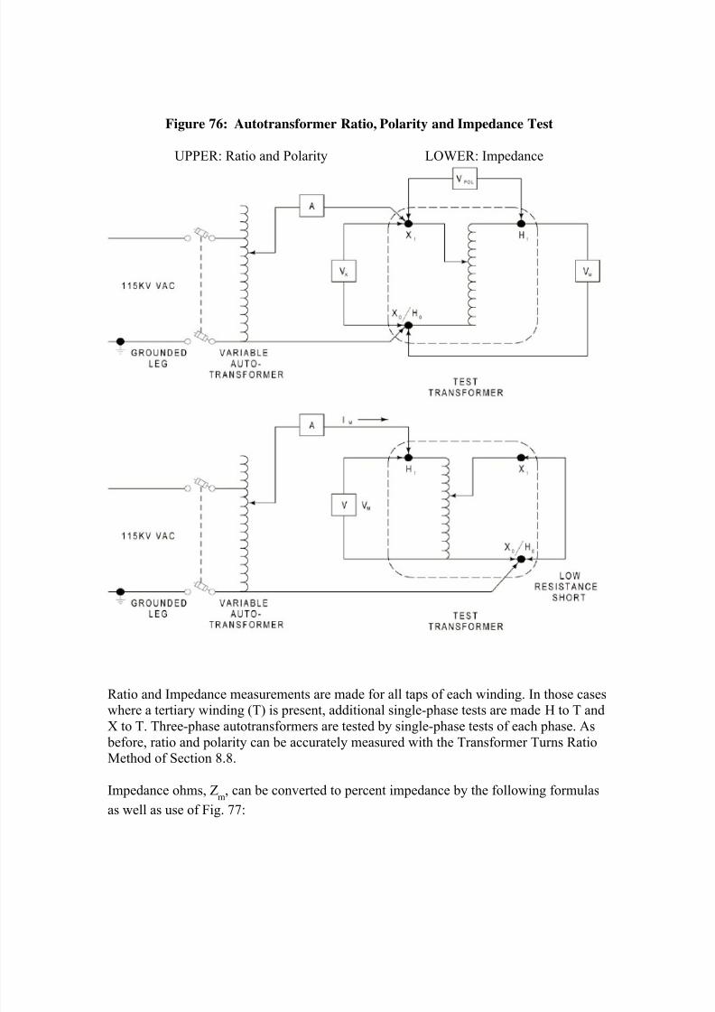
8/20/2019 SubstationCommissioning- Transformer Testing
http://slidepdf.com/reader/full/substationcommissioning-transformer-testing 67/83
Figure 76: Autotransformer Ratio, Polarity and Impedance Test
UPPER: Ratio and Polarity LOWER: Impedance
Ratio and Impedance measurements are made for all taps of each winding. In those cases
where a tertiary winding (T) is present, additional single-phase tests are made H to T andX to T. Three-phase autotransformers are tested by single-phase tests of each phase. As
before, ratio and polarity can be accurately measured with the Transformer Turns RatioMethod of Section 8.8.
Impedance ohms, Zm
, can be converted to percent impedance by the following formulas
as well as use of Fig. 77:
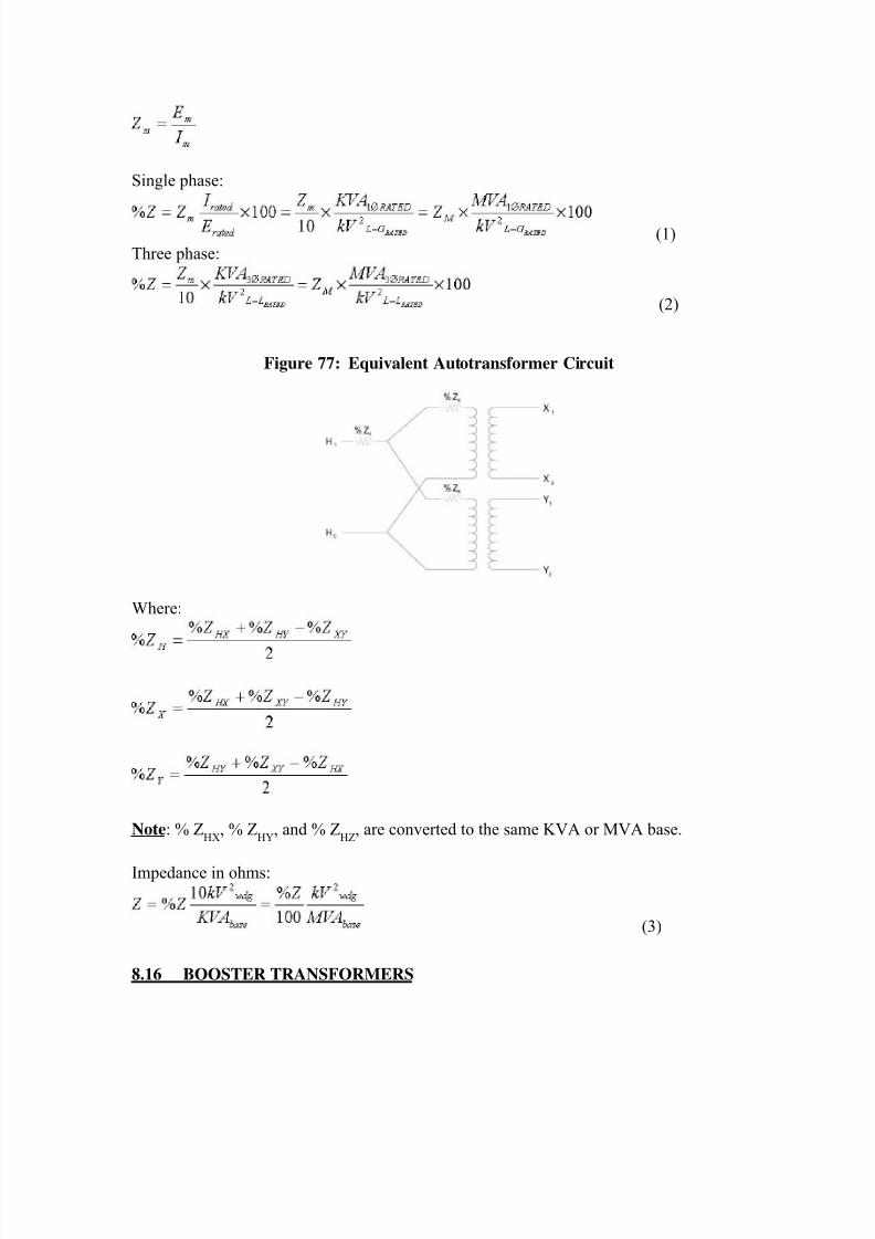
8/20/2019 SubstationCommissioning- Transformer Testing
http://slidepdf.com/reader/full/substationcommissioning-transformer-testing 68/83
Single phase:
(1)
Three phase:
(2)
Figure 77: Equivalent Autotransformer Circuit
Where:
Note: % ZHX
, % ZHY
, and % ZHZ
, are converted to the same KVA or MVA base.
Impedance in ohms:
(3)
8.16 BOOSTER TRANSFORMERS
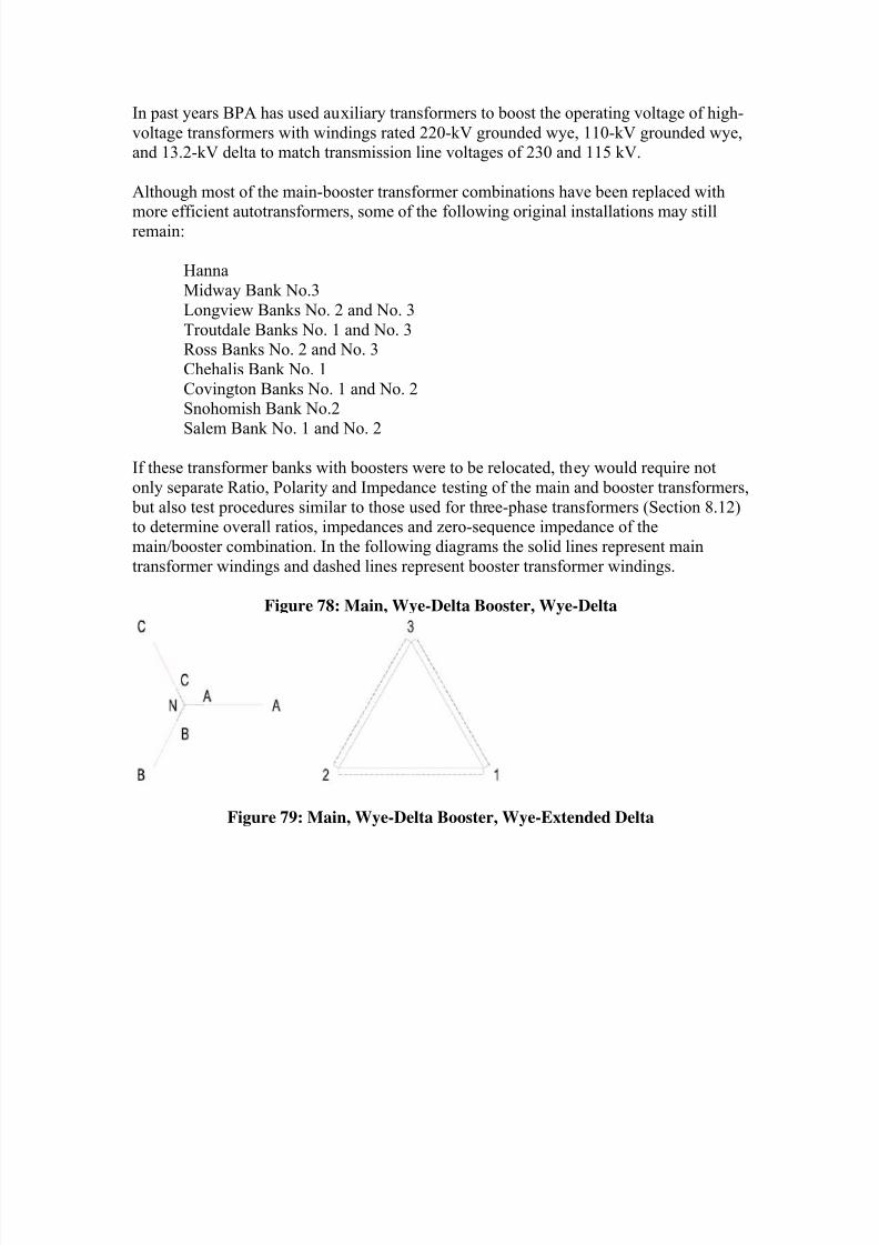
8/20/2019 SubstationCommissioning- Transformer Testing
http://slidepdf.com/reader/full/substationcommissioning-transformer-testing 69/83
In past years BPA has used auxiliary transformers to boost the operating voltage of high-
voltage transformers with windings rated 220-kV grounded wye, 110-kV grounded wye,and 13.2-kV delta to match transmission line voltages of 230 and 115 kV.
Although most of the main-booster transformer combinations have been replaced with
more efficient autotransformers, some of the following original installations may stillremain:
Hanna
Midway Bank No.3
Longview Banks No. 2 and No. 3
Troutdale Banks No. 1 and No. 3Ross Banks No. 2 and No. 3
Chehalis Bank No. 1
Covington Banks No. 1 and No. 2Snohomish Bank No.2
Salem Bank No. 1 and No. 2
If these transformer banks with boosters were to be relocated, they would require not
only separate Ratio, Polarity and Impedance testing of the main and booster transformers,
but also test procedures similar to those used for three-phase transformers (Section 8.12)to determine overall ratios, impedances and zero-sequence impedance of the
main/booster combination. In the following diagrams the solid lines represent main
transformer windings and dashed lines represent booster transformer windings.
Figure 78: Main, Wye-Delta Booster, Wye-Delta
Figure 79: Main, Wye-Delta Booster, Wye-Extended Delta
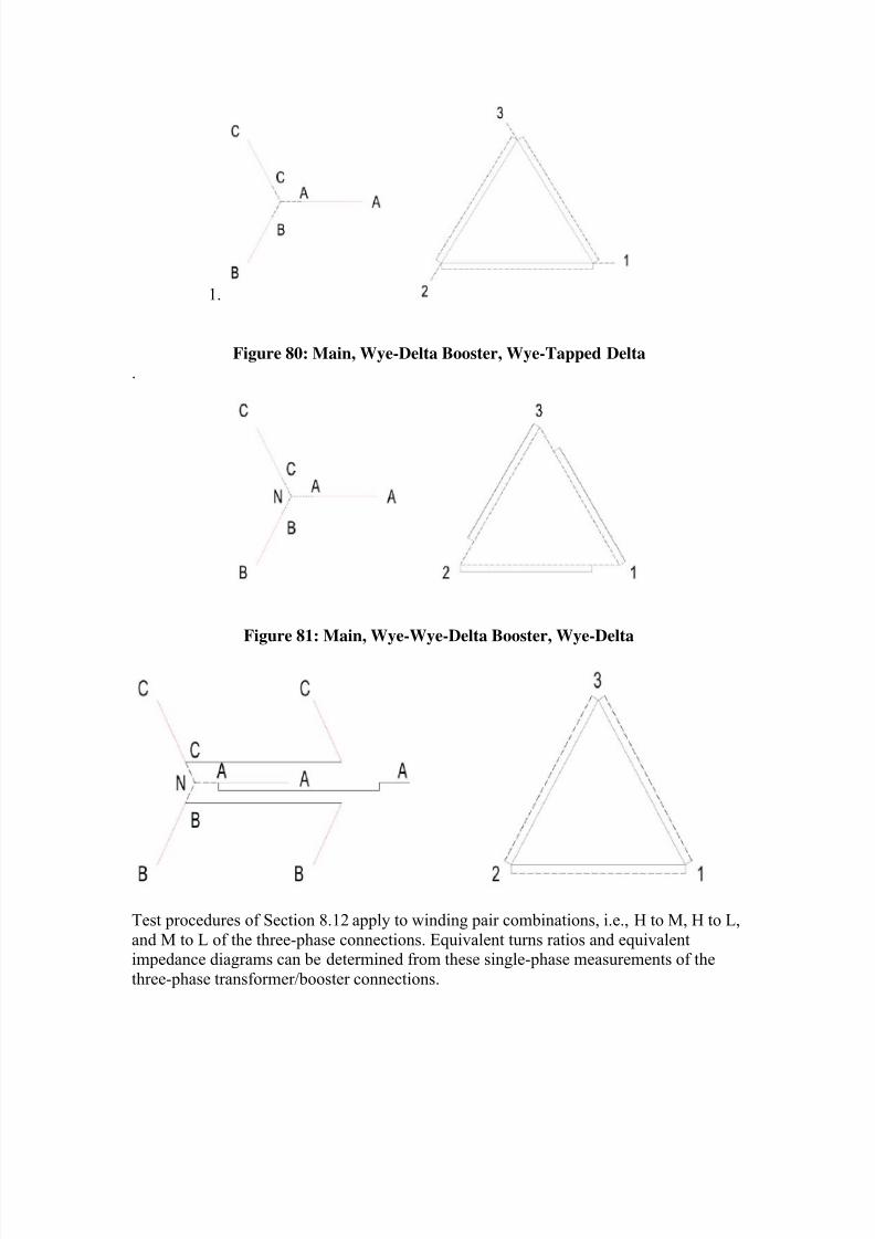
8/20/2019 SubstationCommissioning- Transformer Testing
http://slidepdf.com/reader/full/substationcommissioning-transformer-testing 70/83
1.
Figure 80: Main, Wye-Delta Booster, Wye-Tapped Delta
.
Figure 81: Main, Wye-Wye-Delta Booster, Wye-Delta
Test procedures of Section 8.12 apply to winding pair combinations, i.e., H to M, H to L,
and M to L of the three-phase connections. Equivalent turns ratios and equivalentimpedance diagrams can be determined from these single-phase measurements of the
three-phase transformer/booster connections.
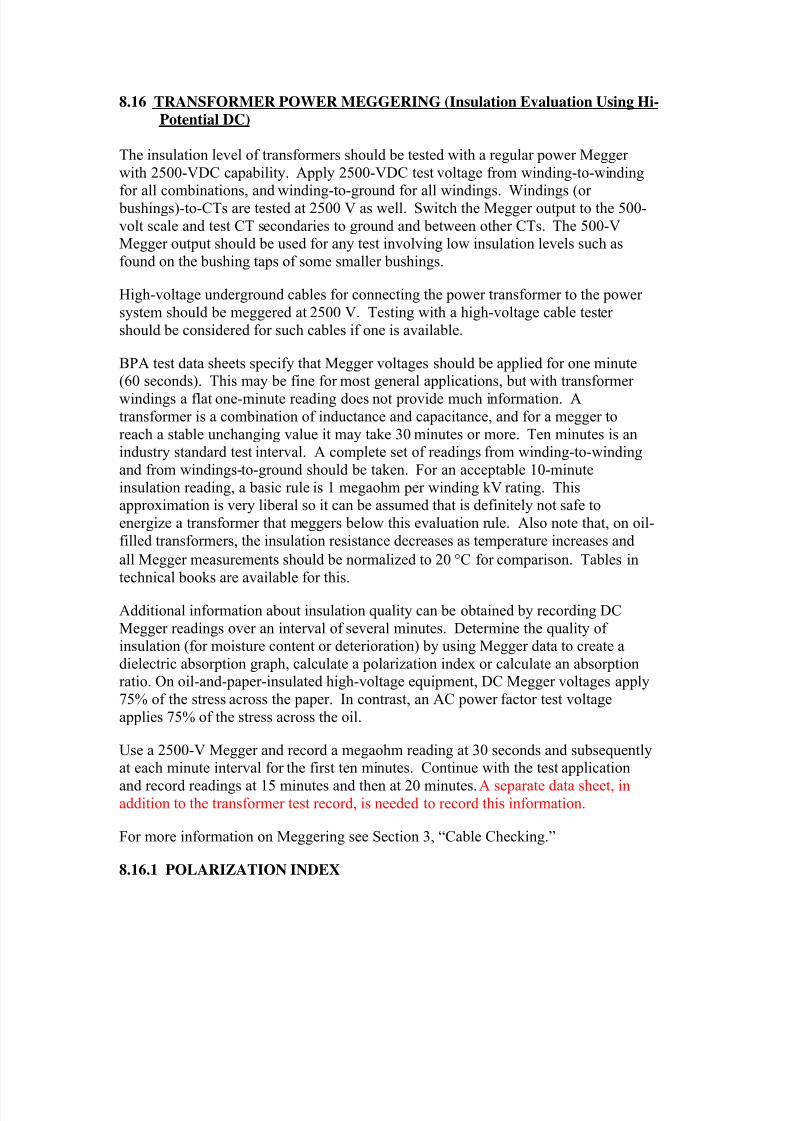
8/20/2019 SubstationCommissioning- Transformer Testing
http://slidepdf.com/reader/full/substationcommissioning-transformer-testing 71/83
8.16 TRANSFORMER POWER MEGGERING (Insulation Evaluation Using Hi-
Potential DC)
The insulation level of transformers should be tested with a regular power Megger
with 2500-VDC capability. Apply 2500-VDC test voltage from winding-to-winding
for all combinations, and winding-to-ground for all windings. Windings (or bushings)-to-CTs are tested at 2500 V as well. Switch the Megger output to the 500-
volt scale and test CT secondaries to ground and between other CTs. The 500-VMegger output should be used for any test involving low insulation levels such as
found on the bushing taps of some smaller bushings.
High-voltage underground cables for connecting the power transformer to the power
system should be meggered at 2500 V. Testing with a high-voltage cable tester
should be considered for such cables if one is available.
BPA test data sheets specify that Megger voltages should be applied for one minute(60 seconds). This may be fine for most general applications, but with transformer
windings a flat one-minute reading does not provide much information. A
transformer is a combination of inductance and capacitance, and for a megger to
reach a stable unchanging value it may take 30 minutes or more. Ten minutes is anindustry standard test interval. A complete set of readings from winding-to-winding
and from windings-to-ground should be taken. For an acceptable 10-minute
insulation reading, a basic rule is 1 megaohm per winding kV rating. Thisapproximation is very liberal so it can be assumed that is definitely not safe to
energize a transformer that meggers below this evaluation rule. Also note that, on oil-
filled transformers, the insulation resistance decreases as temperature increases and
all Megger measurements should be normalized to 20 C for comparison. Tables in
technical books are available for this.
Additional information about insulation quality can be obtained by recording DC
Megger readings over an interval of several minutes. Determine the quality ofinsulation (for moisture content or deterioration) by using Megger data to create a
dielectric absorption graph, calculate a polarization index or calculate an absorptionratio. On oil-and-paper-insulated high-voltage equipment, DC Megger voltages apply
75% of the stress across the paper. In contrast, an AC power factor test voltage
applies 75% of the stress across the oil.
Use a 2500-V Megger and record a megaohm reading at 30 seconds and subsequentlyat each minute interval for the first ten minutes. Continue with the test application
and record readings at 15 minutes and then at 20 minutes. A separate data sheet, inaddition to the transformer test record, is needed to record this information.
For more information on Meggering see Section 3, “Cable Checking.”
8.16.1 POLARIZATION INDEX
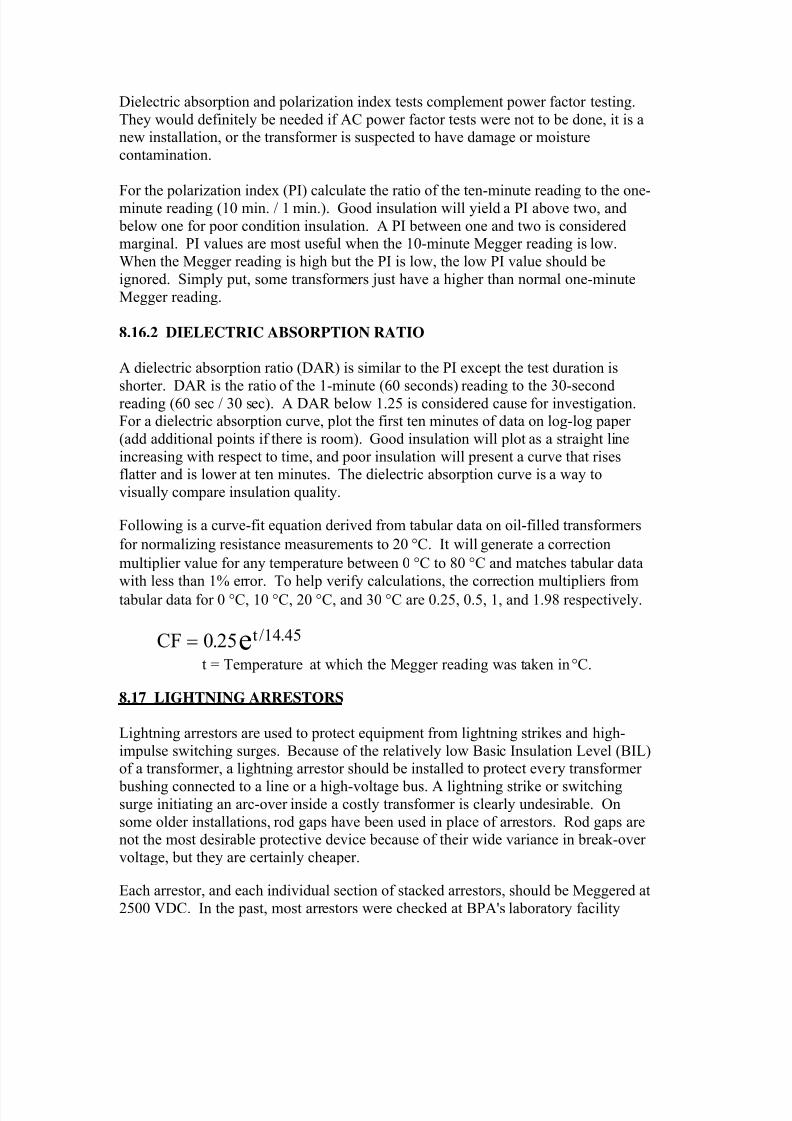
8/20/2019 SubstationCommissioning- Transformer Testing
http://slidepdf.com/reader/full/substationcommissioning-transformer-testing 72/83
Dielectric absorption and polarization index tests complement power factor testing.
They would definitely be needed if AC power factor tests were not to be done, it is anew installation, or the transformer is suspected to have damage or moisture
contamination.
For the polarization index (PI) calculate the ratio of the ten-minute reading to the one-minute reading (10 min. / 1 min.). Good insulation will yield a PI above two, and
below one for poor condition insulation. A PI between one and two is consideredmarginal. PI values are most useful when the 10-minute Megger reading is low.
When the Megger reading is high but the PI is low, the low PI value should be
ignored. Simply put, some transformers just have a higher than normal one-minute
Megger reading.
8.16.2 DIELECTRIC ABSORPTION RATIO
A dielectric absorption ratio (DAR) is similar to the PI except the test duration is
shorter. DAR is the ratio of the 1-minute (60 seconds) reading to the 30-secondreading (60 sec / 30 sec). A DAR below 1.25 is considered cause for investigation.For a dielectric absorption curve, plot the first ten minutes of data on log-log paper
(add additional points if there is room). Good insulation will plot as a straight line
increasing with respect to time, and poor insulation will present a curve that risesflatter and is lower at ten minutes. The dielectric absorption curve is a way to
visually compare insulation quality.
Following is a curve-fit equation derived from tabular data on oil-filled transformers
for normalizing resistance measurements to 20 C. It will generate a correction
multiplier value for any temperature between 0 C to 80 C and matches tabular data
with less than 1% error. To help verify calculations, the correction multipliers from
tabular data for 0 C, 10 C, 20 C, and 30 C are 0.25, 0.5, 1, and 1.98 respectively.
CF te 0 25 14 45. / .
t = Temperature at which the Megger reading was taken in C.
8.17 LIGHTNING ARRESTORS
Lightning arrestors are used to protect equipment from lightning strikes and high-
impulse switching surges. Because of the relatively low Basic Insulation Level (BIL)of a transformer, a lightning arrestor should be installed to protect every transformer
bushing connected to a line or a high-voltage bus. A lightning strike or switchingsurge initiating an arc-over inside a costly transformer is clearly undesirable. On
some older installations, rod gaps have been used in place of arrestors. Rod gaps arenot the most desirable protective device because of their wide variance in break-over
voltage, but they are certainly cheaper.
Each arrestor, and each individual section of stacked arrestors, should be Meggered at
2500 VDC. In the past, most arrestors were checked at BPA's laboratory facility
8/20/2019 SubstationCommissioning- Transformer Testing
http://slidepdf.com/reader/full/substationcommissioning-transformer-testing 73/83
prior to shipment. The Laboratory's present policy requires testing of arrestors having
nameplate ratings of 172 kV and above, all new types not previously used on the BPAsystem (regardless of their rating), and all new maintenance spares (minimum
emergency stock). BPA Laboratories should be contacted if problems or special tests
are required for lightning arrestors or Metal Oxide Voltage Limiters (MOVLs).
The nameplate kV rating for each arrestor should be verified to be sure it is the propersize for the application. Mismatching can occur, resulting in equipment failure and
outages. When stacked units are installed, the size and order of stacking should be
checked and compared with manufacturer's recommendations. Be sure to record
nameplate data from the installed arrestors.
Verify that hardware is properly provided or connected. For example, grading ringsshould be installed for arrestors 115 kV and above. All 500-kV and some 230-kV
arrestors must be mounted on proper standoff insulators, and ground conductor
connections must be present that assure electrical discharges will pass through the pulse counter (if outfitted with one). Eliminate extra ground path connections that
would prevent the counter from operating; arrestors have been installed with counters
shorted past. The standoff and ground side of the counter must be connected to the
station ground mat. This is usually done with 4/0 copper cable. Newer MOVLs arenot being installed with counters, in part because the MOVL clips electrical surges at
speeds that the counters cannot respond to predictably.
8.18 TEMPERATURE DEVICES
All large transformers have a temperature-indicating device of some type, and most
have temperature recorders as well. Indication may be for top-oil temperature or hot-
spot temperature. Additional temperature-sensing equipment may be installed to
provide alarm and control signals needed to activate automatic cooling systems.Indicator operation may be purely mechanical (tank-mounted temperature gauge or
thermometer), purely electrical (SCADA transducer & some chart recorders), or acombination of the two (chart recorder & multipoint temp recorder).
Temperature indicators, recorders, and controls must be functionally checked and
have their calibration verified. The most common method used in the past for
calibrating these devices was to immerse all heat sensor detector bulbs in a containerof oil, then heat the oil at a slow, constant rate. The oil-temperature changes were
measured with a temperature standard (thermometer), and readings for all devices
immersed in the oil were recorded simultaneously.
If alarm or control contacts are built into the devices, they must be set and checked
for the desired pickup point as the temperature is rising and for the proper dropout point as the temperature is falling. The typical contact dropout point should be 5 to
10 C lower than the pickup point. If the set point of a contact is changed, performthe temperature run again, starting at some point below the desired pickup value. The
desired point of contact pickup is dictated by System Operating Standards. A
8/20/2019 SubstationCommissioning- Transformer Testing
http://slidepdf.com/reader/full/substationcommissioning-transformer-testing 74/83
summary of recommended transformer cooling system alarm operating points can be
found in (see supplement listing) Operating Bulletin #15.
Capillary tubes for temperature detection devices must be handled carefully becausethey are fragile and cannot be repaired if damaged. Sharp bends should be avoided;
be aware that a kink or dent can disable the tube. The bulbs on the ends of these
capillary tubes fit into small wells at the top of the transformer tank. These wells areimmersed in the transformer oil reservoir. Their purpose is to provide isolation of the
internal environment from the external world. Designing transformers with oil wells
allows manipulating capillary tube bulbs without contaminating or draining the
transformer oil. Also, it would be difficult replacing defective temperature sensorswithout the existence of oil wells, because transformer tanks are usually slightly
pressurized by nitrogen gas or an oil-filled conservator tank. Be aware that some
temperature indicators on a transformer may not include an oil well, and creating anopening in the tank by removing those types would cause oil to gush out or nitrogen
pressure loss.
Proper calibration may be tedious, but it is very important. Temperature probes are
used to provide control signals for the automatic cooling system and to initiate alarm
signals when the transformer gets too hot. The temperature monitoring devices provide fundamental protection for the transformer -- preventing operation in an
overheated condition. If overheating occurs, a transformer's life expectancy is
reduced by the resulting insulation damage. Any time oil temperature exceeds 100
C (212 F), the paper insulating material is presumed to be deteriorating at an
accelerated rate (although there may be a few exceptions).
8.18.1 WINDING-TEMPERATURE DEVICES
Hot-spot or thermal-image devices are provided to represent the hottest point withinthe transformer while it is carrying load. Hot-spot temperature depends on I
2R losses
in the transformer windings, the rate at which heat transfers into the oil, and the rateat which the oil is cooled by ambient conditions surrounding the oil.
Temperatures indicated by a hot-spot thermometer, or a remote indicator connected to
a Resistive Temperature Device (RTD, or thermohm), are actually a product oftransformer top-oil temperature and the heat generated by oil-well heaters. Heater
current comes from a special bushing/low-iron CT of a single preselected ratio. The
CTs sole purpose is to provide load-proportional current for the hot-spot heaters. Inshort, hot-spot temperature indication is derived through a measurement of a
replicated (or model) temperature. The temperature is obtained this way becauseinsulation requirements and design constraints prevent measuring the actual
temperature of the windings directly. The replica temperature of the oil reservoirheats at the same rate as the oil surrounding the hottest spot in the transformer. The
current-driven heaters and their thermal characteristics are designed by the
manufacturer to follow heating characteristics derived from factory test data.
8/20/2019 SubstationCommissioning- Transformer Testing
http://slidepdf.com/reader/full/substationcommissioning-transformer-testing 75/83
For additional information, to obtain heating data on the actual winding, the factory
test circulates a high current through the transformer windings at low voltage. For thetests, temperature test probes are inserted at various points throughout the windings to
actually measure the hottest point at rated load current. During factory testing, some
points of interest cannot be measured physically without damaging the insulation, so
some test temperatures must be estimated from calculations using test data.
A hot-spot heater circuit can be verified functional by connecting the test equipment
as shown in the schematic diagram in Fig. 82. The test leads from the load box can
be connected directly in parallel to the output terminals of the hot-spot CT. It is not
necessary to disconnect the wires coming from this bushing CT, because the highreflected impedance of the open CT primary essentially causes test current to flow
only through the heater resistors.
A manufacturer's instruction book that includes characteristic time-
current/temperature curves, or graphs for the hot-spot heating devices, is helpful indetermining a starting point for the heat run. Such a graph is valuable for making
comparisons and verifying that heater-current adjustment settings are correct. The
heater tap is set at the factory and should not be changed or adjusted. The idea is not
to calibrate the heating of a hot-spot oil well, but to verify it is in working order. Iftest results are inconsistent with expectations, the most likely cause could be the test
equipment setup, method being used, or nonideal test conditions. Make sure the tests
are actually indicating defective equipment before claiming the equipment is suspect.
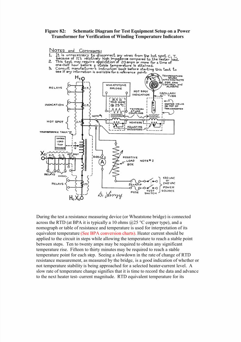
8/20/2019 SubstationCommissioning- Transformer Testing
http://slidepdf.com/reader/full/substationcommissioning-transformer-testing 76/83
Figure 82: Schematic Diagram for Test Equipment Setup on a Power
Transformer for Verification of Winding Temperature Indicators
During the test a resistance measuring device (or Wheatstone bridge) is connected
across the RTD (at BPA it is typically a 10 ohms @25 C copper type), and anomograph or table of resistance and temperature is used for interpretation of its
equivalent temperature (See BPA conversion charts). Heater current should be
applied to the circuit in steps while allowing the temperature to reach a stable point between steps. Ten to twenty amps may be required to obtain any significant
temperature rise. Fifteen to thirty minutes may be required to reach a stable
temperature point for each step. Seeing a slowdown in the rate of change of RTDresistance measurement, as measured by the bridge, is a good indication of whether or
not temperature stability is being approached for a selected heater-current level. A
slow rate of temperature change signifies that it is time to record the data and advance
to the next heater test- current magnitude. RTD equivalent temperature for its
8/20/2019 SubstationCommissioning- Transformer Testing
http://slidepdf.com/reader/full/substationcommissioning-transformer-testing 77/83
resistance should be simultaneously compared to that of the hot-spot-indicating
thermometer and/or chart recorder. The contact closing and opening temperatures ofthe hot-spot thermometer alarm/control contacts should be monitored and noted when
the transformer oil temperature reaches their pickup or dropout level.
Note that if the transformer is quite cold (10 C or less), injecting enough current intoits heater circuit to elevate the hot-spot well temperature to a level where the contacts
will close may be difficult if not impossible. To functionally check contact functions
when the outside temperature is quite low, the hot-spot thermometer contact arm may
have to be deflected manually to perform operational checks of the cooling or alarmcircuits. Use reason and good judgment here, and be careful not to apply too much
pressure to the operate arm.
CAUTION! A mechanical temperature movement can be damaged when manipulating itmanually. If much physical resistance to movement is present, it is better to just
bridge across the contacts with a test jumper when performing an electrical
control/alarm check.
A final check, after testing the heater(s) with AC current, is to verify that the CT is
actually terminated to it. Verify the connection is not open by simply measuring
across the same two terminals injected with AC current. If the CT is connected (andnot open-circuited), the ohmmeter will indicate close to zero ohms (and will be
significantly less than heater resistance). This is because the CT looks like a short
circuit to the DC ohmmeter (just the opposite of what it looks like to the AC quantityused to check the heaters). If a Current Ratio test can’t be done, flashing the hot-spot
CT will give further confidence that it is functional (See Section 5.3.13).
8.18.2 REMOTE TEMPERATURE INDICATION
There are generally two remote locations from which transformer temperatures aremonitored: at the substation control house and at the supervisory control center. Both
indications utilize 10-ohm thermohm RTDs mounted in the transformer as thetemperature reference source. The method for monitoring and interpreting this
information is quite different for each.
Temperature monitoring at the control house is typically done with a multipoint chart
recorder (Esterline Angus, Micromax, etc.) that prints numbered points on a chart
scaled in degrees centigrade ( 0C to 100C ). If a large three-phase transformer bank
is being monitored, there may be as many as nine individual RTD temperature pointsfor it on the chart. If a substation has two transformer banks, the temperatures may be
monitored by one recorder. Resolution problems occur when too many points are
being monitored and when several of the plotted points fall near the same
temperature. The time interval allowed between plotted points (printed numbers)determines how readable the chart is. To improve readability, it may be necessary to
change the recorder chart speed to lengthen the time between plotted points.
8/20/2019 SubstationCommissioning- Transformer Testing
http://slidepdf.com/reader/full/substationcommissioning-transformer-testing 78/83
One adjustment on the chart recorder that is important for transformer protection, is
the high temperature alarm point. The alarm set point of the recorder should beverified operational by sending alarm signals to both the local annunciator and
SCADA control. This can be done by moving the printing arm past the 90 C markwith the chart servo power turned off. The alarm point setting is determined by
operating standards published by a technical support branch of System Operations(See Supplement Listing).
As a side note, mechanically operated temperature recorders are becoming a thing of
the past due to the lack of support by manufacturers in the area of spare parts. Newrecorders, if installed, will probably be solid-state microprocessor-type devices. For
installations with bank temperature indication into SCADA the multipoint
temperature recorder may no longer be needed. Repair or replacement cost alongwith need will dictate whether worn-out recorders are replaced.
Transformer temperature indication for SCADA is normally provided by a transducer
wired to one of the bank thermohms (RTD). The substation temperature recorder and
SCADA transducer require their own individual thermohm resistors because theycannot be connected to use the same RTD. Temperature transducers are generally
precalibrated for the RTD in use but should be checked as part of SPC duties. The
transducer provides a calibrated milliamp output and the temperature scale is
determined by the value of the SCADA termination resistor. The transducer does not provide an alarm. A SCADA software temperature limit provides an alarm for
transformers being monitored by the control center. The high temperature alarm is
derived from the bank temperature quantity using the SCADA equipment software atthe control center. A quick check on proper indication is to verify that the SCADA
operator reads the same temperatures as the transformer temperature chart recorder
indication (or temperature indicated by another RTD). Remote temperature
indication cannot be compared with the top-oil thermometer unless the transformerhas been operating without load, because SCADA indication is a hot-spottemperature.
8.19 AUXILIARY POWER
Transformers that require continuous or cycled forced air and/or oil cooling systems
to maintain safe operating temperatures require an external power source. Cooling-system power may be provided from the station service supply, at the substation, or
by a customer source. More than one power source is required to provide cooling-
system backup for the loss of main source power.
Some installations have auxiliary or station-service transformers dedicated to
obtaining cooling power from local sources that are not directly compatible. Thesesmall transformers, used for cooling-system power, should also be tested in
accordance with the Section 3, “How to Test Voltage Transformers (VTs) and Small
Transformers”.
8.20 AUTOMATIC TRANSFER SWITCHES
8/20/2019 SubstationCommissioning- Transformer Testing
http://slidepdf.com/reader/full/substationcommissioning-transformer-testing 79/83
Transformers that require continuous cooling by auxiliary pumps and fans must besupported by two independent power sources to ensure transformer service when the
primary source fails. Many large transformers are rated for an operating time of one
hour or less without having their cooling fans and pumps in operation. When two
power sources are provided to feed one critical circuit, an automatic transfer switch isusually provided and may have controls at the transformer. Automatic transfer
switches often have alarm and indication points that should be verified to be inworking order.
As with all electrical components of a power system, wiring and functional operationof these switches must be checked. This includes a check for proper phase rotation of
three-phase sources and ties. A phase-rotation check must be made for all power
sources feeding the transfer switch. Fans and pumps don't provide cooling ifoperating in reverse. Proper operation of the transfer switch should be observed by
killing the source voltages, then re-energizing them in various sequences to assure
that everything functions as expected.
8.21 COOLING SYSTEM
Setting and testing the control devices of the cooling system equipment for proper
operation ensures reliable operation and long service life for transformers. The long-
term operation of transformer cooling systems are usually quite stable and troublefree if the cooler controls have been checked and set properly. It is easiest to “work
out the bugs” during the initial installation and testing of a transformer, because there
is basically unrestricted access for manipulation of cooling controls. Once atransformer has been placed in service and released to System Operations, it may be
difficult to get transformer coolers out of service except for an actual failure.
Because troubleshooting and repair require understanding how the system works,SPC and substation maintenance personnel should utilize T&E opportunities to obtain
familiarity with cooling controls.
For new installations, standard wiring and component checks, terminal tightening,
and Meggering should be performed prior to applying control power. The pre-energization checkout for power and cooling systems is not overly complicated. As
soon as the operating controls can be powered up, all manual and automatic control
functions should be verified. Often, the temperature at which the hot-spot controlthermometer contacts operate the automatic controller can be verified by manually
advancing the indicating arm of the thermometer until the contact initiates the cooling
controller or initiates an alarm (as long as care is taken not to damage it). Do notmove the thermometer arm if much force is necessary (as would be when the oil
temperature is very low). If the arm is bent, recalibration of the device may be
required. For a very cold transformer, or to be on the safe side, a jumper across the
contact terminals will suffice.
If remote indicating devices are provided at the control house to signal operation ofthe cooling system or its components, verify operation for both the cooling system
8/20/2019 SubstationCommissioning- Transformer Testing
http://slidepdf.com/reader/full/substationcommissioning-transformer-testing 80/83
and the temperature indicators. Check alarms for loss of cooling or other
temperature-related troubles during this process. Inspect all fans and pumps whileoperating to observe their direction of rotation. This requires observation of oil and
airflows for each individual unit to assure none are turning in reverse.
8.22 BUSHING-POTENTIAL DEVICES
Potential devices may be mounted on transformer bushings where the accuracy of
voltage transformers is not required and where the installation of VTs would not be
cost effective.
Point-to-point wiring, torque of screws and terminal tightness, and meggering of
insulation are required checks. The high-voltage probe that supplies the bushing tapvoltage to the potential device should be meggered at 2500 VDC.
For a more detailed description of potential-device testing refer to Section 6,“Instrument Potential Transformers (VTs).”
8.23 AUXILIARY PROTECTION EQUIPMENT
Various types of auxiliary alarm, indication, and protection equipment are also foundon transformers. The amount and type of auxiliary equipment provided depends on
the size of, and who manufactured, the transformer.
Pressure relief is necessary for all transformer main tanks and UL tap-changer tanks.
Each tank is completely separate and has its own relief. Pressure reliefs are usually
outfitted with mechanically operated lever arms and can be manually tripped andreset to verify proper alarm contact operation. A screwdriver or other tool may be
required for the operation and reset of these alarm switches. Don't forget to reset aftertesting. A pressure-relief device initiates an alarm, but does not initiate circuit breaker tripping to clear the transformer from the power system.
Oil-level indicators are provided on nearly every type of oil-insulated electrical
equipment (transformers included). The oil level should be checked for every tank
and every bushing on the transformer before energization. Functional operation oftransformer main-tank and tap-changer oil-level indicating devices must be checked
before the units have been filled with oil. The construction crew is responsible for
checking oil-level indicators during transformer assembly. If a transformer is fullyassembled, it must be assumed that these gauges have been tested and were indicating
accurately before final assembly. Most external indicating gauges are mechanicallyattached to a float inside the tank; however, some gauges are magnetically coupled.If a magnetically coupled indicator is used, a strong magnet can be used external to
the tank to check its operation. In some cases, connecting a jumper across the wires
at the exit point from the tank may be the only way to test the alarm. Oil-levelindicators are typically used to provide alarm signals only, but in some installations
they may actually be wired to trip the lockout relay to de-energize the transformer.
8/20/2019 SubstationCommissioning- Transformer Testing
http://slidepdf.com/reader/full/substationcommissioning-transformer-testing 81/83
8.23.1 BUCHHOLTZ RELAYS
Buchholtz Relays (or equivalent sudden-pressure relays) are installed on many of the
large transformers to provide alarm and tripping capability. This relay operates for
two different types of action within the transformer tank. The first, which producesthe fastest reaction, is a response to sudden pressure changes such as those that would
occur if a transformer were to have an internal electrical fault. A contact device
attached to a pressure-sensitive gate is connected to trip the transformer's lockoutauxiliary relay (LOR). The lockout relay's function is to trip and lockout the control
of all circuit breakers associated with the transformer. It trips all bank PCBs and
prevents all breaker closures, either locally or remotely, until an inspection can bemade and the LOR is reset by hand. Instantaneous isolation of the transformer from
the power system for internal faults is desirable. In addition to being a sudden-
pressure relay, a Buchholtz relay includes a secondary feature. Secondary action,which is much slower than sudden-pressure action, occurs as a result of gas
accumulation inside the relay. Gas production is generally caused by corona
discharge within the transformer, which causes the oil to break down into
combustible gases. The rate at which gas accumulation occurs dictates whether analarm, trip, or both are initiated. A Buchholtz Relay usually has a tube running down
the side of the transformer and is terminated with a shutoff valve, which allows a
sample of any gas produced to be collected for laboratory analysis.
Most Buchholtz Relays have levers or buttons to test their operation. Other modelsmay require that dry air or nitrogen be forced through them to perform a test. This
second method can be tedious and requires a manufacturer's instruction book to
facilitate the test.
8.23.2 BASIC SUDDEN PRESSURE RELAYS
Basic Sudden Pressure Relays (SPR), like the G.E.-type J, have been mounted onmany transformers not outfitted with Buchholtz Relays. There was a time in the past
when the type-J relays were very unreliable and falsely tripped due to mechanical
shock to the relay itself, for example, hitting the transformer tank. Sometimes theywould false trip from pressure changes within the transformer not due to an actual
transformer fault (such as a fault close to the substation). This problem has been
resolved by using an improved version of the SPR and by adding auxiliary time-delay
or overcurrent fault-detecting relays to the tripping circuits of existing installations.
Type-J relays can be tested by simulating differential pressure through the followingmethods: (1) opening an oil cap on the side of the relay; (2) bleeding a small amount
of oil; (3) closing the oil cap; and (4) opening the main valve. Note: To perform anoperational check, close the main valve between the SPR and the main tank before
opening the bleeder vent on the SPR. Otherwise, a spectacular geyser of oil will gush
forth from the bleed vent when it is opened. Once the oil is bled off through the bleeder vent, close it off. Then open the main valve to the SPR. The sudden inrush
of oil should be sufficient to operate the SPR.
8/20/2019 SubstationCommissioning- Transformer Testing
http://slidepdf.com/reader/full/substationcommissioning-transformer-testing 82/83
CAUTION! Do not open the relay bleeder cap on an energized transformer that is carrying load
unless the protective relay tripping circuits have been disabled. At BPA, this is
normally done by pulling the trip switch on the Lockout Auxiliary Relay.
8.23.3 OUT-OF-STEP ALARM SCHEME
Transformer installations with three individual phases and UL tap changers will have
an out-of-step alarm scheme. The purpose of this alarm is to tell the substation or
SCADA operators that one or two of the tap changers have not operated properly.The tap-changer operating mechanism is outfitted with two sets of cams that are
either open or closed on alternate tap positions. One set of the even/odd cams is
wired in series with the operate coil of a time-delay relay (Agastat, etc.). Test thisalarm by placing one of the three tap changers one tap position off from the other
two. A major concern for correct indication is the pick-up and drop-out adjustment of
the time-delay relay. When a local or remote change is initiated, it takes time for allthe tap changers to move to the next tap position. The out-of-step alarm delay time
must be long enough to allow all three tap changers to reach the next tap without
initiating an alarm. Proper operation of this scheme must be verified from both the
substation and SCADA. Although it is unlikely that the tap changer will be foundmore than one position out of step, reasonable care should be given to checking the
operation of this scheme because an alarm would only be sent for cases where one tap
is off by an odd number of possible positions. No alarm would be initiated if the tap
changers were off by an even number of steps. For example, A could be on "3", B
on "5", and C on "7" and still not initiate an alarm because they are all off position by two steps (an even number).
The other set of odd/even cams may be utilized to prevent operation of all three tap
changers when any phase is out of step with the other two. This serves as an interlockscheme to prevent remote operation of the tap changers until all phases have been
adjusted to the identical tap. One reason for not operating the transformers out of stepis that it causes system voltage and current imbalance. An out-of-step condition can
also cause severe circulating currents between phases and results in undesirable
transformer heating and possibly overload.
In addition to the alarms for tap changers, loss of tap-changer DC control power, loss
of AC power, and all other special function alarms should be checked by trippingtheir ACBs or operating the control devices associated with each alarm.
8.24 OVERALL LOADING
CT circuits for transformers should be loaded overall before the transformer is placed
in service. For an assembled transformer, injection of high current into the CT primary for purposes of overall loading is impossible with the available test
equipment. A simulated current needs to be injected at the cable termination point for
each CT secondary in the individual transformer terminal cabinet. A return path is
8/20/2019 SubstationCommissioning- Transformer Testing
http://slidepdf.com/reader/full/substationcommissioning-transformer-testing 83/83
needed for this injected current from the insertion points of the control house relays,
so that magnitude and polarity can be verified. Spare cable wires are usuallyavailable for this purpose, which typically requires two people.
For more details on overall loading, see Section 5.3.9.
8.25 TRIP CHECKS
Trip checks verify that a transformer can be removed from service for various kinds
of trouble. Verifying the trip function may be critical to the longevity of atransformer. Checks from devices that monitor slow-developing problems, that do
not require immediately removing a transformer from service (such as overheating
due to loss of cooling), may not seem critical, but they are. Even though aconsiderable time delay is allowable, the service life of a transformer would be
reduced if it didn’t eventually trip. For severe internal problems, such as a flashover
or fault within the windings, instantaneous de-energization of the transformer isimperative to prevent irreparable damage and possible explosion or fire. For this
reason, special relays are often used with the larger transformers to provide the fastest
means of fault detection available to clear the faulted equipment from service.
Protective relay schemes for transformers may involve relays including sudden
pressure, differential-overcurrent, phase-overcurrent, neutral-overcurrent, tertiary-overcurrent, delta-winding ground detector, and even distance relays or transfer trip.
These relays make up a protective package and often include auxiliary relays of
various kinds to provide additional flexibility in operating the transformer. The person responsible for T&E of the transformer should verify that required trip checks
have been made. The tripping capability from every contact of every protective
device should be checked prior to placing the equipment in service. For transformers
where more than one circuit breaker must be tripped to clear the transformer,auxiliary tripping Lock Out Relays (LORs) are required. Auxiliary relays are used to provide multiple contacts for tripping, isolation, and alarms, because protective relays
often do not provide more than one contact for each type of trouble they monitor.
Auxiliaries also provide isolation between control circuits, and can supply contacts
with much higher current-interrupting capacities than those of protective relays. The breaker doesn’t have to operate from every device, only the devices that trip it
directly. For example, once the PCB tripping paths from the LOR have been verified,
unnecessary operations of the PCB can be avoided by tripping only the lockout relay(at BPA, with the PCB trip blades open on the LOR test switch).