Embed Size (px)
DESCRIPTION
commisioning
Citation preview
25/11/2013 Testing and Commissioning of Current Transformer | EEP
electrical-engineering-portal.com/testing-commissioning-current-transformer 1/16
66Share Tweet 21 21
Testing and Commissioning of Current
Transformer
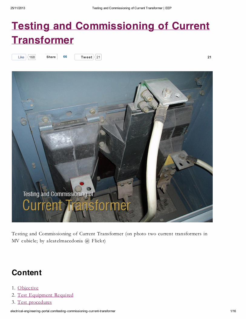
Testing and Commissioning of Current Transformer (on photo two current transformers in
MV cubicle; by a lcatelmacedonia @ Flickr)
Content
1. Objective
2. Test Equipment Required
3. Test procedures
Like 168
25/11/2013 Testing and Commissioning of Current Transformer | EEP
electrical-engineering-portal.com/testing-commissioning-current-transformer 2/16
1. Mechanical Check and Visual Inspection
2. Insulation Resistance Test
3. Polarity Test
4. Secondary/Loop Resistance Test
5. Burden Test (optional test)
6. Magnetization Curve Test (optional test)
7. Turns Ratio Test (optional test)
8. Primary Injection Test
9. High Voltage Test
10. Commisioning Test
4. Applicable Standards
5. Live VIDEO CT Testing (6 Testings)
1. Objective
To confirm the physical condition and electrical characterist ics of current transformer installed in the
instal lation. Ensure the CT is connected to system properly in a ll respect (primary and secondary) .
2. Test Equipment Required
Required equipment for testing:
1. Insulation tester
2. Polarity tester
3. Digita l low ohmmeter
4. Current source, multimeter
5. Variac, step-up transformer (0-2kv)
6. Primary current injection set
Go to Content ↑
3. Test Procedures
3.1. Mechanical Check and Visual Inspection
1. Verify nameplate ratings are in accordance with the approved drawings and specifications.
25/11/2013 Testing and Commissioning of Current Transformer | EEP
electrical-engineering-portal.com/testing-commissioning-current-transformer 3/16
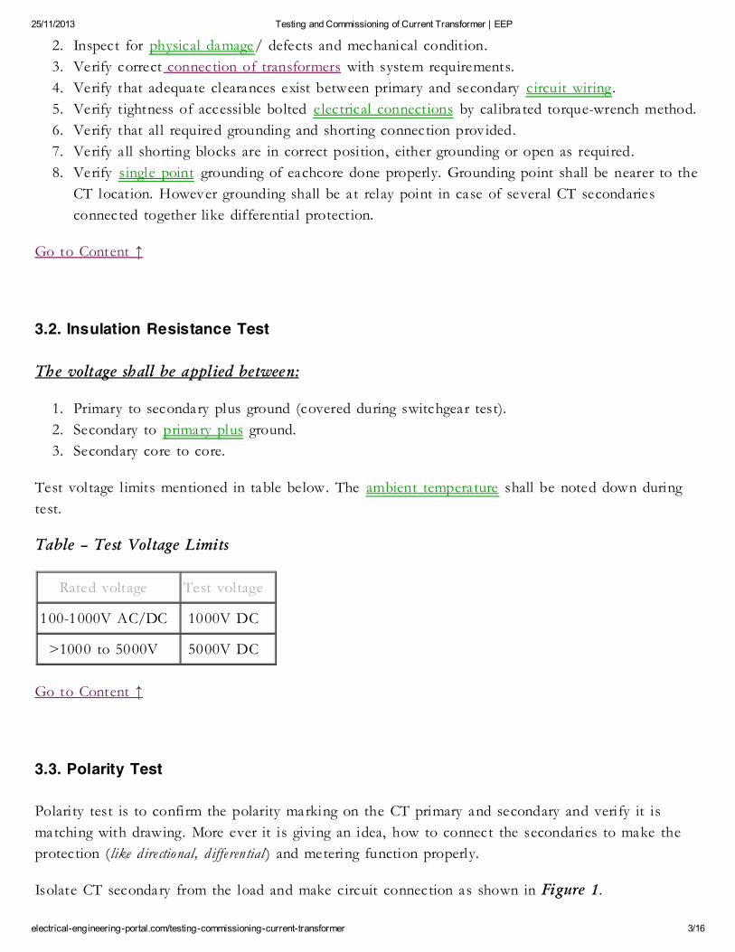
2. Inspect for physical damage/ defects and mechanical condit ion.
3. Verify correct connection of transformers with system requirements.
4. Verify that adequate clearances exist between primary and secondary circuit wiring.
5. Verify t ightness of accessible bolted electrical connections by cal ibrated torque-wrench method.
6. Verify that al l required grounding and shorting connection provided.
7. Verify a ll shorting blocks are in correct position, either grounding or open as required.
8. Verify single point grounding of eachcore done properly. Grounding point shall be nearer to the
CT location. However grounding shall be at relay point in case of several CT secondaries
connected together like differentia l protection.
Go to Content ↑
3.2. Insulation Resistance Test
The voltage shall be applied between:
1. Primary to secondary plus ground (covered during switchgear test).
2. Secondary to primary plus ground.
3. Secondary core to core.
Test voltage l imits mentioned in table below. The ambient temperature shall be noted down during
test.
Table – Test Voltage Limits
Rated voltage Test voltage
100-1000V AC/DC 1000V DC
>1000 to 5000V 5000V DC
Go to Content ↑
3.3. Polarity Test
Polarity test is to confirm the polarity marking on the CT primary and secondary and verify it is
matching with drawing. More ever it is giving an idea, how to connect the secondaries to make the
protection (like d irectional, d ifferential ) and metering function properly.
Isolate CT secondary from the load and make circuit connection as shown in Figure 1.
25/11/2013 Testing and Commissioning of Current Transformer | EEP
electrical-engineering-portal.com/testing-commissioning-current-transformer 4/16
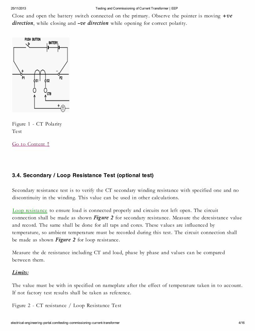
Close and open the battery switch connected on the primary. Observe the pointer is moving +ve
direction, while closing and –ve direction while opening for correct polarity.
Figure 1 - CT Polarity
Test
Go to Content ↑
3.4. Secondary / Loop Resistance Test (optional test)
Secondary resistance test is to verify the CT secondary winding resistance with specified one and no
discontinuity in the winding. This value can be used in other calculations.
Loop resistance to ensure load is connected properly and circuits not left open. The circuit
connection shall be made as shown Figure 2 for secondary resistance. Measure the dcresistance value
and record. The same shal l be done for al l taps and cores. These values are influenced by
temperature, so ambient temperature must be recorded during this test . The circuit connection shall
be made as shown Figure 2 for loop resistance.
Measure the dc resistance including CT and load, phase by phase and values can be compared
between them.
Limits:
The value must be with in specified on nameplate after the effect of temperature taken in to account.
If not factory test results shall be taken as reference.
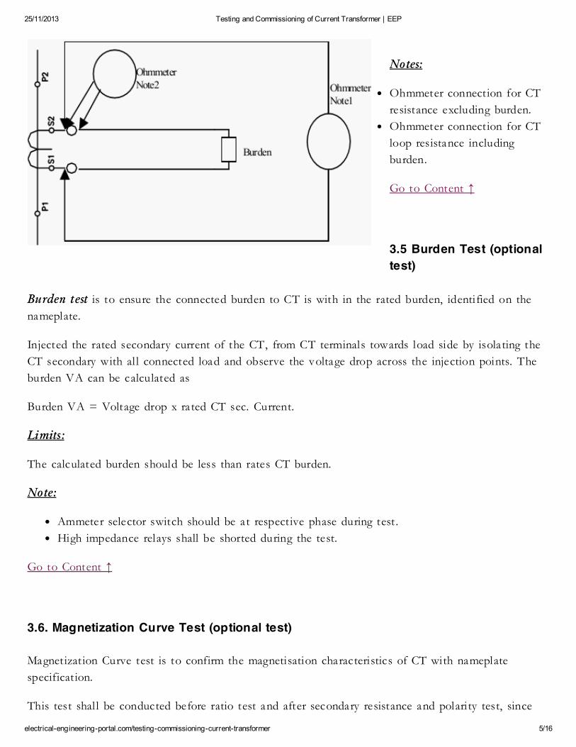
Figure 2 - CT resistance / Loop Resistance Test
25/11/2013 Testing and Commissioning of Current Transformer | EEP
electrical-engineering-portal.com/testing-commissioning-current-transformer 5/16
Notes:
Ohmmeter connection for CT
resistance excluding burden.
Ohmmeter connection for CT
loop resistance including
burden.
Go to Content ↑
3.5 Burden Test (optional
test)
Burden test is to ensure the connected burden to CT is with in the rated burden, identified on the
nameplate.
Injected the rated secondary current of the CT, from CT terminals towards load side by isolating the
CT secondary with al l connected load and observe the voltage drop across the injection points. The
burden VA can be calculated as
Burden VA = Voltage drop x rated CT sec. Current.
Limits:
The calculated burden should be less than rates CT burden.
Note:
Ammeter selector switch should be at respective phase during test .
High impedance relays shall be shorted during the test.
Go to Content ↑
3.6. Magnetization Curve Test (optional test)
Magnetization Curve test is to confirm the magnetisation characteristics of CT with nameplate
specification.
This test shal l be conducted before ratio test and after secondary resistance and polarity test, since
25/11/2013 Testing and Commissioning of Current Transformer | EEP
electrical-engineering-portal.com/testing-commissioning-current-transformer 6/16
residual magnetism left in the core due to DC test (polarity, resistance), which leads additional error
in ratio test. The meters used for this test shall be having true RMS measurement.
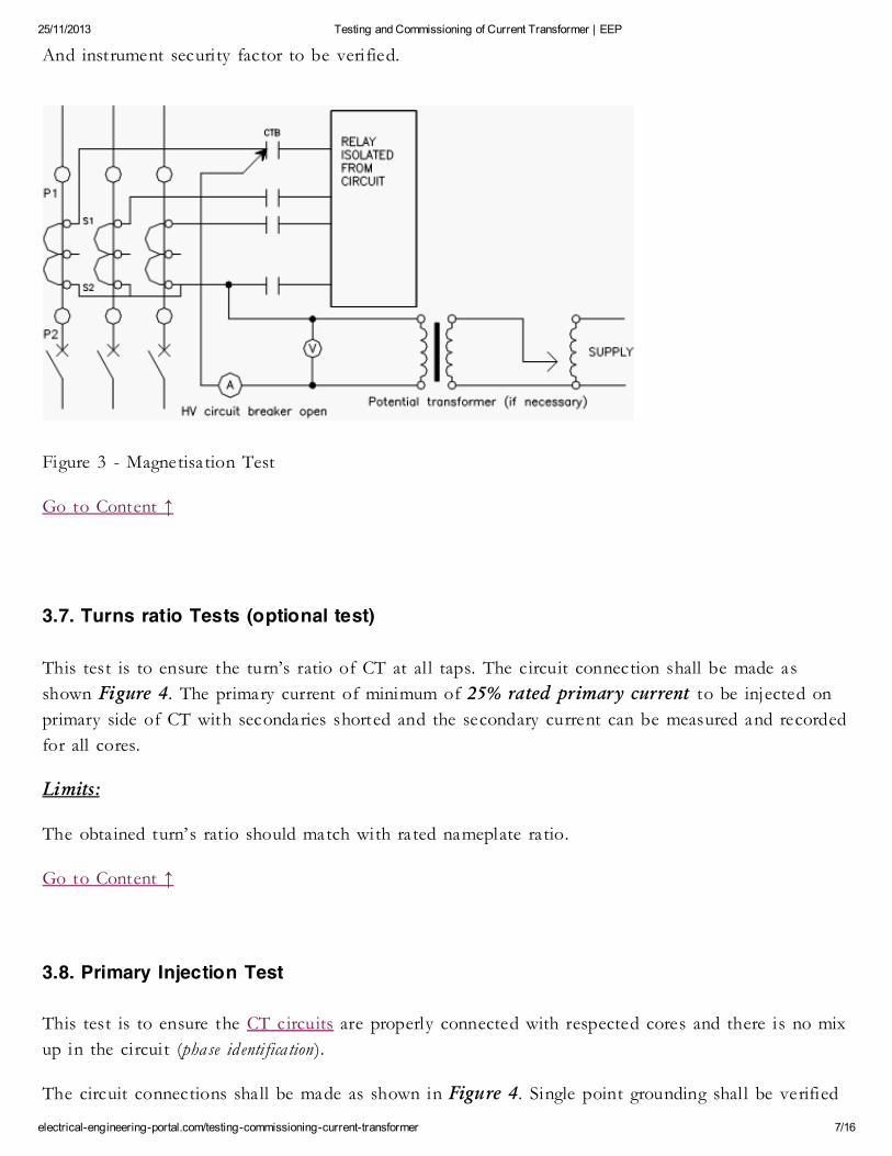
The circuit connection shal l be made as shown Figure 3. The primary should be open during test .
Demagnetisation
Before start the test demagnetise the core by Inject voltage on secondary terminals and increase up to
where considerable increment in current with small voltage increment. Now start decreasing the
voltage to zero, the rate at which increased.
Magnetisation test
Now increase the voltage and monitor the excitation current up to the CT reaching near to saturation
point. Record the reading of voltage and current at severa l points. Plot the curve and evaluate the Vk
and Img from the graph.
Limits:
Class X CT:
The obta ined Vk should be greater than specified one; mag current should be less than specified one.
Protection class CT:
The secondary limiting voltage can be calculated as follow:
Vslv = Is * ALF (Rct + (VA/Is*Is))
Where:
Is – rated secondary current
Rct – CT secondary resistance
VA – rated CT burden
ALF – Accuracy l imit factor
The mag current (Img) drawn at Vslv can be obta ined from graph. The following criteria should be
satisfied.
Img < accuracy class * ALF * Is
Metering Class CT:
Accuracy can be ensured as follow:
Img at Vs (= 1.2 * VA / Is) should be less than (accuracy class * Is)
25/11/2013 Testing and Commissioning of Current Transformer | EEP
electrical-engineering-portal.com/testing-commissioning-current-transformer 7/16
And instrument security factor to be verified.
Figure 3 - Magnetisation Test
Go to Content ↑
3.7. Turns ratio Tests (optional test)
This test is to ensure the turn’s ratio of CT at al l taps. The circuit connection shall be made as
shown Figure 4. The primary current of minimum of 25% rated primary current to be injected on
primary side of CT with secondaries shorted and the secondary current can be measured and recorded
for all cores.
Limits:
The obta ined turn’s rat io should match with rated nameplate ratio.
Go to Content ↑
3.8. Primary Injection Test
This test is to ensure the CT circuits are properly connected with respected cores and there is no mix
up in the circuit (phase id enti fica tion).
The circuit connections shall be made as shown in Figure 4. Single point grounding shal l be verified
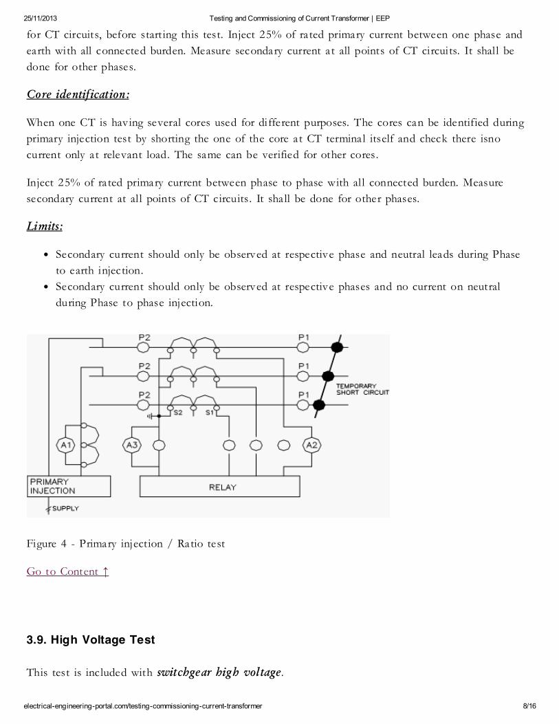
25/11/2013 Testing and Commissioning of Current Transformer | EEP
electrical-engineering-portal.com/testing-commissioning-current-transformer 8/16
for CT circuits, before start ing this test. Inject 25% of rated primary current between one phase and
earth with all connected burden. Measure secondary current at all points of CT circuits. It shal l be
done for other phases.
Core identification:
When one CT is having several cores used for different purposes. The cores can be identified during
primary injection test by shorting the one of the core at CT terminal itself and check there isno
current only at relevant load. The same can be verified for other cores.
Inject 25% of rated primary current between phase to phase with al l connected burden. Measure
secondary current at al l points of CT circuits. It shall be done for other phases.
Limits:
Secondary current should only be observed at respective phase and neutral leads during Phase
to earth injection.
Secondary current should only be observed at respective phases and no current on neutral
during Phase to phase injection.
Figure 4 - Primary injection / Ratio test
Go to Content ↑
3.9. High Voltage Test
This test is included with switchgear high voltage.
25/11/2013 Testing and Commissioning of Current Transformer | EEP
electrical-engineering-portal.com/testing-commissioning-current-transformer 9/16
Objective of HV test is to determine the equipment is in propercondit ion to put in service, after
instal lation for which it was designed and to give some basis for predicting whether or not that a
healthy condition wil l remain or if deterioration is underway which can result in abnormally short l ife.
Test Instruments Required for HV Test
Calibrated AC hi-pot test set for switchgear with leakage current indicator and overload protection.
Calibrated DC hi-pot test set for cables with leakage current indicator and overload protection.
Go to Content ↑
3.10. Commisioning Test
After commissioning, secondary current measurement shall be carried out in CT circuits. Phase angle
check shall be done for correct direction. Go to Content ↑
4. Applicable Standards
IEC 60044-1: Instrument transformers – current transformer.
IEC 60694: common specifications for HV switchgear.
Go to Content ↑
5. Live VIDEO CT Testing (6 Testings)
1. CT Tests – Ratio and Polarity
25/11/2013 Testing and Commissioning of Current Transformer | EEP
electrical-engineering-portal.com/testing-commissioning-current-transformer 10/16
Dear Valuable Customer, Your requested site is blocked by PTA. Please consult PTA if you have any query regarding
requested site Visit=?
Ca nt see t his vi deo? C lick here t o watch it on Youtu be.
2. CT Tests – Burden Secondary Side
25/11/2013 Testing and Commissioning of Current Transformer | EEP
electrical-engineering-portal.com/testing-commissioning-current-transformer 11/16
Ca nt see t his vi deo? C lick here t o watch it on Youtu be.
3. CT Tests – Excitation Curve
25/11/2013 Testing and Commissioning of Current Transformer | EEP
electrical-engineering-portal.com/testing-commissioning-current-transformer 12/16
The connection was reset.
Ca nt see t his vi deo? C lick here t o watch it on Youtu be.
4. CT Tests – Winding or Burden Resistance
25/11/2013 Testing and Commissioning of Current Transformer | EEP
electrical-engineering-portal.com/testing-commissioning-current-transformer 13/16
Ca nt see t his vi deo? C lick here t o watch it on Youtu be.
5. CT Tests – Voltage Withstand Test
Related Searches:
Electr ical And
Electronic
Engineering
Institution Of
Electr ical
Engineers
Generate Pow er
Electr ical
Engineering
Handbook
?
25/11/2013 Testing and Commissioning of Current Transformer | EEP
electrical-engineering-portal.com/testing-commissioning-current-transformer 14/16
Ca nt see t his vi deo? C lick here t o watch it on Youtu be.
6. CT Tests – Polarity By Pulses
25/11/2013 Testing and Commissioning of Current Transformer | EEP
electrical-engineering-portal.com/testing-commissioning-current-transformer 15/16
Ca nt see t his vi deo? C lick here t o watch it on Youtu be.
Resource: Testing and Commissioning o f Electri cal Equipment – Schneider Electric Servi ce Dpt.
Recommended EE articles
Edvard - Electrica l engineer, programmer and founder of EEP. Highly special ized for design of LV
high power busbar trunking (<6300A) in power substations, buildings and industry fascili ties.
Designing of LV/MV switchgears. Professional in AutoCAD programming and web-design. Developer
of awsome electrical design software ePlusMenuCAD. Present on Google+.

25/11/2013 Testing and Commissioning of Current Transformer | EEP
electrical-engineering-portal.com/testing-commissioning-current-transformer 16/16
© 2013 EEP - Electrica l Engineering Porta l. All Rights Reserved | Privacy Policy | 43 queries in
0.955 seconds.
Powered by CsanyiGroup
Become EEP's Contributor and introduce yourself to 70k+ of our readers al l across
the web.
CATCH US ON ≡ FacebookLinkedInTwitterGoogle+RSS
RECOMMENDED ≡ 21 Safety Rules for Working with Electrica l Equipment
TOP
Get