Embed Size (px)
Citation preview

Doc. 0093790 rev E
Page � of �8
GN ReSound as Global Technical Operations
gto.gnresound.comLautrupbjerg 9 • DK-2750 Ballerup • Denmark
E-mail: [email protected]
Technical Manual Pixel BTEPL70-D/DI/DV/DVIPL80-DVI
Doc. 0093790 rev E
Page 2 of �8
Table of contents
Spare parts .................................................................................................................... 3-�0Electronic housing assembly ........................................................................................��-�2On-off mechanism .............................................................................................................�3Final assembly............................................................................................................. �4-�5Replacement of microphones ............................................................................................�6Test fixture ................................................................................................................... �7-�8
Doc. 0093790 rev E
Page 3 of �8
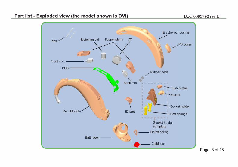
Part list - Exploded view (the model shown is DVI)
PCB
Front mic.
Back mic.
SuspensionsPins Listening coil VC
Rubber pads
Batt.springs
Socket
Push-button
Socket holdercomplete
Socket holderID-part
Batt. door
Rec. Module
Electronic housing
PB cover
On/off spring
Child lock
Doc. 0093790 rev E
Page 4 of �8
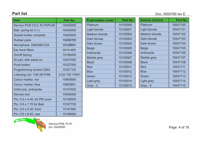
Item Part No.Service PCB C3.0, PL70/PL80 �5429200Batt. spring kit (+/-) �5429300Socket holder complete �5429400Rubber pads �5456700Microphone EM4368-C54 �0�2860�Ear hook filters 04�4-469On/off Spring �5�68400ID part, with serial no. �5437400Push-button �5327000Programming socket CS44 �5327�00Listening coil Y29-36-FHM 3�22 �50 7454�Colour marker, red �5665800Colour marker, blue �566580�Child lock, anthracite �5�67602Service tool �5506500Pin, 0.5 x 4.40, for PB cover �5�56000Pin, 0.6 x 7.70 for Batt. �5�67700Pin, 0.6 x 5.20, front �5�67900Pin, 0.6 x 8.50, rear �5�68000
Push-button cover Part No.Platinum �5�55900Light blonde �5�5590�Medium blonde �5�55902Dark blonde �5�55903Dark brown �5�55904Beige �5�55905Anthracite �5�55906Marble grey �5�55907Black �5�55908Red �5�559��Blue �5�559�2Green �5�559�3Light grey �5�559�4Grey - 2 �5�559�5
Service PCB, PL70 p/n �5429200
Part listVolume Control Part No.Platinum �6547�00Light blonde �6547�0�Medium blonde �6547�02Dark blonde �6547�03Dark brown �6547�04Beige �6547�05Anthracite �6547�06Marble grey �6547�07Black �6547�08Red �6547���Blue �6547��2Green �6547��3Light grey �6547��4Grey - 2 �6547��5
Doc. 0093790 rev E
Page 5 of �8
Part list
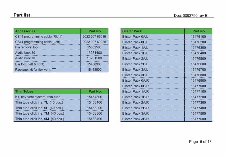
Accessories : Part No.CS44 programming cable (Right) 9022 907 690�9
CS44 programming cable (Left) 9022 907 69029
Pin removal tool �5502500
Audio boot 80 �623�400Audio boot 70 �623�500
Ear Box (left & right) �5458900
Package, kit for flex vent, TT �5468500
Blister Pack Part No.Blister Pack 0A/L �5476�00Blister Pack 0B/L �5476200Blister Pack �A/L �5476300Blister Pack �B/L �5476400Blister Pack 2A/L �5476500Blister Pack 2B/L �5476600Blister Pack 3A/L �5476700Blister Pack 3B/L �5476800Blister Pack 0A/R �5476900Blister Pack 0B/R �5477000Blister Pack �A/R �5477�00Blister Pack �B/R �5477200Blister Pack 2A/R �5477300Blister Pack 2B/R �5477400Blister Pack 3A/R �5477500Blister Pack 3B/R �5477600
Thin Tubes Part No.Kit, flex vent system, thin tube �5467800Thin tube click ins, 7L (40 pcs.) �5468�00Thin tube click ins, 9L (40 pcs.) �5468200Thin tube click ins, 7M (40 pcs.) �5468300Thin tube click ins, 9M (40 pcs.) �5468400
Doc. 0093790 rev E
Page 6 of �8
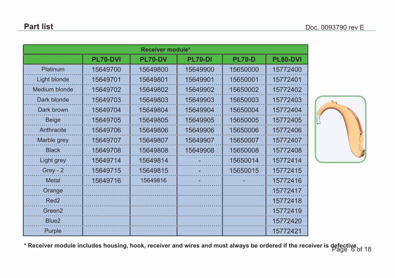
Part list
Receiver module*PL70-DVI PL70-DV PL70-DI PL70-D PL80-DVI
Platinum �5649700 �5649800 �5649900 �5650000 �5772400Light blonde �564970� �564980� �564990� �565000� �577240�
Medium blonde �5649702 �5649802 �5649902 �5650002 �5772402Dark blonde �5649703 �5649803 �5649903 �5650003 �5772403Dark brown �5649704 �5649804 �5649904 �5650004 �5772404
Beige �5649705 �5649805 �5649905 �5650005 �5772405Anthracite �5649706 �5649806 �5649906 �5650006 �5772406
Marble grey �5649707 �5649807 �5649907 �5650007 �5772407Black �5649708 �5649808 �5649908 �5650008 �5772408
Light grey �56497�4 �56498�4 - �56500�4 �57724�4Grey - 2 �56497�5 �56498�5 - �56500�5 �57724�5
Metal �56497�6 �56498�6 - - �57724�6Orange �57724�7Red2 �57724�8
Green2 �57724�9Blue2 �5772420Purple �577242�
* Receiver module includes housing, hook, receiver and wires and must always be ordered if the receiver is defective.
Doc. 0093790 rev E
Page 7 of �8
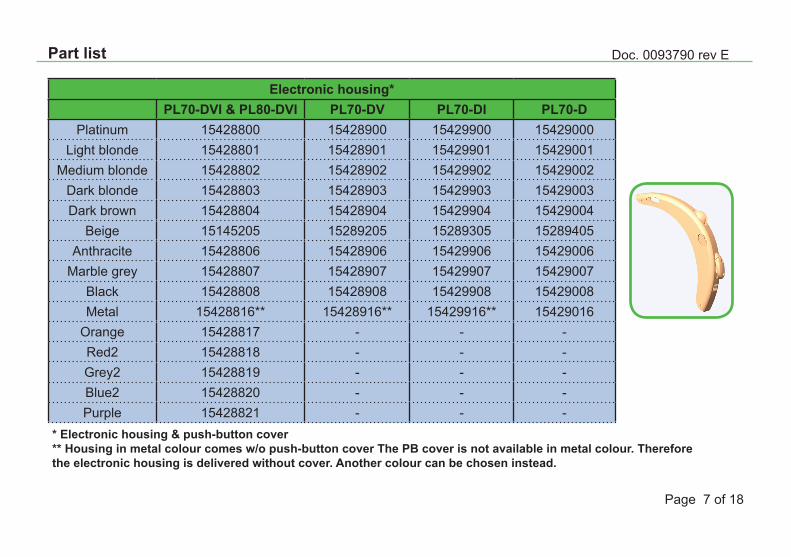
Part list
Electronic housing*PL70-DVI & PL80-DVI PL70-DV PL70-DI PL70-D
Platinum �5428800 �5428900 �5429900 �5429000Light blonde �542880� �542890� �542990� �542900�
Medium blonde �5428802 �5428902 �5429902 �5429002Dark blonde �5428803 �5428903 �5429903 �5429003Dark brown �5428804 �5428904 �5429904 �5429004
Beige �5�45205 �5289205 �5289305 �5289405Anthracite �5428806 �5428906 �5429906 �5429006
Marble grey �5428807 �5428907 �5429907 �5429007Black �5428808 �5428908 �5429908 �5429008Metal �54288�6** �54289�6** �54299�6** �54290�6
Orange �54288�7 - - -Red2 �54288�8 - - -Grey2 �54288�9 - - -Blue2 �5428820 - - -Purple �542882� - - -
* Electronic housing & push-button cover** Housing in metal colour comes w/o push-button cover The PB cover is not available in metal colour. Therefore the electronic housing is delivered without cover. Another colour can be chosen instead.
Doc. 0093790 rev E
Page 8 of �8
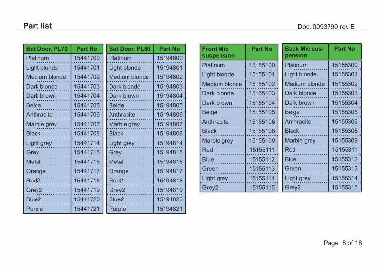
Part list
Bat Door, PL70 Part NoPlatinum �544�700Light blonde �544�70�Medium blonde �544�702Dark blonde �544�703Dark brown �544�704Beige �544�705Anthracite �544�706Marble grey �544�707Black �544�708Light grey �544�7�4Grey �544�7�5Metal �544�7�6Orange �544�7�7Red2 �544�7�8Grey2 �544�7�9Blue2 �544�720Purple �544�72�
Bat Door, PL80 Part NoPlatinum �5�94800Light blonde �5�9480�Medium blonde �5�94802Dark blonde �5�94803Dark brown �5�94804Beige �5�94805Anthracite �5�94806Marble grey �5�94807Black �5�94808Light grey �5�948�4Grey �5�948�5Metal �5�948�6Orange �5�948�7Red2 �5�948�8Grey2 �5�948�9Blue2 �5�94820Purple �5�9482�
Front Mic suspension
Part No
Platinum �5�55�00Light blonde �5�55�0�Medium blonde �5�55�02Dark blonde �5�55�03Dark brown �5�55�04Beige �5�55�05Anthracite �5�55�06Black �5�55�08Marble grey �5�55�09Red �5�55���Blue �5�55��2Green �5�55��3Light grey �5�55��4Grey2 �5�55��5
Back Mic sus-pension
Part No
Platinum �5�55300Light blonde �5�5530�Medium blonde �5�55302Dark blonde �5�55303Dark brown �5�55304Beige �5�55305Anthracite �5�55306Black �5�55308Marble grey �5�55309Red �5�553��Blue �5�553�2Green �5�553�3Light grey �5�553�4Grey2 �5�553�5
Doc. 0093790 rev E
Page 9 of �8
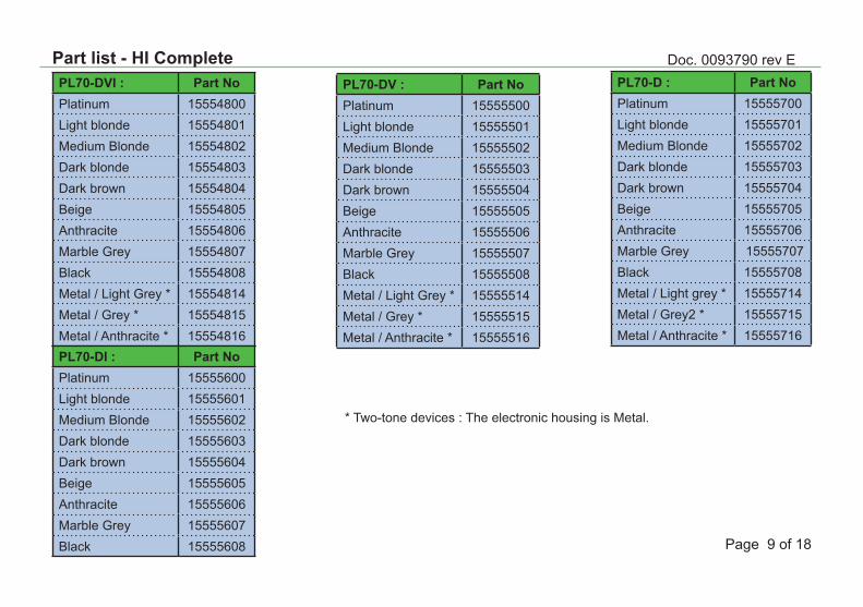
Part list - HI CompletePL70-DVI : Part NoPlatinum �5554800Light blonde �555480�Medium Blonde �5554802Dark blonde �5554803Dark brown �5554804Beige �5554805Anthracite �5554806Marble Grey �5554807Black �5554808Metal / Light Grey * �55548�4Metal / Grey * �55548�5Metal / Anthracite * �55548�6
* Two-tone devices : The electronic housing is Metal.
PL70-DI : Part NoPlatinum �5555600Light blonde �555560�Medium Blonde �5555602Dark blonde �5555603Dark brown �5555604Beige �5555605Anthracite �5555606Marble Grey �5555607Black �5555608
PL70-DV : Part NoPlatinum �5555500Light blonde �555550�Medium Blonde �5555502Dark blonde �5555503Dark brown �5555504Beige �5555505Anthracite �5555506Marble Grey �5555507Black �5555508Metal / Light Grey * �55555�4Metal / Grey * �55555�5Metal / Anthracite * �55555�6
PL70-D : Part NoPlatinum �5555700Light blonde �555570�Medium Blonde �5555702Dark blonde �5555703Dark brown �5555704Beige �5555705Anthracite �5555706Marble Grey �5555707Black �5555708Metal / Light grey * �55557�4Metal / Grey2 * �55557�5Metal / Anthracite * �55557�6
Doc. 0093790 rev E
Page �0 of �8
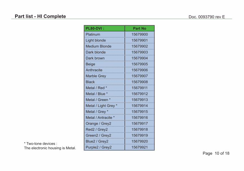
Part list - HI Complete
PL80-DVI : Part NoPlatinum �5679900Light blonde �567990�Medium Blonde �5679902Dark blonde �5679903Dark brown �5679904Beige �5679905Anthracite �5679906Marble Grey �5679907Black �5679908Metal / Red * �56799��Metal / Blue * �56799�2Metal / Green * �56799�3Metal / Light Grey * �56799�4Metal / Grey * �56799�5Metal / Antracite * �56799�6Orange / Grey2 �56799�7Red2 / Grey2 �56799�8Green2 / Grey2 �56799�9Blue2 / Grey2 �5679920Purple2 / Grey2 �567992�
* Two-tone devices : The electronic housing is Metal.
Doc. 0093790 rev E
Page �� of �8
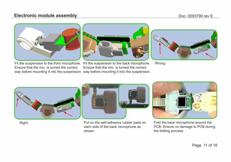
Electronic module assembly
Right.
Fit the suspension to the front microphone.Ensure that the mic. is turned the correct way before mounting it into the suspension.
Fit the suspension to the back microphone.Ensure that the mic. is turned the correct way before mounting it into the suspension.
Wrong.
Fold the back microphone around thePCB. Ensure no damage to PCB duringthe folding process.
Put on the self-adhesive rubber pads oneach side of the back microphone as shown.
PICTURE
Doc. 0093790 rev E
Page �2 of �8
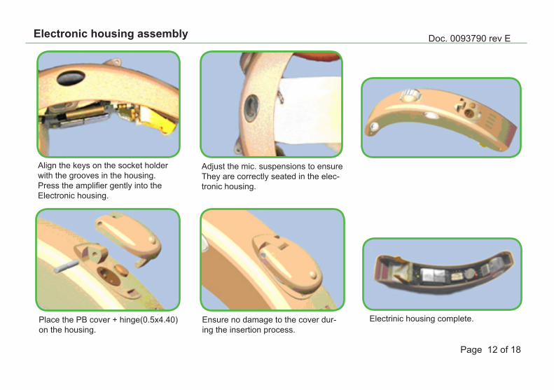
Electronic housing assembly
Align the keys on the socket holder with the grooves in the housing. Press the amplifier gently into theElectronic housing.
Adjust the mic. suspensions to ensure They are correctly seated in the elec-tronic housing.
Place the PB cover + hinge(0.5x4.40) on the housing.
Ensure no damage to the cover dur-ing the insertion process.
Electrinic housing complete.

Doc. 0093790 rev E
Page �3 of �8
On-off mechanism
Connect the electronic housing to the receiver module and fix them with the pins (except the rear pin). Mount the on/off spring into the receiver module and fix it with the rear pin.
Rear pin
Doc. 0093790 rev E
Page �4 of �8
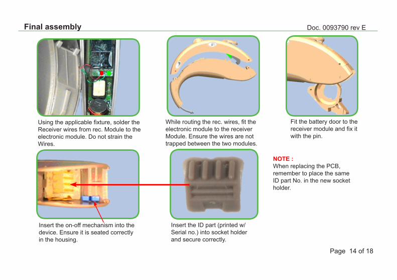
NOTE :When replacing the PCB,remember to place the sameID part No. in the new socketholder.
Using the applicable fixture, solder theReceiver wires from rec. Module to the electronic module. Do not strain theWires.
While routing the rec. wires, fit the electronic module to the receiverModule. Ensure the wires are not trapped between the two modules.
Fit the battery door to the receiver module and fix it with the pin.
Insert the on-off mechanism into the device. Ensure it is seated correctly in the housing.
Insert the ID part (printed w/Serial no.) into socket holder and secure correctly.
Final assembly
Doc. 0093790 rev E
Page �5 of �8
Final assembly
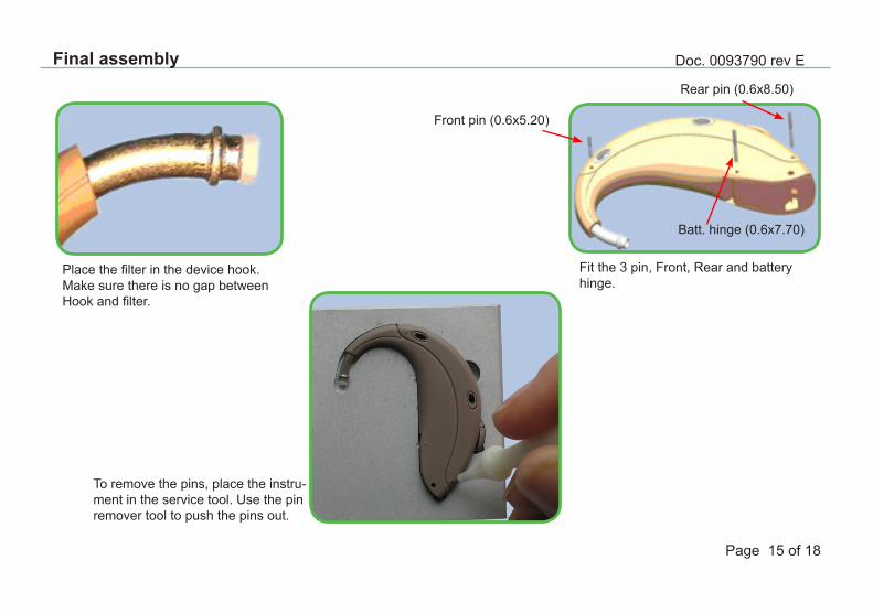
Place the filter in the device hook.Make sure there is no gap betweenHook and filter.
Rear pin (0.6x8.50)
Fit the 3 pin, Front, Rear and battery hinge.
Front pin (0.6x5.20)
Batt. hinge (0.6x7.70)
To remove the pins, place the instru-ment in the service tool. Use the pinremover tool to push the pins out.
Doc. 0093790 rev E
Page �6 of �8
Replacement of microphones
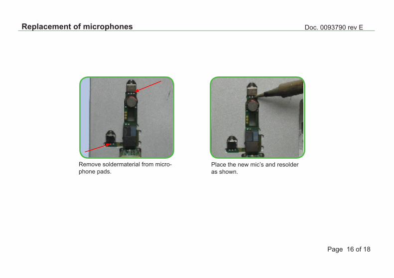
Remove soldermaterial from micro-phone pads.
Place the new mic’s and resolderas shown.
Doc. 0093790 rev E
Page �7 of �8
Test
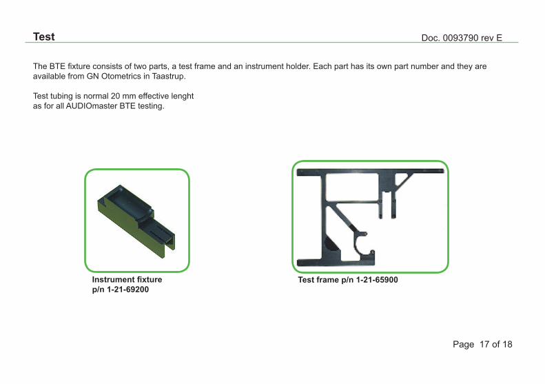
The BTE fixture consists of two parts, a test frame and an instrument holder. Each part has its own part number and they areavailable from GN Otometrics in Taastrup.
Test tubing is normal 20 mm effective lenghtas for all AUDIOmaster BTE testing.
Instrument fixture p/n 1-21-69200
Test frame p/n 1-21-65900
Doc. 0093790 rev E
Page �8 of �8
Test
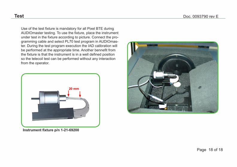
Use of the test fixture is mandatory for all Pixel BTE during AUDIOmaster testing. To use the fixture, place the instrument under test in the fixture according to picture. Connect the pro-gramming cable and select PL70 test program in AUDIOmas-ter. During the test program execution the IAD calibration will be performed at the appropriate time. Another bennefit from the fixture is that the instrument is in a well defined position so the telecoil test can be performed without any interaction from the operator.
20 mm
Instrument fixture p/n 1-21-69200