Embed Size (px)
Citation preview

Technical ManualReSound MATCH BTE, PBTE & SPBTE
Global Technical Operations gto.gnresound.com
Lautrupbjerg 7 • DK-2750 Ballerup • DenmarkE-mail: [email protected]
Doc 0166440 rev. E
Page 2 of 19
Table of Contents
MATCH 70/80:
Description...........................................................................................................................3Exploded View .....................................................................................................................4Part List ........................................................................................................................... 5-7HI Disassembly....................................................................................................................8Replacing Parts ............................................................................................................. 9-10Test Equipment ..................................................................................................................11
MATCH 90:
Description.........................................................................................................................12Part List .............................................................................................................................13Part List - CROS/BICROS .................................................................................................14HI Disassembly..................................................................................................................15Replacement of Rec & Mic ................................................................................................16Replacement of TC & VC ..................................................................................................17Test Equipment ..................................................................................................................18Test ....................................................................................................................................19
Doc 0166440 rev. E
Page 3 of 19
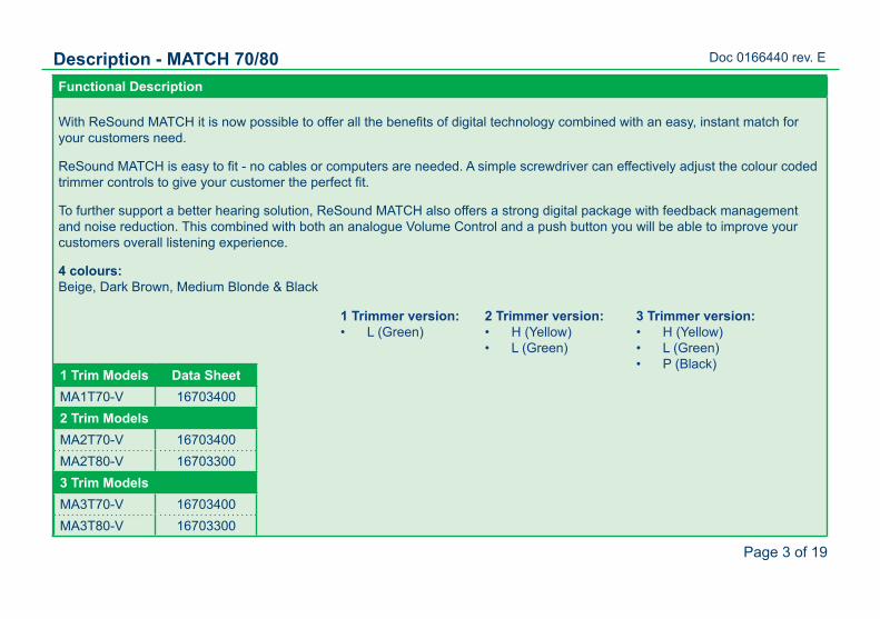
Description - MATCH 70/80Functional Description
With ReSound MATCH it is now possible to offer all the benefits of digital technology combined with an easy, instant match for your customers need.
ReSound MATCH is easy to fit - no cables or computers are needed. A simple screwdriver can effectively adjust the colour coded trimmer controls to give your customer the perfect fit.
To further support a better hearing solution, ReSound MATCH also offers a strong digital package with feedback management and noise reduction. This combined with both an analogue Volume Control and a push button you will be able to improve your customers overall listening experience.
4 colours: Beige, Dark Brown, Medium Blonde & Black
1 Trim Models Data SheetMA1T70-V 167034002 Trim ModelsMA2T70-V 16703400MA2T80-V 167033003 Trim ModelsMA3T70-V 16703400MA3T80-V 16703300
3 Trimmer version:H (Yellow)• L (Green)• P (Black)•
2 Trimmer version:H (Yellow)• L (Green)•
1 Trimmer version:L (Green)•
Doc 0166440 rev. E
Page 4 of 19
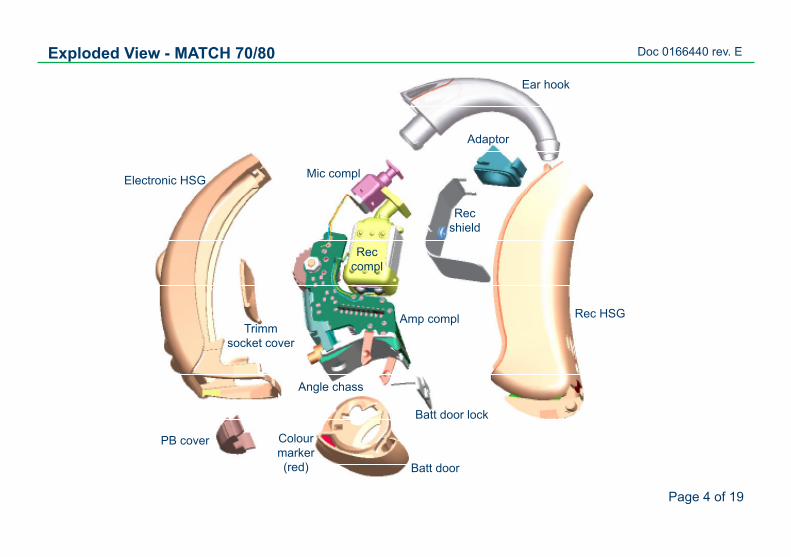
Mic compl
PB cover
Amp compl Rec HSG
Electronic HSG
Trimm socket cover
Angle chass
Batt door
Batt door lock
Exploded View - MATCH 70/80
Ear hook
Rec compl
Colour marker (red)
Adaptor
Rec shield

Doc 0166440 rev. E
Page 5 of 19
Part List - MATCH 70/80
Item Part NoADAPTOR (for the ear hook) 15894000ANGLE CHASSIS (without +/- springs) 16668000PB 95 15327000BATTERY LOCK 15893900BATTERY SPRING +/- 15894300EAR HOOK / TONE TUBE 15894100BABY TONE TUBE 16012900MIC SUSPENSION 15894600MIC EM4446 CX 612-007-015-01MIC COMPLETE 15937200CONFORMAL COATING, SL 1367 **WIRE,ESW,GREEN,7X32U,11MM 15129811WIRE RED INSUL 11MM 7STRANDS 620-011-003-01WIRE YEL INSUL 11MM 7STRANDS 620-011-003-02RUBBER GLUE C-296336310 1901-061
Item Part No.COLOUR MARKER, RED 16011100COLOUR MARKER, BLUE 16011101TEST FIXTURE 16936600CS44 PROG. SOCKET/UNIT 16687500CS44 PROG. CABLE (L), blue 9022 907 69029CS44 PROG. CABLE (R), red 9022 907 69019VC 50K LINEAR ±10% PJ77, BEIGE 15751100VC 50K LINEAR ±10% PJ77, BROWN * 15751101AMP COMPL,MA1T,BEIGE 16381100AMP COMPL,MA1T,BROWN * 16381101AMP COMPL,MA2T,BEIGE 16497500AMP COMPL,MA2T,BROWN * 16497501AMP. COMPL. 3TRIMMERS,BEIGE 16485500AMP. COMPL. 3TRIMMERS,BROWN * 16485501
* used for BROWN, MDM BLONDE & BLACK HI
** Conformal coating SL1367 peters coat to be purchased locally. Check e.g. the vendor website http://www.peters.de
Doc 0166440 rev. E
Page 6 of 19
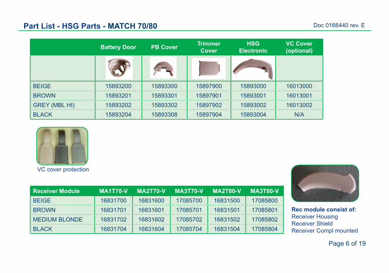
Battery Door PB Cover Trimmer Cover
HSG Electronic
VC Cover (optional)
BEIGE 15893200 15893300 15897900 15893000 16013000BROWN 15893201 15893301 15897901 15893001 16013001GREY (MBL HI) 15893202 15893302 15897902 15893002 16013002BLACK 15893204 15893308 15897904 15893004 N/A
Part List - HSG Parts - MATCH 70/80
Receiver Module MA1T70-V MA2T70-V MA3T70-V MA2T80-V MA3T80-VBEIGE 16831700 16831600 17085700 16831500 17085800BROWN 16831701 16831601 17085701 16831501 17085801MEDIUM BLONDE 16831702 16831602 17085702 16831502 17085802BLACK 16831704 16831604 17085704 16831504 17085804
Rec module consist of:Receiver HousingReceiver ShieldReceiver Compl mounted
VC cover protection
Doc 0166440 rev. E
Page 7 of 19
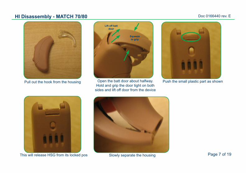
HI Disassembly - MATCH 70/80
Pull out the hook from the housing Open the batt door about halfway. Hold and grip the door tight on both
sides and lift off door from the device
Push the small plastic part as shown
Squeeze to grip
Lift off batt door
This will release HSG from its locked pos Slowly separate the housing
Doc 0166440 rev. E
Page 8 of 19
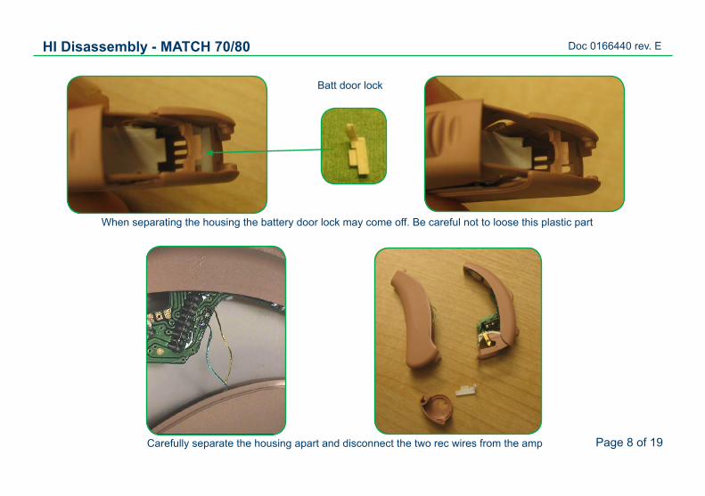
HI Disassembly - MATCH 70/80
Batt door lock
When separating the housing the battery door lock may come off. Be careful not to loose this plastic part
Carefully separate the housing apart and disconnect the two rec wires from the amp
Doc 0166440 rev. E
Page 9 of 19
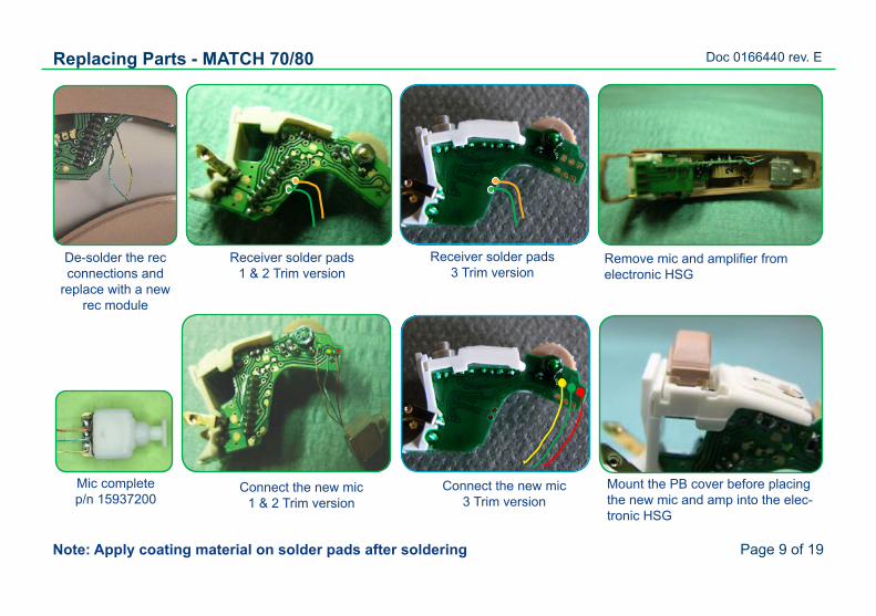
Replacing Parts - MATCH 70/80
Note: Apply coating material on solder pads after soldering
Mic complete p/n 15937200
Remove mic and amplifier from electronic HSG
Connect the new mic1 & 2 Trim version
Mount the PB cover before placing the new mic and amp into the elec-tronic HSG
De-solder the rec connections and
replace with a new rec module
Receiver solder pads1 & 2 Trim version
Receiver solder pads3 Trim version
Connect the new mic3 Trim version
Doc 0166440 rev. E
Page 10 of 19
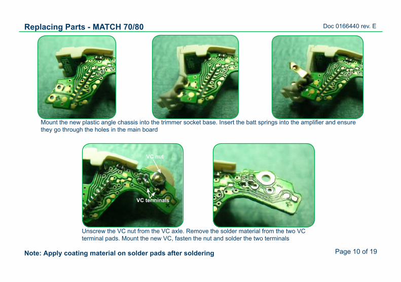
Replacing Parts - MATCH 70/80
Note: Apply coating material on solder pads after soldering
Mount the new plastic angle chassis into the trimmer socket base. Insert the batt springs into the amplifier and ensure they go through the holes in the main board
Unscrew the VC nut from the VC axle. Remove the solder material from the two VC terminal pads. Mount the new VC, fasten the nut and solder the two terminals
VC nut
VC terminals
Doc 0166440 rev. E
Page 11 of 19
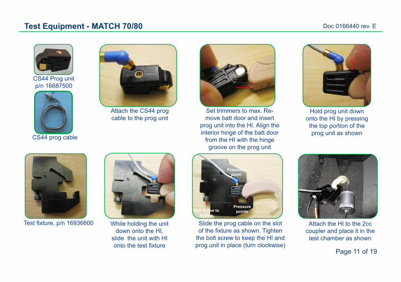
Test Equipment - MATCH 70/80
CS44 Prog unit p/n 16687500
CS44 prog cable
Test fixture, p/n 16936600
Attach the CS44 prog cable to the prog unit
Set trimmers to max. Re-move batt door and insert
prog unit into the HI. Align the interior hinge of the batt door
from the HI with the hinge groove on the prog unit
Hold prog unit down onto the HI by pressing the top portion of the prog unit as shown
While holding the unit down onto the HI,
slide the unit with HI onto the test fixture
Slide the prog cable on the slot of the fixture as shown. Tighten
the bolt screw to keep the HI and prog unit in place (turn clockwise)
Attach the HI to the 2cc coupler and place it in the
test chamber as shown
Pressure points
Pressure point
Bolt screw to tighten
Doc 0166440 rev. E
Page 12 of 19
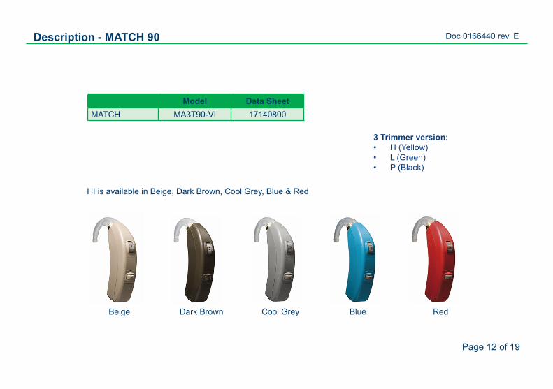
Model Data SheetMATCH MA3T90-VI 17140800
Beige Dark Brown Blue RedCool Grey
HI is available in Beige, Dark Brown, Cool Grey, Blue & Red
Description - MATCH 90
3 Trimmer version:H (Yellow)• L (Green)• P (Black)•
Doc 0166440 rev. E
Page 13 of 19
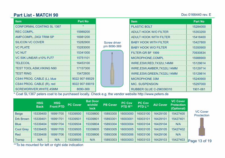
Item Part NoPLASTIC BOLT 15284000
ADULT HOOK W/O FILTER 15353200
ADULT HOOK WITH FILTER 15418400
BABY HOOK WITH FILTER 15427800
BABY HOOK W/O FILTER 15350900
FILTER-GR BF 1999 70930834
MICROPHONE,COMPL 15988900
WIRE,ESW,RED,7X32U,14MM 15129614
WIRE,ESW,AMBER,7X32U,14MM 15129714
WIRE,ESW,GREEN,7X32U,14MM 15129814
MICROPHONE 33M 15240900
MIC. SUSPENSION 15297000
RUBBER GLUE C-296336310 1901-061
Item Part NoCONFORMAL COATING SL 1367 *
REC COMPL. 15989200
AMP.COMPL.,DIGI TRIM SP 16981200
SILICON VC COVER 15282900
VC PLATE 15283000
VC NUT 15341000
VC 50K LINEAR ±10% PJ77 15751101
TELECOIL 16453100
TEST TOOL ASM,VIKING N90 17157300
TEST RING 15472600
CS44 PROG. CABLE (L), blue 9022 907 69029
CS44 PROG. CABLE (R), red 9022 907 69019
SCREWDRIVER,WHITE,45MM 8090-369
Part List - MATCH 90
HSG Back
HSG Front PTD PC Cover
Bat Door w/child
lockPB Cover PC Cov
PTD R**PC Cov PTD L** AU Cover
VC Cover Protection (Optional)
Beige 15339400 16991700 15339500 15339800 15893300 16003000 16003100 16429100 15427400
Drk Brown 15339401 16991701 15339501 15339801 15893301 16003001 16003101 16429101 15427401
Blue 15339404 16991704 15339504 15339804 15893304 16003004 16003104 16429104 N/A
Cool Grey 15339405 16991705 15339505 15339805 15893305 16003005 16003105 16429105 15427402
Red 15339406 16991706 15339506 15339806 15893306 16003006 16003106 16429106 N/A
Transp N/A N/A 15339503 N/A 15893303 16003003 16003103 16429103 15427403
**To be mounted for left or right side indication
VC Cover Proctection
Screw driver p/n 8090-369
* Coat SL1367 peters coat to be purchased locally. Check e.g. the vendor website http://www.peters.de
Doc 0166440 rev. E
Page 14 of 19
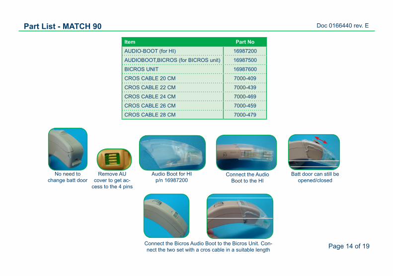
Part List - MATCH 90
Item Part NoAUDIO-BOOT (for HI) 16987200
AUDIOBOOT,BICROS (for BICROS unit) 16987500
BICROS UNIT 16987600
CROS CABLE 20 CM 7000-409
CROS CABLE 22 CM 7000-439
CROS CABLE 24 CM 7000-469
CROS CABLE 26 CM 7000-459
CROS CABLE 28 CM 7000-479
No need to change batt door
Remove AU cover to get ac-
cess to the 4 pins
Audio Boot for HIp/n 16987200
Connect the Audio Boot to the HI
Batt door can still be opened/closed
Connect the Bicros Audio Boot to the Bicros Unit. Con-nect the two set with a cros cable in a suitable length
Doc 0166440 rev. E
Page 15 of 19
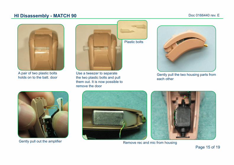
A pair of two plastic boltsholds on to the batt. door
Use a tweezer to separate the two plastic bolts and pull them out. It is now possible to remove the door
Gently pull the two housing parts from each other
Plastic bolts
HI Disassembly - MATCH 90
Gently pull out the amplifier Remove rec and mic from housing
Doc 0166440 rev. E
Page 16 of 19
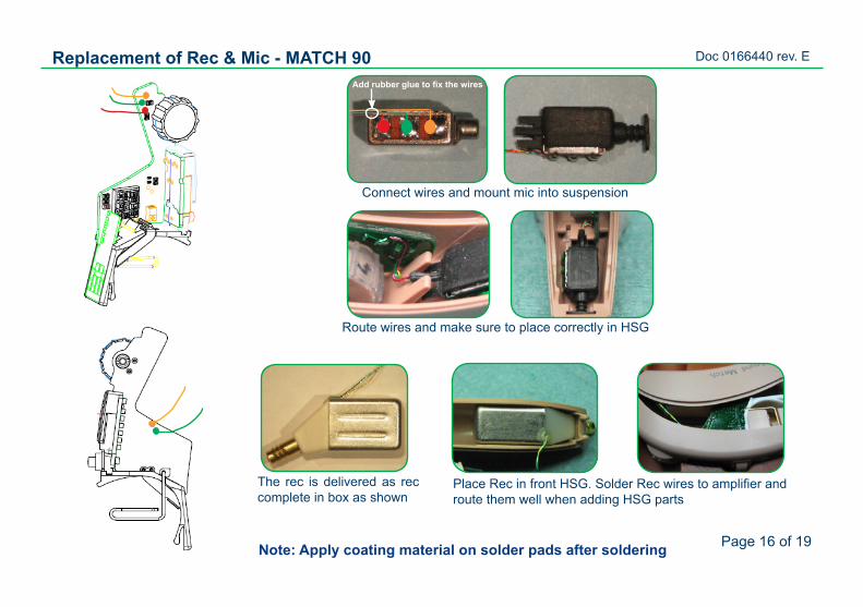
Replacement of Rec & Mic - MATCH 90Add rubber glue to fix the wires
Connect wires and mount mic into suspension
The rec is delivered as rec complete in box as shown
Route wires and make sure to place correctly in HSG
Place Rec in front HSG. Solder Rec wires to amplifier and route them well when adding HSG parts
Note: Apply coating material on solder pads after soldering
Doc 0166440 rev. E
Page 17 of 19
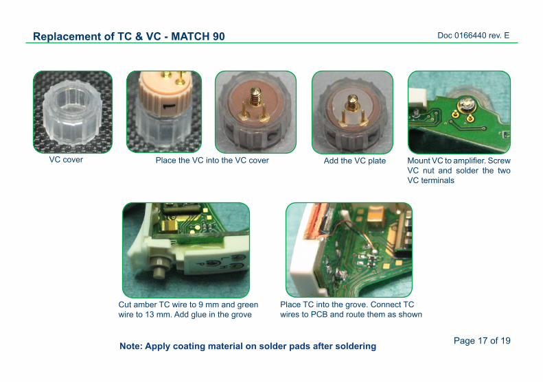
Replacement of TC & VC - MATCH 90
Place the VC into the VC coverVC cover Add the VC plate Mount VC to amplifier. Screw VC nut and solder the two VC terminals
Cut amber TC wire to 9 mm and green wire to 13 mm. Add glue in the grove
Place TC into the grove. Connect TC wires to PCB and route them as shown
Note: Apply coating material on solder pads after soldering
Doc 0166440 rev. E
Page 18 of 19
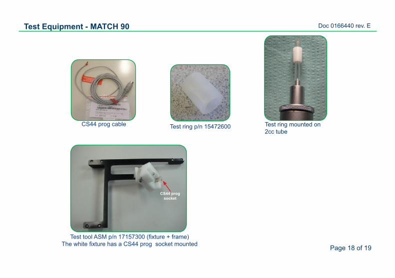
Test Equipment - MATCH 90
Test ring mounted on 2cc tube
CS44 prog cable
Test tool ASM p/n 17157300 (fixture + frame) The white fixture has a CS44 prog socket mounted
CS44 prog socket
Test ring p/n 15472600
Doc 0166440 rev. E
Page 19 of 19
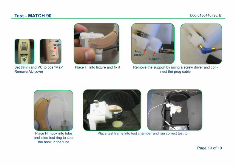
Set trimm and VC to pos “Max”. Remove AU cover
Place test frame into test chamber and run correct test tpi
Test - MATCH 90
Place HI into fixture and fix it Remove the support by using a screw driver and con-nect the prog cable
Progsocket
Place HI hook into tube and slide test ring to seal
the hook in the tube
AU cover
Support