Embed Size (px)
Citation preview

GN ReSound as Global Technical Operations
gto.gnresound.comLautrupbjerg 9 • DK-2750 Ballerup • Denmark
E-Mail: [email protected]
Technical Manual
ReSound Pulse CRT PS60-R&
ReSound Pulse CRT LT PSS60-R
Doc. No. 0127420 rev. B
Page 2 of 15
Table of contentsFeatures ..............................................................................................................................3Part list............................................................................................................................. 4-6Final device .........................................................................................................................7How to separate the HI ........................................................................................................8Microphone assembly..........................................................................................................9Hybrid connections ............................................................................................................10Coating instructions ...........................................................................................................11Colour markers replacement .............................................................................................12Test equipment ............................................................................................................ 13-14Charger spares ..................................................................................................................15
Doc. No. 0127420 rev. B
Page 3 of 15
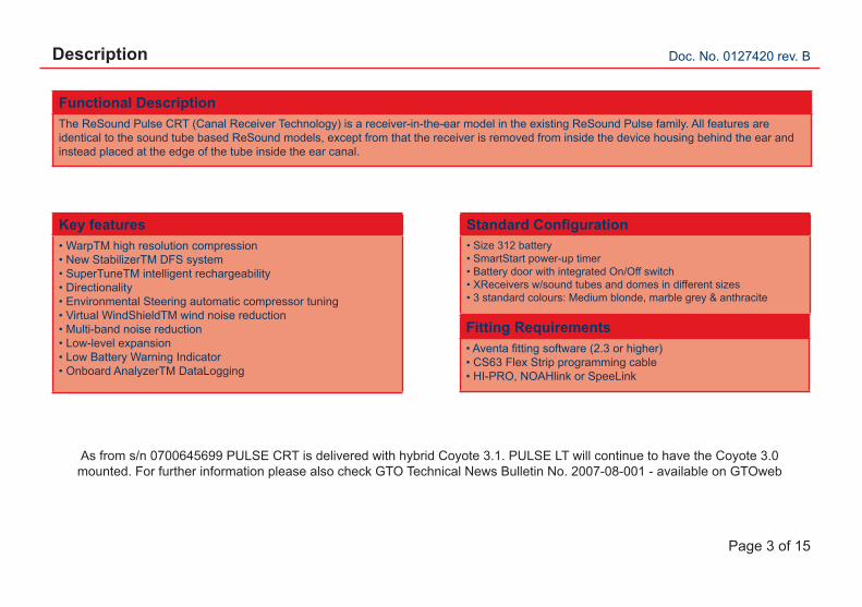
Description
Key features• WarpTM high resolution compression• New StabilizerTM DFS system• SuperTuneTM intelligent rechargeability• Directionality• Environmental Steering automatic compressor tuning• Virtual WindShieldTM wind noise reduction• Multi-band noise reduction• Low-level expansion• Low Battery Warning Indicator• Onboard AnalyzerTM DataLogging
Fitting Requirements• Aventa fitting software (2.3 or higher)• CS63 Flex Strip programming cable• HI-PRO, NOAHlink or SpeeLink
Standard Configuration• Size 312 battery• SmartStart power-up timer• Battery door with integrated On/Off switch• XReceivers w/sound tubes and domes in different sizes• 3 standard colours: Medium blonde, marble grey & anthracite
Functional DescriptionThe ReSound Pulse CRT (Canal Receiver Technology) is a receiver-in-the-ear model in the existing ReSound Pulse family. All features are identical to the sound tube based ReSound models, except from that the receiver is removed from inside the device housing behind the ear and instead placed at the edge of the tube inside the ear canal.
As from s/n 0700645699 PULSE CRT is delivered with hybrid Coyote 3.1. PULSE LT will continue to have the Coyote 3.0 mounted. For further information please also check GTO Technical News Bulletin No. 2007-08-001 - available on GTOweb
Doc. No. 0127420 rev. B
Page 4 of 15
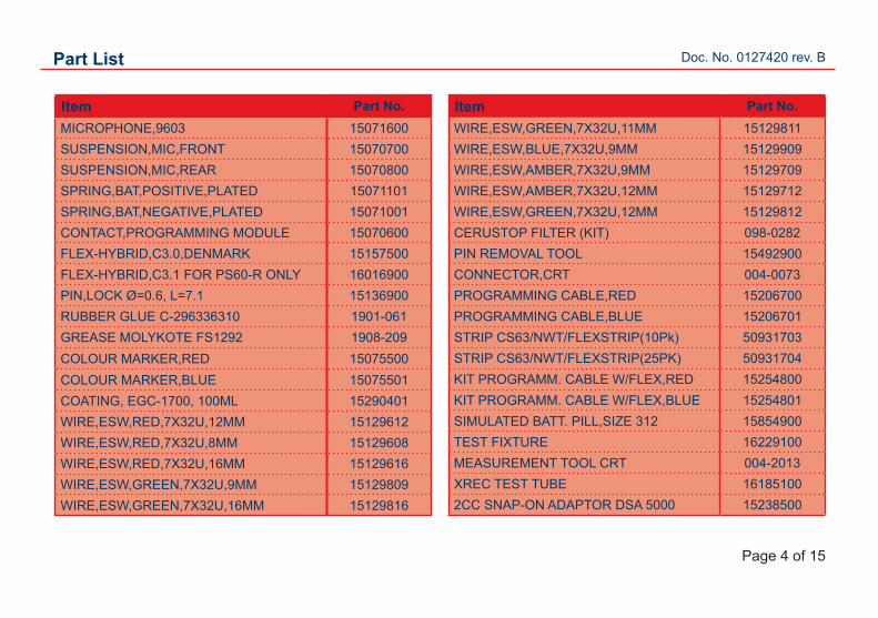
Part List
Item Part No.MICROPHONE,9603 15071600SUSPENSION,MIC,FRONT 15070700SUSPENSION,MIC,REAR 15070800SPRING,BAT,POSITIVE,PLATED 15071101SPRING,BAT,NEGATIVE,PLATED 15071001CONTACT,PROGRAMMING MODULE 15070600FLEX-HYBRID,C3.0,DENMARK 15157500FLEX-HYBRID,C3.1 FOR PS60-R ONLY 16016900PIN,LOCK Ø=0.6, L=7.1 15136900RUBBER GLUE C-296336310 1901-061GREASE MOLYKOTE FS1292 1908-209COLOUR MARKER,RED 15075500COLOUR MARKER,BLUE 15075501COATING, EGC-1700, 100ML 15290401WIRE,ESW,RED,7X32U,12MM 15129612WIRE,ESW,RED,7X32U,8MM 15129608WIRE,ESW,RED,7X32U,16MM 15129616WIRE,ESW,GREEN,7X32U,9MM 15129809WIRE,ESW,GREEN,7X32U,16MM 15129816
Item Part No.WIRE,ESW,GREEN,7X32U,11MM 15129811WIRE,ESW,BLUE,7X32U,9MM 15129909WIRE,ESW,AMBER,7X32U,9MM 15129709WIRE,ESW,AMBER,7X32U,12MM 15129712WIRE,ESW,GREEN,7X32U,12MM 15129812CERUSTOP FILTER (KIT) 098-0282PIN REMOVAL TOOL 15492900CONNECTOR,CRT 004-0073PROGRAMMING CABLE,RED 15206700PROGRAMMING CABLE,BLUE 15206701STRIP CS63/NWT/FLEXSTRIP(10Pk) 50931703STRIP CS63/NWT/FLEXSTRIP(25PK) 50931704KIT PROGRAMM. CABLE W/FLEX,RED 15254800KIT PROGRAMM. CABLE W/FLEX,BLUE 15254801SIMULATED BATT. PILL,SIZE 312 15854900TEST FIXTURE 16229100MEASUREMENT TOOL CRT 004-2013XREC TEST TUBE 161851002CC SNAP-ON ADAPTOR DSA 5000 15238500
Doc. No. 0127420 rev. B
Page 5 of 15
Part list
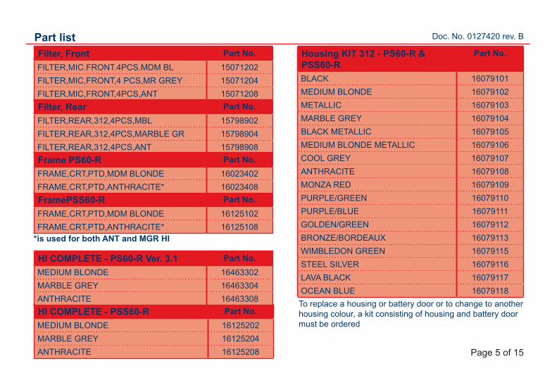
FramePSS60-R Part No.FRAME,CRT,PTD,MDM BLONDE 16125102FRAME,CRT,PTD,ANTHRACITE* 16125108
Filter, Front Part No.FILTER,MIC.FRONT.4PCS.MDM BL 15071202FILTER,MIC,FRONT,4 PCS,MR GREY 15071204FILTER,MIC,FRONT,4PCS,ANT 15071208Filter, Rear Part No.FILTER,REAR,312,4PCS,MBL 15798902FILTER,REAR,312,4PCS,MARBLE GR 15798904FILTER,REAR,312,4PCS,ANT 15798908Frame PS60-R Part No.FRAME,CRT,PTD,MDM BLONDE 16023402FRAME,CRT,PTD,ANTHRACITE* 16023408
HI COMPLETE - PSS60-R Part No.MEDIUM BLONDE 16125202MARBLE GREY 16125204ANTHRACITE 16125208
HI COMPLETE - PS60-R Ver. 3.1 Part No.MEDIUM BLONDE 16463302MARBLE GREY 16463304ANTHRACITE 16463308
*is used for both ANT and MGR HI
Housing KIT 312 - PS60-R & PSS60-R
Part No.
BLACK 16079101MEDIUM BLONDE 16079102METALLIC 16079103MARBLE GREY 16079104BLACK METALLIC 16079105MEDIUM BLONDE METALLIC 16079106COOL GREY 16079107ANTHRACITE 16079108MONZA RED 16079109PURPLE/GREEN 16079110PURPLE/BLUE 16079111GOLDEN/GREEN 16079112BRONZE/BORDEAUX 16079113WIMBLEDON GREEN 16079115STEEL SILVER 16079116LAVA BLACK 16079117OCEAN BLUE 16079118To replace a housing or battery door or to change to another housing colour, a kit consisting of housing and battery door must be ordered
Doc. No. 0127420 rev. B
Page 6 of 15
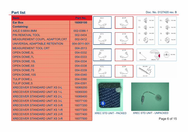
Part listItem Part No.Ear Box 16069100Containing:AXLE 0.68X4.8MM 002-0386-1PIN REMOVAL TOOL 002-0404MEASUREMENT COUPL. ADAPTOR,CRT 002-0412UNIVERSAL ADAPTABLE RETENTION 004-0011-001MEASUREMENT TOOL CRT 004-2013OPEN DOME,5L 054-0332OPEN DOME,7L 054-0333OPEN DOME,10L 054-0334OPEN DOME,5S 054-0338OPEN DOME,7S 054-0339OPEN DOME,10S 054-0340TULIP DOME,L 054-0390TULIP DOME,S 054-0391XRECEIVER STANDARD UNIT XS 0-L 16069200XRECEIVER STANDARD UNIT XS 1-L 16069300XRECEIVER STANDARD UNIT XS 2-L 16069400XRECEIVER STANDARD UNIT XS 3-L 16077100XRECEIVER STANDARD UNIT XS 0-R 16077200XRECEIVER STANDARD UNIT XS 1-R 16077300XRECEIVER STANDARD UNIT XS 2-R 16077400XRECEIVER STANDARD UNIT XS 3-R 16077500
XREC STD UNIT - PACKED XREC STD UNIT - UNPACKED
Doc. No. 0127420 rev. B
Page 7 of 15
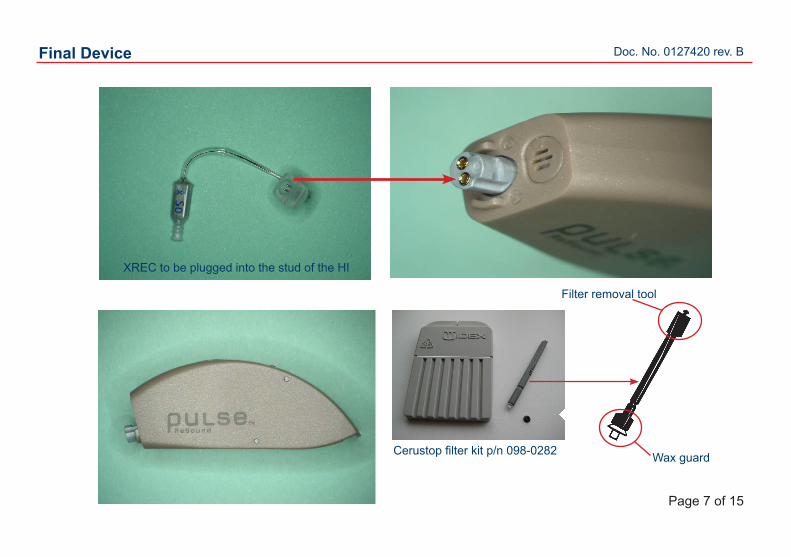
Final Device
XREC to be plugged into the stud of the HI
Cerustop filter kit p/n 098-0282
Filter removal tool
Wax guard
Doc. No. 0127420 rev. B
Page 8 of 15
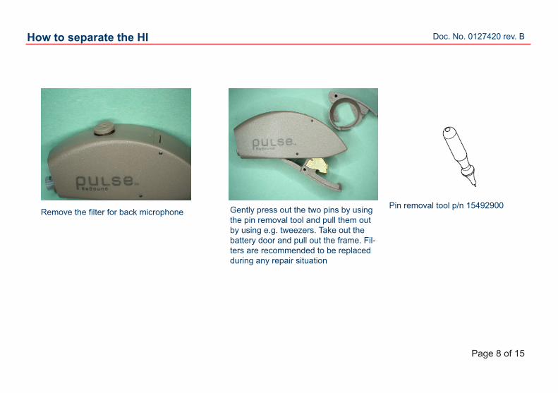
How to separate the HI
Remove the filter for back microphone Gently press out the two pins by using the pin removal tool and pull them out by using e.g. tweezers. Take out the battery door and pull out the frame. Fil-ters are recommended to be replaced during any repair situation
Pin removal tool p/n 15492900
Doc. No. 0127420 rev. B
Page 9 of 15
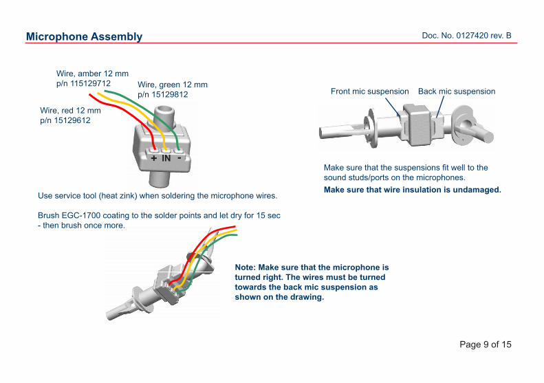
Microphone Assembly
Note: Make sure that the microphone is turned right. The wires must be turned towards the back mic suspension as shown on the drawing.
Use service tool (heat zink) when soldering the microphone wires.
Brush EGC-1700 coating to the solder points and let dry for 15 sec - then brush once more.
Wire, red 12 mmp/n 15129612
Wire, green 12 mmp/n 15129812
Wire, amber 12 mmp/n 115129712
Make sure that the suspensions fit well to the sound studs/ports on the microphones.
Front mic suspension Back mic suspension
-IN+
Make sure that wire insulation is undamaged.
Doc. No. 0127420 rev. B
Page 10 of 15
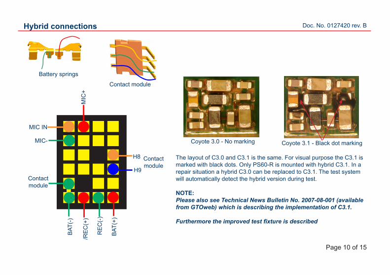
Hybrid connections
Contact module
Battery springs
BAT
(+)
H8
H9
/RE
C(+
)
RE
C(-
)
MIC
+
MIC-
MIC IN
Contact module
BAT
(-)
Contact module
Coyote 3.0 - No marking Coyote 3.1 - Black dot marking
The layout of C3.0 and C3.1 is the same. For visual purpose the C3.1 is marked with black dots. Only PS60-R is mounted with hybrid C3.1. In a repair situation a hybrid C3.0 can be replaced to C3.1. The test system will automatically detect the hybrid version during test.
NOTE: Please also see Technical News Bulletin No. 2007-08-001 (available from GTOweb) which is describing the implementation of C3.1.
Furthermore the improved test fixture is described
Doc. No. 0127420 rev. B
Page 11 of 15
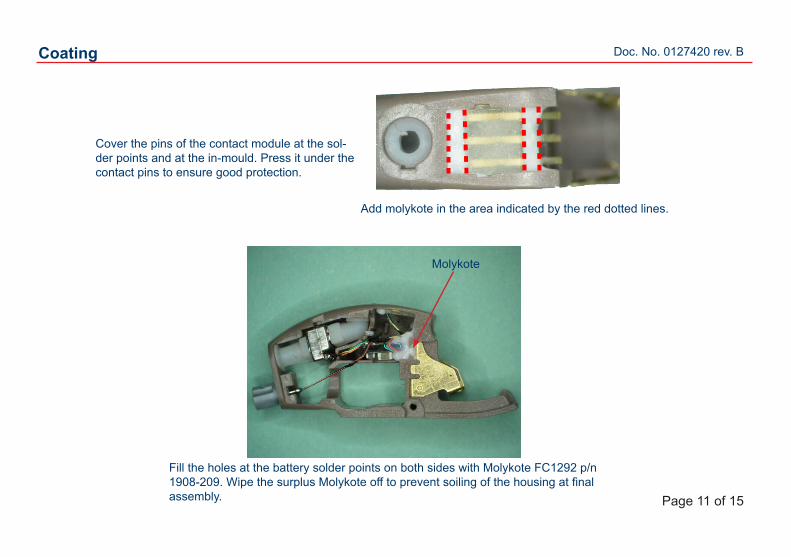
Coating
Cover the pins of the contact module at the sol-der points and at the in-mould. Press it under the contact pins to ensure good protection.
Molykote
Add molykote in the area indicated by the red dotted lines.
Fill the holes at the battery solder points on both sides with Molykote FC1292 p/n 1908-209. Wipe the surplus Molykote off to prevent soiling of the housing at final assembly.
Doc. No. 0127420 rev. B
Page 12 of 15
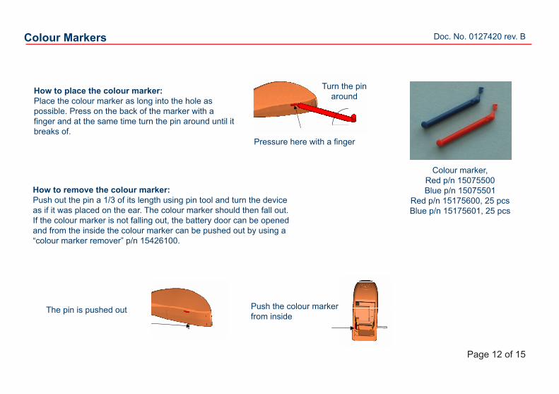
Colour Markers
Turn the pin around
Pressure here with a finger
How to place the colour marker:Place the colour marker as long into the hole as possible. Press on the back of the marker with a finger and at the same time turn the pin around until it breaks of.
How to remove the colour marker:Push out the pin a 1/3 of its length using pin tool and turn the device as if it was placed on the ear. The colour marker should then fall out.If the colour marker is not falling out, the battery door can be opened and from the inside the colour marker can be pushed out by using a “colour marker remover” p/n 15426100.
The pin is pushed out Push the colour marker from inside
Colour marker, Red p/n 15075500Blue p/n 15075501
Red p/n 15175600, 25 pcsBlue p/n 15175601, 25 pcs

Doc. No. 0127420 rev. B
Page 13 of 15
Test equipment
Kit with programming cable, flex strip and clothes-clip:- Red p/n 15254800 - Blue p/n 15254801
Programming cable CS63 blue, Left p/n 15206701.
Programming cable CS63 red, Right p/n 15206700.
Red dot
Blue dotBattery pill must be used:Size 312 p/n 15854900
- Flex strip 3 pin (10 pcs) p/n 50931703 - Flex strip 3 pin (25 pcs) p/n 50931704
Doc. No. 0127420 rev. B
Page 14 of 15
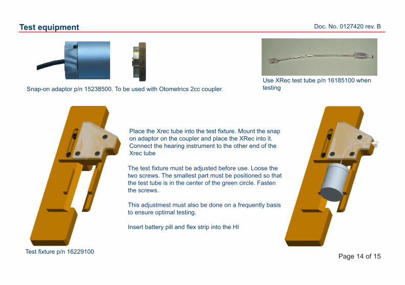
Place the Xrec tube into the test fixture. Mount the snap on adaptor on the coupler and place the XRec into it. Connect the hearing instrument to the other end of the Xrec tube
Test fixture p/n 16229100
Test equipment
Use XRec test tube p/n 16185100 when testing
The test fixture must be adjusted before use. Loose the two screws. The smallest part must be positioned so that the test tube is in the center of the green circle. Fasten the screws.
This adjustmest must also be done on a frequently basis to ensure optimal testing.
Insert battery pill and flex strip into the HI
Snap-on adaptor p/n 15238500. To be used with Otometrics 2cc coupler.
Doc. No. 0127420 rev. B
Page 15 of 15
Charger spares
Spares Part no.Keyring holder 15734700Link for keyring holder 15806700Silicone block 10A 15734300Silicone block 312 15837300Battery slide 10A 15837100Battery slide 312 15837200Power supply EU 15836800Power supply UK 15837900Power supply US 15837500Power supply AUS 15837700
Complete package Part no.RESOUND PULSE SUPERTUNE, EU* 15871100RESOUND PULSE SUPERTUNE, UK* 15870900RESOUND PULSE SUPERTUNE, US* 15871000RESOUND PULSE SUPERTUNE, AUS* 15870100* including all spares