Embed Size (px)
Citation preview
TECHNI CAL MEMCRANDUS
NATIONAL ADVISORY COMiITTEE FOR A.RCNAUTICS
No. 582
EFFECTS OF THE END FIXATION OF AIRPLANE STRUTS
By Alfred Teichnann
Fror Zeitschrift f Fluteohnik unci otorluftschiffahrt ay 28, 1930
ffiOM1!*W
JUt p.'U .up.=m
iS1Wt
LMSY &D 4MPON,
'U ThF ft
-., r'
Washington September, 1030
WASHNGTN 25. D.G.
https://ntrs.nasa.gov/search.jsp?R=19930094834 2018-09-06T10:39:23+00:00Z
NATIONAL ADVISORY COMMITTEE FOR AERONAUTICS.
TEC}flICAL MEMORANDUM NO. 582.
EFFECTS OF THE END FIXATION OF AIRPLANE STRUTS.*
By Alfred Teichmann.
Various inquiries of the D.V.L. indicate that there is
still considerable uncertainty concerning the problem of the
effects of the end fixation of airplane struts as hitherto treat-
ed. In the present communication this problem will be discussed
in as intelligible a rnaner as possible, with reference to the
literature on the subject. This communication is in response
to numerous requests. It contains no new information, and its
method of presentation is not directly related to any of the
works referred to.
Calculation of Struts in Frameworks with Rigid Joints
1. General Remarks on the Effects of Fixation
On the assumption that the deformations are small, the dis-
placements of the joints of a framework can be represented by
a linear system of equations. In certain loading conditions
(buckling conditions), the denominator determinant of this sys-
temo. ' equations disappears. Consequently, indeterminate and
infinitely great joint displacements aepoduced,---i.-e.,- the
system becomes unstable and collapses. ________________ * u Einspannwirung 'oei Knickstben in Flugzeug-Fachwerken. From Zeitschrift fur Flugtechnik und. Motorluftschiffahrt, May 28, 1930, pp. 249-254.
N.A.CeA. Technical Memorandum No. 582
2
Contrary to the customary method of expression, not simply
one member buckles, but the whole system acquires a buckling
condition under a critical load. This occurs oftenest in frame-
works with rigid joints, only when the stresses in a few members
exceed the load, at which buckling would occur in nonrigid fric-
tionless end supports - u nat11 al tt buckling load (B1eich).*
The possibility that individual members may sometimes buck-
le is offset, however, by the greater clearness. The fact that
the "natural" compression load can be exceeded in the compres-
zion members, is designated, in this method of presentation,.
as the "end-fixation effect." It is fundamentally wrong, in
complex frameworks, to calculate with It end_fixation factors"
which are independent of the structure and stressing of the
whole system. If, for example, the "natural" buckling load
is reached simultaneously in all compression members, no trend
fixation effect" is produced, except in special systems.
For simplicity in the determination of the buckling condi-
tions, it is assumed that the compression members of the frame-
work (before buckling begins) are subjected to only normal
stresses, In reality, however, due to rigid joints, every
member is subjected to bending moments resulting from deforma-
tions of the framework.. The-mem-be-r-s_ar then subjected to ten-
*Afl axially compressed lattice member, for exampiybikie before the natural buckling load is reached in a single member. In the first case, the buckling of the framework is comparable with so-called local buckling.
N.A.C.A. Technical Memorandum No. 582 3
sue or buckling stresses.
Due to the resulting secondary stresses, failure occurs
even below the theoretical buckling load, namely, whn the fail-
ing stress of the critical member is exceeded. It is essential
that these secondary stresses attain their maximum values in
the annealed welded zones of the members, provided the case is
not one of strongly bent compression members where, due to the
added moment of the normal force, the maximum value of the sec-
ondary stresses may reside in the-middle of the member.
Since these detrimental secondary stresses are ordinarly
disregarded by assuming the members to have pin-end supports,
it would be logical to disregard likewise the favorable effect
of the end fixation. In any event, the consideration of the
end-fixation effect must be omitted from the outset in thecase
of those members in which there is a possibility of strong sec-
ondary stresses.
2. Literature on the Calculation of the Buckling of Struts
For immediate practical use, a discussion of the theory of
the buckling of a system of members in one plane is found in
the book by F. Bleich (Reference 1, page 24). Along with the
general theory, this book cont rous--s-i-mpl-eapproxmat ion
formulas. These problems are discussed separately by Bleich
(References 2 and 3).
Another presentation- of the theory of the buckling of a
N.A.C.A. Technical Memorandum No. 582 4
planar system of members from its plane is contained in Zimmer-
mann's book (Reference 4). Zinimermann's presentation is charac-
terized by the introduction of the obvious conception of the
fixation coeffic±ent
m = bending moment &t end of member _________-corresponding rotation of end cross section'
that is, a measure for the end-fixation effect which a loaded
or nonloaded strut can produce, or which it requires to prevent
buckling. The book is a summary of Zimmermann's earlier works,
which appeared in the reports of the Prussian Academy of Sci-
ences (Preussische Akademie der Wissenschaften) in the years
1905 to 1925).
The stability of planar frameworks (including those with
hinged joints) is treated in a general way in the iorks of Von
Mses (Reference 5); Von Mjses and Ratzersdorfer (References
6 and 7). The stability of space frameworks with any kind of
joints is treated in the report of F. Bleich and H. Bleich (Ref-
erence 8). A future report by the same writers is announed
Other referencs are given in the above-mentioned works.
------ 3.Estimation of the End-Fixation Effect
The accurate determination of the buckling load and of the
buckling-bending stresses would require tedious calculations.
N.A.C.AS Technical Memorandum No. 582
5
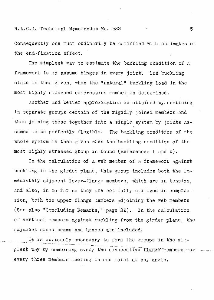
Consequently one must ordinarily be stified With estimates of
the end-fixation effect.
The simplest way to estimate the buckling condition of a
framework is to assume hinges in every joint. The buckling
state is then given, when the natural" buckling load in the
most highly stressed compression member is determined.
Another and better approximation is obtained by combining
in separate groups certain of the rigidly joined members and
then joining these together into a single system by joints as-
sumed to be perfectly flexible. The buckling condition of the
whole system is then given when the buckling condition of the
most highly stressed group is found (References 1 and 2).
In the calculation of a web member of a framework against
buckling in the girder plane, this group includes both the im-
mediately adjacent lower-flange members, which are in tension,
and also, in so far as they are not fully utilized in compres-
sion, both the upper-flange members adjoining the web members
(See also "Concluding Remarks," page 22). In the calculation
of vertical members against buckling from the girder plane, the
adjacent cross beams and traces are included.
It is obviously necessary to form the groups in te sim-
plest way by combining every two consecutiv fI genembers;--or--
every three members meeting in one joint at any angle.
N.A.C.A. Technical Memorandum N0. 582 6
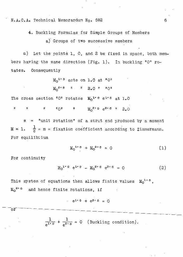
4. Buckling Formulas for Simple Groups of Members
aY Groups of tw successive members
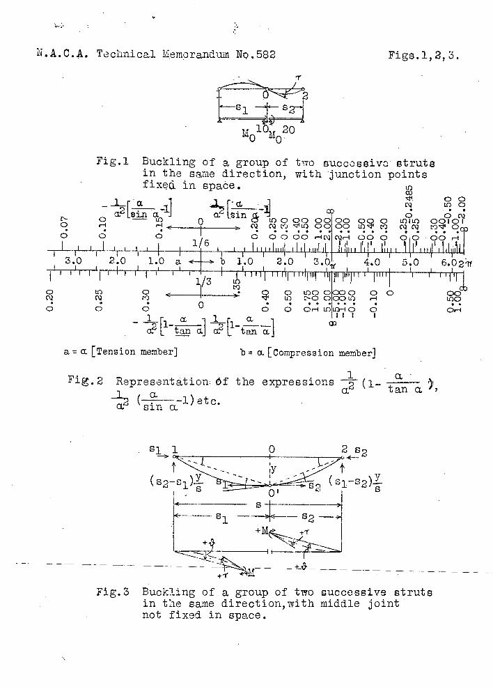
a.) Let the point 1, 0,
bers having the same direction
tates. Consequently
M0 1 ° acts on
1ir 2 • O It it
0
The cross section "0" rotates
and 2 be fixed in space, both rnem-
(Fig. 1). In buckling "0" ro-
1.0 at "0"
2.0 Ii "0"
M0 ° e'° at 1.0
It II II 11011 It MO2 e2 It 2.0
e = "unit rotation" of a strut end produced by a moment
M 1. - = m = fixation coefficient according to Zimmermann.
For equilibium
+ MO2 ° = 0 Ci)
For continuity
M0° e 1 ° - MO2 ° e2 ° = 0 (2)
This system of equations then allows finite values M01°,
M0 ° and hence finite rotations, if
e° + e2 ° = 0
1 1 e'° + ----- = 0 (Buckling condition).
NA.C.A. Technical Memorandum No. 582
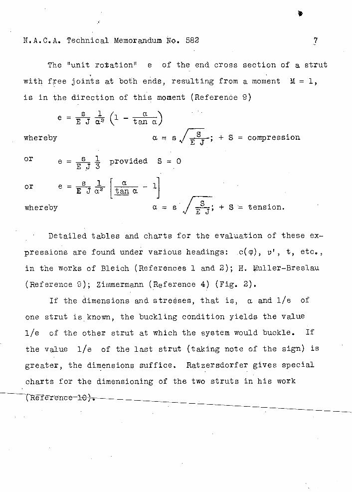
The unit rotation t' e of the end cross section of a strut
with free joints at both erds, resulting from a moment M = 1,
is in the direction of this moment (ReferenOe 9)
Si ___ e =(' - ta a)
wher eby a sj; + S = compression
e = provided S = 0
or
a -1 EJa2 tana
whereby a s ; + S tension.
Detailed tables and charts for the evaluation of these ex-
pressions are found under various headings: .c(cp), i,', t, etc.,
in the works of Bleich (References 1 and 2); H. Muller-Breslau
(Reference 9); Zinimermann (Reference 4) (Fig. 2).
If the dimensions arid streses, that is, a and lie of
one strut is known, the buckling condition yields the value
lie of the other strut at which the system would buckle. If
the value lie of the last strut (taking note of the sign) is
greater, the dimensions suffice. Ratzersdorfer gives special
charts for the dimensioning of the two struts in his work
7
N.A.C.A. Technical Memorandum No. 582
8
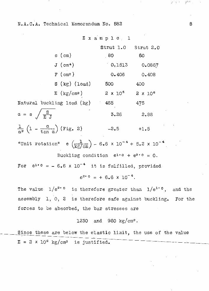
Example . 1
Strut 1.0 Strut 2.0
s (cm) 80 60
J (om4 ) 0,1513 0.0867
F (crn2 ) 0.406 0.408
S (kg) (ioa.) 500 400
E (kg/cm2 ) 2 x 10⁶ 2 x 10⁶
Natural buckling load (kg) 465 475
- a = s 3.26 2.88
(i- ° -) (Fig. 2) --2.5 +1.5
tana
"Unit rotation" e (kcm) - 6.6 x 10 + 5.2
Buckling condition e l O + e2 ° = 0.
For e 1 ° = - 6.6 x i0 it is fulfilled, provided
c 2 '° = + 6.6 x i0.
The value 1/e20 is therefore greater than 1/e'°, and the
assembly 1, 0, 2 is therefore safe against buckling. For the
forces to be absorbed, the bar stresses are
1230 and 980 kg/cm2.
Since these are below the elastic limit, the use of the value
E = 2 X l0
N.A.C.A. Technical Memorandum No. 582
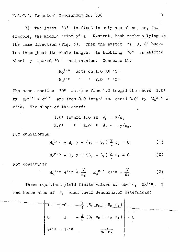
) The joint "O s is fixed in only one plane, as, for
example, the middle joint of a K-strut, both members lying in
the same direction (Fig. 3). Then the system "1, 0, 2" buck-
les throughout its whole length. In buckling 1 Q 1 is shifted
about y toward O" and rotates. Consequently
fl acts on 1,0 at "0"
MO2 It II 2.0 U "0"
The cross section rotates from 1.0 toward the chord 1.0'
by M0 ° X e' 0 and from 2.0 toward the chord 2.0' by M O2 ° X
e 2 C. The slope of the chord:
For equilibrium
1.0' toward 1.0 is i9i =
2.O " 2.0 = - Y/52
M° +.s1 y + (S2 - s) s1 = 0 (1)
For continuity
Mo2 ° - S2 y + (S - S ) S2 0 (2) 2 1 s
y - o___ (3) 0 e 0 + = M2 0 e2
These equations yield finite values o± Mo1 ° , MO2 ° , y
and hence also of T when their denominator determinant
1
0 1 - . (S 1 2 + 2 s 1 ) = 0
- e2 ° -------1 2
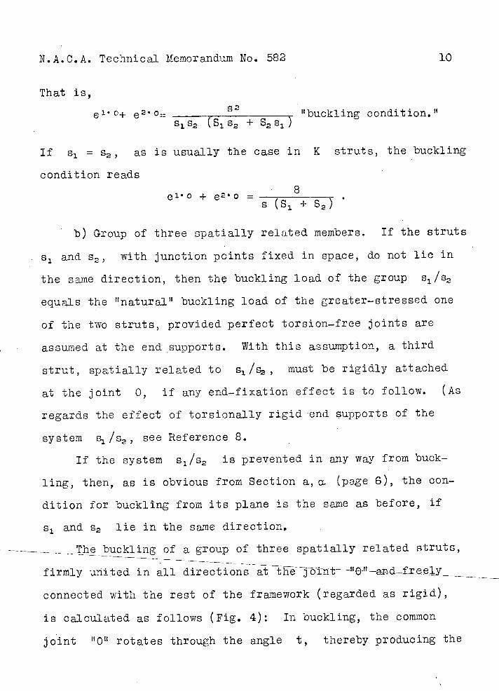
N.A.C.A. Technical Memorandum No. 582 10
That is,
e'°+ e 2 °= buck1ing condjtion. s 1 s2 (S12 + s2sj
If s = as is usually the case in K struts, the buckling
condition reads
8 e 1 O + e 21 O =
s (s 1 ± s2)
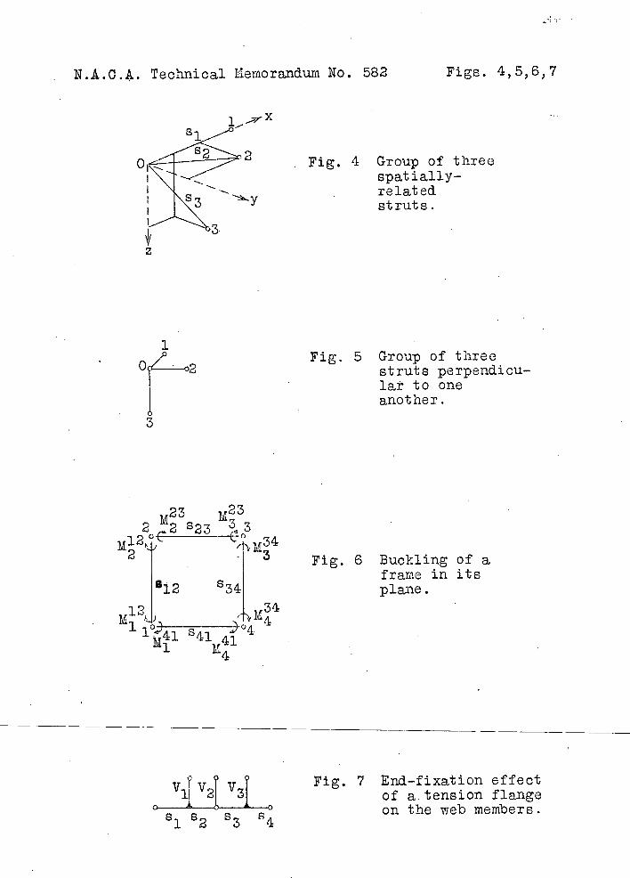
b) Group of three spatially related members. If the struts
s and s2 , with junction points fixed in space, do not lie in
the same direction, then th buckling load of the group s1/s2
equals the It naturaj)t buckling load of the greater-stressed one
of the two struts, provided perfect torsion-free joints are
assumed at the end supports. With this assumption, a third
strut, spatially related to 1/2 , must be rigidly attached
at the joint 0, if any end-fixation effect is to follow. (As
regards the effect of torsionally rigid end supports of the
system s/s, see Reference 8.
If the system s 1 /s2 is prevented in any way from buck-
ling, then, as is obvious from Section a, a. (page 6), the con-
dition for buckling from its plane is the same as before, if
s 1 and 2 lie in the same direction,
Tl buckling of a group of three spatially related struts,
firmly united in all
connected with the rest of the framework (regarded as rigid),
is calculated as follows (Fig. 4): Ifl buckling, the common
joint "0 rotates through the angle t, thereby producing the
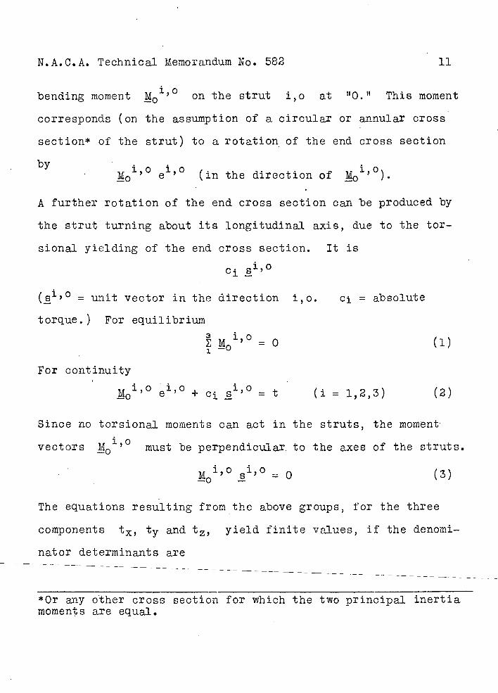
N.A.C.A. Technical Memorandum No. 582 11
bending moment M'° on the strut i,o at "0." This moment
corresponds (on the assumption of a circular or annular cross'
section* of the strut) to a rotation , of the end cross section
bye ' (in the direction of .k )•
A further rotation of the end cross section can be produced by
the strut turning about its longitudinal axis, due to the tor-
sional yielding of the end cross section. It is
ci
(8i,o = unit vector in the direction i,o. Cj = absolute
torque.) For equilibrium
= 0 (i)
For continuity
M1° el0 + cj = t (i = 1,2,3) (2)
Since no torsional moments can act in the struts, the moment
vectors must be perpendicular. to the axes of the struts.
M'0 3io
= 0
(3)
The equations resulting from the above groups, for the three
components t, ty and t, yield finite values, if the denomi-
nator determinants are
*Or any other cross section for which the two principal inertia moments are equal.
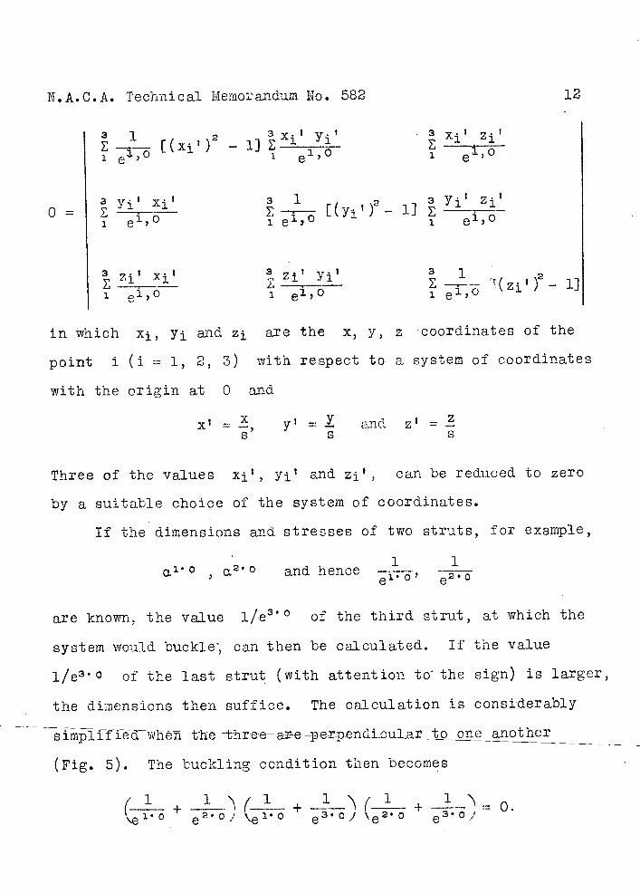
N.A.C.A. Technical Merno'andum No. 582
12
1 Xj,' Yj t Xj Zj [(xj) 2 -
1 e"0 1 ei3O
Yj' XjT 1 2 3 Yj' Zj
e1,6- 1]
1 c''° 1 e'' 0 e''0 1
in which X, yj arid Zj are the x, y, z coordinates of the
point ± (i = 1, 2, 3) with respect to a system of coordinates
with the origin at 0 and
X I =, y' =1 and z' =-
5 S S
Three of the values X' , yj' and Zj t , can be reduced to zero
by a suitable choice of the system of coordinates.
If the dimensions and stresses of two struts, for example,
1 1
a 2 ° and hence ei0' e0
are known, the value l/e 3 ° of the third strut, at which the
system would buckle; can then he calculated. If the value
° of the last strut (with attention to the sign) is larger,
the dimensions then suffice. The calculation is considerably
Bimpi f fedwiefl the- throe—ar-e -perpencd aul a t ore another - - -
(Fig. s). The buckling condition then becomes (1 + 1 .(-J_+_2-_'\( +_—'\=o. \e° e2°e'° e3°/e2° e3°"
NSA.C.A. Technical Memorandum No. 582 13
In this case, bu.k1ing occurs when the buckling conditiOn of the
most highly stressed component S s, s S3 or 2 s3 is ful-
filled for buckling in its plane.
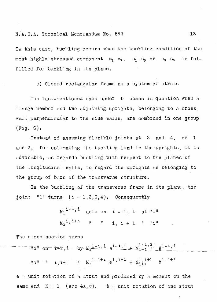
c) Closed rectangular frame as a system of struts
The last-mentioned case u.nder b comes in question when a
flange member and two adjoining uprights, belonging to a cross
wail perpendicular to the side walls, are combined in one group
(Fig. 6).
Instead of assuming flexible joints at 2 and 4, or 1
and 3, for estimating the buckling load in the uprights, it is
advisable, as regards buckling with respect to the planes of
the longitudinal walls, to regard the uprights as belonging to
the group of bars of the traneverse structure.
In the buckling of the transverse frame in its plane, the
joint turns (i = 1,2,3,4). Consequently
acts on i - 1, 1 at
fl" 1, 1 + 1
The cross section turns
- -fl-i-fl- i°i--by--M—e-22i -+- '-:.i-.,i h-- - - -
Ujil fi 1,1+1 Mil,l+1 e1'1] 1+1 .1,1+1
+M1 4. 1 e
e = unit rotation of a strut end produced by a moment on the
same end 1 = 1 (see 4a,a). è = unit rotation of one strut
N.A.C.A. Technical Mernorandnm No. 582 14
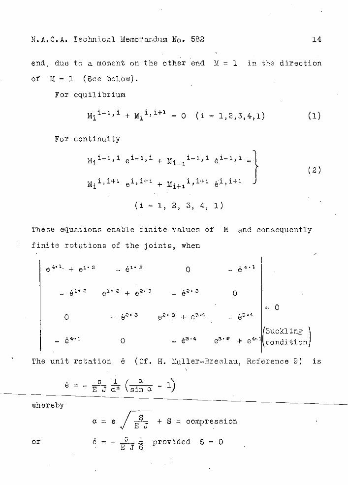
end, due to a moment on the other end M = 1 in the direction
of M = 1 (See below).
For equilibrium
M.i_1,i + Mj" =O (i = 1,2,3,4,1) (i)
For continuity
Mj' 1 ' e''' + M... 1 1 ''' é''' =
1 (2)
e' 1 ' + M1+1 1 ' '4 ' ej-, i+ ' J
(1 = 1, 2, 3, 4, 1)
These equations enable finite values of M and consequently
finite rotations of the joints, when
e 4 ' + e' 2 -. e12 0 -
- 1' 2 e1 2 ± - e 2• 0
1 0 - è2 + e3 -
fEuckling - 0 - e3 + e condition
The unit rotation é (Cf. H. Mu11er-Breiau, Reference 9) is
- __p_ L (_a
- i) E J a 2 \Slfl a ...
whereby
= s + S =. compression
or é = - . provided S = 0 EJ6
N.A.C.A. Technical Memorandum No. 582
15
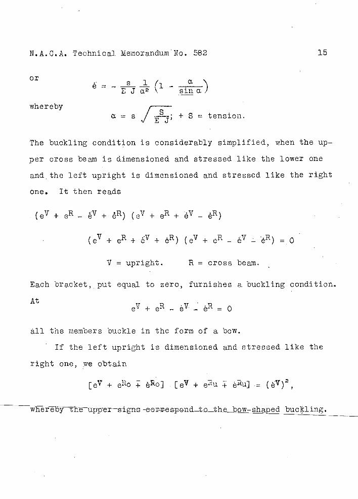
or a E J a2 \ sin a)
whereby r a g J -.%; + S = tension.
The buckling condition is considerably simplified, when the up-
per cross beam is dimensioned and stressed like the lower one
and-, the left upright is dimensioned and stressed like the right
one. It then reads
(eV + eR - èV + ) (eV + eR + éV - éR)
(eV + eR + + eR ) (eV + eR ;.. = 0
V = upright. R = cross beam.
Each bracket, put equal to zero, furnishes a buckling condition.
At - e + e- - - = 0
all the members buckle in the form of a bow.
If the left upright is dimensioned and stressed like the
right one, we obtain
[e + eo - e-o] [eV+ eRu èU]= (éV)2
bucki ing.
S
Js
F
S
E
Natural load
A)
(cm)
(cm14)
(cm2)
(kg) (load)
(kg/cm)
buckling (kg)
(Fig. 2)
N.A..C..A. Technical Memorandum No. 582
16
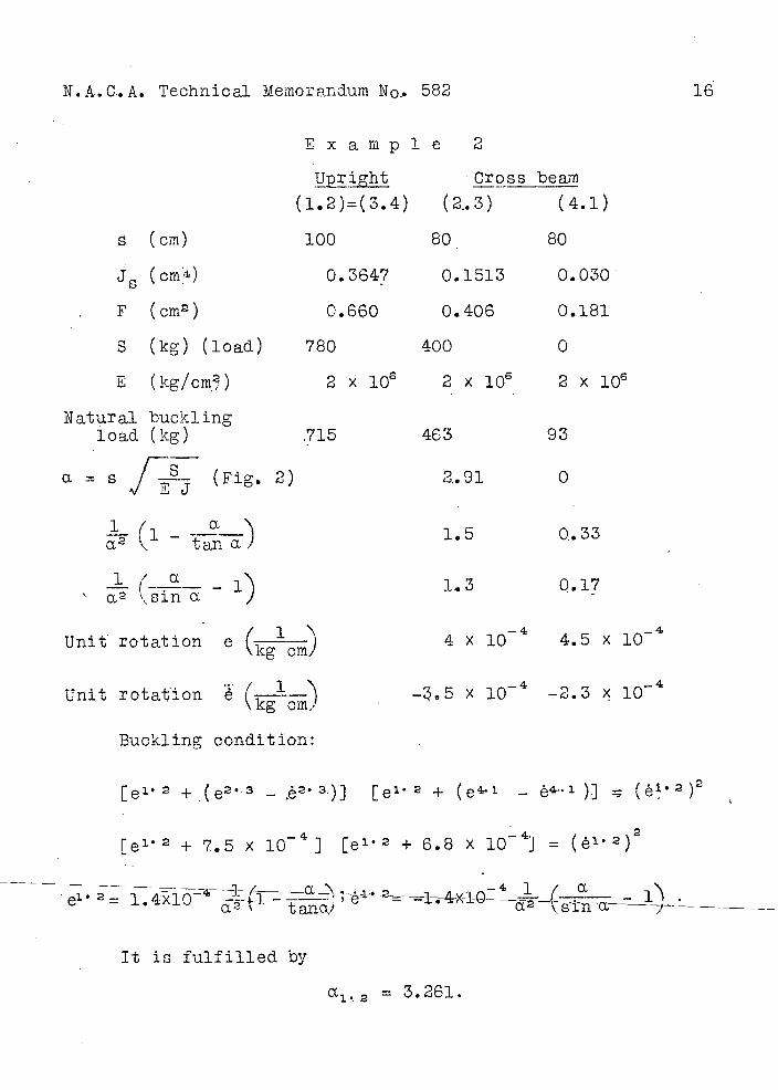
Example 2
Upright Cross beam
(l.2)=(3.4) (2.3) (4.1)
100 80 80
0.3647 0.1513 0.030
0.660 0.406 0.181
780 400 0
2x1OG 2xl0 2x10⁶
715 463 93
2.91 0
1 (ia
a 2 - a
- (--.- - 1 a2 'sinO
Unit rotation e (icglcrn)
Unit rotation é (---)
Buckling condition:
1.5 0.33
1.3 0.17
-4 _4 4 x 10 4.5 x 10
-.5 x 10 -2.3 ç 10
[e1 2 + (e23 - 2• 3)] [e1 2 + ( e' - 4-.1 )] - ( e1 2)2
[e 12 + 7.5 x 1O 4 ] [ e' 2 + 6.8 x i0] = (e1.2)2
& . .2 4xiO na----'-)
It is fulfilled by
= 3.261.
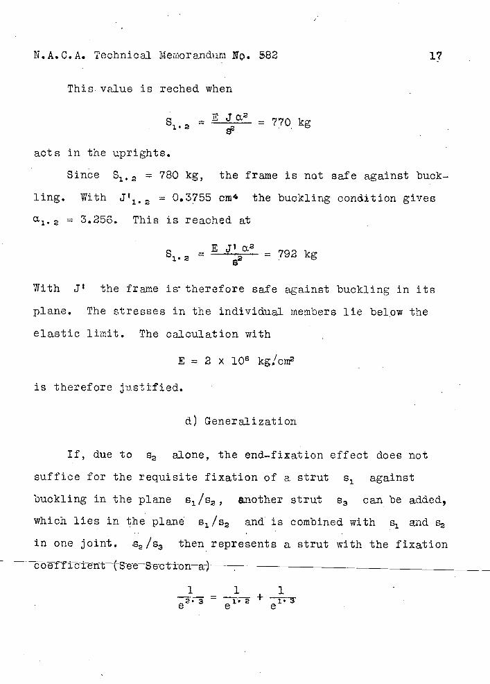
N.AIC.A. Technical Memorandum No. S82 17
This. value is reched when
S LJa2 - 1*2 - 770 kg
acts in the uprights.
Since S1 . 2 = 780 kg, the frame is not safe against buck-
ling. With = 0.3755 cm4 the buckling conthtion gives
= 3.256. This is reached at
E J1 a,2 1 . 2 = 2 =792kg
With J' the frame is' therefore safe against buckling in its
plane. The stresses in the individual members lie below the
elastic liniit. The calculation with
E = 2 x l0 kgicm2
is therefore justified.
a) Generalization
If, due to 2 alone, the end-fixation effect does not
suffice for the requisite fixation of a strut s 1 against
buckling in the plane 1/2, another strut 83 can be added,
which lies in the plane l/2 and is combined with s1 and 2
in one joint. s2 /s3 then represents a strut with the fixation -
bffiieiitSeeSect-i-on—a-)------------------------
1 1 = +
N.A.C.A. Technical Memorandum No. 582
18
As regards the combination of several struts in groups, see the
references.
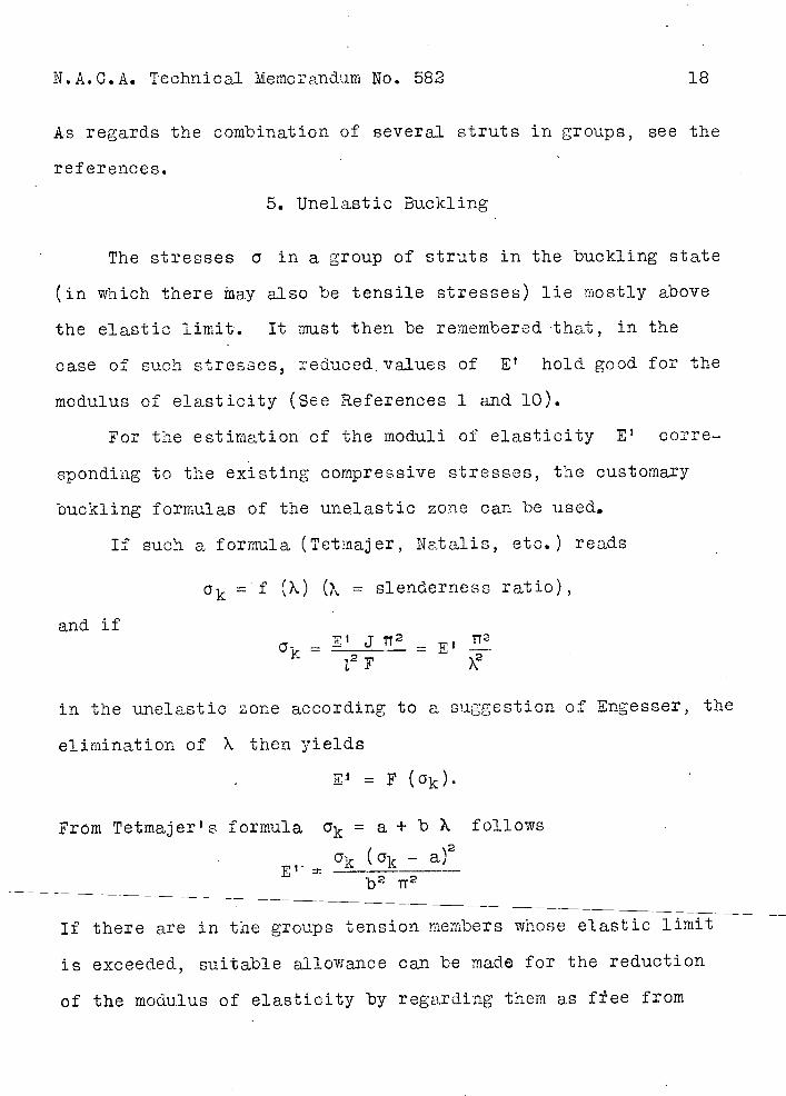
5. Unelastic Buckling
The stresses a in a group of struts in the buckling state
(in which there ay also be tensile stresses) lie mostly above
the elastic limit. It must then be remembered that, in the
case of such stresses, reduced values of E' hold good for the
modulus of elasticity (See References 1 and 10).
For the estimation of the moduli of elasticity E 1 corre-
sponding to the existing compressive stresses, the customary
buckling formulas of the unelastic zone can be used.
If such a formula (Tetmajer, Natalis, etc.) reads
() (? = slenderness ratio),
and ifa- = E' j 2
E
in the imelastic zone according to a suggestion of Engesser, the
elimination of X then yields
= F (ak).
From Tetmajer t s formula 0k = a + b X follows
ak ( ak - a)2
b2 112
If there are in the groups tension members whose elastic limit
is exceeded, suitable allowance can be made for the reduction
of the modulus of elasticity by regarding them as f±ee from
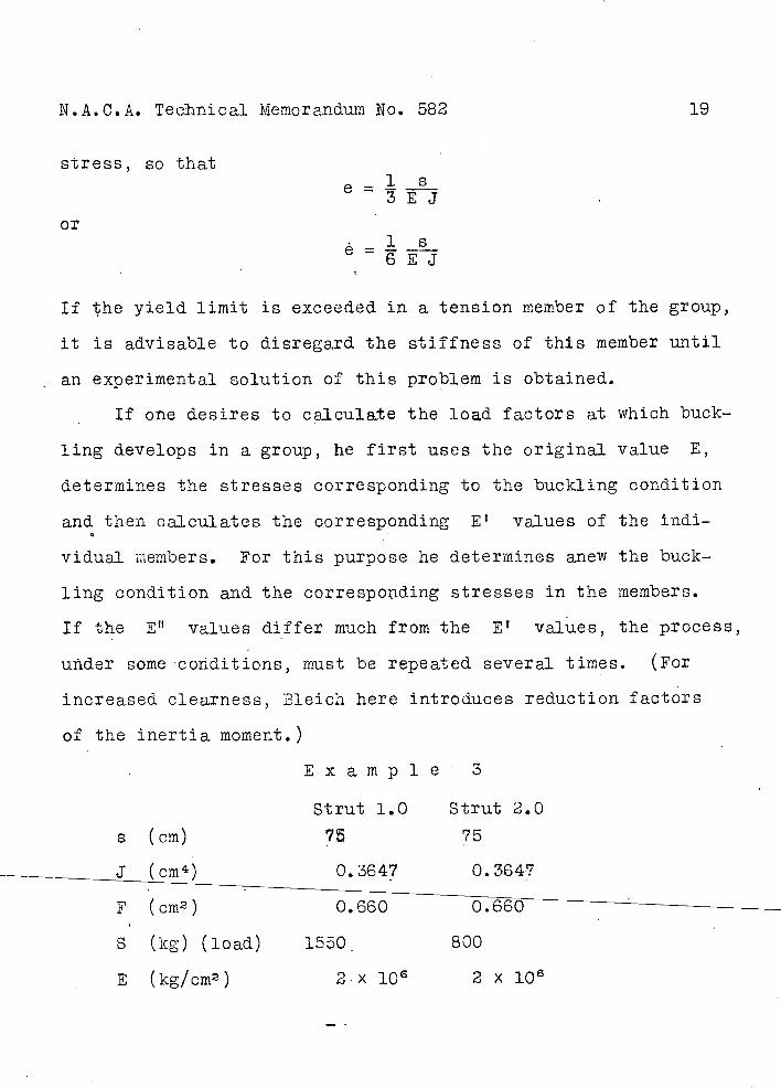
N.A.C.A. Tecinical Memorandum No. 582 19
stress, so that
e--- 3EJ
or.__l S e - EJ
If the yield limit is exceeded in a tension member of the group,
it is advisable to disregard the stiffness of this member until
an experimental solution of this problem is obtained.
If one desires to calculate the load factors at which buck-
ling develops in a group, he first uses the original value E,
determines the stresses corresponding to the buckling condition
and then calculates the corresponding E' values of the indi-
vidual riembers. For this purpose he determines anew the buck-
ling condition and the correspoiding stresses in the members.
If the Elt values differ much from the E' values, the process,
uxider some cotiditions, must be repeated several times. (For
increased, clearness, Bleich here introduces reduction factors
of the inertia moment.)
Example • 3
Strut 1.0 Strut 2.0
s (cm) 75 75
J (cm 4 ) 0,3647 0.364?
F (cm2) 0.660 0.660
S (kg) (load) i550 800
E (kg/cm2 ) 2.x 106 2 x 10⁶
N.A.C.A. Technical Mernoandum No. 582
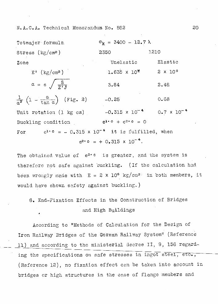
20
Tetrnaj er forrnule, = 3400 - 12.? X
Stress (kg/cm2)
2350 1210
Zone TJne] act ic Elastic
E' (kg/crn2
1.635 x l0 2 x l0
a = S 3.84 2.48.
(1 - ---) (Fig. 2) -0.25 0.68
Unit rotation (1 kg Cm) -0.315 x l0 0.7 x l0
Buckling cond.ition . e1° + e 2 0 = 0
For e'° = - 0.315 x i0 it is fulfilled, when
e2 ° = + 0.315 x l0.
The obtained, value of e 2 0 is greater, and the system is
therefore not safe against buckling. (If the calculation. had
been wrongly made with E = 2 X 10 6 kg/cm2' in both members, it
would. have shown safety against buckling.)
6. End-Fixation Effects in the Construction of Bridges
and High Buildings
According to Methods of Calculation for the Design of
Iron Railway Bridges of the German Railway System tt (Reference
ii) and according to the ministerial decree II, 9, 156 regard-
ing the specifications on safe stresses in ingot steeIët7
(Reference 12), no fixation effect can be taken into account in
bridges or high structures in the case of flange members and
N.A.C.A. Technical Memorandum No. 582
21
the end. diagonals of trapezoidal girders. In general, according
to these specifications, the dimensions of the web members, used
to prevent buckling from the plane of the trusses, are deter-
mined without consideration of any fixation effect.
In dimensioning the web members so as to prevent buckling
in the plane of the truss, allowance can be made for any end-
fixation effect that can be calculated with the distance between
the centersof gravity of the end groups of rivets instead of the
length of the frame. Moreover, in bridge construction, in the
design of uprights which form a bending-resistant framework
with the corresponding cross members, the distance between the
centers of the rigid joints may be included in the calculation
instead of the length of the frame.
It should be noted that the bending stress ge;aerally deter-
mines the dimensions of the cross beams and that the latter are
not therefore to be regarded as members subjected to normal
stresses. In airplane construction, however, the cross members
can be fully utilized against buckling, i.e., they can be
stressed with their tt natural' buckling load, o that they will
have no end-fixation effect.
N.A.C.A. Technical Memorandum No. 582 22
Concluding Remarks
The end-fixation effect enters into the problem, when a
compression member in a framework is rigidly joined to adjacent
members which are not fully used in tension, or are unstressed,
or are not fully utilized in compression (i.e., are stressed be-
low their natural buckling load). These oppose the buckling of
the member under consideration.
Any strut s , which is already used for the fixation of
another strut, does not generally come into the question of the
fixation of yet another strut, unless more accurate methods of
calculation are employed because, if the system s 1 /s2 is suffi-
ciently utilized in compression, it offers hardly any resistance
to buckling caused by another strut.
Hence, if we assemble (according to Bleich's suggestion)
each pair of flange members s /s2 or S3 /8 4 stressed in, ten-
sion for the fixation of across beam V 1 or 113 against buck-
ling in the given plane, it will be advisable to give the strut
112 such a form that, of itself, it will be safe against buck-
Ung (Fig. 7). The conditions are different in bridges since,
due to the, changing position of the load, two adjacent web rnem-
arenot generally subjected simultaneously to the maximum
stress.
In practice it will be worth while to consider the end-
fixation effect in uprights which, on the one hand, resist buck-
ling in 'the plane of the truss on the tension flange and, unless
N.A.C.A. Technical Memorandum No. 582 23
there are brace wires, are attached to the rigid tensibn mem-
bers and, on the other hand, belong to transverse frames per-
pendicular to the plane of the truss, whose members are stressed
below their U naturaj tt buckling load. Moreover, it will be worth
while in the case of a compression flange, which is followed
immediately by a parallel compression member stressed below its
11 natural" buckling load, The latter case occurs when, in the
usual manner, the same tubular cross section is retained in
several successive panels.
If there are struts which resist bending, they may be re-
garded as pinned to the tension flange and tension uprights
against buckling in the plane o± the truss. It is natural to
combine them, with respect to buckling out of the plane of the
truss, with the adjoining uprights of the neighboring trusses
into oblique frames. In doing this, care must be exercised
that the members meeting in common joints shall not meet at
right angles.
One is expressly warned against the unlimited application
of the above methods to the estimation of the end-fixation ef-
fect, with reference to the statements in Section 1 (page 1).
Especially must it be borne in mind that almost all membersare
- d-i-s-to-rt-ed_in_ welding._ _Onacqouio the effect of the secondary
stresses in the vicinity of the annealed zones, it is advisable
to calculate as though the members near these zones were flexi-
bly connected with the rest of the framework. Then the calcula-
N.A.C.A. Technical Memorandum No. 582
24
tion of the end-fixation effect would only have to show whether
the last assumption is permissible in each case.
Of necessity the calculations give a large number of buck-
ling cases, since the trigonometrical functions are periodic.
We are naturallyconcerned only with the minimum buckling case.
In the case of a strut, which is ltfixedU by neighboring struts
not fully utilized, this is generally more than the simple and
less than the double natural buckling load.
The main purpose of this con'imunication is to give refer-
ences to the literature on the .subject and also to furnish the
constructor with a general survey of the simplest methods fOr
estimating the end--fixation effect. The details are to be found
in the documents referred to.
A few examples and nomograms will be published in a later
number of Zeitschrift fSr Flugtechnik und M0torluftschiffahrt.
A thorough investigation of the end-fixation effect has been
begun by the D.V.L.
References
1. Bleich, F. : ttTeorie unci Berechnung der eisernen Brucken. t' Springer, 1924.
2. Bleich, F. : "Die Knickfestigkeit elastischer Stab-verbindungen." Der Eisenbau 1919, - - -
3. Bleich, F. : 'Einige Aufgaben Sber die Knickf.etig-keit elastisoher Stabverbindungen." Der Eisenbau 1922, pp. 34, 124.
N.A.C.A. Technical Memorandum No. 582 25
Re f e r en c e s (cont.)
4. Zimmermaxin, H. : "Knickfestigkeit dci' Stabverbindungen. W. Ernst & Son, 1925. Also Berichte der PreussischenAkademie der Wissen--schaften, 1905 to 1925.
5, Von Mtses, R. : "Uebe die Stabilittsprob1eme dr Elas-tizitatstheorie. Zeitschrift fur angewandte Mathematik und Mechanik 1923, p. 406.
6. Von Mises, R. : t 'Die Knicksicherheit von Fachwerken." and Zeitschrift fr angewandte Mathematik
Ratzersdorfer, J und Mechanik 1925, P. 218.
7. Von Mjses, R. : tt flie Knicksicherheit von Rahinentrag-werken." Zeitschrift fikr angewandte Mathematik und Lechanik 1926, p. 181.
8. Bleich, F. "Die Stabi1itt-raumiicer Stabverbindun-and : gen." Zeitschrift des osterr. Ingenieur-
Bleich, H. und Architektenvereins 1928, p. 345.
9. Mthler-Breslau, H. : "Die graphische Statik der Baukonstruk-tionen." ,. Auflage, Vol. II, 2.
10. Ratzersdorfer, J. : "Zur Knickfestigkeit dr Tragflchen-holme. Zeitschrift fur Flugtechnik und Motorluftschiffahrt 1918, p. 131.
11. : "Berecnungsgrund1gen fir eiserne Eien-bahnbrucken, 1926. Deutsche Reichs-bahn-Gesellschaft.
12. : "Bestimmungen iber zujlssige Beanspruch-ung von Flusstahl." Ministerieller Er-lass II, 9, 156, Feb. 25, 1925.
Transi-a-t-i-on-by-Dwi-gh-t- -H-. -M-j-ner-, National Advisory Committee for Aeronautics.
N.A.C.A. Technical i?ierioranduin No.582 Figs.l,2,3.
Fig.l Buckling of a group of two succossiv etrute in the same direction, with junction points fixed, in spaOe. 10
__ __Co
00 100 . .
N o O r-1
a L0
sin & 1.0 0 C) 00 r-I< > ç C\N)0 0000
00 0 0 I00
10110 C\C'Q
OC 0010 I
0 0 0 0 0000r-4cQcQr-IOOo I 1 I
0000r-1t I i.
I___i_1___i_..__.i1ij ________________ I I I ii Iii III I III I I - I
fI II I II
IIIii ii 1
I1 III! lIIyIJ
3.0 2.0 1.0 a 1.0 2.0 3. 4.0 5.0 6.02
1/3''"
CQ 1.0 10 NO OCX) IC) i-I
0 0 0 0 d dLC)-dd Or-I
E'- 1 'tan ]
iIII I
a a. [Tension member] b = a. [Compression member]
1 a Fig.2 RepresentátionOf the expressions (l- tana" _l2 l)etc sin a
sli 0 262
-
Fig.3 Buckling of a group of two successive struts in the same direction,with middle joint not fixed in space.
°I
N.A.O.A. Technical Memorandum No. 582
Figs. 4,5,6,7
x
2 Fig. 4 Group of three spatially-related struts.
Fig. 5 Group of three struts perpendicu-lar to one another.
23 M23 2 M2 23 3
M2 tc iM4
S34
M2QI
___________'± M4 1 ji 4l'
4
Fig. 6 Buckling of a frame in its plane.
p viiv2jv3I p
i 2 53 S4
Fig. 7 End-fixation effect of a tension flange on the web members.