Embed Size (px)
Citation preview

Reprinted from
PHARMACEUTICAL ENGINEERING®
The Official Journal of ISPE
May/June 2004, Vol. 24 No. 3
Country Profile - Poland
2 PHARMACEUTICAL ENGINEERING MAY/JUNE 2004 ©Copyright ISPE 2004
This new feature inPharmaceuticalEngineering isdesigned so thatyou can tear it out,three hole drill(if desired),and keep it withother CountryProfiles as they arepublished.
Look for theCountry Profile onThe Netherlands inthe July/Augustissue ofPharmaceuticalEngineering.
Dear Friends,
The idea of establishing an ISPE Affiliate in Polandwas first conceived in 1999. After two years of hardwork, which included complying with the intricaciesof Polish law, we officially launched the Affiliate to aninternational audience at the ISPE AmsterdamConference in December 2001. Over the years, I havecome to realize the value of the organization and theimportance of bringing together various keyparticipants in the pharmaceutical industry and havinga forum for exchanging experiences with globalparticipants. A forum for the collaboration ofindividuals, industry, government, and academia wasand is even more important for the country of Polandthat finally became a member of the European Unionon 1 May 2004. The Polish pharmaceutical industry iscomprised of long-lasting tradition and has madesignificant contributions to the country as a whole;however, the adoption of the principles proposed andrecommended by the Society and its local Affiliateshas allowed a global audience to more efficiently andefficaciously implement the principles of GoodManufacturing Practice.
I am convinced that the articles presented in thisprofile will introduce you to the vast opportunities andcontributions of the pharmaceutical industry inPoland. Today, there are more individuals employed inthe pharmaceutical industry in Poland than everbefore. We are excited and optimistic about the futureof the pharmaceutical industry in Poland, but at thesame time, we are challenged to compete in this ever-changing, global environment.
After reading the following profile of Poland, shouldyou have any questions or would like to receive moreinformation, please do not hesitate to contact me.
Sincerely Yours,
Marek RuzikowskiMarek RuzikowskiChairman, ISPE Poland
Country Profile - Poland
MAY/JUNE 2004 PHARMACEUTICAL ENGINEERING 3©Copyright ISPE 2004
The EU Enlarged Market• 450 million population• 25 countries• 21 languages• market value more than $120 billion
The Industry in Poland• mostly generic products manufac-
tured• 15% of production value for export• around 350 manufacturers• $1 billion invested over the last eight
years• 23,000 employees
The Market in Poland• 13% growth of market value in 2003• 8,800 products registered• OTC sales make 50% of total sales• local industry has 30% of market
value• local industry as 70% of market
volume• top 10 companies have 40% of
market value
Table A. Key industryinformation in Poland.
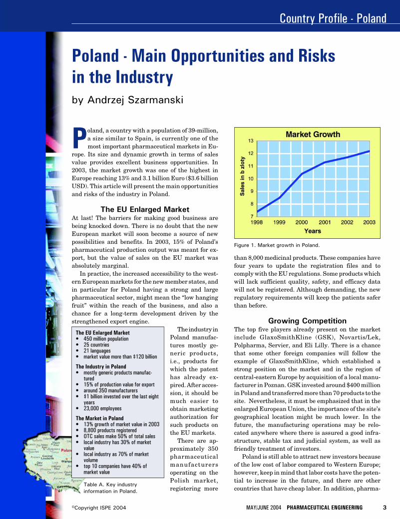
Poland, a country with a population of 39-million,a size similar to Spain, is currently one of themost important pharmaceutical markets in Eu-
rope. Its size and dynamic growth in terms of salesvalue provides excellent business opportunities. In2003, the market growth was one of the highest inEurope reaching 13% and 3.1 billion Euro ($3.6 billionUSD). This article will present the main opportunitiesand risks of the industry in Poland.
The EU Enlarged MarketAt last! The barriers for making good business arebeing knocked down. There is no doubt that the newEuropean market will soon become a source of newpossibilities and benefits. In 2003, 15% of Poland’spharmaceutical production output was meant for ex-port, but the value of sales on the EU market wasabsolutely marginal.
In practice, the increased accessibility to the west-ern European markets for the new member states, andin particular for Poland having a strong and largepharmaceutical sector, might mean the “low hangingfruit” within the reach of the business, and also achance for a long-term development driven by thestrengthened export engine.
The industry inPoland manufac-tures mostly ge-neric products,i.e., products forwhich the patenthas already ex-pired. After acces-sion, it should bemuch easier toobtain marketingauthorization forsuch products onthe EU markets.
There are ap-proximately 350pharmaceuticalmanufacturersoperating on thePolish market,registering more
Poland - Main Opportunities and Risksin the Industryby Andrzej Szarmanski
Figure 1. Market growth in Poland.
than 8,000 medicinal products. These companies havefour years to update the registration files and tocomply with the EU regulations. Some products whichwill lack sufficient quality, safety, and efficacy datawill not be registered. Although demanding, the newregulatory requirements will keep the patients saferthan before.
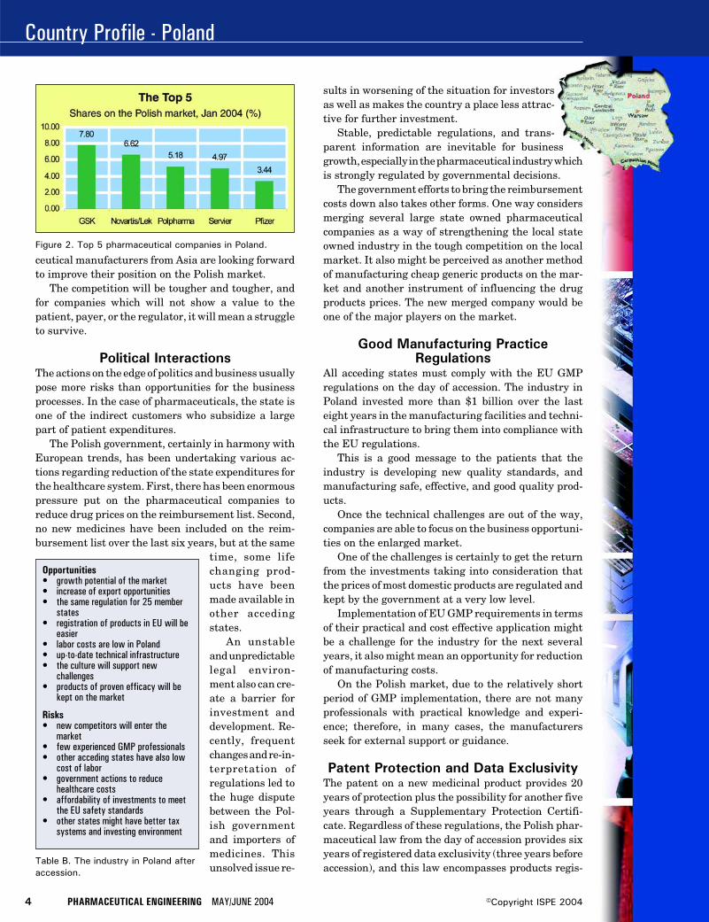
Growing CompetitionThe top five players already present on the marketinclude GlaxoSmithKline (GSK), Novartis/Lek,Polpharma, Servier, and Eli Lilly. There is a chancethat some other foreign companies will follow theexample of GlaxoSmithKline, which established astrong position on the market and in the region ofcentral-eastern Europe by acquisition of a local manu-facturer in Poznan. GSK invested around $400 millionin Poland and transferred more than 70 products to thesite. Nevertheless, it must be emphasized that in theenlarged European Union, the importance of the site’sgeographical location might be much lower. In thefuture, the manufacturing operations may be relo-cated anywhere where there is assured a good infra-structure, stable tax and judicial system, as well asfriendly treatment of investors.
Poland is still able to attract new investors becauseof the low cost of labor compared to Western Europe;however, keep in mind that labor costs have the poten-tial to increase in the future, and there are othercountries that have cheap labor. In addition, pharma-
Country Profile - Poland
4 PHARMACEUTICAL ENGINEERING MAY/JUNE 2004 ©Copyright ISPE 2004
Figure 2. Top 5 pharmaceutical companies in Poland.
Opportunities• growth potential of the market• increase of export opportunities• the same regulation for 25 member
states• registration of products in EU will be
easier• labor costs are low in Poland• up-to-date technical infrastructure• the culture will support new
challenges• products of proven efficacy will be
kept on the market
Risks• new competitors will enter the
market• few experienced GMP professionals• other acceding states have also low
cost of labor• government actions to reduce
healthcare costs• affordability of investments to meet
the EU safety standards• other states might have better tax
systems and investing environment
Table B. The industry in Poland afteraccession.
ceutical manufacturers from Asia are looking forwardto improve their position on the Polish market.
The competition will be tougher and tougher, andfor companies which will not show a value to thepatient, payer, or the regulator, it will mean a struggleto survive.
Political InteractionsThe actions on the edge of politics and business usuallypose more risks than opportunities for the businessprocesses. In the case of pharmaceuticals, the state isone of the indirect customers who subsidize a largepart of patient expenditures.
The Polish government, certainly in harmony withEuropean trends, has been undertaking various ac-tions regarding reduction of the state expenditures forthe healthcare system. First, there has been enormouspressure put on the pharmaceutical companies toreduce drug prices on the reimbursement list. Second,no new medicines have been included on the reim-bursement list over the last six years, but at the same
time, some lifechanging prod-ucts have beenmade available inother accedingstates.
An unstableand unpredictablelegal environ-ment also can cre-ate a barrier forinvestment anddevelopment. Re-cently, frequentchanges and re-in-terpretation ofregulations led tothe huge disputebetween the Pol-ish governmentand importers ofmedicines. Thisunsolved issue re-
sults in worsening of the situation for investorsas well as makes the country a place less attrac-tive for further investment.
Stable, predictable regulations, and trans-parent information are inevitable for businessgrowth, especially in the pharmaceutical industry whichis strongly regulated by governmental decisions.
The government efforts to bring the reimbursementcosts down also takes other forms. One way considersmerging several large state owned pharmaceuticalcompanies as a way of strengthening the local stateowned industry in the tough competition on the localmarket. It also might be perceived as another methodof manufacturing cheap generic products on the mar-ket and another instrument of influencing the drugproducts prices. The new merged company would beone of the major players on the market.
Good Manufacturing PracticeRegulations
All acceding states must comply with the EU GMPregulations on the day of accession. The industry inPoland invested more than $1 billion over the lasteight years in the manufacturing facilities and techni-cal infrastructure to bring them into compliance withthe EU regulations.
This is a good message to the patients that theindustry is developing new quality standards, andmanufacturing safe, effective, and good quality prod-ucts.
Once the technical challenges are out of the way,companies are able to focus on the business opportuni-ties on the enlarged market.
One of the challenges is certainly to get the returnfrom the investments taking into consideration thatthe prices of most domestic products are regulated andkept by the government at a very low level.
Implementation of EU GMP requirements in termsof their practical and cost effective application mightbe a challenge for the industry for the next severalyears, it also might mean an opportunity for reductionof manufacturing costs.
On the Polish market, due to the relatively shortperiod of GMP implementation, there are not manyprofessionals with practical knowledge and experi-ence; therefore, in many cases, the manufacturersseek for external support or guidance.
Patent Protection and Data ExclusivityThe patent on a new medicinal product provides 20years of protection plus the possibility for another fiveyears through a Supplementary Protection Certifi-cate. Regardless of these regulations, the Polish phar-maceutical law from the day of accession provides sixyears of registered data exclusivity (three years beforeaccession), and this law encompasses products regis-
Country Profile - Poland
MAY/JUNE 2004 PHARMACEUTICAL ENGINEERING 5©Copyright ISPE 2004
tered back to 1 January 2000. There are plans toextend the exclusivity data protection up to 10 yearsacross Europe which triggers a strong discussion re-garding different views.
Bringing a new medicinal product on the marketinvolves huge investments reaching in the hundredmillion dollar range. The longer new patented prod-ucts are protected by law, the more chances are forreturn on investments. This in turn allows for re-investing the revenues into research and potentialnew drug products, bringing value to the patients andchanging their lives.
The CultureChange was a close friend of the industry in Polandover the last decade. A reform of the pharmaceuticallaw, huge investments in the pharmaceutical sector,inflow of foreign investors, and know-how contributedto the culture change in the industry.
After 10 years of continuous changes, resultingchange is easier to swallow. Therefore, the advantageand also the opportunity of the Polish industry is thatthe country is prepared to deal with change manage-ment and experienced at doing business in a muchmore complex environment. Growing competition hasalready made many of the local manufacturers imple-ment new management techniques, lean manufactur-ing, and new organizational solutions. As a result,pharmaceutical manufacturers seem to be competingon the enlarged European market, and thriving at it.
About the AuthorAndrzej Szarmanski is the Quality Director at theGlaxoSmithKline site in Poznan, Poland and ViceChairman of the ISPE Poland Affiliate. E-mail:[email protected].
ISPE in Polandby Andrzej Szarmanski
The Poland Affiliate was established in 2001.The organization, although relatively new,
having many excellent specialists and manag-ers, makes a good platform for development andcooperation of industry professionals. There havebeen already several meetings organized by ISPEPoland to promote and facilitate training, pro-fessional effectiveness, and links between mem-bers. ISPE in Poland as a part of the interna-tional organization is open to cooperation withlocal regulatory authorities which may be par-ticularly valuable after EU enlargement.
ISPE Poland Officers
ChairmanMarek RuzikowskiUNIA, Co-operative WorksTel: +48 (0) 22 6203392Fax: +48 (0) 22 6549240E-mail: [email protected]
Vice ChairmanAndrzej SzarmanskiGlaxoSmithKline Pharmaceuticals S.A.Tel: +48 (0) 61 8673311Fax: +48 (0) 61 8601780E-mail: [email protected]
SecretaryBarbara Kawalko-MyslinskaCentre of Scientific Information “POLFA””Tel: +48 (0) 22 6160920Fax: +48 (0) 22 6160976E-mail: [email protected]
TreasurerAndrzej TyralaWarsaw Pharmaceutical Works “POLFA”Tel: +48 (0) 22 8224541Fax: +48 (0) 22 8233026E-mail: [email protected]
Country Profile - Poland
6 PHARMACEUTICAL ENGINEERING MAY/JUNE 2004 ©Copyright ISPE 2004
Continued market growth, wholesale privatizationof domestic companies, investment by leadinginternational groups, consolidation occurring in
the distribution channels, and major restructuring ofthe funding of the Polish healthcare system add up toPoland being one of Europe’s most dynamic and chal-lenging environments for the pharmaceutical industry.
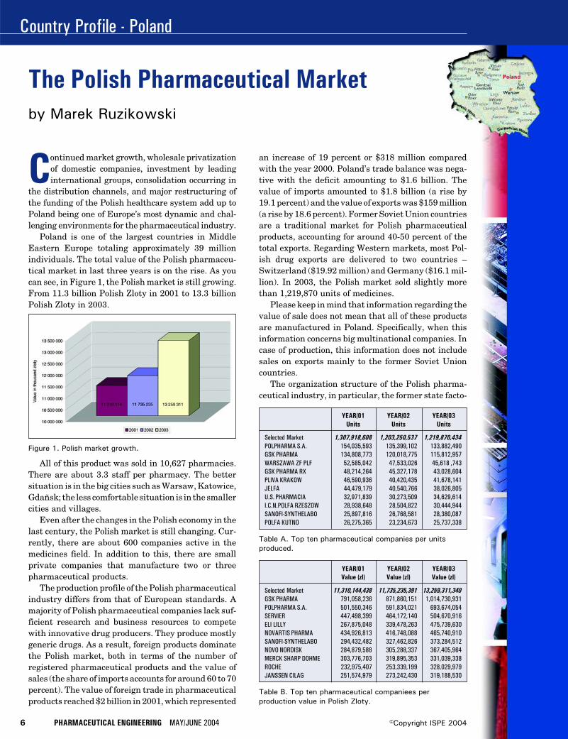
Poland is one of the largest countries in MiddleEastern Europe totaling approximately 39 millionindividuals. The total value of the Polish pharmaceu-tical market in last three years is on the rise. As youcan see, in Figure 1, the Polish market is still growing.From 11.3 billion Polish Zloty in 2001 to 13.3 billionPolish Zloty in 2003.
All of this product was sold in 10,627 pharmacies.There are about 3.3 staff per pharmacy. The bettersituation is in the big cities such as Warsaw, Katowice,Gdañsk; the less comfortable situation is in the smallercities and villages.
Even after the changes in the Polish economy in thelast century, the Polish market is still changing. Cur-rently, there are about 600 companies active in themedicines field. In addition to this, there are smallprivate companies that manufacture two or threepharmaceutical products.
The production profile of the Polish pharmaceuticalindustry differs from that of European standards. Amajority of Polish pharmaceutical companies lack suf-ficient research and business resources to competewith innovative drug producers. They produce mostlygeneric drugs. As a result, foreign products dominatethe Polish market, both in terms of the number ofregistered pharmaceutical products and the value ofsales (the share of imports accounts for around 60 to 70percent). The value of foreign trade in pharmaceuticalproducts reached $2 billion in 2001, which represented
an increase of 19 percent or $318 million comparedwith the year 2000. Poland’s trade balance was nega-tive with the deficit amounting to $1.6 billion. Thevalue of imports amounted to $1.8 billion (a rise by19.1 percent) and the value of exports was $159 million(a rise by 18.6 percent). Former Soviet Union countriesare a traditional market for Polish pharmaceuticalproducts, accounting for around 40-50 percent of thetotal exports. Regarding Western markets, most Pol-ish drug exports are delivered to two countries –Switzerland ($19.92 million) and Germany ($16.1 mil-lion). In 2003, the Polish market sold slightly morethan 1,219,870 units of medicines.
Please keep in mind that information regarding thevalue of sale does not mean that all of these productsare manufactured in Poland. Specifically, when thisinformation concerns big multinational companies. Incase of production, this information does not includesales on exports mainly to the former Soviet Unioncountries.
The organization structure of the Polish pharma-ceutical industry, in particular, the former state facto-
The Polish Pharmaceutical Market
Figure 1. Polish market growth.
YEAR/01 YEAR/02 YEAR/03Value (zl) Value (zl) Value (zl)
Selected Market 11,310,144,438 11,735,235,391 13,259,311,340GSK PHARMA 791,058,236 871,860,151 1,014,730,931POLPHARMA S.A. 501,550,346 591,834,021 693,674,054SERVIER 447,498,399 464,172,140 504,670,916ELI LILLY 267,875,048 339,478,263 475,739,630NOVARTIS PHARMA 434,926,813 416,748,088 465,740,910SANOFI-SYNTHELABO 294,432,482 327,462,826 373,284,512NOVO NORDISK 284,879,588 305,288,337 367,405,964MERCK SHARP DOHME 303,776,703 319,895,353 331,039,338ROCHE 232,975,407 253,339,199 328,029,979JANSSEN CILAG 251,574,979 273,242,430 319,188,530
Table B. Top ten pharmaceutical companiees perproduction value in Polish Zloty.
YEAR/01 YEAR/02 YEAR/03Units Units Units
Selected Market 1,307,918,608 1,203,250,537 1,219,870,434POLPHARMA S.A. 154,035,593 135,399,102 133,882,490GSK PHARMA 134,808,773 120,018,775 115,812,957WARSZAWA ZF PLF 52,585,042 47,533,026 45,618 ,743GSK PHARMA RX 48,214,264 45,327,178 43,028,604PLIVA KRAKOW 46,590,936 40,420,435 41,678,141JELFA 44,479,179 40,540,766 38,026,805U.S. PHARMACIA 32,971,839 30,273,509 34,629,614I.C.N.POLFA RZESZOW 28,938,648 28,504,822 30,444,944SANOFI-SYNTHELABO 25,897,816 26,768,581 28,380,087POLFA KUTNO 26,275,365 23,234,673 25,737,338
Table A. Top ten pharmaceutical companies per unitsproduced.
by Marek Ruzikowski
Country Profile - Poland
MAY/JUNE 2004 PHARMACEUTICAL ENGINEERING 7©Copyright ISPE 2004
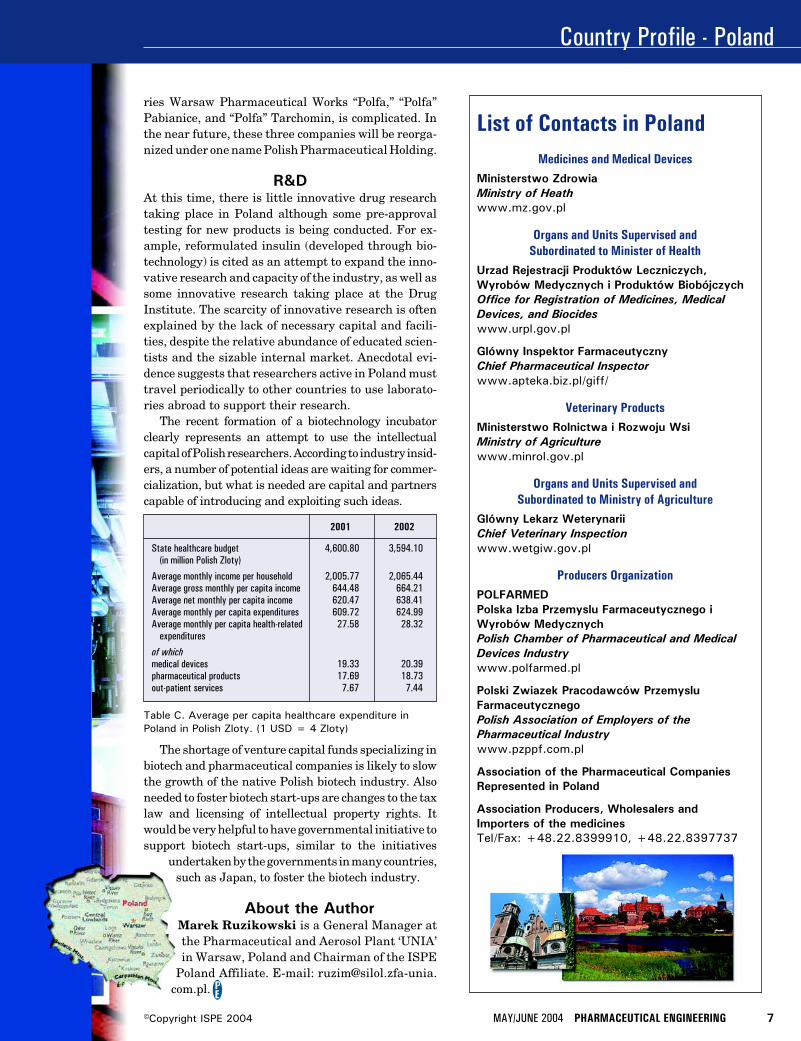
Table C. Average per capita healthcare expenditure inPoland in Polish Zloty. (1 USD = 4 Zloty)
2001 2002
State healthcare budget 4,600.80 3,594.10(in million Polish Zloty)
Average monthly income per household 2,005.77 2,065.44Average gross monthly per capita income 644.48 664.21Average net monthly per capita income 620.47 638.41Average monthly per capita expenditures 609.72 624.99Average monthly per capita health-related 27.58 28.32
expenditures
of whichmedical devices 19.33 20.39pharmaceutical products 17.69 18.73out-patient services 7.67 7.44
ries Warsaw Pharmaceutical Works “Polfa,” “Polfa”Pabianice, and “Polfa” Tarchomin, is complicated. Inthe near future, these three companies will be reorga-nized under one name Polish Pharmaceutical Holding.
R&DAt this time, there is little innovative drug researchtaking place in Poland although some pre-approvaltesting for new products is being conducted. For ex-ample, reformulated insulin (developed through bio-technology) is cited as an attempt to expand the inno-vative research and capacity of the industry, as well assome innovative research taking place at the DrugInstitute. The scarcity of innovative research is oftenexplained by the lack of necessary capital and facili-ties, despite the relative abundance of educated scien-tists and the sizable internal market. Anecdotal evi-dence suggests that researchers active in Poland musttravel periodically to other countries to use laborato-ries abroad to support their research.
The recent formation of a biotechnology incubatorclearly represents an attempt to use the intellectualcapital of Polish researchers. According to industry insid-ers, a number of potential ideas are waiting for commer-cialization, but what is needed are capital and partnerscapable of introducing and exploiting such ideas.
The shortage of venture capital funds specializing inbiotech and pharmaceutical companies is likely to slowthe growth of the native Polish biotech industry. Alsoneeded to foster biotech start-ups are changes to the taxlaw and licensing of intellectual property rights. Itwould be very helpful to have governmental initiative tosupport biotech start-ups, similar to the initiatives
undertaken by the governments in many countries,such as Japan, to foster the biotech industry.
About the AuthorMarek Ruzikowski is a General Manager atthe Pharmaceutical and Aerosol Plant ‘UNIA’in Warsaw, Poland and Chairman of the ISPE
Poland Affiliate. E-mail: [email protected].
List of Contacts in PolandMedicines and Medical Devices
Ministerstwo ZdrowiaMinistry of Heathwww.mz.gov.pl
Organs and Units Supervised andSubordinated to Minister of Health
Urzad Rejestracji Produktów Leczniczych,Wyrobów Medycznych i Produktów BiobójczychOffice for Registration of Medicines, MedicalDevices, and Biocideswww.urpl.gov.pl
Glówny Inspektor FarmaceutycznyChief Pharmaceutical Inspectorwww.apteka.biz.pl/giff/
Veterinary ProductsMinisterstwo Rolnictwa i Rozwoju WsiMinistry of Agriculturewww.minrol.gov.pl
Organs and Units Supervised andSubordinated to Ministry of Agriculture
Glówny Lekarz WeterynariiChief Veterinary Inspectionwww.wetgiw.gov.pl
Producers OrganizationPOLFARMEDPolska Izba Przemyslu Farmaceutycznego iWyrobów MedycznychPolish Chamber of Pharmaceutical and MedicalDevices Industrywww.polfarmed.pl
Polski Zwiazek Pracodawców PrzemysluFarmaceutycznegoPolish Association of Employers of thePharmaceutical Industrywww.pzppf.com.pl
Association of the Pharmaceutical CompaniesRepresented in Poland
Association Producers, Wholesalers andImporters of the medicinesTel/Fax: +48.22.8399910, +48.22.8397737
Computational Fluid Dynamics
MAY/JUNE 2004 PHARMACEUTICAL ENGINEERING 1©Copyright ISPE 2004
ment. However, in order to determine the rami-fications of genetic implants, a live field trialcould become the possible cause of one suchdisaster by its very application.1 Even withstrict regulations and tough rules imposed bythe US Department of Agriculture, Animal andPlant Health Inspection Service (APHIS), con-tamination of natural species by geneticallymodified crops has occurred. To ensure thepurity of the natural species, transgenic cropsdeveloped for their pharmaceutical value(pharma crops) must be sufficiently excludedfrom the natural belts of the parent species.2
Therefore, a numerical simulation of plant pol-lination dynamics should be developed to pre-dict the behavior of the natural system.
Methods forProducing andCharacteristicsof Transgenic
CropsCreating geneticallymodified plants in-volves cutting edgetechnology that focuseson engineering theplant species in orderto obtain the desiredcharacteristics. Theprocess of genetic alter-ation is achieved by in-troducing foreign genesinto the plant genome.The subsequent expres-sion of these transgenesto a satisfactory extentresults in a geneticallymodified plant.3
Agro bacterium as agene vector has beenused since the early
Numerical Simulation of GeneticallyModified Corn Pollen Flowby Brian A. Fricke, PhD, Arun K. Ranjan,Deep Bandyopadhyay, and Bryan R. Becker, PhD, PE
Introduction
Due to numerous advances made in thefield of biotechnology, genetically modi-fied or transgenic crops have been de-veloped for their pharmaceutical value
or with beneficial characteristics such as herbi-cide tolerance or disease resistance. However,the possible repercussions of human interven-tion in nature should not go unchecked whenevaluating the numerous benefits which couldbe derived from genetically modifying crops.The most immediate risk posed by transgeniccrops is that of cross-pollination between thegenetically modified species and the naturalspecies, the implications of which suggest seri-ous modifications in the surrounding environ-
In this articleComputationalFluid Dynamics(CFD) softwarewas used toestimate thedistancestraversed bytransgenic cornpollen.
Arun K. Ranjan, agraduate studentand ISPE studentmember at theUniversity ofMissouri-KansasCity, won thegraduate levelaward at the ISPEMidwest Chapter’sStudent PosterCompetition in thespring of 2003.This awardconsisted ofsponsorship to theISPE AnnualMeeting inNovember 2003where he competedwith other localwinners in theInternational PosterCompetition.
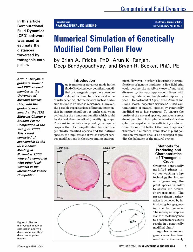
Figure 1. Electronmicroscope image ofcorn pollen and twodimensional and threedimensional pollenmodels.
Reprinted from The Official Journal of ISPE
PHARMACEUTICAL ENGINEERING® May/June 2004, Vol. 24 No. 3
Computational Fluid Dynamics
2 PHARMACEUTICAL ENGINEERING MAY/JUNE 2004 ©Copyright ISPE 2004
stages of biotechnology for successful gene transfers. In thistechnique, an expression of interest is inserted into the Agrobacterium plasmid, which in turn inserts the genetic mate-rial into the DNA of the host plant after crossing the plant cellbarrier. These modified cells then develop into transgenicplants. However, this method cannot be used for all types ofplant families. For example, monocots are difficult to hybrid-ize by this method because agro bacteria generally infectdicots and do not easily form pathogens necessary for infect-ing the monocots.
The technique of electroporation has been used for manyyears and it uses electrical current to open pores or tiny holesin the plant membrane to allow transfer of genetic materialinto the cell. Although this technique is simple, it is onlyapplicable to grasses such as wheat, rice, or lettuce.
The technique of micro-projectile transfer employs bits ofgenetic material that can be attached to tiny spheres, whichare then shot into selected plant cells for hybridization. Corncan be converted into a transgenic crop by this method.
A current technique involves in-vitro manipulation of acrop’s tissue culture by micro injecting DNA directly into thenucleus. Recent technological advances have made possiblethe use of recombinant DNA techniques in which interestspecific gene transfer occurs without causing backcrossing ofnew genes into nature. This technique can be effectively usedfor genetic expression of characteristics between totally un-related species; plants and animals are thus mutually com-prehendible. Clever manipulation of any of the aforemen-tioned techniques can generate transgenic plants with morethan one trait of interest.
Almost all genetically modified plants have at least onemarker gene inserted into their genetic makeup to provide
traits of interest. Common traits generally altered by inser-tion of marker genes include herbicide tolerance, insectresistance, disease resistance, stress tolerance, and physi-ological occurrence. Crops also may be genetically modified toenhance nutrition and taste, extend shelf life, and easestorage as well as provide attractive appearance. Some of themore valuable products to have been developed from geneti-cally modified plants include drugs which have the potentialto cure rare diseases, i.e., alpha-galactosidase andglucocerebrosidase used to treat Fabry’s and Gaucher’s dis-eases. Special proteins known as defensins also are beingproduced from pharma crops to obtain alternative antibiot-ics. With such techniques and traits, it is possible for atransgenic crop, which is tolerant to saline conditions to becultivated in agricultural wastelands and create economicopportunities, which would otherwise be non-existent.
However, hybridized plants are capable of transferringtheir genes over long distances to related plants, which havedifferent characteristics. Therefore, engineered plants, withinserted experimental or engineered genes, may find a com-patible relative and transfer their code to the natural spe-cies.4-12
Environmental Impact of Transgenic CropsWhile the advent of new technologies provides us with theability to enhance particular traits, this technology also maycreate significant problems that can be of major concern ifunchecked. It is an absolute certainty that fertilization willoccur between naturally occurring plants that are in thevicinity of transgenic plants.
The event of fertilization depends on factors such as sexualcompatibility of the genetically modified plant and the wild
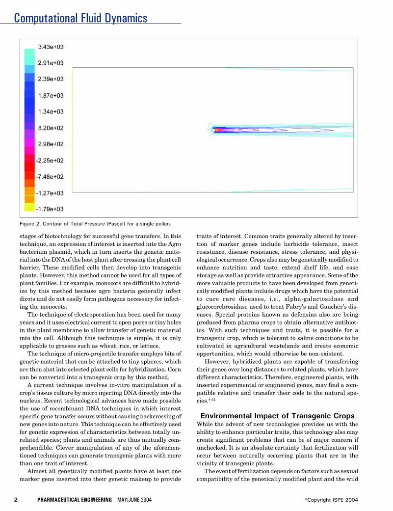
Figure 2. Contour of Total Pressure (Pascal) for a single pollen.
Computational Fluid Dynamics
MAY/JUNE 2004 PHARMACEUTICAL ENGINEERING 3©Copyright ISPE 2004
relative, geographical occurrence, natural vectors of pollina-tion, and identical fertilization seasons. In spite of so manyrequirements for successful mating, cross breeding has oc-curred in nature, and hence, the problem of genetic transferto the wild species is genuine. Cross breeding would result indominant wild relatives with traits acquired from the geneti-cally modified species, and these wild relatives would becomesuper weeds whose elimination would become difficult.13,14
This also means that loss of biodiversity and significantevolutionary changes are inevitable and will eventually re-sult in the modification of the total genetic informationpresent in a breeding population or species.
The problem of hybridization is not limited to containingfertilization between a transgenic crop and a wild relative.The transfer or genetic fallout of transgenes to different plantpopulations has a higher probability of occurring dependingon the economic value of the transgenic crop.15 Such sponta-neous hybridization can lead to the extinction of rare speciesof plants, animals, or insects, which would have otherwisebeen left undisturbed.
Given the adaptability that transgenic crops can be be-stowed with, planting them in unnatural geographical loca-tions raises the risk of contamination considerably.16 Forinstance, introgression of transgenic DNA into natural croplandraces for growing maize in the remote mountains ofOaxaca, Mexico has been reported.17 In addition, transgenicpollen has been shown to cause considerable harm to rareinsect species. For example, pollen from Bt corn, which is agenetically modified form of corn with pesticidal qualities,has been found to be harmful to the larvae of the monarchbutterfly.18
Field trials involving measurement of natural fertiliza-tion of wild radish (Raphanus Sativus), a weed, with culti-
vated radish containing the allozyme allele (Lap-6) yieldedcontamination at considerable distances. This gives rise tothe important question of whether engineered crops can findtheir way into the food chain. As further evidence, theStarlink Cry9C allele was found occurring in natural cornmeant for human consumption. This clearly indicates theneed for accurate measurements and preventive measures toavoid such mishaps.19
The Board on Agriculture and Natural Resources (BANR),under the aegis of National Research Council (NRC), hasplaced emphasis on research for studying post gene floweffects from transgenic plants resulting in the release ofallergens, toxins, development of resistant pests, and theeffect on unintended target species. It also acknowledges thatwhile the techniques developed are safe, the hazards posedare worth analyzing.20
Transgenic CornAmong the world’s 13 most important crops, maize or cornranks second in terms of cultivation and consumption.21 Thebotanical definition of corn is:22
Family: PoaceaeGenus: Zea (ZEE-uh)Species: mays (maze)Category: VegetablesSeed Type: Open PollinatedDays to Maturity: 81 to 90 daysHeight: 4-6 ft. (1.2-1.8 m), 6-8 ft. (1.8-2.4 m)Spacing: 6-9 in. (15-22 cm), 9-12 in. (22-30 cm)Kernel Color: Red, Yellow, Blue-VioletSoil pH requirements: 6.6 to 7.5 (neutral)
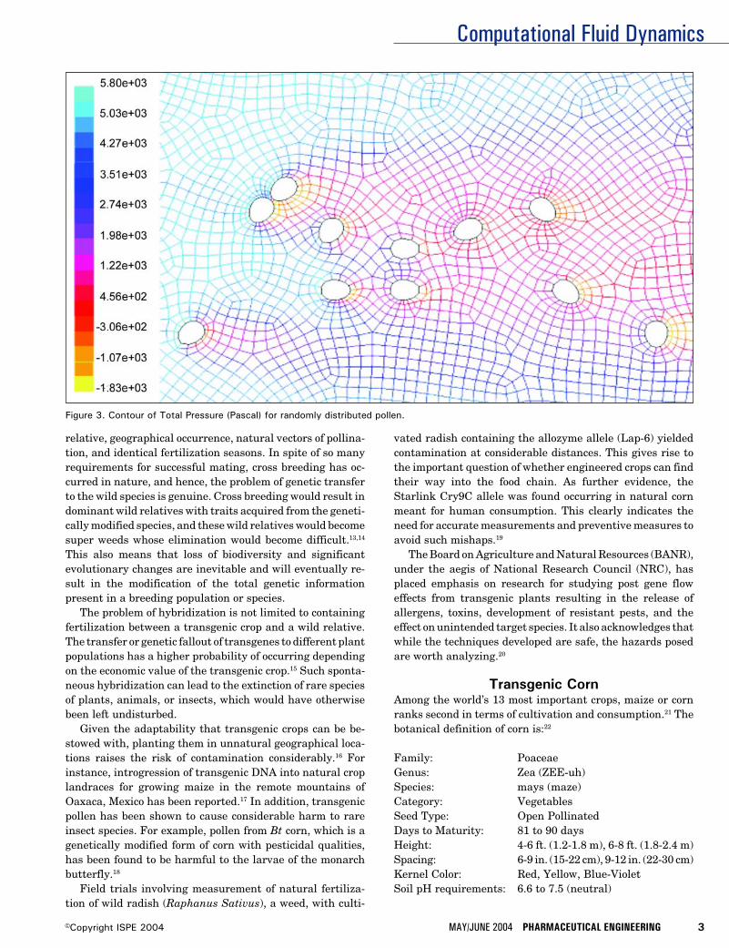
Figure 3. Contour of Total Pressure (Pascal) for randomly distributed pollen.
Computational Fluid Dynamics
4 PHARMACEUTICAL ENGINEERING MAY/JUNE 2004 ©Copyright ISPE 2004
One of the most prominent genetically modified crops is BtCorn, which contains genes inserted from BacillusThuringiensis, a soil bacterium producing crystal proteintoxins capable of eliminating pests. While Bt Corn reducesthe use of pesticides, it also is proving to be harmful forseveral insect orders.
Due to the high level of cultivation and consumption ofcorn, and since corn is open pollinated, the potential forgenetic pollution is high when compared to other crops.23 Theidentification of genetically modified corn transcending overthe genetic pool of traditional corn has caused controversy.Research conducted on obtaining molecular evidence forgenetic flow in the species has provided proof that gene flowdoes indeed occur between corn and its wild relative teosinte,which may engulf entire teosinte populations.24,25 Studieshave shown that pollen dispersal and pollen activity betweengenetically modified and natural corn crops depends upon theamount of pollen released and the distance between them.26
Transgenic corn is introduced into the natural species viapollen flow. However, very little is known about the mecha-nism of pollen movement. Further, the impact of variousweather patterns and wind conditions upon pollen flow is notknown.27 It is proposed to simulate pollination dynamics withComputational Fluid Dynamics (CFD) software to determinepollen trajectories and distance traversed. The results of suchsimulations will provide insight into the mechanism of pollenflow behavior and guidance for estimating safe distances forplanting genetically modified corn from the natural species.
Computational ModelThe objective of this research was to use CFD software28 todetermine the distance traversed by the genetically modifiedcorn pollen under different environmental conditions. TheCFD software solves the governing integral equations forconservation of mass and momentum, and when appropriate,for energy and other scalars such as turbulence and chemicalspecies. A control-volume-based technique is used to obtainsolutions to the governing integral equations, and consists ofthe following steps:
• division of the domain into discrete control volumes usinga computational grid
• integration of the governing equations on the individualcontrol volumes to construct algebraic equations for thediscrete, unknown dependent variables such as velocities,pressure, temperature, and conserved scalars
• linearization of the discretized equations and solution ofthe resultant linear system of equations to yield updatedvalues of the dependent variables
Governing EquationsThe equation for conservation of mass, or the continuityequation, can be written as follows:
∂ρ →___ + ∇.(ρν) = Sm (1)∂t
→where ρ is density, t is time, ν is velocity and Sm is the masssource term which may include the mass added to the con-tinuous phase from a dispersed second phase, e.g., vaporiza-tion of liquid droplets, and/or from any user-defined sources.This equation is the general form of the mass conservationequation and is valid for incompressible as well as compress-ible flows.
For two-dimensional axisymmetric geometries, Equation(1) one can be written as:
∂ρ ∂ ∂ ρνr___ + ___ (ρνx) + ___ (ρνr) + ___ = Sm (2)∂t ∂x ∂r r
where x is the axial coordinate, r is the radial coordinate, νx
is the axial velocity, and νr is the radial velocity.Conservation of momentum in an inertial, non-accelerat-
ing, reference frame is given as:29
∂ → →→ = → →___ (ρν) + ∇.(ρνν) = -∇p + ∇.(τ) + ρg + F (3)∂t
= →where p is the static pressure, τ is the stress tensor, ρg is the
→gravitational body force and F is the external body forcewhich may contain model-dependent source terms such asporous-media and user-defined sources.
=The stress tensor τ is given by:
= → → 2 →τ = µ [(∇ν + ∇νT) - __ ∇.νI ] (4)
3
where µ is the molecular viscosity, I is the unit tensor, and thesecond term on the right hand side is the effect of volumedilation.
For two-dimensional axisymmetric geometries, the con-servation of momentum equation in the axial direction isgiven as:
∂ 1 ∂ 1 ∂ ∂p 1 ∂___ (ρνx) + __ ___ (rρνxνx) + __ ___ (rρνrνx) = - ___ + __ ___∂t r ∂x r ∂r ∂x r ∂x
∂νx 2 → 1 ∂ ∂νx ∂νr[rµ(2 ___ - __ (∇.ν))] + __ ___ [rµ(___ + ___)] + Fx (3)
∂x 3 r ∂r ∂r ∂x
while the conservation of momentum equation in radialdirection is given as:
∂ 1 ∂ 1 ∂ ∂p 1 ∂___ (ρνr) + __ ___ (rρνxνr) + __ ___ (rρνrνr) = - ___ + __ ___∂t r ∂x r ∂r ∂r r ∂x
∂νr ∂νx 1 ∂ ∂νr 2 → νr 2 µ[rµ(___ + ___)] + __ ___ [rµ(2 ___ - __ (∇.ν))] - 2µ ___ + __ __
∂x ∂r r ∂x ∂r 3 r2 3 r
→ νz2
(∇.ν) + ρ ___ + Fr (4)r
where
→ ∂νx ∂νr νr∇.ν = ___ + ___ + ___∂x ∂r r
and νz is the swirl velocity.
Computational Fluid Dynamics
MAY/JUNE 2004 PHARMACEUTICAL ENGINEERING 5©Copyright ISPE 2004
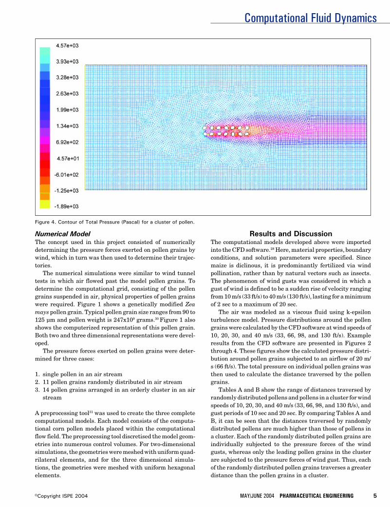
Figure 4. Contour of Total Pressure (Pascal) for a cluster of pollen.
Numerical ModelThe concept used in this project consisted of numericallydetermining the pressure forces exerted on pollen grains bywind, which in turn was then used to determine their trajec-tories.
The numerical simulations were similar to wind tunneltests in which air flowed past the model pollen grains. Todetermine the computational grid, consisting of the pollengrains suspended in air, physical properties of pollen grainswere required. Figure 1 shows a genetically modified Zeamays pollen grain. Typical pollen grain size ranges from 90 to125 µm and pollen weight is 247x109 grams.30 Figure 1 alsoshows the computerized representation of this pollen grain.Both two and three dimensional representations were devel-oped.
The pressure forces exerted on pollen grains were deter-mined for three cases:
1. single pollen in an air stream2. 11 pollen grains randomly distributed in air stream3. 14 pollen grains arranged in an orderly cluster in an air
stream
A preprocessing tool31 was used to create the three completecomputational models. Each model consists of the computa-tional corn pollen models placed within the computationalflow field. The preprocessing tool discretised the model geom-etries into numerous control volumes. For two-dimensionalsimulations, the geometries were meshed with uniform quad-rilateral elements, and for the three dimensional simula-tions, the geometries were meshed with uniform hexagonalelements.
Results and DiscussionThe computational models developed above were importedinto the CFD software.28 Here, material properties, boundaryconditions, and solution parameters were specified. Sincemaize is diclinous, it is predominantly fertilized via windpollination, rather than by natural vectors such as insects.The phenomenon of wind gusts was considered in which agust of wind is defined to be a sudden rise of velocity rangingfrom 10 m/s (33 ft/s) to 40 m/s (130 ft/s), lasting for a minimumof 2 sec to a maximum of 20 sec.
The air was modeled as a viscous fluid using k-epsilonturbulence model. Pressure distributions around the pollengrains were calculated by the CFD software at wind speeds of10, 20, 30, and 40 m/s (33, 66, 98, and 130 ft/s). Exampleresults from the CFD software are presented in Figures 2through 4. These figures show the calculated pressure distri-bution around pollen grains subjected to an airflow of 20 m/s (66 ft/s). The total pressure on individual pollen grains wasthen used to calculate the distance traversed by the pollengrains.
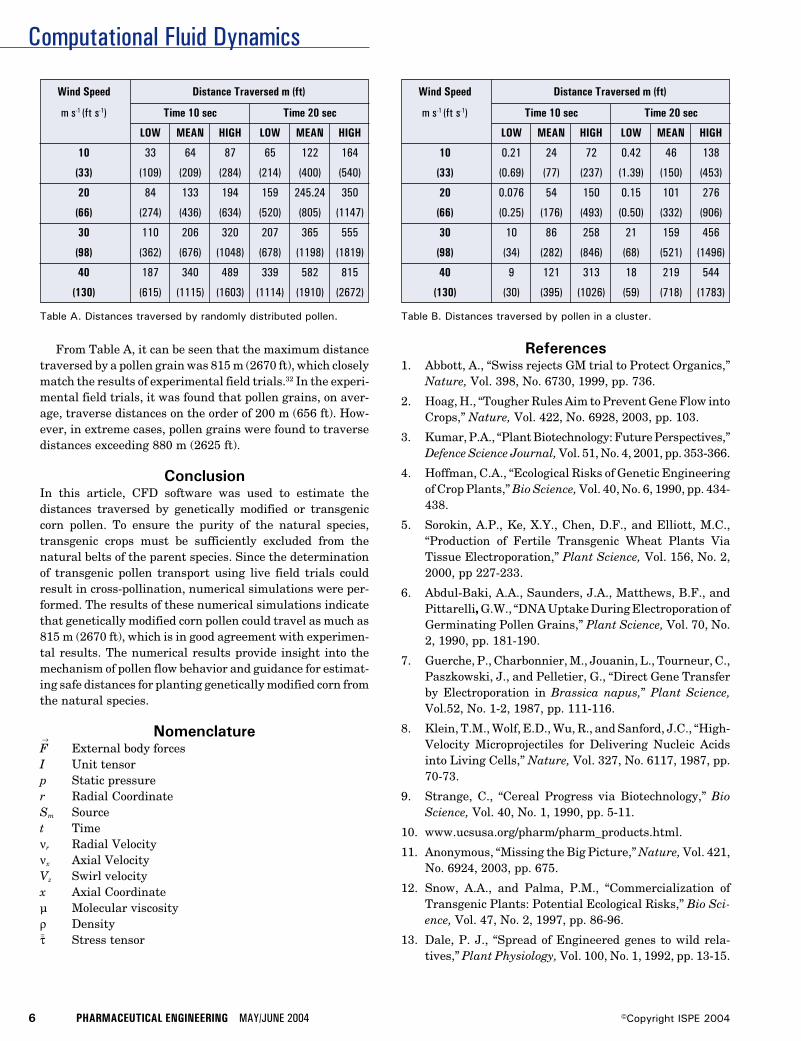
Tables A and B show the range of distances traversed byrandomly distributed pollens and pollens in a cluster for windspeeds of 10, 20, 30, and 40 m/s (33, 66, 98, and 130 ft/s), andgust periods of 10 sec and 20 sec. By comparing Tables A andB, it can be seen that the distances traversed by randomlydistributed pollens are much higher than those of pollens ina cluster. Each of the randomly distributed pollen grains areindividually subjected to the pressure forces of the windgusts, whereas only the leading pollen grains in the clusterare subjected to the pressure forces of wind gust. Thus, eachof the randomly distributed pollen grains traverses a greaterdistance than the pollen grains in a cluster.
Computational Fluid Dynamics
6 PHARMACEUTICAL ENGINEERING MAY/JUNE 2004 ©Copyright ISPE 2004
Wind Speed Distance Traversed m (ft)
m s-1 (ft s-1) Time 10 sec Time 20 sec
LOW MEAN HIGH LOW MEAN HIGH
10 33 64 87 65 122 164
(33) (109) (209) (284) (214) (400) (540)
20 84 133 194 159 245.24 350
(66) (274) (436) (634) (520) (805) (1147)
30 110 206 320 207 365 555
(98) (362) (676) (1048) (678) (1198) (1819)
40 187 340 489 339 582 815
(130) (615) (1115) (1603) (1114) (1910) (2672)
Table A. Distances traversed by randomly distributed pollen. Table B. Distances traversed by pollen in a cluster.
Wind Speed Distance Traversed m (ft)
m s-1 (ft s-1) Time 10 sec Time 20 sec
LOW MEAN HIGH LOW MEAN HIGH
10 0.21 24 72 0.42 46 138
(33) (0.69) (77) (237) (1.39) (150) (453)
20 0.076 54 150 0.15 101 276
(66) (0.25) (176) (493) (0.50) (332) (906)
30 10 86 258 21 159 456
(98) (34) (282) (846) (68) (521) (1496)
40 9 121 313 18 219 544
(130) (30) (395) (1026) (59) (718) (1783)
From Table A, it can be seen that the maximum distancetraversed by a pollen grain was 815 m (2670 ft), which closelymatch the results of experimental field trials.32 In the experi-mental field trials, it was found that pollen grains, on aver-age, traverse distances on the order of 200 m (656 ft). How-ever, in extreme cases, pollen grains were found to traversedistances exceeding 880 m (2625 ft).
ConclusionIn this article, CFD software was used to estimate thedistances traversed by genetically modified or transgeniccorn pollen. To ensure the purity of the natural species,transgenic crops must be sufficiently excluded from thenatural belts of the parent species. Since the determinationof transgenic pollen transport using live field trials couldresult in cross-pollination, numerical simulations were per-formed. The results of these numerical simulations indicatethat genetically modified corn pollen could travel as much as815 m (2670 ft), which is in good agreement with experimen-tal results. The numerical results provide insight into themechanism of pollen flow behavior and guidance for estimat-ing safe distances for planting genetically modified corn fromthe natural species.
Nomenclature→F External body forcesI Unit tensorp Static pressurer Radial CoordinateSm Sourcet Timeνr Radial Velocityνx Axial VelocityVz Swirl velocityx Axial Coordinateµ Molecular viscosityρ Density=τ Stress tensor
References1. Abbott, A., “Swiss rejects GM trial to Protect Organics,”
Nature, Vol. 398, No. 6730, 1999, pp. 736.
2. Hoag, H., “Tougher Rules Aim to Prevent Gene Flow intoCrops,” Nature, Vol. 422, No. 6928, 2003, pp. 103.
3. Kumar, P.A., “Plant Biotechnology: Future Perspectives,”Defence Science Journal, Vol. 51, No. 4, 2001, pp. 353-366.
4. Hoffman, C.A., “Ecological Risks of Genetic Engineeringof Crop Plants,” Bio Science, Vol. 40, No. 6, 1990, pp. 434-438.
5. Sorokin, A.P., Ke, X.Y., Chen, D.F., and Elliott, M.C.,“Production of Fertile Transgenic Wheat Plants ViaTissue Electroporation,” Plant Science, Vol. 156, No. 2,2000, pp 227-233.
6. Abdul-Baki, A.A., Saunders, J.A., Matthews, B.F., andPittarelli, G.W., “DNA Uptake During Electroporation ofGerminating Pollen Grains,” Plant Science, Vol. 70, No.2, 1990, pp. 181-190.
7. Guerche, P., Charbonnier, M., Jouanin, L., Tourneur, C.,Paszkowski, J., and Pelletier, G., “Direct Gene Transferby Electroporation in Brassica napus,” Plant Science,Vol.52, No. 1-2, 1987, pp. 111-116.
8. Klein, T.M., Wolf, E.D., Wu, R., and Sanford, J.C., “High-Velocity Microprojectiles for Delivering Nucleic Acidsinto Living Cells,” Nature, Vol. 327, No. 6117, 1987, pp.70-73.
9. Strange, C., “Cereal Progress via Biotechnology,” BioScience, Vol. 40, No. 1, 1990, pp. 5-11.
10. www.ucsusa.org/pharm/pharm_products.html.
11. Anonymous, “Missing the Big Picture,” Nature, Vol. 421,No. 6924, 2003, pp. 675.
12. Snow, A.A., and Palma, P.M., “Commercialization ofTransgenic Plants: Potential Ecological Risks,” Bio Sci-ence, Vol. 47, No. 2, 1997, pp. 86-96.
13. Dale, P. J., “Spread of Engineered genes to wild rela-tives,” Plant Physiology, Vol. 100, No. 1, 1992, pp. 13-15.
Computational Fluid Dynamics
MAY/JUNE 2004 PHARMACEUTICAL ENGINEERING 7©Copyright ISPE 2004
14. Kaiser, J., “Breeding a Hardier Weed,” Science, Vol. 293,No. 5534, 2001, pp. 1425-1427.
15. Arriola, P.E., and Ellstrand, N.C., “Crop-T-Weed GeneFlow in the Genus Sorghum (Poaceae): SpontaneousInterspecific Hybridization Between Johnsongrass, Sor-ghum Halepense, and Crop Sorghum, S. Bicolor,” Ameri-can Journal of Botany, Vol. 83, No. 9, 1996, pp. 1153-1160.
16. Ellstrand, N.C., and Hoffman, C.A., “Hybridization as anAvenue for Engineered Genes,” Bio Science, Vol. 40, No.6, 1990, pp. 438-443.
17. Quest, D. and Chapela, I.H., “Transgenic DNAIntrogressed into Traditional Maize Landraces in Oaxaca,Mexico,” Nature, Vol. 414, No. 6863, 2001, pp. 541-543.
18. Losey, J.E., Rayor, L.S., and Carter, M.E., “TransgenicPollen Harms Monarch larvae,” Nature, Vol. 399, No.6733, 1999, pp. 214.
19. Ellstrand, N.C., “When Transgenes Wander, Should WeWorry,” Plant Physiology, Vol. 125, No. 4, 2001, pp. 1543-1545.
20. National Research Council (NRC) (2000), “GeneticallyModified Pest-Protected Plants: Science and Regula-tion,” National Academy Press, Washington, DC.
21. Ellstrand, N.C., Prentice, H.C., and Hancock, J.F., “GeneFlow and Introgression from Domesticated Plants intoTheir Wild Relatives,” Annual Review of Ecology andSystematics, Vol. 30, 1999, pp. 539-563.
22. http://plantsdatabase.com.
23. Gewin, V., “Genetically Modified Corn – EnvironmentalBenefits and Risks,” PLoS Biology, Vol. 1, No. 1, 2003, pp.015-019.
24. Butler, D., “Alleged Flaws in Gene – Transfer PaperSpark Row Over,” Nature, Vol. 415, No. 6875, 2002, pp.948.
25. Doebley, J., “Molecular Evidence for Gene Flow amongZea Species,” Bio Science, Vol. 40, No. 6, 1990, pp. 443-448.
26. Messeguer, J., “Gene Flow Assessment in TransgenicPlants,” International Journal on Biotechnology of HigherPlants, Vol. 73, No. 3, 2003, pp. 201-212.
27. Erickson, B.E., “Gene Transfer in the Environment,”Environmental Science and Technology, January 2001,pp. 20A-22A.
28. Fluent Incorporated, Fluent 6.0, Lebanon, NH 03766-1442.
29. Batchelor, G. K., “An Introduction to Fluid Dynamics,”Cambridge Univ. Press, Cambridge, England, 1967.
30. Loos, C., Seppelt, R., Meier-Bethke, S., Schiemann, J.,and Richter, O., “Spatially Explicit Modeling of TransgenicMaize Pollen Dispersal and Cross-Pollination,” Journalof Theoretical Biology, Vol. 225, No. 2, 2003, pp. 241-255.
31. Fluent Incorporated, GAMBIT, Lebanon, NH 03766-1442.
32. Eastham, K. and Sweet, J., “Genetically Modified Organ-isms (GMOs): The Significance of Gene Flow throughPollen Transfer,” European Environment Agency,Copenhagen, Denmark, Vol. 1, No. 28, 2002, pp. 38-42.
About the AuthorsBrian A. Fricke, PhD is an Assistant Pro-fessor of Mechanical Engineering in theSchool of Computing and Engineering at theUniversity of Missouri-Kansas City. His ex-pertise is in the area of modeling and nu-merical analysis of heat and mass transportand freezing phenomena in food storage andrefrigeration. He holds a PhD, MS, and BS in
mechanical engineering, all from the University of Missouri-Kansas City. He can be contacted by email: [email protected].
Arun K. Ranjan and Deep Bandyopadhyayboth graduated from Dayananda Sagar Col-lege of Engineering, Bangalore, India in 2001with Bachelor of Engineering degrees in me-chanical engineering. Ranjan and Bandyo-padhyay ranked among the top five percentof their class. Ranjan and Bandyopadhyayjoined the Department of Mechanical Engi-neering at the University of Missouri-Kan-sas City in the Fall of 2002 to pursue Master’sdegrees in mechanical engineering. Duringthe course of their graduate studies, Ranjanand Bandyopadhyay have used numericalmethods, including both finite difference andfinite element techniques to analyze heat
transfer and fluid flow phenomena and have investigatedconvection heat transfer from the cooling and freezing offoods. Ranjan can be contacted by email: [email protected].
Bryan R. Becker, PhD, PE, is Professor ofMechanical Engineering and Head of theCivil and Mechanical Engineering Divisionin the School of Computing and Engineeringat the University of Missouri-Kansas City.His expertise is in the area of heat transferand fluid flow phenomena especially thoseencountered in energy systems, and most
recently, food refrigeration. He holds a PhD in engineeringscience from the University of Tennessee-Knoxville, an MS inmathematics from the University of Missouri-Columbia, anda BS in mechanical engineering from the University ofMissouri-Rolla.
University of Missouri-Kansas City, Civil and MechanicalEng'g Div., 5100 Rockhill Rd., Kansas City, MO 64110.
Modular Design and Construction
MAY/JUNE 2004 PHARMACEUTICAL ENGINEERING 1©Copyright ISPE 2004
An Alternative Approach to theModular Design and Construction ofLarge-Scale Bulk BiopharmaceuticalManufacturing Facilitiesby Gordon Leichter and Lars Turstam
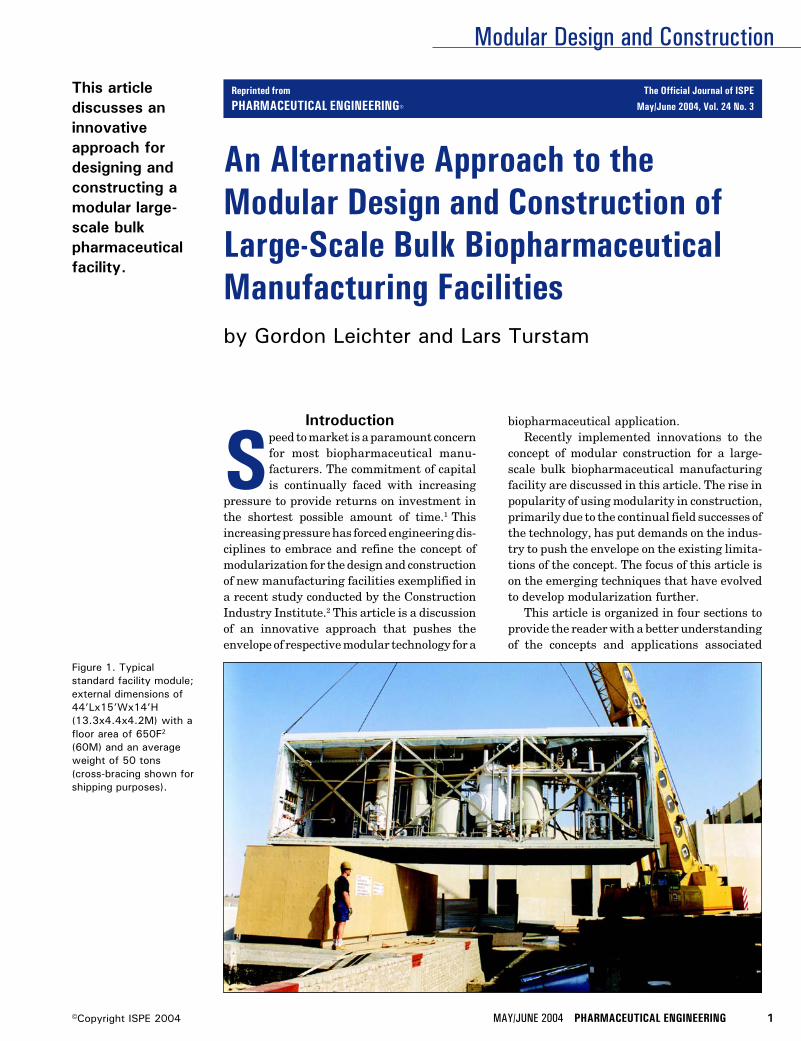
This articlediscusses aninnovativeapproach fordesigning andconstructing amodular large-scale bulkpharmaceuticalfacility.
Introduction
Speed to market is a paramount concernfor most biopharmaceutical manu-facturers. The commitment of capitalis continually faced with increasing
pressure to provide returns on investment inthe shortest possible amount of time.1 Thisincreasing pressure has forced engineering dis-ciplines to embrace and refine the concept ofmodularization for the design and constructionof new manufacturing facilities exemplified ina recent study conducted by the ConstructionIndustry Institute.2 This article is a discussionof an innovative approach that pushes theenvelope of respective modular technology for a
biopharmaceutical application.Recently implemented innovations to the
concept of modular construction for a large-scale bulk biopharmaceutical manufacturingfacility are discussed in this article. The rise inpopularity of using modularity in construction,primarily due to the continual field successes ofthe technology, has put demands on the indus-try to push the envelope on the existing limita-tions of the concept. The focus of this article ison the emerging techniques that have evolvedto develop modularization further.
This article is organized in four sections toprovide the reader with a better understandingof the concepts and applications associated
Figure 1. Typicalstandard facility module;external dimensions of44’Lx15’Wx14’H(13.3x4.4x4.2M) with afloor area of 650F2
(60M) and an averageweight of 50 tons(cross-bracing shown forshipping purposes).
Reprinted from The Official Journal of ISPE
PHARMACEUTICAL ENGINEERING® May/June 2004, Vol. 24 No. 3
Modular Design and Construction
2 PHARMACEUTICAL ENGINEERING MAY/JUNE 2004 ©Copyright ISPE 2004
with modularization. The initial discussion is about modu-larity in general, comparing and contrasting perceptions ofwhat constitutes a module. This discussion leads into aspectsof the benefits and challenges of modular facilities specifi-cally, comparing timelines and cost influences. The thirdsection is a case study of technical innovations recentlyimplemented for a large-scale biopharmaceutical facility,and the conclusion addresses some insights into lessonslearned and forward looking concepts in this developing areaof engineering.
What is Modularization?The term “modular” is used synonymously within the phar-maceutical, biotech, and other industries in reference tomany different applications. Modularity has been used todescribe anything from a software routine within an as-sembled computer program to the fuselage of a Boeing 767®
aircraft. Even as early as 1876, the Statue of Liberty was builtin “modules” before being delivered to New York City.3 There-fore, the concept of modularity is nothing new or innovativein that regard. However, within the pharmaceutical indus-try, the concept of modularization has gained a significantamount of interest. The term “module” has been used todescribe anything from a bank of solenoids to skid mountedprocessing equipment to entire facilities. For the purpose ofthis discussion, the term “modular” and “module” will refer toa self-contained assembly manufactured off-site under con-trolled conditions, then delivered and integrated into thefinal point of use location with the minimal amount of re-assembly.2
Process Modules vs. Facility ModulesProcess equipment mounted within large steel frames orskids constitutes one of the more common descriptions of amodule. This modular approach is an ideal application todefer the fabrication of complex piping and instrumentationto a shop environment where there is close proximity to tools,materials, and expert resources. The extent of the module isnot limited to mechanics. Operational testing of both hard-
ware and software can be conducted within a module. Simi-larly, pre-qualification of the respective systems also can beconducted within the constraints of the module. Pre-qualifi-cation alleviates complexities experienced during field start-ups and allows for timely updates to documentation duringtransport and installation.
In a similar manner, there have been technological ad-vancements in modularity extending past the boundaries ofthe equipment skid to include the entire facility. However,there are many variations to the concept of modular facilities.These variations range from the trailer park type stackableoffices ubiquitous to all construction sites to the more sophis-ticated versions used for pre-fabricated buildings, to thestate-of-the-art versions now being used for pharmaceuticalprocessing facilities. The approach to modular constructionhas recently evolved significantly to the level that entirefacilities can be produced under the same controlled condi-tions as described for equipment skids.
Facility ModularizationThis innovative approach to the modularization of pharma-ceutical production facilities allows for the building structureitself, complete with all architectural finishes and processcomponents, to be fabricated off-site under controlled condi-tions. This approach has been proven to alleviate the logisti-cal complications experienced with conventional construc-tion projects. These structural steel modules come completewith poured concrete floors finished to the most demandingrequirements. Walls are insulated and final finishes areapplied. Heating Ventilation and Air-Conditioning (HVAC),electrical, plant, and clean utilities are permanently in-stalled within the modules. Process equipment is installed inthe module in the final operating location as indicated inFigure 1. All of these functions, normally performed in thefield at various levels within the building, are performed inthe workshop at an easily accessible ground floor level forincreased efficiency and quality.
After all of the internal finishes have been applied in anassembly line environment, the modules are stacked to-gether similar to an enormous Lego® model. With all themodules assembled together, interconnections are completedto allow the facility to become functional while still under theworkshop environment. Functional testing, pre-qualifica-tion, and operator training can be conducted on the modularfacility in parallel to the activities occurring at the construc-tion site.
The modular facility can be accepted by the operatingcompany at the module provider’s facility. After acceptance ofthe facility, the modules are disassembled, protected forshipment, and delivered to the permanent location. Therobust structural steel frame of the modules, which serves asthe actual building structure, offers exceedingly superiorshipping protection compared to traditional crating providedby Original Equipment Manufacturers (OEMs). The equip-ment installed within the module, which is in its finaloperating location, will not require reassembly or extensiveretesting.
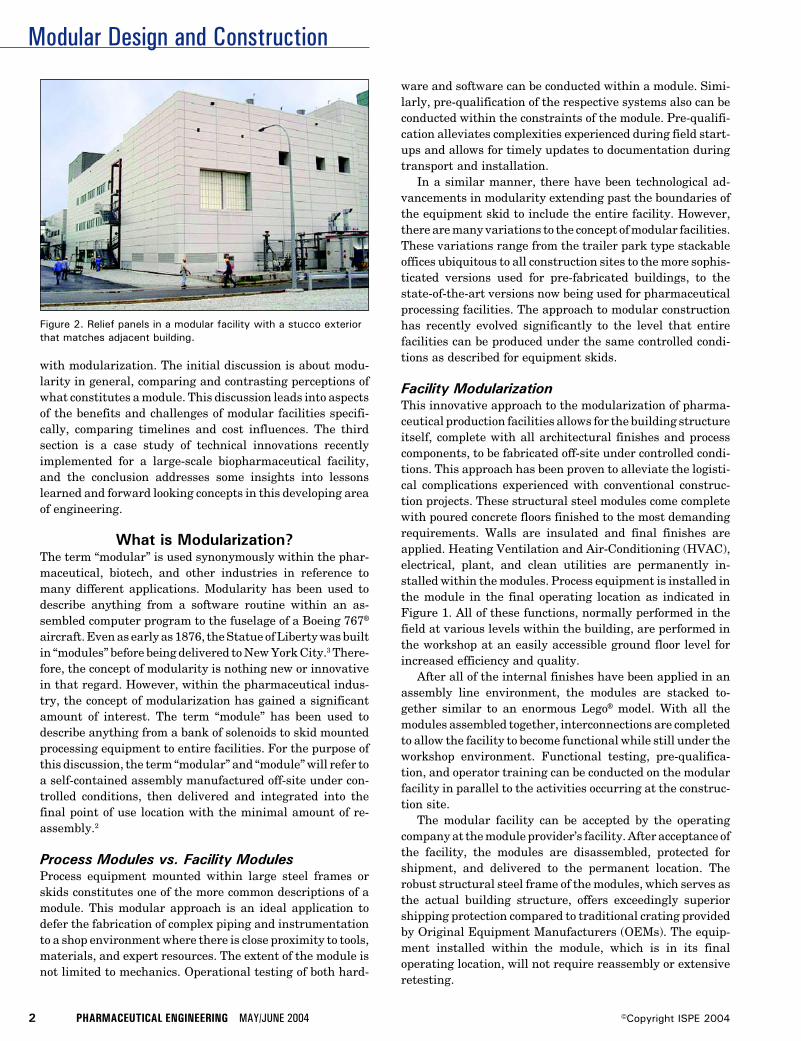
Figure 2. Relief panels in a modular facility with a stucco exteriorthat matches adjacent building.
Modular Design and Construction
MAY/JUNE 2004 PHARMACEUTICAL ENGINEERING 3©Copyright ISPE 2004
The exteriors of the modules are commonly constructedout of epoxy painted steel, insulated to comply with localclimatic conditions and fire ratings. Seismic and hurricanezone requirements are incorporated into the design as re-quired. The robust design of the structural steel frame,usually using 25cm x 12mm (10" x 1/2") square tubularcolumn members, provides a stability to the structure exceed-ing most conventionally built structures. Additionally, anytype of architectural façade can be attached to the exterior,allowing for an external finish that is undistinguishable fromany conventionally constructed building. Special require-
ments for hazardous operations are accommodated by theutilization of relief panels and reinforcement of the adjacentmodule panels as shown in Figure 2.
Benefits and ChallengesThough there are many benefits to the modularization offacilities, it might not be the perfect solution for every project.The following section compares some of the benefits of time tomarket, predictable and reliable results, and high quality tochallenges such as the necessity for a clearly defined scope ofwork [User Requirement Specification (URS)], a commit-
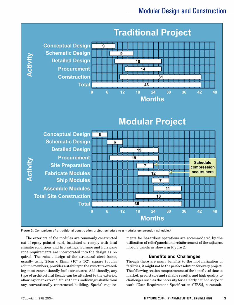
Figure 3. Comparison of a traditional construction project schedule to a modular construction schedule.6
Modular Design and Construction
4 PHARMACEUTICAL ENGINEERING MAY/JUNE 2004 ©Copyright ISPE 2004
ment to long-lead equipment, and an ability to balancechanges in regard to process and schedule.
Improving Time to MarketOne of the main arguments for using modular manufacturingis ultimately in the anticipation of time savings compared toconventional construction and field assembly approaches.Time savings through modular technology on a project is dueto the advantages of parallel activities being conducted offsiteto relieve the congestion and delays that would have occurredif all the required manpower were to converge onsite. Time-liness and enhanced quality, characteristic to modular tech-nology, are realized through shop floor efficiencies undercontrolled conditions.2 These conditions allow for repeatableand consistent results, while eliminating the extraneouseffects of weather delays, worker slow downs, and unpredict-able site logistics.
For the above reasons, modularity has gained recentpopularity as an accepted method for minimizing new facilityconstruction timelines due to the inherent predictability ofthe project process. Parallel activities between site prepara-tion of foundations and non-critical support structures can beperformed while the more sophisticated process intensiveequipment is fabricated off-site. Even though the initial pricefor using modularization may appear to exceed conventionalconstruction, the assurance of a predictable outcome andreduced timeline are clear cost savings incentive for operat-ing companies.2 Net present value of investments combinedwith earlier product revenue is an important consideration inconstruction projects, as larger plants become more capitalintensive.4 The increased demands for earlier return oncapital employed are transcending into increased pressure onengineering disciplines to bring facilities on line faster.5
Time to market is one of the biggest concerns in regard toemployed capital and market opportunities.1 Consideringthat some products are worth millions of dollars a day to theproducing company, every day a facility is not producingproduct is a loss on that capital employed. With the increasein demand for large scale manufacturing, the complexity ofprojects spans across many issues and disciplines. The real-ity of these large-scale projects is that if built conventionally,it would require an extremely large number of skilled labor-ers and material coordination at the jobsite. This jobsitecoordination would result in a significant effort to provideoffice housing, parking, and material receiving and storage.These efforts would be prohibitive from a logistical stand-point alone, while adding more expense and time to theproject. Just the limitations to personnel access due to themaximum allowable density of people per square foot couldmake site construction take twice as long for conventionalconstruction compared to modular construction.2
The advantage of conducting many activities in parallelallows for significant schedule compression in comparison totraditionally built projects - Figure 3.6 Schedule compressionand quality gains are realized through the efficiencies ofmanufacturing under controlled conditions. These gains canbe envisioned through the ease of access for workers to every
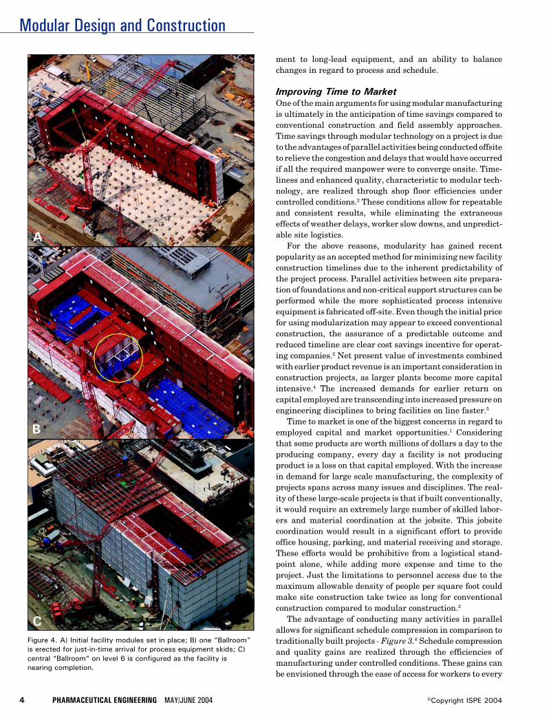
Figure 4. A) Initial facility modules set in place; B) one “Ballroom”is erected for just-in-time arrival for process equipment skids; C)central “Ballroom” on level 6 is configured as the facility isnearing completion.
Modular Design and Construction
MAY/JUNE 2004 PHARMACEUTICAL ENGINEERING 5©Copyright ISPE 2004
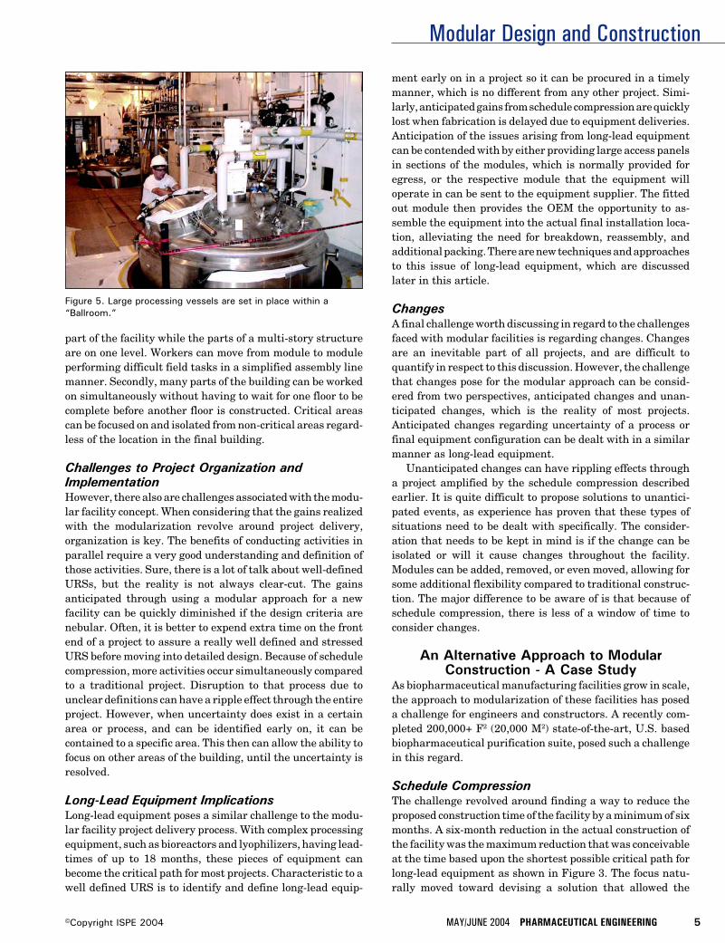
Figure 5. Large processing vessels are set in place within a“Ballroom.”
part of the facility while the parts of a multi-story structureare on one level. Workers can move from module to moduleperforming difficult field tasks in a simplified assembly linemanner. Secondly, many parts of the building can be workedon simultaneously without having to wait for one floor to becomplete before another floor is constructed. Critical areascan be focused on and isolated from non-critical areas regard-less of the location in the final building.
Challenges to Project Organization andImplementationHowever, there also are challenges associated with the modu-lar facility concept. When considering that the gains realizedwith the modularization revolve around project delivery,organization is key. The benefits of conducting activities inparallel require a very good understanding and definition ofthose activities. Sure, there is a lot of talk about well-definedURSs, but the reality is not always clear-cut. The gainsanticipated through using a modular approach for a newfacility can be quickly diminished if the design criteria arenebular. Often, it is better to expend extra time on the frontend of a project to assure a really well defined and stressedURS before moving into detailed design. Because of schedulecompression, more activities occur simultaneously comparedto a traditional project. Disruption to that process due tounclear definitions can have a ripple effect through the entireproject. However, when uncertainty does exist in a certainarea or process, and can be identified early on, it can becontained to a specific area. This then can allow the ability tofocus on other areas of the building, until the uncertainty isresolved.
Long-Lead Equipment ImplicationsLong-lead equipment poses a similar challenge to the modu-lar facility project delivery process. With complex processingequipment, such as bioreactors and lyophilizers, having lead-times of up to 18 months, these pieces of equipment canbecome the critical path for most projects. Characteristic to awell defined URS is to identify and define long-lead equip-
ment early on in a project so it can be procured in a timelymanner, which is no different from any other project. Simi-larly, anticipated gains from schedule compression are quicklylost when fabrication is delayed due to equipment deliveries.Anticipation of the issues arising from long-lead equipmentcan be contended with by either providing large access panelsin sections of the modules, which is normally provided foregress, or the respective module that the equipment willoperate in can be sent to the equipment supplier. The fittedout module then provides the OEM the opportunity to as-semble the equipment into the actual final installation loca-tion, alleviating the need for breakdown, reassembly, andadditional packing. There are new techniques and approachesto this issue of long-lead equipment, which are discussedlater in this article.
ChangesA final challenge worth discussing in regard to the challengesfaced with modular facilities is regarding changes. Changesare an inevitable part of all projects, and are difficult toquantify in respect to this discussion. However, the challengethat changes pose for the modular approach can be consid-ered from two perspectives, anticipated changes and unan-ticipated changes, which is the reality of most projects.Anticipated changes regarding uncertainty of a process orfinal equipment configuration can be dealt with in a similarmanner as long-lead equipment.
Unanticipated changes can have rippling effects througha project amplified by the schedule compression describedearlier. It is quite difficult to propose solutions to unantici-pated events, as experience has proven that these types ofsituations need to be dealt with specifically. The consider-ation that needs to be kept in mind is if the change can beisolated or will it cause changes throughout the facility.Modules can be added, removed, or even moved, allowing forsome additional flexibility compared to traditional construc-tion. The major difference to be aware of is that because ofschedule compression, there is less of a window of time toconsider changes.
An Alternative Approach to ModularConstruction - A Case Study
As biopharmaceutical manufacturing facilities grow in scale,the approach to modularization of these facilities has poseda challenge for engineers and constructors. A recently com-pleted 200,000+ F2 (20,000 M2) state-of-the-art, U.S. basedbiopharmaceutical purification suite, posed such a challengein this regard.
Schedule CompressionThe challenge revolved around finding a way to reduce theproposed construction time of the facility by a minimum of sixmonths. A six-month reduction in the actual construction ofthe facility was the maximum reduction that was conceivableat the time based upon the shortest possible critical path forlong-lead equipment as shown in Figure 3. The focus natu-rally moved toward devising a solution that allowed the
Modular Design and Construction
6 PHARMACEUTICAL ENGINEERING MAY/JUNE 2004 ©Copyright ISPE 2004
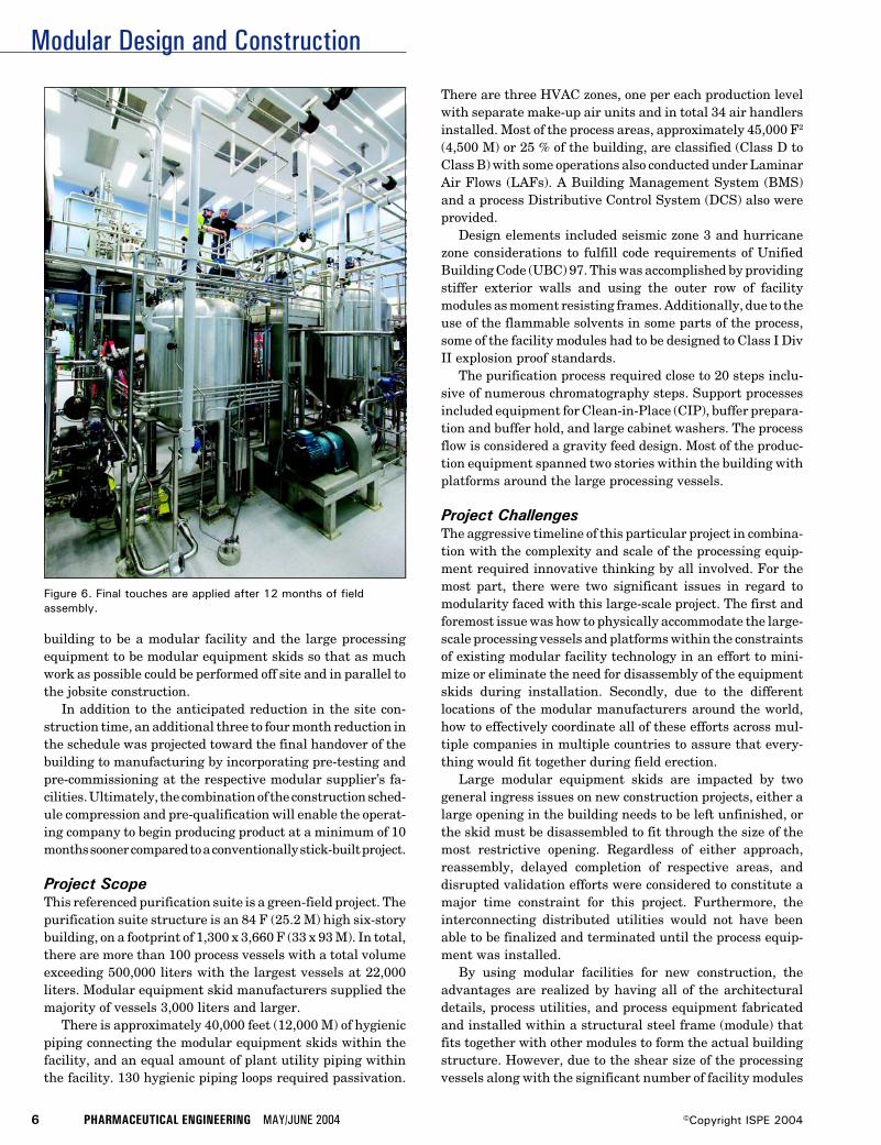
Figure 6. Final touches are applied after 12 months of fieldassembly.
building to be a modular facility and the large processingequipment to be modular equipment skids so that as muchwork as possible could be performed off site and in parallel tothe jobsite construction.
In addition to the anticipated reduction in the site con-struction time, an additional three to four month reduction inthe schedule was projected toward the final handover of thebuilding to manufacturing by incorporating pre-testing andpre-commissioning at the respective modular supplier’s fa-cilities. Ultimately, the combination of the construction sched-ule compression and pre-qualification will enable the operat-ing company to begin producing product at a minimum of 10months sooner compared to a conventionally stick-built project.
Project ScopeThis referenced purification suite is a green-field project. Thepurification suite structure is an 84 F (25.2 M) high six-storybuilding, on a footprint of 1,300 x 3,660 F (33 x 93 M). In total,there are more than 100 process vessels with a total volumeexceeding 500,000 liters with the largest vessels at 22,000liters. Modular equipment skid manufacturers supplied themajority of vessels 3,000 liters and larger.
There is approximately 40,000 feet (12,000 M) of hygienicpiping connecting the modular equipment skids within thefacility, and an equal amount of plant utility piping withinthe facility. 130 hygienic piping loops required passivation.
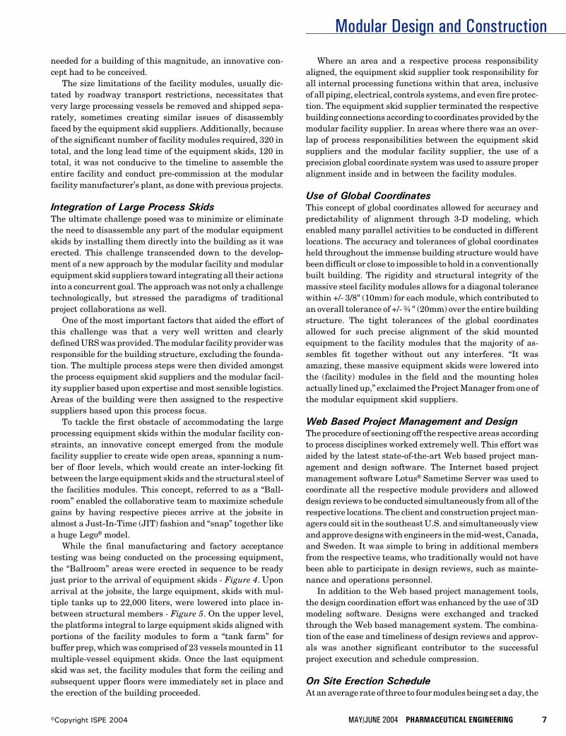
There are three HVAC zones, one per each production levelwith separate make-up air units and in total 34 air handlersinstalled. Most of the process areas, approximately 45,000 F2
(4,500 M) or 25 % of the building, are classified (Class D toClass B) with some operations also conducted under LaminarAir Flows (LAFs). A Building Management System (BMS)and a process Distributive Control System (DCS) also wereprovided.
Design elements included seismic zone 3 and hurricanezone considerations to fulfill code requirements of UnifiedBuilding Code (UBC) 97. This was accomplished by providingstiffer exterior walls and using the outer row of facilitymodules as moment resisting frames. Additionally, due to theuse of the flammable solvents in some parts of the process,some of the facility modules had to be designed to Class I DivII explosion proof standards.
The purification process required close to 20 steps inclu-sive of numerous chromatography steps. Support processesincluded equipment for Clean-in-Place (CIP), buffer prepara-tion and buffer hold, and large cabinet washers. The processflow is considered a gravity feed design. Most of the produc-tion equipment spanned two stories within the building withplatforms around the large processing vessels.
Project ChallengesThe aggressive timeline of this particular project in combina-tion with the complexity and scale of the processing equip-ment required innovative thinking by all involved. For themost part, there were two significant issues in regard tomodularity faced with this large-scale project. The first andforemost issue was how to physically accommodate the large-scale processing vessels and platforms within the constraintsof existing modular facility technology in an effort to mini-mize or eliminate the need for disassembly of the equipmentskids during installation. Secondly, due to the differentlocations of the modular manufacturers around the world,how to effectively coordinate all of these efforts across mul-tiple companies in multiple countries to assure that every-thing would fit together during field erection.
Large modular equipment skids are impacted by twogeneral ingress issues on new construction projects, either alarge opening in the building needs to be left unfinished, orthe skid must be disassembled to fit through the size of themost restrictive opening. Regardless of either approach,reassembly, delayed completion of respective areas, anddisrupted validation efforts were considered to constitute amajor time constraint for this project. Furthermore, theinterconnecting distributed utilities would not have beenable to be finalized and terminated until the process equip-ment was installed.
By using modular facilities for new construction, theadvantages are realized by having all of the architecturaldetails, process utilities, and process equipment fabricatedand installed within a structural steel frame (module) thatfits together with other modules to form the actual buildingstructure. However, due to the shear size of the processingvessels along with the significant number of facility modules
Modular Design and Construction
MAY/JUNE 2004 PHARMACEUTICAL ENGINEERING 7©Copyright ISPE 2004
needed for a building of this magnitude, an innovative con-cept had to be conceived.
The size limitations of the facility modules, usually dic-tated by roadway transport restrictions, necessitates thatvery large processing vessels be removed and shipped sepa-rately, sometimes creating similar issues of disassemblyfaced by the equipment skid suppliers. Additionally, becauseof the significant number of facility modules required, 320 intotal, and the long lead time of the equipment skids, 120 intotal, it was not conducive to the timeline to assemble theentire facility and conduct pre-commission at the modularfacility manufacturer’s plant, as done with previous projects.
Integration of Large Process SkidsThe ultimate challenge posed was to minimize or eliminatethe need to disassemble any part of the modular equipmentskids by installing them directly into the building as it waserected. This challenge transcended down to the develop-ment of a new approach by the modular facility and modularequipment skid suppliers toward integrating all their actionsinto a concurrent goal. The approach was not only a challengetechnologically, but stressed the paradigms of traditionalproject collaborations as well.
One of the most important factors that aided the effort ofthis challenge was that a very well written and clearlydefined URS was provided. The modular facility provider wasresponsible for the building structure, excluding the founda-tion. The multiple process steps were then divided amongstthe process equipment skid suppliers and the modular facil-ity supplier based upon expertise and most sensible logistics.Areas of the building were then assigned to the respectivesuppliers based upon this process focus.
To tackle the first obstacle of accommodating the largeprocessing equipment skids within the modular facility con-straints, an innovative concept emerged from the modulefacility supplier to create wide open areas, spanning a num-ber of floor levels, which would create an inter-locking fitbetween the large equipment skids and the structural steel ofthe facilities modules. This concept, referred to as a “Ball-room” enabled the collaborative team to maximize schedulegains by having respective pieces arrive at the jobsite inalmost a Just-In-Time (JIT) fashion and “snap” together likea huge Lego® model.
While the final manufacturing and factory acceptancetesting was being conducted on the processing equipment,the “Ballroom” areas were erected in sequence to be readyjust prior to the arrival of equipment skids - Figure 4. Uponarrival at the jobsite, the large equipment, skids with mul-tiple tanks up to 22,000 liters, were lowered into place in-between structural members - Figure 5. On the upper level,the platforms integral to large equipment skids aligned withportions of the facility modules to form a “tank farm” forbuffer prep, which was comprised of 23 vessels mounted in 11multiple-vessel equipment skids. Once the last equipmentskid was set, the facility modules that form the ceiling andsubsequent upper floors were immediately set in place andthe erection of the building proceeded.
Where an area and a respective process responsibilityaligned, the equipment skid supplier took responsibility forall internal processing functions within that area, inclusiveof all piping, electrical, controls systems, and even fire protec-tion. The equipment skid supplier terminated the respectivebuilding connections according to coordinates provided by themodular facility supplier. In areas where there was an over-lap of process responsibilities between the equipment skidsuppliers and the modular facility supplier, the use of aprecision global coordinate system was used to assure properalignment inside and in between the facility modules.
Use of Global CoordinatesThis concept of global coordinates allowed for accuracy andpredictability of alignment through 3-D modeling, whichenabled many parallel activities to be conducted in differentlocations. The accuracy and tolerances of global coordinatesheld throughout the immense building structure would havebeen difficult or close to impossible to hold in a conventionallybuilt building. The rigidity and structural integrity of themassive steel facility modules allows for a diagonal tolerancewithin +/- 3/8" (10mm) for each module, which contributed toan overall tolerance of +/- ¾ " (20mm) over the entire buildingstructure. The tight tolerances of the global coordinatesallowed for such precise alignment of the skid mountedequipment to the facility modules that the majority of as-sembles fit together without out any interferes. “It wasamazing, these massive equipment skids were lowered intothe (facility) modules in the field and the mounting holesactually lined up,” exclaimed the Project Manager from one ofthe modular equipment skid suppliers.
Web Based Project Management and DesignThe procedure of sectioning off the respective areas accordingto process disciplines worked extremely well. This effort wasaided by the latest state-of-the-art Web based project man-agement and design software. The Internet based projectmanagement software Lotus® Sametime Server was used tocoordinate all the respective module providers and alloweddesign reviews to be conducted simultaneously from all of therespective locations. The client and construction project man-agers could sit in the southeast U.S. and simultaneously viewand approve designs with engineers in the mid-west, Canada,and Sweden. It was simple to bring in additional membersfrom the respective teams, who traditionally would not havebeen able to participate in design reviews, such as mainte-nance and operations personnel.
In addition to the Web based project management tools,the design coordination effort was enhanced by the use of 3Dmodeling software. Designs were exchanged and trackedthrough the Web based management system. The combina-tion of the ease and timeliness of design reviews and approv-als was another significant contributor to the successfulproject execution and schedule compression.
On Site Erection ScheduleAt an average rate of three to four modules being set a day, the
Modular Design and Construction
8 PHARMACEUTICAL ENGINEERING MAY/JUNE 2004 ©Copyright ISPE 2004
entire building was erected in less than eight months. Thisunprecedented accomplishment began with site constructionstarting in mid 2002. The first modules arrived at site inJanuary of 2003, and began to be set in place in February -Figure 4. The last facility module was set in place in mid-September of 2003. Interconnections, elevators, and a rawmaterial penthouse were completed over the following fivemonths with a handover to the operating company by the endof March 2004. “The total site construction of this buildingwould have taken close to 36 months if built conventionally,”commented the Construction Site Manager.
Lessons Learned and a Look ForwardThe large-scale biopharmaceutical project discussed abovewill be well into the commissioning phase by the time thisarticle is published - Figure 6. For the purpose of clientconfidentiality and process propriety, names and detailshave been excluded. Though technological strides in regard tothe advancements in modular concepts were achieved on thisproject, there are three lessons that can be shared as a benefitto the industry for future projects of similar scale. Theselessons revolve around; first, a true understanding of whatshould or shouldn’t be completed prior to site work as well aswhat can and cannot be done with modular technology;second, a weakest link situation in regard to all suppliers onthe project; and third, the excellent example of coordinationefforts for all the logistics.
When considering using modular technology, redundancyof efforts in comparison to return on investment needs to beconsidered at the initial planning stage of the project. Thereare redundant efforts such as pre-testing and pre-commis-sioning of equipment, process loops, HVAC loops, etc.; thatwill assure a higher rate of return with the avoidance ofsurprises and unplanned delays during start-up. Conversely,there are efforts to consider such as passivation and exten-sive disassembly of equipment, where there is little advan-tage due to the necessity to repeat the process in the fieldanyway.
Additionally, as much mechanical and electrical work aspossible should be carried out under the controlled conditionsof the modular supplier’s shop environment. However, it wasfelt that the size of this facility made it necessary to conductmost of the electrical cabling work and HVAC ductwork at theconstruction site. Specifically, some of the ceiling fixtures,ductwork, and electrical cabling were left to be finished in thefield to get the facility modules on site as soon as possible. Dueto the accelerated pace of the compressed JIT schedule at theconstruction site, the unpredictability of deferred field laborcaused complications. In hindsight, it would have been betterto hold those respective facility modules back in the workshopfor some additional time, which turned out to be more thandouble in the field.
From a weakest link standpoint, where modularizationallows for many things to happen in parallel, schedule com-pression gains can be compromised if critical activities do not
happen succinctly. While some delays can be overcome due tothe inherent flexibility of being able to juggle some materialand equipment delays by working sections of the facilityindependent of other respective areas, pre-planning andcoordination efforts leave little room for mishaps. Extra effortneeds to be expended to assure sub-suppliers keep on track,drawings are approved in a timely manner, and utilities areavailable when needed.
Due to the speed and number of activities occurring simul-taneously, delays in a compressed schedule are amplifiedwhen things can no longer be worked around. This situationrelates to internal and external issues to the project. In thecase of the large-scale biopharmaceutical facility, intensefocus was given to internal aspects of the purification suite,when it was discovered that the plant utilities, which wereconventionally stick built, were behind schedule. Schedulegains could be jeopardized if these utilities are not availablein a timely manner.
Future TrendsIn conclusion, modularization has evolved over the years asmore and more pressure has been put on engineering disci-plines to provide innovative ways to provide better returns oncapital employed. The efforts that go into modularizationneed to be considered from a project delivery standpoint inthe initial planning phases of a project to maximize thepotential for greater returns. Increased efficiencies will berealized as the industry learns more about how to better usethe benefits and understand challenges of this emergingtechnology.
Future developments in this technology will focus more onthe point of origin for pre-manufacturing in an effort toperform as much work and pre-qualification as possibleoffsite. Increased acceptance of the concept will be evidencedin preparing facility modules and delivering them to OEMswhere long-lead equipment can be installed directly into themodules and shipped directly to the final location, alleviatingas many interim steps as possible.
Additional foresight into the pre-testing of DCS and Su-pervisory Control and Data Acquisition (SCADA) systemswithin the modules while in the workshop will bring addedbenefits to the sometimes unpredictable and hectic start-upissues that plague startups of conventionally built projects.Biopharmaceutical facilities will no longer be thought of asfixed assets because the entire facility will be able to berelocated similar to a piece of equipment. There also will bemore modularization of other parts of the facility such asutility packages. These trends indicate that modularizationis becoming more mainstream and will provide for increasinginnovation in the field of facility design and construction.
References1. Arndt, M., “Pharmaceuticals: For Drugmakers, There’s
No Panacea,” BusinessWeek Online; January 12, 2004.
Modular Design and Construction
MAY/JUNE 2004 PHARMACEUTICAL ENGINEERING 9©Copyright ISPE 2004
2. Construction Industry Institute; (2002); Prefabrication,Preassembly, Modularization, and Offsite Fabrica-tion in Industrial Construction: A Framework forDecision-Making; The University of Texas at Austin;Research Summary 171-1, p.7, 10.
3. Levine, B. and Story, I. F., Statue of Liberty NationalMonument Bedloe’s Island, New York, National ParkService, Historical Handbook Series No. 11Washington, D.C., 1954.
4. Maravelias, C. T., and Grossmann, Ignacio E., “Simulta-neous Planning for New Product Development and Designof Manufacturing Facilities,” Department of ChemicalEngineering, Carnegie Mellon University, Pittsburgh,PA, 2001.
5. U.S. Congress, Office of Technology Assessment, Phar-maceutical R&D: Costs, Risks and Rewards, OTA-H-522, Washington, DC: U.S. Government Printing. Office,February 1993.
6. Rudolph, J., and Turstam, L., “An Alternative Approach inOrder to Meet Short Implementation Schedule for LargeBiotechnology Projects,” presented at the ISPE AnnualMeeting, November 2003.
About the AuthorsGordon Leichter is currently the Directorof Business Development, Pharmadule, Inc.He has more than 20 years of experienceworking in the pharmaceutical industry withequipment suppliers. He has extensive expe-rience with manufacturing, design and engi-neering of sterilization systems. Some of hispreviously held positions were director of
marketing for Getinge and product manager for AMSCO/Finn-Aqua (now Steris Corp). He holds a MS in management.He can be contacted by tel: 1-908/470-1023 or by email:[email protected].
Pharmadule, Inc., 500 Hills Dr., Bedminster, NJ 07921.
Lars Turstam is currently a Senior ProjectManager for Pharmadule in Stockholm, Swe-den. He joined Pharmadule in 1997 as atechnical director. From companies withinthe Pharmacia Corp. (now Pfizer), Turstamhas gained more than 30 years of experiencefrom the pharmaceutical business, from R&Dfor 12 years, from production management
for eight years, and from engineering, project management,and global investments for another 12 years. That last periodincluded a three-year stay in China as project and productionmanager for a Greenfield Manufacturing Plant Project. Inboth companies, Turstam has worked with site develop-ments, feasibility studies, project designs, and management.
Pharmadule, 28 Danvik Center, Nacka, Sweden.
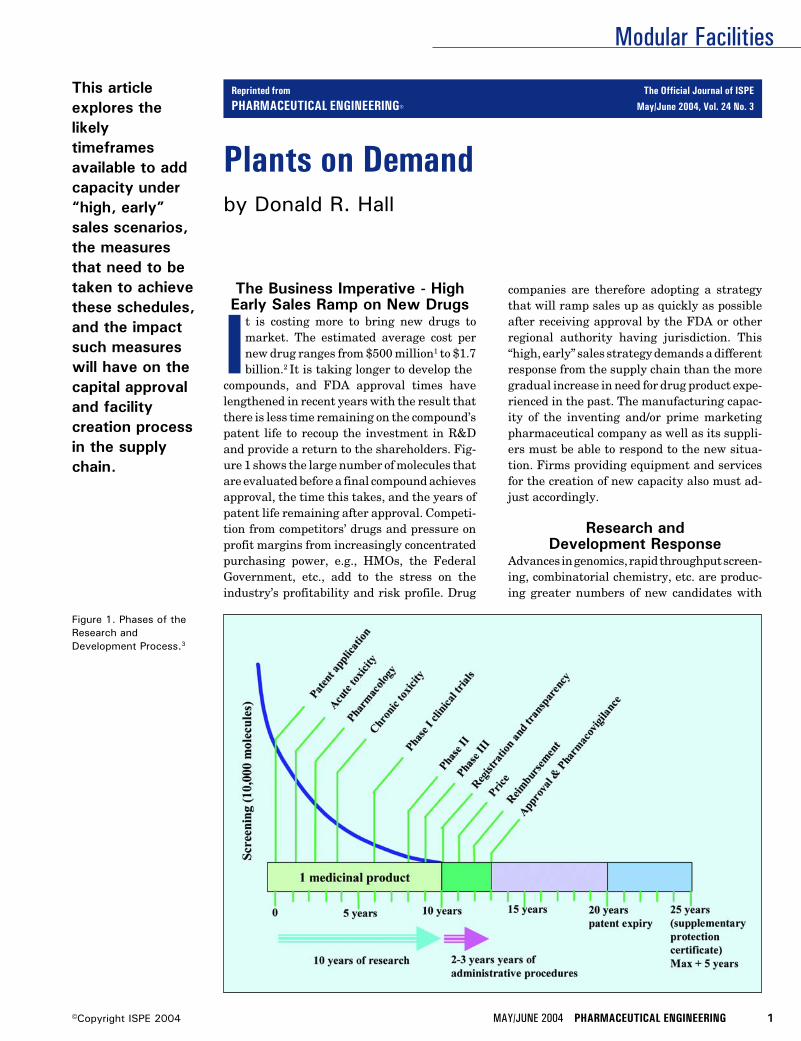
Modular Facilities
MAY/JUNE 2004 PHARMACEUTICAL ENGINEERING 1©Copyright ISPE 2004
Plants on Demandby Donald R. Hall
This articleexplores thelikelytimeframesavailable to addcapacity under“high, early”sales scenarios,the measuresthat need to betaken to achievethese schedules,and the impactsuch measureswill have on thecapital approvaland facilitycreation processin the supplychain.
Figure 1. Phases of theResearch andDevelopment Process.3
The Business Imperative - HighEarly Sales Ramp on New Drugs
It is costing more to bring new drugs tomarket. The estimated average cost pernew drug ranges from $500 million1 to $1.7billion.2 It is taking longer to develop the
compounds, and FDA approval times havelengthened in recent years with the result thatthere is less time remaining on the compound’spatent life to recoup the investment in R&Dand provide a return to the shareholders. Fig-ure 1 shows the large number of molecules thatare evaluated before a final compound achievesapproval, the time this takes, and the years ofpatent life remaining after approval. Competi-tion from competitors’ drugs and pressure onprofit margins from increasingly concentratedpurchasing power, e.g., HMOs, the FederalGovernment, etc., add to the stress on theindustry’s profitability and risk profile. Drug
companies are therefore adopting a strategythat will ramp sales up as quickly as possibleafter receiving approval by the FDA or otherregional authority having jurisdiction. This“high, early” sales strategy demands a differentresponse from the supply chain than the moregradual increase in need for drug product expe-rienced in the past. The manufacturing capac-ity of the inventing and/or prime marketingpharmaceutical company as well as its suppli-ers must be able to respond to the new situa-tion. Firms providing equipment and servicesfor the creation of new capacity also must ad-just accordingly.
Research andDevelopment Response
Advances in genomics, rapid throughput screen-ing, combinatorial chemistry, etc. are produc-ing greater numbers of new candidates with
Reprinted from The Official Journal of ISPE
PHARMACEUTICAL ENGINEERING® May/June 2004, Vol. 24 No. 3
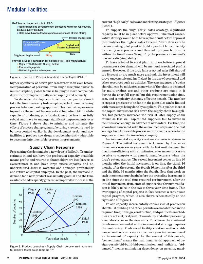
Modular Facilities
2 PHARMACEUTICAL ENGINEERING MAY/JUNE 2004 ©Copyright ISPE 2004
Figure 3. Product Launches - Supply Chain. Accelerated launchesto achieve faster sales ramp-up.3,8,9
higher specificity of action per researcher than ever before.Reorganization of personnel from single discipline “silos” tomulti-discipline, global teams is helping to move compoundsdown the development path more rapidly and securely.
To decrease development timelines, companies cannottake the time necessary to develop the perfect manufacturingprocess before requesting approval. This means the processesto produce the Active Pharmaceutical Ingredient (API), whilecapable of producing pure product, may be less than fullyrobust and have to undergo significant improvements overtime. Figure 2 shows that to minimize and mitigate theeffects of process changes, manufacturing viewpoints need tobe incorporated earlier in the development cycle, and newfacilities to produce new drugs must be inherently adaptableto accommodate inevitable process improvements.
Supply Chain ResponseForecasting the demand for a new drug is difficult. To under-estimate it and not have the production capacity availablemeans profits and returns to shareholders are lost forever; tooverestimate it and have large excess capacity and anunderutilized asset is wasteful and damages profitabilityand return on capital employed. In the past, the increase indemand for a new product was usually gradual and the timeavailable to add capacity generous compared to the case of the
current “high early” sales and marketing strategies - Figures3 and 4.
To support the “high early” sales strategy, significantcapacity must be in place before approval. The most conser-vative strategy would be to have a plant built before approvalthat matches the highest sales forecast. Alternatives are touse an existing pilot plant or build a product launch facilityfor use by new products and then add purpose built unitswithin the timeframes “bought” by the previous increment’smarket satisfying ability.
To have a top of forecast plant in place before approvalguarantees sales demand will be met and associated profitsearned. However, if the drug fails or actual sales fall short oftop forecast or are much more gradual, the investment willprove uneconomic and inefficient in the use of personnel andother resources such as utilities. The consequences of such ashortfall can be mitigated somewhat if the plant is designedfor multi-product use and other products are made in itduring the shortfall period, but this requirement adds time,cost, and complexity that may offset its benefit. The numberof steps or processes to be done in the plant also can be limitedwith more steps being done by suppliers. This pushes more ofthe capital investment risk down the supply chain to suppli-ers, but perhaps increases the risk of later supply chainfailure as less well capitalized suppliers fail to invest infacilities soon enough in advance of new orders. Further, theknow-how associated with the outsourced steps and the costsavings from foreseeable process improvements accrue to thesupplier and not the inventing company.
An incremental capacity creation scenario is shown inFigure 5. The initial increment is followed by four moreincrements over seven years with the last unit designed formaximum efficiency with an optimized or even new process tobe able to compete with generic manufacturers when thedrug’s patent expires. The second increment comes on line 20months after the initial increment is on line, the third, 16months after the second, the fourth 16 months after the thirdand the fifth, 36 months after the fourth. Note that work oneach increment must begin before the preceding increment ison line since the total time required per increment, after theinitial increment, from start of engineering through valida-tion is likely to be in the two to three year time frame. Thisoverlapping of capital projects in fact becomes a continuouscapital program, which is also shown schematically on theright side of Figure 4.
To add capacity incrementally carries risk of productionshortfall if building and other permits are not obtained in therequired time; if design, construction, and qualification sched-ules are not met; or if product variability and other processinganomalies occur in the new units. To achieve the shortenedtimeframes demanded of the incremental strategy requiresthe embracing of advanced facility creation methods. Ad-vanced methods can save as much as a year in the creation ofan increment of capacity. In the context of this article,“conventional” means the traditional serial approach of de-sign-permit-bid-build-bid-commission and validate. “Ad-vanced,” means minimizing dependency on permits, maxi-
Figure 2. The use of Process Analytical Technologies (PAT).3
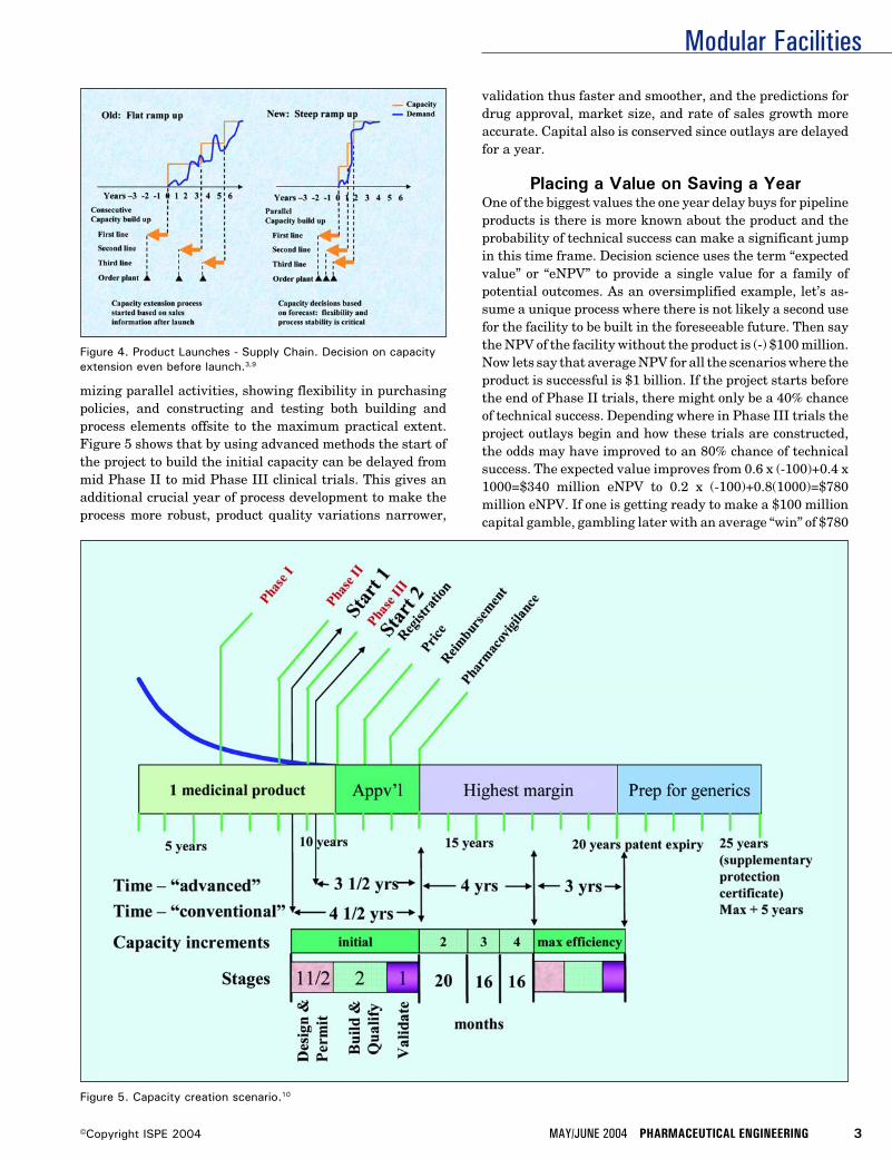
Modular Facilities
MAY/JUNE 2004 PHARMACEUTICAL ENGINEERING 3©Copyright ISPE 2004
mizing parallel activities, showing flexibility in purchasingpolicies, and constructing and testing both building andprocess elements offsite to the maximum practical extent.Figure 5 shows that by using advanced methods the start ofthe project to build the initial capacity can be delayed frommid Phase II to mid Phase III clinical trials. This gives anadditional crucial year of process development to make theprocess more robust, product quality variations narrower,
validation thus faster and smoother, and the predictions fordrug approval, market size, and rate of sales growth moreaccurate. Capital also is conserved since outlays are delayedfor a year.
Placing a Value on Saving a YearOne of the biggest values the one year delay buys for pipelineproducts is there is more known about the product and theprobability of technical success can make a significant jumpin this time frame. Decision science uses the term “expectedvalue” or “eNPV” to provide a single value for a family ofpotential outcomes. As an oversimplified example, let’s as-sume a unique process where there is not likely a second usefor the facility to be built in the foreseeable future. Then saythe NPV of the facility without the product is (-) $100 million.Now lets say that average NPV for all the scenarios where theproduct is successful is $1 billion. If the project starts beforethe end of Phase II trials, there might only be a 40% chanceof technical success. Depending where in Phase III trials theproject outlays begin and how these trials are constructed,the odds may have improved to an 80% chance of technicalsuccess. The expected value improves from 0.6 x (-100)+0.4 x1000=$340 million eNPV to 0.2 x (-100)+0.8(1000)=$780million eNPV. If one is getting ready to make a $100 millioncapital gamble, gambling later with an average “win” of $780
Figure 4. Product Launches - Supply Chain. Decision on capacityextension even before launch.3,9
Figure 5. Capacity creation scenario.10
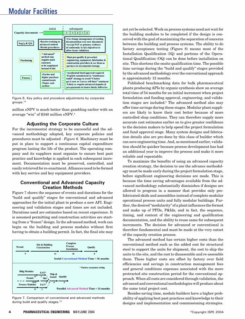
Modular Facilities
4 PHARMACEUTICAL ENGINEERING MAY/JUNE 2004 ©Copyright ISPE 2004
Figure 7. Comparison of conventional and advanced methodsduring build and qualify stages.10
million eNPV is much better than gambling earlier with anaverage “win” of $340 million eNPV.4
Adjusting the Corporate CultureFor the incremental strategy to be successful and the ad-vanced methodology adopted, key corporate policies andprocedures must be adjusted - Figure 6. Machinery must beput in place to support a continuous capital expenditureprogram lasting the life of the product. The operating com-pany and its suppliers must organize to ensure best pastpractice and knowledge is applied in each subsequent incre-ment. Documentation must be preserved, controlled, andeasily retrieved for re-enactment. Alliances need to be formedwith key service and key equipment providers.
Conventional and Advanced CapacityCreation Methods
Figure 7 shows the sequence of events and durations for the“build and qualify” stages for conventional and advancedapproaches for the initial plant to produce a new API. Engi-neering and validation stages and times are not included.Durations used are estimates based on recent experience. Itis assumed permitting and construction activities are start-ing from a “frozen” design. In the advanced method, work canbegin on the building and process modules without firsthaving to obtain a building permit. In fact, the final site may
Figure 6. Key policy and procedure adjustments by corporategroups.10
not yet be selected. Work on process systems need not wait forthe building modules to be completed if the design is con-ceived with the goal of maximizing the separation of concernsbetween the building and process systems. The ability to dofactory acceptance testing (Figure 8) means most of theInstallation Qualification (IQ) and portions of the Opera-tional Qualification (OQ) can be done before installation onsite. This shortens the onsite qualification time. The possibletime savings during the “build and qualify” stages providedby the advanced methodology over the conventional approachis approximately 12 months.
Published benchmarking data for bulk pharmaceuticalplants producing APIs by organic synthesis show an averagetotal time of 54 months for an initial increment when projectformulation and funding approval, engineering, and valida-tion stages are included.5 The advanced method also mayoffer time savings during these stages. Modular plant suppli-ers are likely to know their cost better because of morecontrolled shop conditions. They can therefore supply moreaccurate cost estimates earlier on to give greater confidenceto the decision makers to help speed the project formulationand fund approval stage. Many system designs and fabrica-tion details also are pre-done by this class of builder whichcan save engineering time. And, as mentioned earlier, valida-tion should be quicker because process development has hadan additional year to improve the process and make it morereliable and repeatable.
To maximize the benefits of using an advanced capacitycreation strategy, the decision to use the advance methodol-ogy must be made early during the project formulation stage,before significant engineering decisions are made. This isbecause the time saving advantages available from the ad-vanced methodology substantially diminishes if designs areallowed to progress in a manner that provides only pre-fabricated skids and assemblies instead of complete modularoperational process units and fully modular buildings. Fur-ther, the desired “modularity” of a plant influences the formatand make up of PFDs, P&Ids, and in fact, the sequence,timing, and content of the engineering and qualificationdocumentation, and the ability to reuse same for subsequentincrements. The decision for advanced or conventional istherefore fundamental and must be made at the very outsetof the capacity creation process.
The advanced method has certain higher costs than theconventional method such as the added cost for structuralsteel to support the units for shipment, the cost to ship theunits to the site, and the cost to disassemble and re-assemblethem. These higher costs are offset by factory over fieldefficiencies and savings in construction management feesand general conditions expenses associated with the moreprotracted site construction period for the conventional ap-proach. When all costs are considered through validation, theadvanced and conventional methodologies will produce aboutthe same total project cost.
Besides saving time, module builders have a higher prob-ability of applying best past practices and knowledge to theirdesigns and implementation and commissioning strategies.
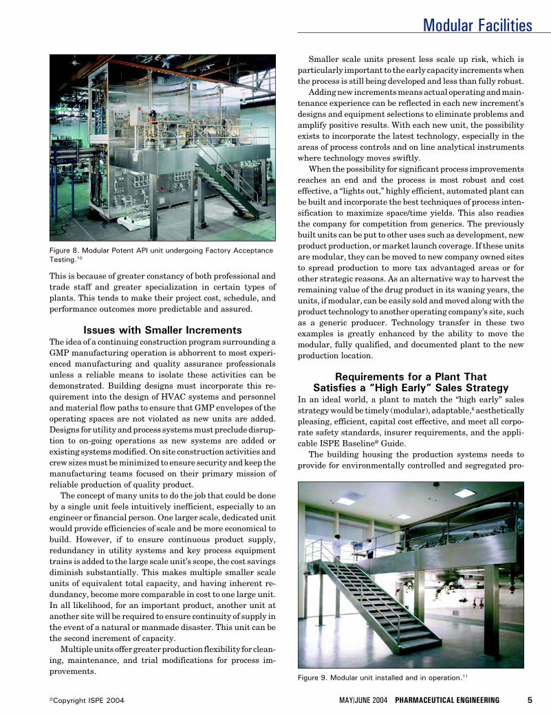
Modular Facilities
MAY/JUNE 2004 PHARMACEUTICAL ENGINEERING 5©Copyright ISPE 2004
This is because of greater constancy of both professional andtrade staff and greater specialization in certain types ofplants. This tends to make their project cost, schedule, andperformance outcomes more predictable and assured.
Issues with Smaller IncrementsThe idea of a continuing construction program surrounding aGMP manufacturing operation is abhorrent to most experi-enced manufacturing and quality assurance professionalsunless a reliable means to isolate these activities can bedemonstrated. Building designs must incorporate this re-quirement into the design of HVAC systems and personneland material flow paths to ensure that GMP envelopes of theoperating spaces are not violated as new units are added.Designs for utility and process systems must preclude disrup-tion to on-going operations as new systems are added orexisting systems modified. On site construction activities andcrew sizes must be minimized to ensure security and keep themanufacturing teams focused on their primary mission ofreliable production of quality product.
The concept of many units to do the job that could be doneby a single unit feels intuitively inefficient, especially to anengineer or financial person. One larger scale, dedicated unitwould provide efficiencies of scale and be more economical tobuild. However, if to ensure continuous product supply,redundancy in utility systems and key process equipmenttrains is added to the large scale unit’s scope, the cost savingsdiminish substantially. This makes multiple smaller scaleunits of equivalent total capacity, and having inherent re-dundancy, become more comparable in cost to one large unit.In all likelihood, for an important product, another unit atanother site will be required to ensure continuity of supply inthe event of a natural or manmade disaster. This unit can bethe second increment of capacity.
Multiple units offer greater production flexibility for clean-ing, maintenance, and trial modifications for process im-provements.
Smaller scale units present less scale up risk, which isparticularly important to the early capacity increments whenthe process is still being developed and less than fully robust.
Adding new increments means actual operating and main-tenance experience can be reflected in each new increment’sdesigns and equipment selections to eliminate problems andamplify positive results. With each new unit, the possibilityexists to incorporate the latest technology, especially in theareas of process controls and on line analytical instrumentswhere technology moves swiftly.
When the possibility for significant process improvementsreaches an end and the process is most robust and costeffective, a “lights out,” highly efficient, automated plant canbe built and incorporate the best techniques of process inten-sification to maximize space/time yields. This also readiesthe company for competition from generics. The previouslybuilt units can be put to other uses such as development, newproduct production, or market launch coverage. If these unitsare modular, they can be moved to new company owned sitesto spread production to more tax advantaged areas or forother strategic reasons. As an alternative way to harvest theremaining value of the drug product in its waning years, theunits, if modular, can be easily sold and moved along with theproduct technology to another operating company’s site, suchas a generic producer. Technology transfer in these twoexamples is greatly enhanced by the ability to move themodular, fully qualified, and documented plant to the newproduction location.
Requirements for a Plant ThatSatisfies a “High Early” Sales Strategy
In an ideal world, a plant to match the “high early” salesstrategy would be timely (modular), adaptable,6 aestheticallypleasing, efficient, capital cost effective, and meet all corpo-rate safety standards, insurer requirements, and the appli-cable ISPE Baseline® Guide.
The building housing the production systems needs toprovide for environmentally controlled and segregated pro-
Figure 8. Modular Potent API unit undergoing Factory AcceptanceTesting.10
Figure 9. Modular unit installed and in operation.11
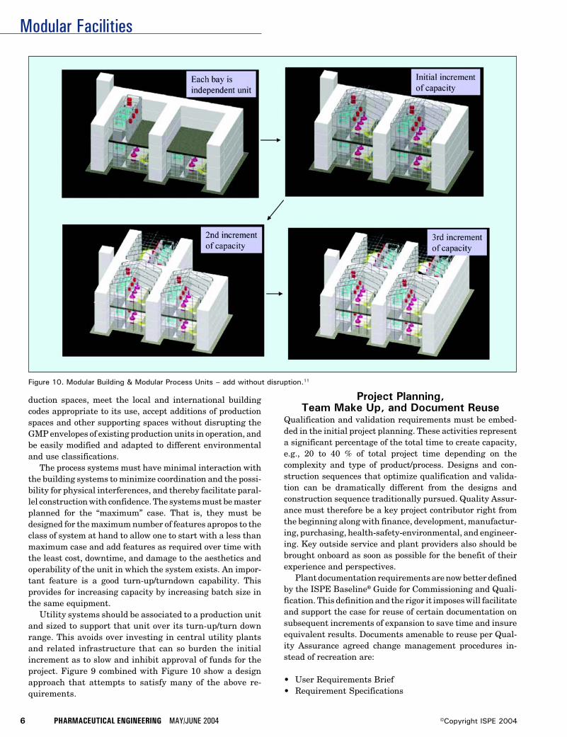
Modular Facilities
6 PHARMACEUTICAL ENGINEERING MAY/JUNE 2004 ©Copyright ISPE 2004
Figure 10. Modular Building & Modular Process Units – add without disruption.11
duction spaces, meet the local and international buildingcodes appropriate to its use, accept additions of productionspaces and other supporting spaces without disrupting theGMP envelopes of existing production units in operation, andbe easily modified and adapted to different environmentaland use classifications.
The process systems must have minimal interaction withthe building systems to minimize coordination and the possi-bility for physical interferences, and thereby facilitate paral-lel construction with confidence. The systems must be masterplanned for the “maximum” case. That is, they must bedesigned for the maximum number of features apropos to theclass of system at hand to allow one to start with a less thanmaximum case and add features as required over time withthe least cost, downtime, and damage to the aesthetics andoperability of the unit in which the system exists. An impor-tant feature is a good turn-up/turndown capability. Thisprovides for increasing capacity by increasing batch size inthe same equipment.
Utility systems should be associated to a production unitand sized to support that unit over its turn-up/turn downrange. This avoids over investing in central utility plantsand related infrastructure that can so burden the initialincrement as to slow and inhibit approval of funds for theproject. Figure 9 combined with Figure 10 show a designapproach that attempts to satisfy many of the above re-quirements.
Project Planning,Team Make Up, and Document Reuse
Qualification and validation requirements must be embed-ded in the initial project planning. These activities representa significant percentage of the total time to create capacity,e.g., 20 to 40 % of total project time depending on thecomplexity and type of product/process. Designs and con-struction sequences that optimize qualification and valida-tion can be dramatically different from the designs andconstruction sequence traditionally pursued. Quality Assur-ance must therefore be a key project contributor right fromthe beginning along with finance, development, manufactur-ing, purchasing, health-safety-environmental, and engineer-ing. Key outside service and plant providers also should bebrought onboard as soon as possible for the benefit of theirexperience and perspectives.
Plant documentation requirements are now better definedby the ISPE Baseline® Guide for Commissioning and Quali-fication. This definition and the rigor it imposes will facilitateand support the case for reuse of certain documentation onsubsequent increments of expansion to save time and insureequivalent results. Documents amenable to reuse per Qual-ity Assurance agreed change management procedures in-stead of recreation are:
• User Requirements Brief• Requirement Specifications
Modular Facilities
MAY/JUNE 2004 PHARMACEUTICAL ENGINEERING 7©Copyright ISPE 2004
• Functional Design Specifications• Validation Master Plan• Detailed Design Specifications• P&IDs• Major Equipment Specs• Equipment Layouts• Site and Building Designs• Environmental and Building Permit Documents• Commissioning Plan• Control Estimate• Building Shop Drawings• Specialty Item Drawings• Mechanical Catalogs• As Built Drawings• Commissioning and Validation protocols• Spare Parts List• Training Materials• SOPs• PAT Data Reports
ConclusionsSpeed in capacity creation is a competitive necessity intoday’s pharmaceutical industry environment. Speed allowsone to wait longer until information to size, locate and justifythe investment becomes better. Speed provides the ability tomatch a steep ramp up in demand. Under the “high, early”sales strategy, the entire supply chain is affected since eachsub-supplier has to respond and add capacity in the sametimeframe the inventing and/or prime marketing pharma-ceutical company will take to add capacity. The attitude andpolicies toward facility creation to support a product’s produc-tion has to move from a single event, one project at a timeorientation, to accepting more of a continuum of capitaloutlay. Contracts with suppliers and plant providers need tobe supportive of this view. Besides using modular techniquesto shorten schedules, plant documentation needs to be orga-nized and controlled for reuse using QA approved changemanagement techniques.
Some readers may interpret the term conventional ap-proach as the most conservative approach and advancedapproach as the risky approach. In fact, it is just the opposite.The Construction Industry Institute7 has verified this viewthrough independent studies. Other capital intensive, pricecompetitive, technology based industries such as chip mak-ing have adopted more advanced capacity creation methodsand information reuse out of necessity. With the goal tomaximize profitability and return on capital employed in anever more competitive pharmaceutical industry, the advancedmethod of capacity creation, as described herein, has becomethe least risky, less costly, and most assured choice.
References1. As reported by the Pharmaceutical Research and Manu-
facturers of America (PhRMA).
2. Gilbert, J., Henske, P., and Singh, A., “Rebuilding BigPharma,” In Vivo, Vol. 21, No. 10, Nov 2003.
3. Figures 1, 2, 3, and 4 are excerpted with Permission formDr. Peter Green, Vice President Pharmaceutical Sciences– Michigan, Pfizer, from a paper entitled, “From a NewChemical Entity to a Marketed Product – The Develop-ment Process as Part of the Value Chain,” presented atthe October 9, 2003 meeting of the Chemist Club, Market-ing and Economics Section, New York City.
4. Example provided by William Fox, Sr. Engineering Con-sultant, Project Development, Indianapolis, IN.
5. Paper presented by Stan Newberger, Principal, CE&IC atwinter meeting of ISPE in Tampa, Feb 10-12, 2004 in theBulk Pharmaceutical Guide Conference.
6. The term “adaptable” instead of flexible is used by Will-iam Fox, Sr. Engineering Consultant, Project Develop-ment, to describe the inherent ability to add capability,ultimately to the limits of a system or space’s master-plan, without compromising functionality or operability.The term flexible, when stated as a project requirement,seems to encourage the inclusion into the initial scopemany elements that may not, in the end, be used veryfrequently and which add cost, clutter and complexity.
7. CII reports on design-build, modular construction andfront end loading at www.construction-institute.org.
8. FDA, The Pink Sheet
9. Morgan Stanley, McKinsey analysis.
10. Engineered Technologies Corp.
11. Hovione Corp.
About the AuthorDonald R. Hall has been the President ofEngineered Technologies Corp., Providence,RI, www.engineered technologies.com since1996. This firm specializes in the turnkeydelivery of modular plants for the develop-ment and production of Active Pharmaceuti-cal Ingredients (APIs). Prior to 1996, Hallwas the president of Herzog Hart Corp., an
engineering company concentrating in the fine chemical,bulk pharmaceutical industry. He is a chemical engineer andholds a master in business administration. His technicalinterests center on improving project delivery and its linkageand sensitivity to the business rationale underlying theinvestment. He can be contacted by tel: 1-401/521-5700 or byemail: [email protected].
Engineered Technologies Corp., Three Davol Sq., Suite300C, Unit 201, Providence, RI 02903.
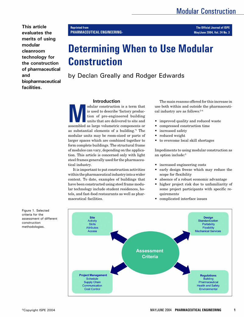
Modular Construction
MAY/JUNE 2004 PHARMACEUTICAL ENGINEERING 1©Copyright ISPE 2004
Figure 1. Selectedcriteria for theassessment of differentconstructionmethodologies.
Determining When to Use ModularConstructionby Declan Greally and Rodger Edwards
This articleevaluates themerits of usingmodularcleanroomtechnology forthe constructionof pharmaceuticalandbiopharmaceuticalfacilities.
Introduction
Modular construction is a term thatis used to describe ‘factory produc-tion of pre-engineered buildingunits that are delivered to site and
assembled as large volumetric components oras substantial elements of a building.’1 Themodular units may be room-sized or parts oflarger spaces which are combined together toform complete buildings. The structural frameof modules can vary, depending on the applica-tion. This article is concerned only with lightsteel frames generally used for the pharmaceu-tical industry.
It is important to put construction activitieswithin the pharmaceutical industry into a widercontext. To date, examples of buildings thathave been constructed using steel frame modu-lar technology include student residences, ho-tels, and fast-food restaurants as well as phar-maceutical facilities.
The main reasons offered for this increase inuse both within and outside the pharmaceuti-cal industry are as follows:2-4
• improved quality and reduced waste• compressed construction time• increased safety• reduced weight• to overcome local skill shortages
Impediments to using modular construction asan option include:5
• increased engineering costs• early design freeze which may reduce the
scope for flexibility• absence of a robust economic advantage• higher project risk due to unfamiliarity of
some project participants with specific re-quirements
• complicated interface issues
Reprinted from The Official Journal of ISPE
PHARMACEUTICAL ENGINEERING® May/June 2004, Vol. 24 No. 3
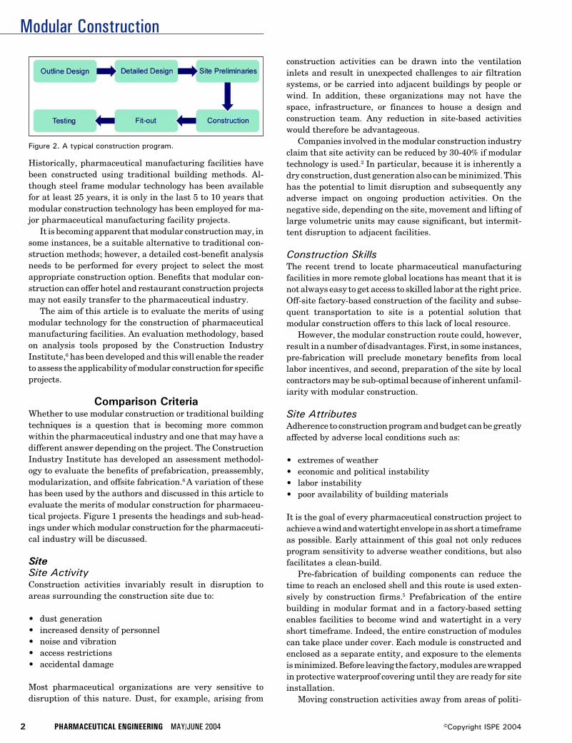
Modular Construction
2 PHARMACEUTICAL ENGINEERING MAY/JUNE 2004 ©Copyright ISPE 2004
Figure 2. A typical construction program.
Historically, pharmaceutical manufacturing facilities havebeen constructed using traditional building methods. Al-though steel frame modular technology has been availablefor at least 25 years, it is only in the last 5 to 10 years thatmodular construction technology has been employed for ma-jor pharmaceutical manufacturing facility projects.
It is becoming apparent that modular construction may, insome instances, be a suitable alternative to traditional con-struction methods; however, a detailed cost-benefit analysisneeds to be performed for every project to select the mostappropriate construction option. Benefits that modular con-struction can offer hotel and restaurant construction projectsmay not easily transfer to the pharmaceutical industry.
The aim of this article is to evaluate the merits of usingmodular technology for the construction of pharmaceuticalmanufacturing facilities. An evaluation methodology, basedon analysis tools proposed by the Construction IndustryInstitute,6 has been developed and this will enable the readerto assess the applicability of modular construction for specificprojects.
Comparison CriteriaWhether to use modular construction or traditional buildingtechniques is a question that is becoming more commonwithin the pharmaceutical industry and one that may have adifferent answer depending on the project. The ConstructionIndustry Institute has developed an assessment methodol-ogy to evaluate the benefits of prefabrication, preassembly,modularization, and offsite fabrication.6 A variation of thesehas been used by the authors and discussed in this article toevaluate the merits of modular construction for pharmaceu-tical projects. Figure 1 presents the headings and sub-head-ings under which modular construction for the pharmaceuti-cal industry will be discussed.
SiteSite ActivityConstruction activities invariably result in disruption toareas surrounding the construction site due to:
• dust generation• increased density of personnel• noise and vibration• access restrictions• accidental damage
Most pharmaceutical organizations are very sensitive todisruption of this nature. Dust, for example, arising from
construction activities can be drawn into the ventilationinlets and result in unexpected challenges to air filtrationsystems, or be carried into adjacent buildings by people orwind. In addition, these organizations may not have thespace, infrastructure, or finances to house a design andconstruction team. Any reduction in site-based activitieswould therefore be advantageous.
Companies involved in the modular construction industryclaim that site activity can be reduced by 30-40% if modulartechnology is used.2 In particular, because it is inherently adry construction, dust generation also can be minimized. Thishas the potential to limit disruption and subsequently anyadverse impact on ongoing production activities. On thenegative side, depending on the site, movement and lifting oflarge volumetric units may cause significant, but intermit-tent disruption to adjacent facilities.
Construction SkillsThe recent trend to locate pharmaceutical manufacturingfacilities in more remote global locations has meant that it isnot always easy to get access to skilled labor at the right price.Off-site factory-based construction of the facility and subse-quent transportation to site is a potential solution thatmodular construction offers to this lack of local resource.
However, the modular construction route could, however,result in a number of disadvantages. First, in some instances,pre-fabrication will preclude monetary benefits from locallabor incentives, and second, preparation of the site by localcontractors may be sub-optimal because of inherent unfamil-iarity with modular construction.
Site AttributesAdherence to construction program and budget can be greatlyaffected by adverse local conditions such as:
• extremes of weather• economic and political instability• labor instability• poor availability of building materials
It is the goal of every pharmaceutical construction project toachieve a wind and watertight envelope in as short a timeframeas possible. Early attainment of this goal not only reducesprogram sensitivity to adverse weather conditions, but alsofacilitates a clean-build.
Pre-fabrication of building components can reduce thetime to reach an enclosed shell and this route is used exten-sively by construction firms.5 Prefabrication of the entirebuilding in modular format and in a factory-based settingenables facilities to become wind and watertight in a veryshort timeframe. Indeed, the entire construction of modulescan take place under cover. Each module is constructed andenclosed as a separate entity, and exposure to the elementsis minimized. Before leaving the factory, modules are wrappedin protective waterproof covering until they are ready for siteinstallation.
Moving construction activities away from areas of politi-
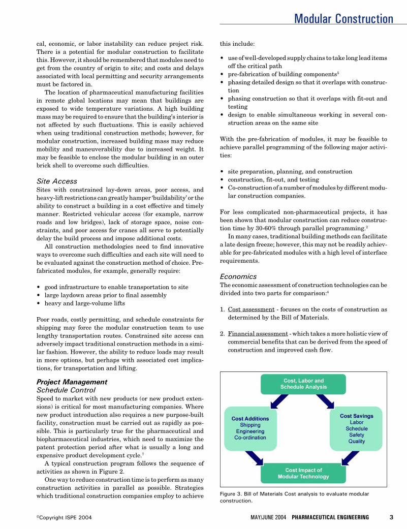
Modular Construction
MAY/JUNE 2004 PHARMACEUTICAL ENGINEERING 3©Copyright ISPE 2004
Figure 3. Bill of Materials Cost analysis to evaluate modularconstruction.
cal, economic, or labor instability can reduce project risk.There is a potential for modular construction to facilitatethis. However, it should be remembered that modules need toget from the country of origin to site; and costs and delaysassociated with local permitting and security arrangementsmust be factored in.
The location of pharmaceutical manufacturing facilitiesin remote global locations may mean that buildings areexposed to wide temperature variations. A high buildingmass may be required to ensure that the building’s interior isnot affected by such fluctuations. This is easily achievedwhen using traditional construction methods; however, formodular construction, increased building mass may reducemobility and maneuverability due to increased weight. Itmay be feasible to enclose the modular building in an outerbrick shell to overcome such difficulties.
Site AccessSites with constrained lay-down areas, poor access, andheavy-lift restrictions can greatly hamper ‘buildability’ or theability to construct a building in a cost effective and timelymanner. Restricted vehicular access (for example, narrowroads and low bridges), lack of storage space, noise con-straints, and poor access for cranes all serve to potentiallydelay the build process and impose additional costs.
All construction methodologies need to find innovativeways to overcome such difficulties and each site will need tobe evaluated against the construction method of choice. Pre-fabricated modules, for example, generally require:
• good infrastructure to enable transportation to site• large laydown areas prior to final assembly• heavy and large-volume lifts
Poor roads, costly permitting, and schedule constraints forshipping may force the modular construction team to uselengthy transportation routes. Constrained site access canadversely impact traditional construction methods in a simi-lar fashion. However, the ability to reduce loads may resultin more options, but perhaps with associated cost implica-tions, for transportation and lifting.
Project ManagementSchedule ControlSpeed to market with new products (or new product exten-sions) is critical for most manufacturing companies. Wherenew product introduction also requires a new purpose-builtfacility, construction must be carried out as rapidly as pos-sible. This is particularly true for the pharmaceutical andbiopharmaceutical industries, which need to maximize thepatent protection period after what is usually a long andexpensive product development cycle.7
A typical construction program follows the sequence ofactivities as shown in Figure 2.
One way to reduce construction time is to perform as manyconstruction activities in parallel as possible. Strategieswhich traditional construction companies employ to achieve
this include:
• use of well-developed supply chains to take long lead itemsoff the critical path
• pre-fabrication of building components5
• phasing detailed design so that it overlaps with construc-tion
• phasing construction so that it overlaps with fit-out andtesting
• design to enable simultaneous working in several con-struction areas on the same site
With the pre-fabrication of modules, it may be feasible toachieve parallel programming of the following major activi-ties:
• site preparation, planning, and construction• construction, fit-out, and testing• Co-construction of a number of modules by different modu-
lar construction companies.
For less complicated non-pharmaceutical projects, it hasbeen shown that modular construction can reduce construc-tion time by 30-60% through parallel programming.2
In many cases, traditional building methods can facilitatea late design freeze; however, this may not be readily achiev-able for pre-fabricated modules with a high level of interfacerequirements.
EconomicsThe economic assessment of construction technologies can bedivided into two parts for comparison:4
1. Cost assessment - focuses on the costs of construction asdetermined by the Bill of Materials.
2. Financial assessment - which takes a more holistic view ofcommercial benefits that can be derived from the speed ofconstruction and improved cash flow.
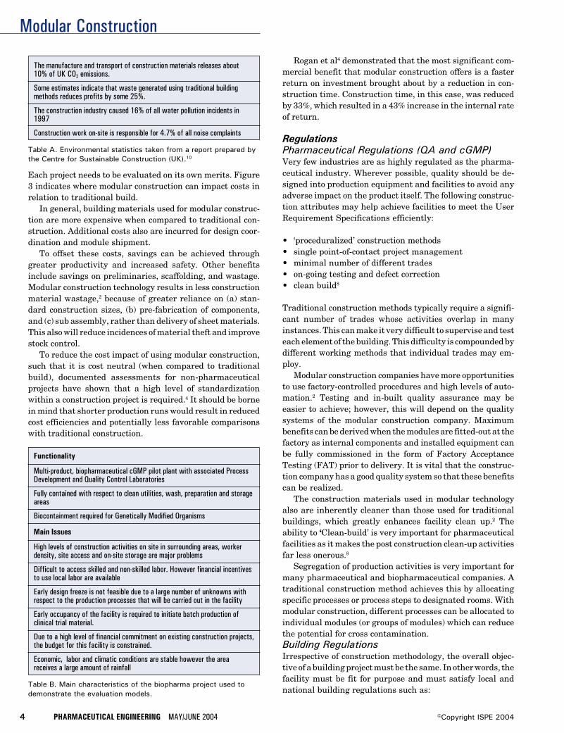
Modular Construction
4 PHARMACEUTICAL ENGINEERING MAY/JUNE 2004 ©Copyright ISPE 2004
Functionality
Multi-product, biopharmaceutical cGMP pilot plant with associated ProcessDevelopment and Quality Control Laboratories
Fully contained with respect to clean utilities, wash, preparation and storageareas
Biocontainment required for Genetically Modified Organisms
Table B. Main characteristics of the biopharma project used todemonstrate the evaluation models.
Main Issues
High levels of construction activities on site in surrounding areas, workerdensity, site access and on-site storage are major problems
Difficult to access skilled and non-skilled labor. However financial incentivesto use local labor are available
Early design freeze is not feasible due to a large number of unknowns withrespect to the production processes that will be carried out in the facility
Early occupancy of the facility is required to initiate batch production ofclinical trial material.
Due to a high level of financial commitment on existing construction projects,the budget for this facility is constrained.
Economic, labor and climatic conditions are stable however the areareceives a large amount of rainfall
Each project needs to be evaluated on its own merits. Figure3 indicates where modular construction can impact costs inrelation to traditional build.
In general, building materials used for modular construc-tion are more expensive when compared to traditional con-struction. Additional costs also are incurred for design coor-dination and module shipment.
To offset these costs, savings can be achieved throughgreater productivity and increased safety. Other benefitsinclude savings on preliminaries, scaffolding, and wastage.Modular construction technology results in less constructionmaterial wastage,2 because of greater reliance on (a) stan-dard construction sizes, (b) pre-fabrication of components,and (c) sub assembly, rather than delivery of sheet materials.This also will reduce incidences of material theft and improvestock control.
To reduce the cost impact of using modular construction,such that it is cost neutral (when compared to traditionalbuild), documented assessments for non-pharmaceuticalprojects have shown that a high level of standardizationwithin a construction project is required.4 It should be bornein mind that shorter production runs would result in reducedcost efficiencies and potentially less favorable comparisonswith traditional construction.
Rogan et al4 demonstrated that the most significant com-mercial benefit that modular construction offers is a fasterreturn on investment brought about by a reduction in con-struction time. Construction time, in this case, was reducedby 33%, which resulted in a 43% increase in the internal rateof return.
RegulationsPharmaceutical Regulations (QA and cGMP)Very few industries are as highly regulated as the pharma-ceutical industry. Wherever possible, quality should be de-signed into production equipment and facilities to avoid anyadverse impact on the product itself. The following construc-tion attributes may help achieve facilities to meet the UserRequirement Specifications efficiently:
• ‘proceduralized’ construction methods• single point-of-contact project management• minimal number of different trades• on-going testing and defect correction• clean build8
Traditional construction methods typically require a signifi-cant number of trades whose activities overlap in manyinstances. This can make it very difficult to supervise and testeach element of the building. This difficulty is compounded bydifferent working methods that individual trades may em-ploy.
Modular construction companies have more opportunitiesto use factory-controlled procedures and high levels of auto-mation.2 Testing and in-built quality assurance may beeasier to achieve; however, this will depend on the qualitysystems of the modular construction company. Maximumbenefits can be derived when the modules are fitted-out at thefactory as internal components and installed equipment canbe fully commissioned in the form of Factory AcceptanceTesting (FAT) prior to delivery. It is vital that the construc-tion company has a good quality system so that these benefitscan be realized.
The construction materials used in modular technologyalso are inherently cleaner than those used for traditionalbuildings, which greatly enhances facility clean up.2 Theability to ‘Clean-build’ is very important for pharmaceuticalfacilities as it makes the post construction clean-up activitiesfar less onerous.8
Segregation of production activities is very important formany pharmaceutical and biopharmaceutical companies. Atraditional construction method achieves this by allocatingspecific processes or process steps to designated rooms. Withmodular construction, different processes can be allocated toindividual modules (or groups of modules) which can reducethe potential for cross contamination.Building RegulationsIrrespective of construction methodology, the overall objec-tive of a building project must be the same. In other words, thefacility must be fit for purpose and must satisfy local andnational building regulations such as:
The manufacture and transport of construction materials releases about10% of UK CO2 emissions.
Some estimates indicate that waste generated using traditional buildingmethods reduces profits by some 25%.
The construction industry caused 16% of all water pollution incidents in1997
Construction work on-site is responsible for 4.7% of all noise complaints
Table A. Environmental statistics taken from a report prepared bythe Centre for Sustainable Construction (UK).10
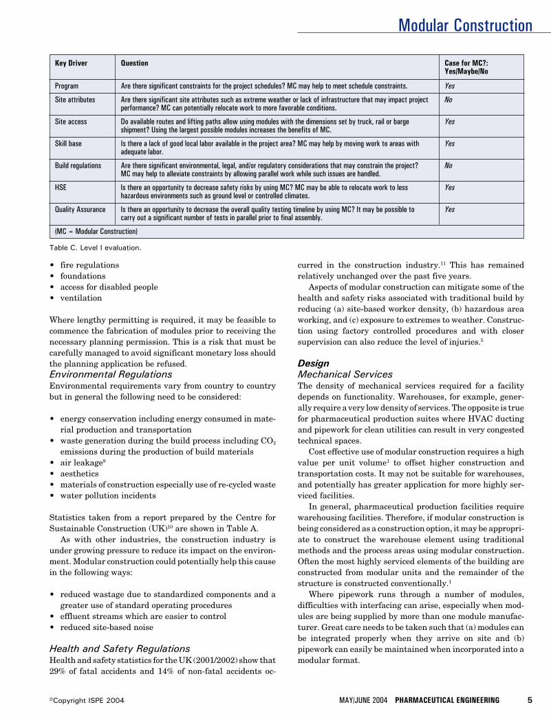
Modular Construction
MAY/JUNE 2004 PHARMACEUTICAL ENGINEERING 5©Copyright ISPE 2004
• fire regulations• foundations• access for disabled people• ventilation
Where lengthy permitting is required, it may be feasible tocommence the fabrication of modules prior to receiving thenecessary planning permission. This is a risk that must becarefully managed to avoid significant monetary loss shouldthe planning application be refused.Environmental RegulationsEnvironmental requirements vary from country to countrybut in general the following need to be considered:
• energy conservation including energy consumed in mate-rial production and transportation
• waste generation during the build process including CO2
emissions during the production of build materials• air leakage9
• aesthetics• materials of construction especially use of re-cycled waste• water pollution incidents
Statistics taken from a report prepared by the Centre forSustainable Construction (UK)10 are shown in Table A.
As with other industries, the construction industry isunder growing pressure to reduce its impact on the environ-ment. Modular construction could potentially help this causein the following ways:
• reduced wastage due to standardized components and agreater use of standard operating procedures
• effluent streams which are easier to control• reduced site-based noise
Health and Safety RegulationsHealth and safety statistics for the UK (2001/2002) show that29% of fatal accidents and 14% of non-fatal accidents oc-
curred in the construction industry.11 This has remainedrelatively unchanged over the past five years.
Aspects of modular construction can mitigate some of thehealth and safety risks associated with traditional build byreducing (a) site-based worker density, (b) hazardous areaworking, and (c) exposure to extremes to weather. Construc-tion using factory controlled procedures and with closersupervision can also reduce the level of injuries.5
DesignMechanical ServicesThe density of mechanical services required for a facilitydepends on functionality. Warehouses, for example, gener-ally require a very low density of services. The opposite is truefor pharmaceutical production suites where HVAC ductingand pipework for clean utilities can result in very congestedtechnical spaces.
Cost effective use of modular construction requires a highvalue per unit volume1 to offset higher construction andtransportation costs. It may not be suitable for warehouses,and potentially has greater application for more highly ser-viced facilities.
In general, pharmaceutical production facilities requirewarehousing facilities. Therefore, if modular construction isbeing considered as a construction option, it may be appropri-ate to construct the warehouse element using traditionalmethods and the process areas using modular construction.Often the most highly serviced elements of the building areconstructed from modular units and the remainder of thestructure is constructed conventionally.1
Where pipework runs through a number of modules,difficulties with interfacing can arise, especially when mod-ules are being supplied by more than one module manufac-turer. Great care needs to be taken such that (a) modules canbe integrated properly when they arrive on site and (b)pipework can easily be maintained when incorporated into amodular format.
Key Driver Question Case for MC?:Yes/Maybe/No
Program Are there significant constraints for the project schedules? MC may help to meet schedule constraints. Yes
Site attributes Are there significant site attributes such as extreme weather or lack of infrastructure that may impact project Noperformance? MC can potentially relocate work to more favorable conditions.
Site access Do available routes and lifting paths allow using modules with the dimensions set by truck, rail or barge Yesshipment? Using the largest possible modules increases the benefits of MC.
Skill base Is there a lack of good local labor available in the project area? MC may help by moving work to areas with Yesadequate labor.
Build regulations Are there significant environmental, legal, and/or regulatory considerations that may constrain the project? NoMC may help to alleviate constraints by allowing parallel work while such issues are handled.
HSE Is there an opportunity to decrease safety risks by using MC? MC may be able to relocate work to less Yeshazardous environments such as ground level or controlled climates.
Quality Assurance Is there an opportunity to decrease the overall quality testing timeline by using MC? It may be possible to Yescarry out a significant number of tests in parallel prior to final assembly.
(MC = Modular Construction)
Table C. Level I evaluation.
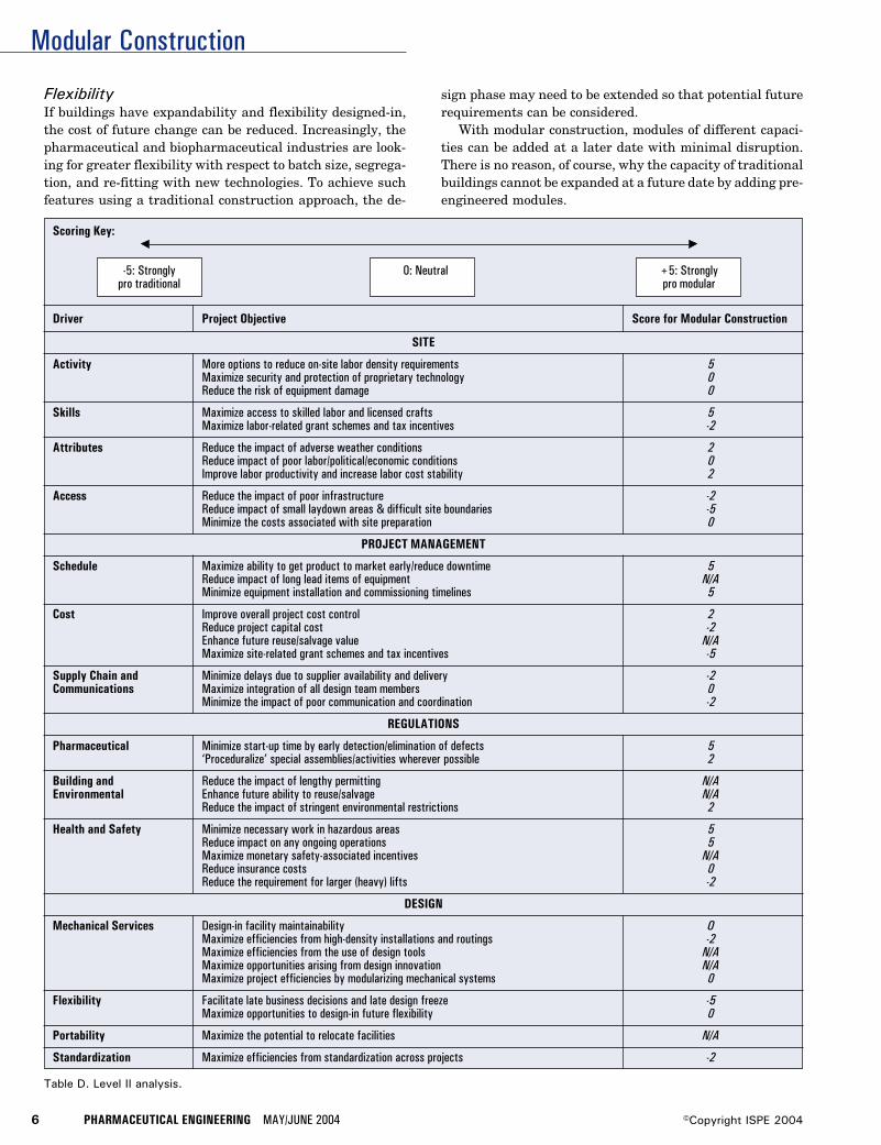
Modular Construction
6 PHARMACEUTICAL ENGINEERING MAY/JUNE 2004 ©Copyright ISPE 2004
Driver Project Objective Score for Modular Construction
SITE
Activity More options to reduce on-site labor density requirements 5Maximize security and protection of proprietary technology 0Reduce the risk of equipment damage 0
Skills Maximize access to skilled labor and licensed crafts 5Maximize labor-related grant schemes and tax incentives -2
Attributes Reduce the impact of adverse weather conditions 2Reduce impact of poor labor/political/economic conditions 0Improve labor productivity and increase labor cost stability 2
Access Reduce the impact of poor infrastructure -2Reduce impact of small laydown areas & difficult site boundaries -5Minimize the costs associated with site preparation 0
PROJECT MANAGEMENT
Schedule Maximize ability to get product to market early/reduce downtime 5Reduce impact of long lead items of equipment N/AMinimize equipment installation and commissioning timelines 5
Cost Improve overall project cost control 2Reduce project capital cost -2Enhance future reuse/salvage value N/AMaximize site-related grant schemes and tax incentives -5
Supply Chain and Minimize delays due to supplier availability and delivery -2Communications Maximize integration of all design team members 0
Minimize the impact of poor communication and coordination -2
REGULATIONS
Pharmaceutical Minimize start-up time by early detection/elimination of defects 5‘Proceduralize’ special assemblies/activities wherever possible 2
Building and Reduce the impact of lengthy permitting N/AEnvironmental Enhance future ability to reuse/salvage N/A
Reduce the impact of stringent environmental restrictions 2
Health and Safety Minimize necessary work in hazardous areas 5Reduce impact on any ongoing operations 5Maximize monetary safety-associated incentives N/AReduce insurance costs 0Reduce the requirement for larger (heavy) lifts -2
DESIGN
Mechanical Services Design-in facility maintainability OMaximize efficiencies from high-density installations and routings -2Maximize efficiencies from the use of design tools N/AMaximize opportunities arising from design innovation N/AMaximize project efficiencies by modularizing mechanical systems 0
Flexibility Facilitate late business decisions and late design freeze -5Maximize opportunities to design-in future flexibility 0
Portability Maximize the potential to relocate facilities N/A
Standardization Maximize efficiencies from standardization across projects -2
Table D. Level II analysis.
Scoring Key:
-5: Strongly 0: Neutral +5: Stronglypro traditional pro modular
FlexibilityIf buildings have expandability and flexibility designed-in,the cost of future change can be reduced. Increasingly, thepharmaceutical and biopharmaceutical industries are look-ing for greater flexibility with respect to batch size, segrega-tion, and re-fitting with new technologies. To achieve suchfeatures using a traditional construction approach, the de-
sign phase may need to be extended so that potential futurerequirements can be considered.
With modular construction, modules of different capaci-ties can be added at a later date with minimal disruption.There is no reason, of course, why the capacity of traditionalbuildings cannot be expanded at a future date by adding pre-engineered modules.
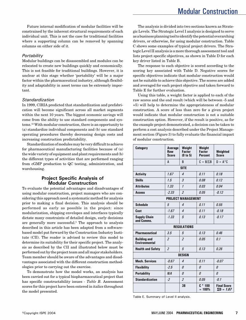
Modular Construction
MAY/JUNE 2004 PHARMACEUTICAL ENGINEERING 7©Copyright ISPE 2004
Future internal modification of modular facilities will beconstrained by the inherent structural requirements of eachindividual unit. This is not the case for traditional facilitieswhere a supporting column can be removed by spanningcolumns on either side of it.
PortabilityModular buildings can be disassembled and modules can berelocated to create new buildings quickly and economically.This is not feasible for traditional buildings. However, it isunclear at this stage whether ‘portability’ will be a majorfactor within the pharmaceutical industry, although flexibil-ity and adaptability in asset terms can be extremely impor-tant.
StandardizationIn 1999, CIRIA predicted that standardization and prefabri-cation will become significant across all market segmentswithin the next 10 years. The biggest economic savings willcome from the ability to use standard components and sys-tems.12 With modular construction, there is an opportunity to(a) standardize individual components and (b) use standardoperating procedures thereby decreasing design costs andincreasing construction predictability.
Standardization of modules may be very difficult to achievefor pharmaceutical manufacturing facilities because of (a)the wide variety of equipment and plant requirements and (b)the different types of activities that are performed rangingfrom cGMP production to QC testing, administration, andwarehousing.
Project Specific Analysis ofModular Construction
To evaluate the potential advantages and disadvantages ofusing modular construction, project managers who are con-sidering this approach need a systematic method for analysisprior to making a final decision. This analysis should beperformed as early as possible in the project: sincemodularization, shipping envelopes and interfaces typicallydictate many constraints of detailed design, early decisionsare generally more successful.5 The approach to analysisdescribed in this article has been adapted from a software-based model put forward by the Construction Industry Insti-tute (CII). The reader is advised to review this model todetermine its suitability for their specific project. The analy-sis as described by the CII and illustrated below must beperformed out by the project team and all major stakeholders.Team member should be aware of the advantages and disad-vantages associated with the different construction method-ologies prior to carrying out the exercise.
To demonstrate how the model works, an analysis hasbeen carried out for a typical biopharmaceutical project thathas specific constructability issues - Table B. Assessmentscores for this project have been entered in italics throughoutthe model presented.
The analysis is divided into two sections known as Strate-gic Levels. The Strategic Level I analysis is designed to serveas a business planning tool to identify the potential overarchingdrivers, or otherwise, for using modular construction. TableC shows some examples of typical project drivers. The Stra-tegic Level II analysis is a more thorough assessment tool andlists project specific objectives, as shown in Table D for eachkey driver listed in Table B.
The response to each objective is scored according to thescoring key associated with Table D. Negative scores forspecific objectives indicate that modular construction wouldnot be suitable to achieve this objective. The scores are addedand averaged for each project objective and taken forward toTable E for further evaluation.
Using this table, a weight factor is applied to each of theraw scores and the end result (which will be between -5 and+5) will help to determine the appropriateness of modularconstruction. A score of less than zero for a given projectwould indicate that modular construction is not a suitableconstruction option. However, if the result is positive, as forthe example project demonstrated, a decision can be taken toperform a cost analysis described under the Project Manage-ment section (Figure 3) to fully evaluate the financial impactof modular construction.
Category Average Weight WeightRaw Factor Factor WeightedScore (0 to 5) Percent Score
A B C = B/ΣB D = A*C
SITE
Activity 1.67 4 0.11 0.18
Skills 1.5 3 0.08 0.12
Attributes 1.33 1 0.03 0.04
Access -2.33 2 0.05 -0.12
PROJECT MANAGEMENT
Schedule 5 4 0.11 0.55
Cost -1.67 4 0.11 -0.18
Supply Chain -1.33 5 0.13 -0.17and Comms.
REGULATIONS
Pharmaceutical 3.5 5 0.13 0.46
Building and 2 2 0.05 0.1Environmental
Health and Safety 2 5 0.13 0.26
DESIGN
Mech. Services -0.67 4 0.11 -0.07
Flexibility -2.5 0 0 0
Portability N/A 0 0 0
Standardization -2 2 0.05 -0.1
38 C * 100 Final Score= 100% ΣΣΣΣΣD = 1.07
Table E. Summary of Level II analysis.
Modular Construction
8 PHARMACEUTICAL ENGINEERING MAY/JUNE 2004 ©Copyright ISPE 2004
SummaryFor many types of buildings, modular construction technol-ogy is becoming a recognized alternative to traditional con-struction. The reasons for this include: shorter constructionperiod, increased opportunities to improve quality, increasedopportunities to increase safety, and advances in construc-tion technology, communication, and design tools
Many factors need to be carefully analyzed before makinga decision to use modular construction for pharmaceuticalfacilities. A number of key drivers need to converge so that thenet benefits of modular construction can be realized. Ingeneral, a high level of module standardization is required toensure that this approach is cost effective. For many pharma-ceutical projects, this may be difficult to achieve.
Finally, to achieve the full benefits of modular construc-tion for pharmaceutical manufacturing facilities, it must beevaluated as a build option alongside traditional prior tofacility design.
References1. Lawson, R.M., Grubb, P.J., Prewer, J., and Trebilcock,
P.J., Modular Construction Using Light Steel Framing:An Architect’s Guide. The Steel Construction Institute1999. ISBN 1 85942 096 6.
2. Wilks, N., “Prefabs Sprout,” Professional Engineering,Vol. 16, No. 9, May 21, 2003.
3. Howell, G., and Ballard, G., Implementing Lean Con-struction: Understanding and Action Proceedings IGLC1998.
4. Rogan, A.L., Lawson, R.M., and Bates-Brkljac, N., Valueand Benefits Assessment of Modular Construction, Pub-lished by The Steel Construction Institute in associationwith Oxford Brookes University for the Modular Mattersconference, London, Sept 2000.
5. Haas, C.T., and Fagerlund, W.R., Preliminary Researchon Prefabrication, Preassembly, Modularisation and Off-Site Fabrication in Construction. A report to the Con-struction Industry Institute July 2002.
6. Construction Industry Institute. Implementing the Pre-fabrication, Preassembly, Modularization and Off-SiteFabrication Decision Framework: Guide and Tool, Sept2002.
7. Chasey, A., A Comparison of Clean Protocol ApproachesDuring the Construction Process. Proceedings from theISPE Winter Conference, 17-20 February 2003.
8. CIRIA briefing paper. UK Construction 2010 - FutureTrends and Issues, 1999.
9. Greally, D., and Edwards, R., “Transferring a GeneticallyEngineered Biopharmaceutical from Research to ClinicalDevelopment - Impact on Facility Design and Build
Projects,” Pharmaceutical Engineering, Vol. 22, No. 4,August 2002.
10. Approved Document, Building Regulations for Englandand Wales, HMSO, April 2002.
11. HSE statistics 2001/2002.
12. Howard, N., Sustainable Construction - The Data, Pre-pared for the Centre for Sustainable Construction, March2000.
About the AuthorsDeclan Greally, BSc MSc, is a Pharmaceu-tical Specialist with Amec Ltd. He is a gradu-ate of biotechnology from Dublin City Univer-sity and has more than 16 years of industrialexperience in the diagnostic and pharmaceu-tical industries. Greally completed his MSc inpharmaceutical engineering Advanced Train-ing from UMIST in 1999. His experience spans
from operations (mainly sterile products) in process develop-ment/production/scale-up to technology transfer ofbiopharmaceutical and pharmaceutical products. Technologytransfer of products has involved the design/build/validation ofnew facilities, the preparation of production, and regulatorydocumentation, and finally, the recruitment and training of aproduction team. He can be reached by email:[email protected].
Amec Group Ltd., Sankey House, 130 Birchwood Blvd.,Birchwood, Warrington, Cheshire WA3 7WD, United King-dom.
Rodger Edwards graduated with a BSc(Honors) in metallurgy and materials sci-ence from the joint UMIST/University ofManchester Department of Metallurgy in1979 and then spent three years as a re-search student in the same department, re-searching thermophysical properties of liq-uid metals. He joined the Department of
Building Engineering at UMIST as a research assistant in1983 with his main research areas being the measurement ofventilation rates using tracer gases and the computer simu-lation of hot water systems. He finally obtained his PhD fromUMIST in 1986. In 1987, he was appointed as a lecturer in theDepartment of Building Engineering at UMIST, and in 1997was promoted to Senior Lecturer. He was elected to member-ship of the Chartered Institution of Building Services Engi-neers (CIBSE) in the same year. Edwards has been theDirector of the Pharmaceutical Engineering Advanced Train-ing (PEAT) program since December 1996, and has super-vised more than 40 successful MSc graduates through theirdissertations. He is also a Faculty Tutor at UMIST, and isChairman of the Merseyside and North Wales Region ofCIBSE. He has been an ISPE member since 1996.
UMIST, Dept. of Building Engineering, PO Box 88,Sackville St., Manchester M60 1QD, United Kingdom.
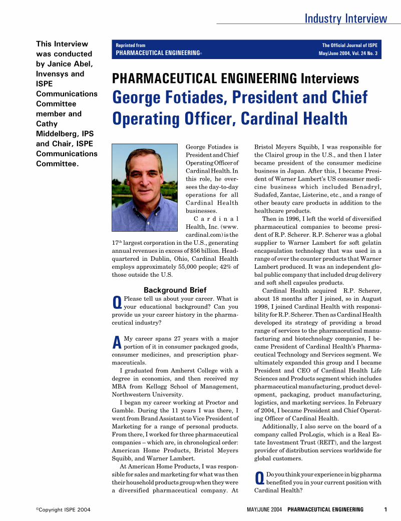
Industry Interview
MAY/JUNE 2004 PHARMACEUTICAL ENGINEERING 1©Copyright ISPE 2004
This Interviewwas conductedby Janice Abel,Invensys andISPECommunicationsCommitteemember andCathyMiddelberg, IPSand Chair, ISPECommunicationsCommittee.
George Fotiades isPresident and ChiefOperating Officer ofCardinal Health. Inthis role, he over-sees the day-to-dayoperations for allCardinal Healthbusinesses.
C a r d i n a lHealth, Inc. (www.cardinal.com) is the
17th largest corporation in the U.S., generatingannual revenues in excess of $56 billion. Head-quartered in Dublin, Ohio, Cardinal Healthemploys approximately 55,000 people; 42% ofthose outside the U.S.
Background Brief
Q Please tell us about your career. What isyour educational background? Can you
provide us your career history in the pharma-ceutical industry?
A My career spans 27 years with a majorportion of it in consumer packaged goods,
consumer medicines, and prescription phar-maceuticals.
I graduated from Amherst College with adegree in economics, and then received myMBA from Kellogg School of Management,Northwestern University.
I began my career working at Proctor andGamble. During the 11 years I was there, Iwent from Brand Assistant to Vice President ofMarketing for a range of personal products.From there, I worked for three pharmaceuticalcompanies – which are, in chronological order:American Home Products, Bristol MeyersSquibb, and Warner Lambert.
At American Home Products, I was respon-sible for sales and marketing for what was thentheir household products group when they werea diversified pharmaceutical company. At
Bristol Meyers Squibb, I was responsible forthe Clairol group in the U.S., and then I laterbecame president of the consumer medicinebusiness in Japan. After this, I became Presi-dent of Warner Lambert’s US consumer medi-cine business which included Benadryl,Sudafed, Zantac, Listerine, etc., and a range ofother beauty care products in addition to thehealthcare products.
Then in 1996, I left the world of diversifiedpharmaceutical companies to become presi-dent of R.P. Scherer. R.P. Scherer was a globalsupplier to Warner Lambert for soft gelatinencapsulation technology that was used in arange of over the counter products that WarnerLambert produced. It was an independent glo-bal public company that included drug deliveryand soft shell capsules products.
Cardinal Health acquired R.P. Scherer,about 18 months after I joined, so in August1998, I joined Cardinal Health with responsi-bility for R.P. Scherer. Then as Cardinal Healthdeveloped its strategy of providing a broadrange of services to the pharmaceutical manu-facturing and biotechnology companies, I be-came President of Cardinal Health’s Pharma-ceutical Technology and Services segment. Weultimately expanded this group and I becamePresident and CEO of Cardinal Health LifeSciences and Products segment which includespharmaceutical manufacturing, product devel-opment, packaging, product manufacturing,logistics, and marketing services. In Februaryof 2004, I became President and Chief Operat-ing Officer of Cardinal Health.
Additionally, I also serve on the board of acompany called ProLogis, which is a Real Es-tate Investment Trust (REIT), and the largestprovider of distribution services worldwide forglobal customers.
Q Do you think your experience in big pharmabenefited you in your current position with
Cardinal Health?
PHARMACEUTICAL ENGINEERING InterviewsGeorge Fotiades, President and ChiefOperating Officer, Cardinal Health
Reprinted from The Official Journal of ISPE
PHARMACEUTICAL ENGINEERING® May/June 2004, Vol. 24 No. 3
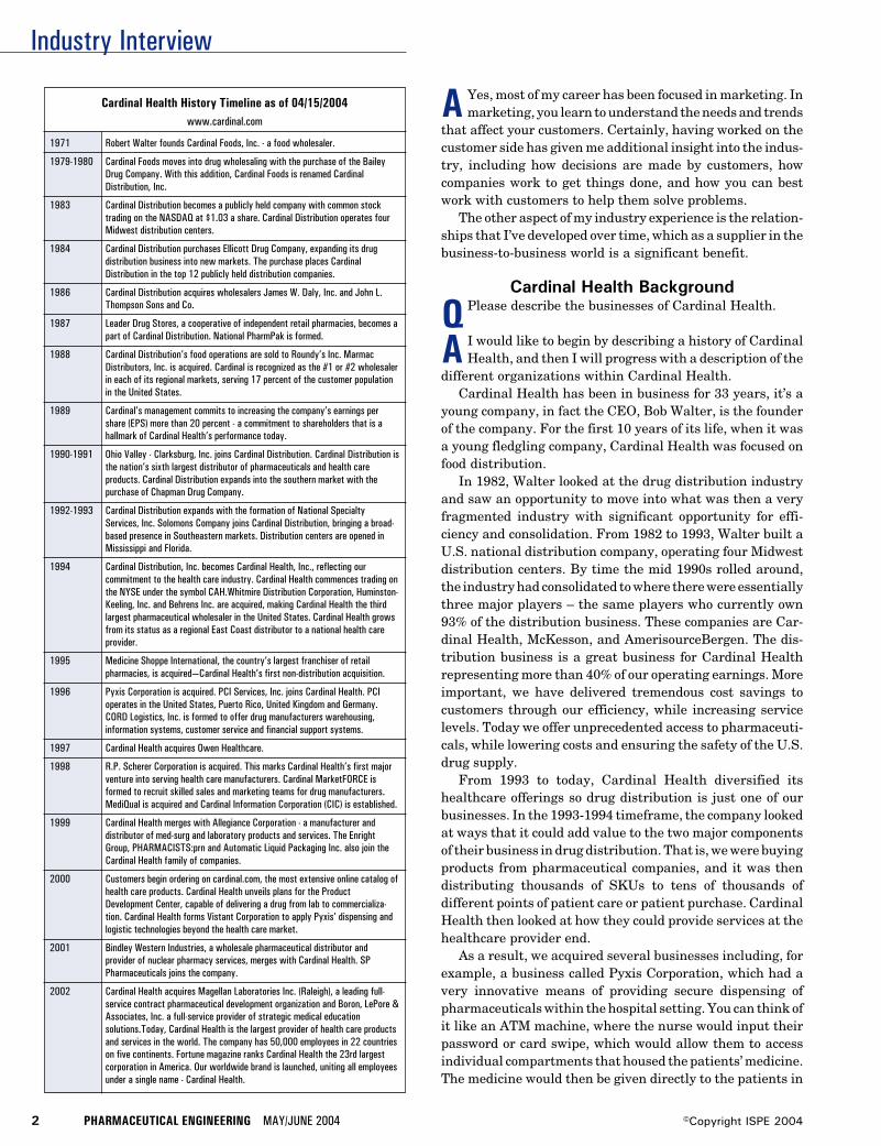
Industry Interview
2 PHARMACEUTICAL ENGINEERING MAY/JUNE 2004 ©Copyright ISPE 2004
A Yes, most of my career has been focused in marketing. Inmarketing, you learn to understand the needs and trends
that affect your customers. Certainly, having worked on thecustomer side has given me additional insight into the indus-try, including how decisions are made by customers, howcompanies work to get things done, and how you can bestwork with customers to help them solve problems.
The other aspect of my industry experience is the relation-ships that I’ve developed over time, which as a supplier in thebusiness-to-business world is a significant benefit.
Cardinal Health Background
Q Please describe the businesses of Cardinal Health.
A I would like to begin by describing a history of CardinalHealth, and then I will progress with a description of the
different organizations within Cardinal Health.Cardinal Health has been in business for 33 years, it’s a
young company, in fact the CEO, Bob Walter, is the founderof the company. For the first 10 years of its life, when it wasa young fledgling company, Cardinal Health was focused onfood distribution.
In 1982, Walter looked at the drug distribution industryand saw an opportunity to move into what was then a veryfragmented industry with significant opportunity for effi-ciency and consolidation. From 1982 to 1993, Walter built aU.S. national distribution company, operating four Midwestdistribution centers. By time the mid 1990s rolled around,the industry had consolidated to where there were essentiallythree major players – the same players who currently own93% of the distribution business. These companies are Car-dinal Health, McKesson, and AmerisourceBergen. The dis-tribution business is a great business for Cardinal Healthrepresenting more than 40% of our operating earnings. Moreimportant, we have delivered tremendous cost savings tocustomers through our efficiency, while increasing servicelevels. Today we offer unprecedented access to pharmaceuti-cals, while lowering costs and ensuring the safety of the U.S.drug supply.
From 1993 to today, Cardinal Health diversified itshealthcare offerings so drug distribution is just one of ourbusinesses. In the 1993-1994 timeframe, the company lookedat ways that it could add value to the two major componentsof their business in drug distribution. That is, we were buyingproducts from pharmaceutical companies, and it was thendistributing thousands of SKUs to tens of thousands ofdifferent points of patient care or patient purchase. CardinalHealth then looked at how they could provide services at thehealthcare provider end.
As a result, we acquired several businesses including, forexample, a business called Pyxis Corporation, which had avery innovative means of providing secure dispensing ofpharmaceuticals within the hospital setting. You can think ofit like an ATM machine, where the nurse would input theirpassword or card swipe, which would allow them to accessindividual compartments that housed the patients’ medicine.The medicine would then be given directly to the patients in
Cardinal Health History Timeline as of 04/15/2004www.cardinal.com
1971 Robert Walter founds Cardinal Foods, Inc. - a food wholesaler.
1979-1980 Cardinal Foods moves into drug wholesaling with the purchase of the BaileyDrug Company. With this addition, Cardinal Foods is renamed CardinalDistribution, Inc.
1983 Cardinal Distribution becomes a publicly held company with common stocktrading on the NASDAQ at $1.03 a share. Cardinal Distribution operates fourMidwest distribution centers.
1984 Cardinal Distribution purchases Ellicott Drug Company, expanding its drugdistribution business into new markets. The purchase places CardinalDistribution in the top 12 publicly held distribution companies.
1986 Cardinal Distribution acquires wholesalers James W. Daly, Inc. and John L.Thompson Sons and Co.
1987 Leader Drug Stores, a cooperative of independent retail pharmacies, becomes apart of Cardinal Distribution. National PharmPak is formed.
1988 Cardinal Distribution’s food operations are sold to Roundy’s Inc. MarmacDistributors, Inc. is acquired. Cardinal is recognized as the #1 or #2 wholesalerin each of its regional markets, serving 17 percent of the customer populationin the United States.
1989 Cardinal’s management commits to increasing the company’s earnings pershare (EPS) more than 20 percent - a commitment to shareholders that is ahallmark of Cardinal Health’s performance today.
1990-1991 Ohio Valley - Clarksburg, Inc. joins Cardinal Distribution. Cardinal Distribution isthe nation’s sixth largest distributor of pharmaceuticals and health careproducts. Cardinal Distribution expands into the southern market with thepurchase of Chapman Drug Company.
1992-1993 Cardinal Distribution expands with the formation of National SpecialtyServices, Inc. Solomons Company joins Cardinal Distribution, bringing a broad-based presence in Southeastern markets. Distribution centers are opened inMississippi and Florida.
1994 Cardinal Distribution, Inc. becomes Cardinal Health, Inc., reflecting ourcommitment to the health care industry. Cardinal Health commences trading onthe NYSE under the symbol CAH.Whitmire Distribution Corporation, Huminston-Keeling, Inc. and Behrens Inc. are acquired, making Cardinal Health the thirdlargest pharmaceutical wholesaler in the United States. Cardinal Health growsfrom its status as a regional East Coast distributor to a national health careprovider.
1995 Medicine Shoppe International, the country’s largest franchiser of retailpharmacies, is acquired—Cardinal Health’s first non-distribution acquisition.
1996 Pyxis Corporation is acquired. PCI Services, Inc. joins Cardinal Health. PCIoperates in the United States, Puerto Rico, United Kingdom and Germany.CORD Logistics, Inc. is formed to offer drug manufacturers warehousing,information systems, customer service and financial support systems.
1997 Cardinal Health acquires Owen Healthcare.
1998 R.P. Scherer Corporation is acquired. This marks Cardinal Health’s first majorventure into serving health care manufacturers. Cardinal MarketFORCE isformed to recruit skilled sales and marketing teams for drug manufacturers.MediQual is acquired and Cardinal Information Corporation (CIC) is established.
1999 Cardinal Health merges with Allegiance Corporation - a manufacturer anddistributor of med-surg and laboratory products and services. The EnrightGroup, PHARMACISTS:prn and Automatic Liquid Packaging Inc. also join theCardinal Health family of companies.
2000 Customers begin ordering on cardinal.com, the most extensive online catalog ofhealth care products. Cardinal Health unveils plans for the ProductDevelopment Center, capable of delivering a drug from lab to commercializa-tion. Cardinal Health forms Vistant Corporation to apply Pyxis’ dispensing andlogistic technologies beyond the health care market.
2001 Bindley Western Industries, a wholesale pharmaceutical distributor andprovider of nuclear pharmacy services, merges with Cardinal Health. SPPharmaceuticals joins the company.
2002 Cardinal Health acquires Magellan Laboratories Inc. (Raleigh), a leading full-service contract pharmaceutical development organization and Boron, LePore &Associates, Inc. a full-service provider of strategic medical educationsolutions.Today, Cardinal Health is the largest provider of health care productsand services in the world. The company has 50,000 employees in 22 countrieson five continents. Fortune magazine ranks Cardinal Health the 23rd largestcorporation in America. Our worldwide brand is launched, uniting all employeesunder a single name - Cardinal Health.
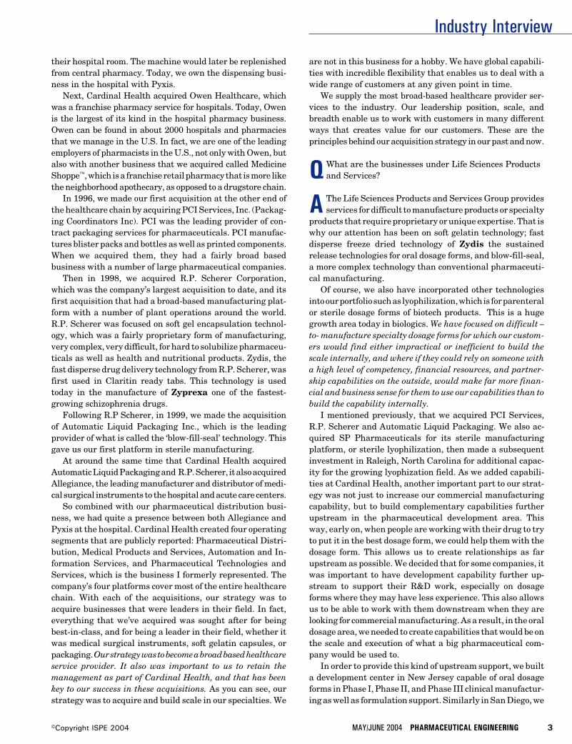
Industry Interview
MAY/JUNE 2004 PHARMACEUTICAL ENGINEERING 3©Copyright ISPE 2004
their hospital room. The machine would later be replenishedfrom central pharmacy. Today, we own the dispensing busi-ness in the hospital with Pyxis.
Next, Cardinal Health acquired Owen Healthcare, whichwas a franchise pharmacy service for hospitals. Today, Owenis the largest of its kind in the hospital pharmacy business.Owen can be found in about 2000 hospitals and pharmaciesthat we manage in the U.S. In fact, we are one of the leadingemployers of pharmacists in the U.S., not only with Owen, butalso with another business that we acquired called MedicineShoppe™, which is a franchise retail pharmacy that is more likethe neighborhood apothecary, as opposed to a drugstore chain.
In 1996, we made our first acquisition at the other end ofthe healthcare chain by acquiring PCI Services, Inc. (Packag-ing Coordinators Inc). PCI was the leading provider of con-tract packaging services for pharmaceuticals. PCI manufac-tures blister packs and bottles as well as printed components.When we acquired them, they had a fairly broad basedbusiness with a number of large pharmaceutical companies.
Then in 1998, we acquired R.P. Scherer Corporation,which was the company’s largest acquisition to date, and itsfirst acquisition that had a broad-based manufacturing plat-form with a number of plant operations around the world.R.P. Scherer was focused on soft gel encapsulation technol-ogy, which was a fairly proprietary form of manufacturing,very complex, very difficult, for hard to solubilize pharmaceu-ticals as well as health and nutritional products. Zydis, thefast disperse drug delivery technology from R.P. Scherer, wasfirst used in Claritin ready tabs. This technology is usedtoday in the manufacture of Zyprexa one of the fastest-growing schizophrenia drugs.
Following R.P Scherer, in 1999, we made the acquisitionof Automatic Liquid Packaging Inc., which is the leadingprovider of what is called the ‘blow-fill-seal’ technology. Thisgave us our first platform in sterile manufacturing.
At around the same time that Cardinal Health acquiredAutomatic Liquid Packaging and R.P. Scherer, it also acquiredAllegiance, the leading manufacturer and distributor of medi-cal surgical instruments to the hospital and acute care centers.
So combined with our pharmaceutical distribution busi-ness, we had quite a presence between both Allegiance andPyxis at the hospital. Cardinal Health created four operatingsegments that are publicly reported: Pharmaceutical Distri-bution, Medical Products and Services, Automation and In-formation Services, and Pharmaceutical Technologies andServices, which is the business I formerly represented. Thecompany’s four platforms cover most of the entire healthcarechain. With each of the acquisitions, our strategy was toacquire businesses that were leaders in their field. In fact,everything that we’ve acquired was sought after for beingbest-in-class, and for being a leader in their field, whether itwas medical surgical instruments, soft gelatin capsules, orpackaging. Our strategy was to become a broad based healthcareservice provider. It also was important to us to retain themanagement as part of Cardinal Health, and that has beenkey to our success in these acquisitions. As you can see, ourstrategy was to acquire and build scale in our specialties. We
are not in this business for a hobby. We have global capabili-ties with incredible flexibility that enables us to deal with awide range of customers at any given point in time.
We supply the most broad-based healthcare provider ser-vices to the industry. Our leadership position, scale, andbreadth enable us to work with customers in many differentways that creates value for our customers. These are theprinciples behind our acquisition strategy in our past and now.
QWhat are the businesses under Life Sciences Productsand Services?
A The Life Sciences Products and Services Group providesservices for difficult to manufacture products or specialty
products that require proprietary or unique expertise. That iswhy our attention has been on soft gelatin technology; fastdisperse freeze dried technology of Zydis the sustainedrelease technologies for oral dosage forms, and blow-fill-seal,a more complex technology than conventional pharmaceuti-cal manufacturing.
Of course, we also have incorporated other technologiesinto our portfolio such as lyophilization, which is for parenteralor sterile dosage forms of biotech products. This is a hugegrowth area today in biologics. We have focused on difficult –to- manufacture specialty dosage forms for which our custom-ers would find either impractical or inefficient to build thescale internally, and where if they could rely on someone witha high level of competency, financial resources, and partner-ship capabilities on the outside, would make far more finan-cial and business sense for them to use our capabilities than tobuild the capability internally.
I mentioned previously, that we acquired PCI Services,R.P. Scherer and Automatic Liquid Packaging. We also ac-quired SP Pharmaceuticals for its sterile manufacturingplatform, or sterile lyophilization, then made a subsequentinvestment in Raleigh, North Carolina for additional capac-ity for the growing lyophization field. As we added capabili-ties at Cardinal Health, another important part to our strat-egy was not just to increase our commercial manufacturingcapability, but to build complementary capabilities furtherupstream in the pharmaceutical development area. Thisway, early on, when people are working with their drug to tryto put it in the best dosage form, we could help them with thedosage form. This allows us to create relationships as farupstream as possible. We decided that for some companies, itwas important to have development capability further up-stream to support their R&D work, especially on dosageforms where they may have less experience. This also allowsus to be able to work with them downstream when they arelooking for commercial manufacturing. As a result, in the oraldosage area, we needed to create capabilities that would be onthe scale and execution of what a big pharmaceutical com-pany would be used to.
In order to provide this kind of upstream support, we builta development center in New Jersey capable of oral dosageforms in Phase I, Phase II, and Phase III clinical manufactur-ing as well as formulation support. Similarly in San Diego, we
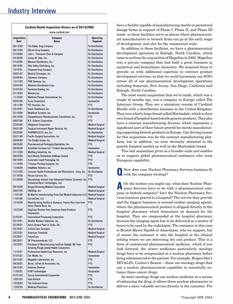
Industry Interview
4 PHARMACEUTICAL ENGINEERING MAY/JUNE 2004 ©Copyright ISPE 2004
Cardinal Health Acquisition History as of 04/15/2004www.cardinal.com
Acquisition Company OperatingDate Name Segment
05/12/80 The Bailey Drug Company Rx Distribution09/14/84 Ellicott Drug Company Rx Distribution01/20/86 John L. Thompson Sons & Company Rx Distribution04/30/86 James W. Daly, Inc. Rx Distribution01/20/88 Marmac Distributors, Inc. Rx Distribution06/18/90 Ohio Valley-Clarksburg, Inc. Rx Distribution10/15/91 Chapman Drug Company Rx Distribution04/01/92 Medical Strategies, Inc. Rx Distribution05/04/93 Solomons Company Rx Distribution12/17/93 PRN Services, Inc. Rx Distribution02/07/94 Whitmire Distribution Corp. Rx Distribution07/01/94 Humiston-Keeling, Inc. Rx Distribution07/18/94 Behrens Inc. Rx Distribution11/13/95 Medicine Shoppe International, Inc. Rx Distribution05/07/96 Pyxis Corporation Automation10/11/96 PCI Services, Inc. PTS03/18/97 Owen Healthcare, Inc. Rx Distribution02/18/98 MediQual Systems, Inc. Automation05/15/98 Comprehensive Reimbursement Consultants, Inc. PTS08/07/98 R.P. Scherer Corporation PTS02/03/99 Allegiance Corporation Medical-Surgical04/01/99 Surgical Instrument Repair Services, Inc. Medical-Surgical05/20/99 PHARMACISTS: prn, Inc. Rx Distribution05/21/99 Pacific Surgical Innovations, Inc. Medical-Surgical06/04/99 The Enright Group, Inc. Medical-Surgical06/25/99 Pharmaceutical Packaging Specialties, Inc. PTS06/30/99 AutoValet Systems Intl - Product line purchase Automation07/12/99 MedSurg Industries, Inc. Medical-Surgical08/25/99 Herd Mundy Richardson Holdings Limited PTS09/10/99 Automatic Liquid Packaging, Inc. PTS11/18/99 Trimaras Printing Company, Inc. PTS12/30/99 HelpMate Robotics, Inc. Automation01/21/00 Contract Health Professionals and Pharmacists - Ance, Inc. Rx Distribution07/19/00 Rexam Cartons, Inc. PTS07/26/00 Dermatology division from Advanced Polymer Systerms, Inc. PTS
(Enhanced Derm Technologies, Inc)08/16/00 Bergen Brunswig Medical Corporation Medical-Surgical09/01/00 ENDOlap, Inc. Medical-Surgical11/01/00 Ni-Med kit manufacturing (from Oak Medical Industries LLC) Medical-Surgical11/01/00 CurranCare, LLC Medical-Surgical12/15/00 Manufacturing Facility in Humacao, Puerto Rico from from PTS
Alcon (Puerto Rico), Inc.12/22/00 VegiCaps Division from American Home Products PTS
Corporation01/02/01 International Processing Corporation PTS02/14/01 Bindley Western Industries, Inc. Rx Distribution02/26/01 Astra-Zeneca Plant in Corby, UK PTS03/16/01 Critical Care Concepts Medical-Surgical03/23/01 American Threshold Medical-Surgical03/28/01 FutureCare Medical-Surgical06/29/01 SP Pharmaceuticals, LLC. PTS10/23/01 Purchase of Manufacturing facilityin Raleigh, NC from PTS
Schering-Plough animal Health Corporation.11/15/01 Professional Health-Care Resources, Inc. Medical-Surgical01/07/02 Eon Media, Inc. Automation04/15/02 Magellan Laboratories, Inc. PTS06/26/02 Boron, LePore & Associates, Inc. PTS08/15/02 Atlantes Services Automation11/05/02 KVM Technologies Automation01/01/03 Syncor International Corporation PTS10/01/03 Gala Biotech PTS10/29/03 The Intercare Group PTS12/02/03 Medicap Pharmaces Rx Distribution
have a facility capable of manufacturing sterile or parenteraldosage forms in support of Phase I, Phase II, and Phase IIItrials- so these facilities serve as places where pharmaceuti-cal manufacturers or biotech firms can go at the early stageof development, and also for the commercial scale.
In addition to these facilities, we have a pharmaceuticaldevelopment operation in Raleigh, North Carolina, whichcame to us from the acquisition of Magellan in 2002. Magellanwas a private company that had built a great business inanalytical and formulation chemistry. We acquired them toprovide us with additional expertise in contract productdevelopment services, so that we could harmonize our SOPsacross all of our pharmaceutical development operationsincluding Somerset, New Jersey, San Diego, California andRaleigh, North Carolina.
The most recent acquisition that we’ve made, which was acouple of months ago, was a company in Europe called TheIntercare Group. They are a miniature version of CardinalHealth with a distribution business in the United Kingdom.They own a fairly large brand called Martindale, which is theirown brand of hospital-based sterile generic products. They alsohave a contract manufacturing division, which represents asignificant part of their future growth for sterile manufactur-ing supporting biotech products in Europe. Our driving reasonfor this acquisition was for the contract manufacturing plat-form, but in addition, we were obviously attracted to thegeneric hospital market as well as the Martindale brand.
This last acquisition gives us a broader scale and enablesus to support global pharmaceutical customers who wantEuropean capability.
QHow does your Nuclear Pharmacy Services business fitwith the company strategy?
A On the surface you might say, what does Nuclear Phar-macy Services have to do with a pharmaceutical com-
pany or biotech company? Isn’t the Nuclear Pharmacy Ser-vices business geared to a hospital? The service they provideand the biggest business is around cardiac imaging agents,where the pharmaceutical product is shipped directly to thehospital pharmacy which formulates on demand for thehospital. They are compounded at the hospital pharmacybecause the imaging agent has to be delivered in a matter ofhours to be used by the radiologist. The customer in this caseis Bristol-Myers Squibb or Amersham, who we support, butof course the customer is also the hospital in the clinicalsetting where we are delivering the end product. This is aform of customized pharmaceutical medicine, which if youlook forward, the newer medicines particularly oncologydrugs have to be compounded at a nuclear pharmacy beforebeing administered to the patient. For example, Biogen Idec’sZEVALIN, Coulter’s Bexxar – these are oncology drugs thatuse a nuclear pharmaceutical capability to essentially en-hance these cancer drugs.
As more oncology drugs use nuclear medicine as a meansof enhancing the drug, it allows these nuclear pharmacies todeliver a more valuable service directly to the customer. For
Industry Interview
MAY/JUNE 2004 PHARMACEUTICAL ENGINEERING 5©Copyright ISPE 2004
ZEVALIN, the material is delivered to our nuclear pharmacy,and then the drug is compounded into its final form where itis then administered to the patient. Likewise for Coulter’sBexxar. The nuclear pharmacy has value in situations wheremedicines need to be to be customized at the patient levelbefore administering and/or has characteristics which re-quire unique logistics. For example, if the half-life of theproduct is incredibly short, which is the case with the prod-ucts just described, a nuclear pharmacy is valuable becauseit has the ability to do the final formulation work and it hasthe logistics to support delivery to thousands of locations orpoints of care in a matter of hours.
Q Describe the growth within Cardinal Health’s Life Sci-ences business.
A The Life Sciences and Products segment represents 20%of Cardinal Health’s earnings, $3 billion revenue, and
supports about 20 to 25 pharmaceutical products at themanufacturing pricing level. We have about 40 plant opera-tions around the world today, 25 of them are FDA approvedfacilities, and a larger number than that are approved by thelocal authorities in their specific locations.
We’ve created the broadest offering in the marketplace forthese kinds of services to pharma and biotech people. We seethe company‘s growth in a couple of ways. Big pharma compa-nies are going through a large transformation in how they dobusiness particularly in terms of productivity - gaining moreproductivity in product development and also looking at waysat managing costs differently, particularly with price pres-sures. The other growth driver focus is biotech companies.There is no shortage of biotech companies, nor will there be.There are a growing number of products in the biotech pipe-line. And many of these companies are wisely choosing not toinvest in infrastructure that is unrelated to drug development,because if they can go out and find a partner like ourselves todevelop, manufacture, and distribute the products, they cankeep their precious dollars focused on getting the drug ap-proved. We can support them from end to end.
QWhat do you see as the opportunities for Cardinal Healthin contract manufacturing?
A Within Cardinal Health, we operate in neat operatinggroups, we see the greatest opportunity for the company in
continuing to integrate the capabilities we have across all ofCardinal Health. The power of that integration becomes veryevident the more we focus around the different business seg-ments that are in the market place and the kind of needs theyhave.
For example, our nuclear pharmacy business can workwith the product of a big pharmaceutical company or abiotech company that requires work at the nuclear pharmacyto add a nuclear isotope to make it a better drug and then useus for the logistics to get it to the hospital. At the hospitallevel, our presence in having a strong hospital franchisethrough our medical products and services group and our
distribution group can have large benefits to our nuclearpharmacy services group in terms of influencing marketshare for products that are made in our nuclear pharmacyservices business.
If you look at the oncology segment, we can work ononcology products as a pharmaceutical development com-pany or we can help manufacture them, but we also can helpdistribute these products to the oncologist’s office, which issomething that occurs on the other “side” of Cardinal Health.The point is that when we take a look from the outside in, thereal power of our organization in the future is in its ability tohave multiple touch points in healthcare. That visibilityallows us to identify the needs of individual segments like abiotech company, or a company focused on oncology products,or the ability to deliver in the hospital segment or thephysician’s office. These are ways we can create value - bycombining different segments of Cardinal Health. That isreally where we see some great opportunities for us goingforward. These opportunities are significant for us becausewe are a young company. With everything that is happeningin healthcare today, there is still a need for more efficiencyand the need for more effectiveness. A company that has allthese touch points in healthcare can do an awful lot to createvalue for people. We are very much focused on how we canintegrate our company, work with customers at senior levelswithin organizations, with people who have a view of theentire spectrum of what they are trying to accomplish as acompany, but we also recognize where we need to be success-ful is at the working level for each individual project, whereyou are only as good as what you’ve accomplished yesterday,so that’s an important component too. Obviously we arelooking to build on the strength we are starting to create byhaving all these touch points in a specialty where there is aninsatiable demand for figuring out ways to be more efficientor to create better drugs.
Q Do you now, or will you in the future, develop, manufac-ture, and market your own products?
A No, by and large we are predominantly focused on en-abling other people’s pharmaceutical products.
QWhere are your development and manufacturing facili-ties located?
A Our facilities are located in 11 countries as follows:• 28 medical/surgical manufacturing plants and 47
medical/surgical distribution centers• 24 pharmaceutical distribution centers in the U.S.• 38 pharmaceutical manufacturing, laboratory, and
packaging facilities
QWhat is driving expansion within the CMO or CPObusiness?
A The use of outsource providers are driven by differentneeds for big pharma and the biotech industry.
Industry Interview
6 PHARMACEUTICAL ENGINEERING MAY/JUNE 2004 ©Copyright ISPE 2004
Big pharma is working to dramatically change their coststructure and focus on improving the productivity of theirR&D pipeline. One of the ways they are looking to managecosts is by streamlining the supply chain, which up to now hasbeen managed internally. They also are looking for supportand services for difficult to manufacture products or forspecialty manufacturing processes that require proprietaryor unique expertise. As the pressure on healthcare costsaccelerates, big pharma will look at outsource providers asstrategic partners who can reliably deliver better service atreduced cost.
Because biotech companies are choosing not to invest ininfrastructure unrelated to drug development, they are look-ing to outsource providers with expertise in manufacturingand support services. Bioprocesses typically include lyo-philization and aseptic processing. Cardinal Health has ex-panded their sterile manufacturing capabilities in the U.S.and Europe, providing a platform and scale to support globalpharmaceutical customers. The logistics of producing tar-geted drugs and delivering to the clinic, hospital, or patientbedside also creates a distribution opportunity for an outsourceprovider who has these services.
QWhat are the biggest risks in contract manufacturing?
A A general risk we might face is one where an investmentis required on our part. We then must understand what
the return on that investment will be. This requires us to becloser to the client or the market to understand the products wework on, to understand the market place, and to understandthe regulatory issues. Obviously, we have to manage this muchlike a portfolio; we don’t want 100% of what we do to be highrisk business because there is tremendous economic return injust the fee for service business, which has far less risk.
QWhat is the main concern your clients have in usingcontract manufacturers?
A I think most people would like to say it is cost, but by farthe most important concern is quality and reliability. The
demand for quality from industry, from customers, and fromregulatory authorities has increased substantially. Not only isit incredibly important to be a compliant manufacturer/pro-vider, you must be a highly reliable one; you do what you say andyou deliver what you promise. Cost comes after this.
QHow do you address the variations in product packaging,formulation, or manufacturing processes with multiple
clients?
A In contrast to captive manufacturing facilities, our op-erations are designed to be highly flexible. We have made
a huge investment in scale to have that flexibility. We spenda lot of time optimizing the utilization of our assets. Thismeans we focus a great deal on changeover time and how toreduce the time it takes for changes. We focus on cleaningvalidation and how to do that efficiently.
QWhat current or pending regulations will have the big-gest effect on the contract manufacturing business?
A I think the biggest focus today is the systems basedregulatory approach the FDA adopted not long ago.
Previously, they had a specific product focus, now they arefocused on the integrity of the key systems within the plant.For a contract manufacturer the size of Cardinal Health, wehave to have consistency in our practices across a wide rangeof plants. This is both for the benefit of the authorities and forour customers. From a contract manufacturer’s point of view,we can’t afford any mistakes because our livelihood is builtaround being able to persuade our customers that they canrely on us without supply interruption. If you get into trouble,you disappoint the FDA, yourself, the client, and the patient.It can taint your reputation, which can impact your business.For us, regulatory has to be a core competency.
The focus on perfect quality is going to continue to accel-erate, requiring improved manufacturing systems and pro-cesses. The challenge will be the implementation of improve-ments without regulatory obstruction.
QHow will Medicare reform and cost containment mea-sures imposed by governments and private insurers
around the world affect the CMO business?
A If there is going to be an effect, it will be a positive one.Medicare reform will to some degree increase pharma-
ceutical consumption, resulting in increased manufacturingand distribution. So I think greater access is good for every-body, including the patient.
Cost containment measures are going to increase the focus onhow to get more efficiency out of the supply chain. This maymean that industry will look to outsource even more so that theycan reduce their own cost and the infrastructure dedicated tomanufacturing and increase their investments in drug develop-ment or sales and marketing. I don’t believe we have seen thefull brunt of this effect in industry, but the trend is there.
QHow is Cardinal Health addressing the security issues ofproduct distribution?
A Cardinal Health has done a considerable amount toprotect the integrity of the supply chain. The big trend
now underway is Just-In-Time (JIT) manufacturing for phar-maceutical products. In the past, pharmaceutical manufac-turers have encouraged a buy and hold mentality, which hasresulted in a large amount of inventory in the supply chain.This has created a large secondary market for arbitrage,selling drugs to smaller organizations whose sole purpose isto resell the drug at a profit. As the industry moves to JITmanufacturing, the inventory in the supply chain will bereduced, minimizing the opportunity for illegal diversion ofproducts.
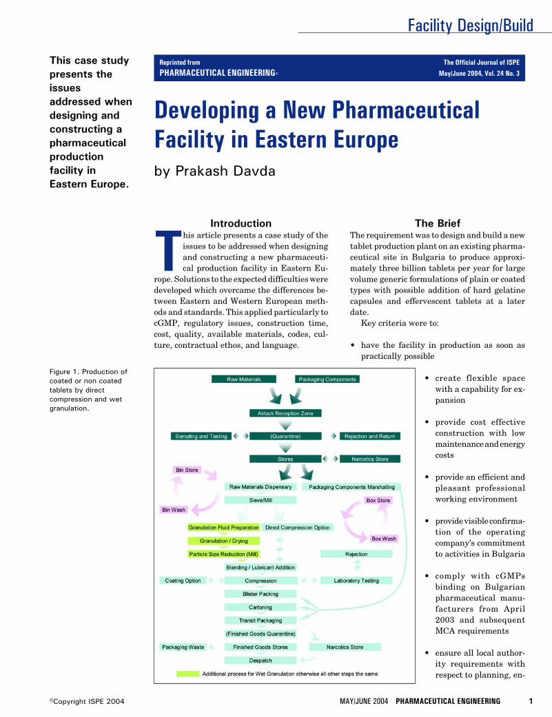
Facility Design/Build
MAY/JUNE 2004 PHARMACEUTICAL ENGINEERING 1©Copyright ISPE 2004
Developing a New PharmaceuticalFacility in Eastern Europeby Prakash Davda
This case studypresents theissuesaddressed whendesigning andconstructing apharmaceuticalproductionfacility inEastern Europe.
Figure 1. Production ofcoated or non coatedtablets by directcompression and wetgranulation.
Introduction
This article presents a case study of theissues to be addressed when designingand constructing a new pharmaceuti-cal production facility in Eastern Eu-
rope. Solutions to the expected difficulties weredeveloped which overcame the differences be-tween Eastern and Western European meth-ods and standards. This applied particularly tocGMP, regulatory issues, construction time,cost, quality, available materials, codes, cul-ture, contractual ethos, and language.
The BriefThe requirement was to design and build a newtablet production plant on an existing pharma-ceutical site in Bulgaria to produce approxi-mately three billion tablets per year for largevolume generic formulations of plain or coatedtypes with possible addition of hard gelatinecapsules and effervescent tablets at a laterdate.
Key criteria were to:
• have the facility in production as soon aspractically possible
• create flexible spacewith a capability for ex-pansion
• provide cost effectiveconstruction with lowmaintenance and energycosts
• provide an efficient andpleasant professionalworking environment
• provide visible confirma-tion of the operatingcompany’s commitmentto activities in Bulgaria
• comply with cGMPsbinding on Bulgarianpharmaceutical manu-facturers from April2003 and subsequentMCA requirements
• ensure all local author-ity requirements withrespect to planning, en-
Reprinted from The Official Journal of ISPE
PHARMACEUTICAL ENGINEERING® May/June 2004, Vol. 24 No. 3
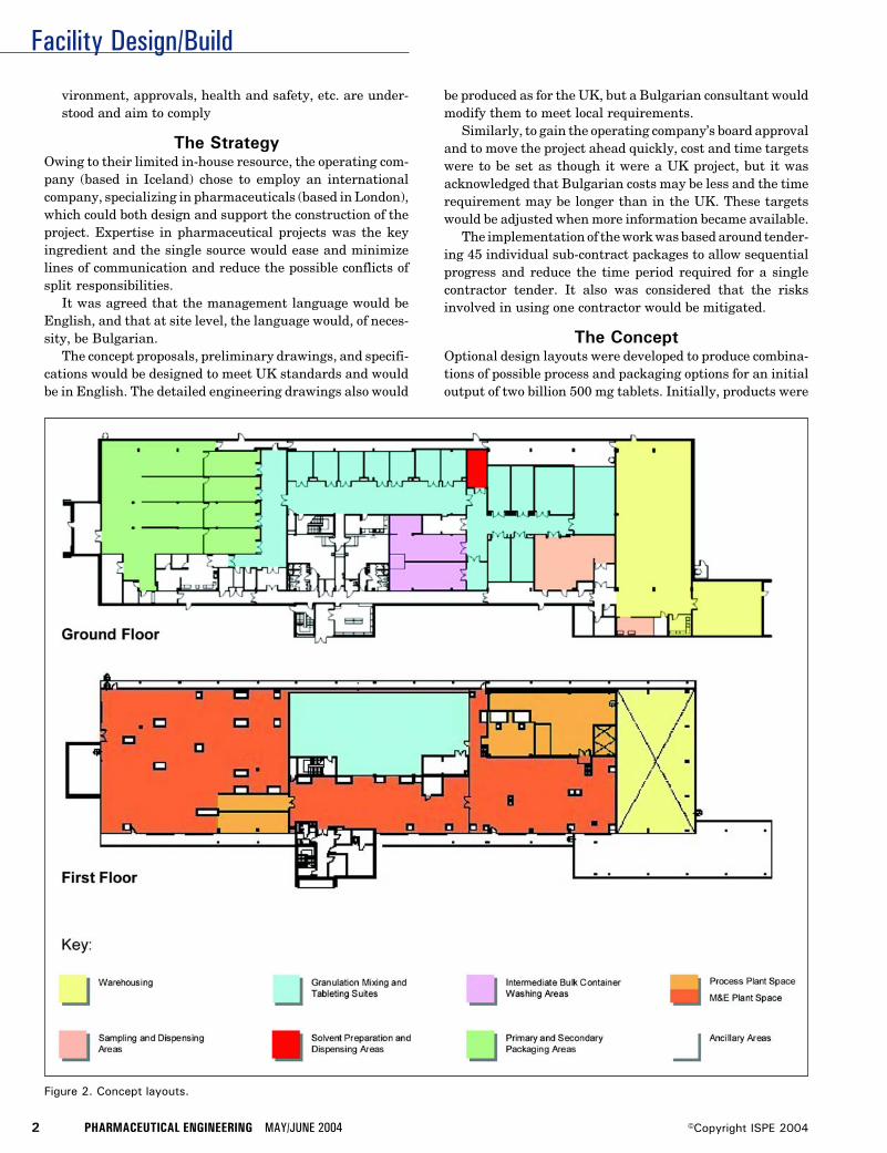
Facility Design/Build
2 PHARMACEUTICAL ENGINEERING MAY/JUNE 2004 ©Copyright ISPE 2004
Figure 2. Concept layouts.
vironment, approvals, health and safety, etc. are under-stood and aim to comply
The StrategyOwing to their limited in-house resource, the operating com-pany (based in Iceland) chose to employ an internationalcompany, specializing in pharmaceuticals (based in London),which could both design and support the construction of theproject. Expertise in pharmaceutical projects was the keyingredient and the single source would ease and minimizelines of communication and reduce the possible conflicts ofsplit responsibilities.
It was agreed that the management language would beEnglish, and that at site level, the language would, of neces-sity, be Bulgarian.
The concept proposals, preliminary drawings, and specifi-cations would be designed to meet UK standards and wouldbe in English. The detailed engineering drawings also would
be produced as for the UK, but a Bulgarian consultant wouldmodify them to meet local requirements.
Similarly, to gain the operating company’s board approvaland to move the project ahead quickly, cost and time targetswere to be set as though it were a UK project, but it wasacknowledged that Bulgarian costs may be less and the timerequirement may be longer than in the UK. These targetswould be adjusted when more information became available.
The implementation of the work was based around tender-ing 45 individual sub-contract packages to allow sequentialprogress and reduce the time period required for a singlecontractor tender. It also was considered that the risksinvolved in using one contractor would be mitigated.
The ConceptOptional design layouts were developed to produce combina-tions of possible process and packaging options for an initialoutput of two billion 500 mg tablets. Initially, products were
Facility Design/Build
MAY/JUNE 2004 PHARMACEUTICAL ENGINEERING 3©Copyright ISPE 2004
to be solvent based followed subsequently with aqueousbased.
The variances developed were based on the following:• Two billion 13 mm (500 mg) tablets by direct compression
- uncoated• Four billion 7-9 mm (250 mg) tablets by direct compression
- uncoated• 1.5 billion 10 mm (250mg) tablets by wet granulation• One billion coated tablets• 1.5 billion tablets in blister packs - minimum of 10 tablets
per carton
The above figures were dependent on achieving good OverallEquipment Efficiencies (OEE) and this was difficult to deter-mine in Bulgaria. In practice, during start-up, the learningcurve involved would influence the OEE.
The capacity of the plant was to be doubled with theintroduction of additional process equipment. However, itwas initially based on two shifts: seven hour days x five daysover 250 working days per year.
To develop the processes, generic production proceduresas depicted in Figure 1 were used to establish the outlinerequirements.
An optimum layout as indicated in Figure 2 was agreedbased on the operating and design company’s experience of theneeds in Iceland and the UK while ensuring full compliance toregulatory requirements. The Bulgarian operators and engi-neers agreed with the layout and flow arrangements. Never-theless, based on their experiences in Eastern Europe, theybelieved the facility should be 20% larger than the planned4,600 sq.m. (49,725 sq.ft.) solution. This was their view on mostelements of the design – large ‘built in’ factors of safety.
The agreed scheme allowed for a sampling booth, twodispensing booths, two granulation and fluid bed dryer suites,blending, six tablet press suites, two coating suites, onecapsule filling suite, automatic IBC wash station, four blisterpackaging, cartoning and over-wrapping suites, and gener-ous work in progress areas with design for future expansion.
The Preliminary DesignTo keep the project moving quickly, a decision was made toundertake preliminary engineering using UK design stan-dards, but modified to take into account the known Bulgarianstandards at that time.
A review was made of Bulgarian methods, capabilities,and their ability to meet known Western standards. Al-though masonry was the normal form of construction for thebuilding envelope, steel and metal cladding were available atreasonable cost, although not commonly used. This wasconsidered desirable for speed and flexibility for the future.Internal finishes were available to meet the required cGMPs.However, application techniques were yet to be explored.
Basic Bulgarian design codes were incorporated into thepreliminary design, such as seismic codes, floor, roof andwind loadings, summer and winter dry and wet bulb condi-tions.
The concept design was developed using the information
obtained, but maintaining the operational and cGMP fea-tures.
All production areas were designated to Class 100,000.However the design was to consider achieving Class 10,000 inthe future without involving any major modification to theconstruction, fabric, or finishes.
Pressure regimes were established whereby movement ofair through the various areas satisfied the requirements forcontainment of powders and elimination of risk of cross con-tamination. At the same time, all designated clean areas fordispensing, production, and packaging were maintained atpositive pressure (10Pa) relative to external atmospheric pres-sure, thereby preventing ingress of unclean air from outside.
The possibility of manufacturing effervescent tablets meantcertain production areas required a low humidity environ-ment. This was achieved by incorporating regenerative chemi-cal dehumidifiers on systems serving the specified areas.
The cleanroom pressures, temperatures, and humiditieswere designed to be monitored by a Validated BuildingManagement System which would have the capacity to moni-tor and record all room data for a year’s operation. The systemwas designed to provide a separate “back up” facility.
The central pure water system was designed to providepure water to USP24 standard to serve clean-in-place sys-tems, IBC automatic wash station, laboratories, and smallparts wash areas.
To minimize operational cost of the air conditioning sys-tems, the ratio of fresh air to re-circulated air was selected at20% to 80%. To avoid any cross contamination with this highpercentage of re-circulated air, filters were installed on thereturn air systems in addition to the main EU 11-HEPAfilters on the supply systems.
Estimating the cost of the building, services, and processequipment was based on UK costs although it was recognizedthat the cost of the building should be less than the equivalentin the UK so a comfort factor was built in.
All new production and packaging equipment was sourcedand costed from Western Europe suppliers.
Similarly, a design and construction program was pro-duced as though the facility were to be designed and con-structed in the UK, which would give a challenging target forBulgarian sub-contractors.
Based on the 30 preliminary drawings, the cost plan andprogram produced, the board members of the operatingcompany were able to confidently make an informed decisionthat the proposed solution would meet their business planrequirements for the Bulgarian facility.
Local Authority RequirementsIn order for the UK staff to understand the local authorityapproval process, considerable time and effort was devoted tothe subject as some of the materials, methods, and techniquesused in Western Europe were not generally available inEastern Europe. Importing material was not an easy optionas it would take time for them to be accepted by localauthorities. This caused several difficulties throughout theproject, requiring very careful discussion and negotiations
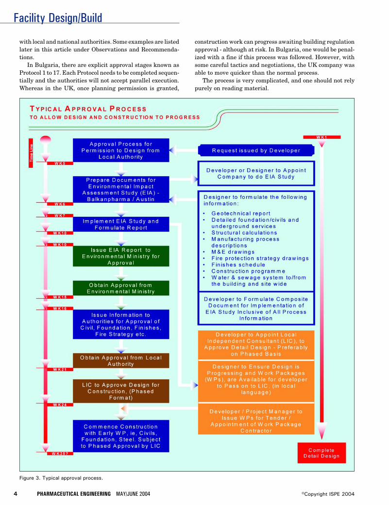
Facility Design/Build
4 PHARMACEUTICAL ENGINEERING MAY/JUNE 2004 ©Copyright ISPE 2004
Figure 3. Typical approval process.
with local and national authorities. Some examples are listedlater in this article under Observations and Recommenda-tions.
In Bulgaria, there are explicit approval stages known asProtocol 1 to 17. Each Protocol needs to be completed sequen-tially and the authorities will not accept parallel execution.Whereas in the UK, once planning permission is granted,
construction work can progress awaiting building regulationapproval - although at risk. In Bulgaria, one would be penal-ized with a fine if this process was followed. However, withsome careful tactics and negotiations, the UK company wasable to move quicker than the normal process.
The process is very complicated, and one should not relypurely on reading material.
Facility Design/Build
MAY/JUNE 2004 PHARMACEUTICAL ENGINEERING 5©Copyright ISPE 2004
Before one considers all protocols in detail, Protocol 1 isthe most significant - “Permission to Design” and “Permis-sion to Build” is required from the local authority. Thisprocess is described in Figure 3 and is usually initiated by thedeveloper.
Preconstruction Stage Approval ProcessOnce Protocol 1 has been obtained, which could take up to sixmonths, the construction process begins. This is where therequirements must be understood in detail.
Scheduled below is each protocol with information needed.This has been extracted from their National Regulation No 7-22.05.2001 - statements and protocols issued during thebuilding period.
Protocol No 1 - the site is handed over and accepted by theContractor and the design is approved for execution.Formal permission is granted from the Mayor’s officeissued by the Chief Architect.
Protocol No 2 - building site is allowed to formally open toallow building lines and levels to be agreed.
Protocol No 3 - the site book/diary certified from the NationalBuilding Supervision Directorate is issued for recordingall future activities.
Protocol No 4 - formal hand over/acceptance of all technicaldocumentation.
Protocol No 5 - statement for the building terrain certifyingand complying with the detail drawings setting out basebuilding coordinates.
Protocol No 6 - statement certifying soil category and actualexcavating working levels.
Protocol No 7 - statement for acceptance of the actual build-ing/assembling works by levels and details.
Protocol No 8 - statement for acceptance of the foundationworks for construction.
Protocol No 9 - statement for acceptance of the shuttering,reinforcement and welded works.
Protocol No 10 - deviations from the design dimensionsaccording to Regulation No 3 for the acceptance of theconcrete works.
Protocol No 11 - statement for the acceptance and transfer ofequipment.
Protocol No 12 - statement for determining the buildingcondition in case of stopping.
Protocol No 13 - acceptance of the completed metal construc-tion corrosion protection.
Protocol No 14 - determine status of all hidden works:concrete foundations, back fill, lintels, masonry, cavityinsulation, heat insulation, vapor barriers, internal/exter-nal doors, windows, etc. Statement for the building con-struction acceptance.
Protocol No 15 - statement to confirm the building is readyto be accepted for use. This includes:
• completing 72 hours running test on all systems includ-ing mechanical, electrical, drainage, process and pro-duction equipment, lifts, etc. and certificate of conform-ance of any specialist material
• written permission to use imported materials not inaccordance with relevant Bulgarian standards andprotocol from the licensed Bulgarian laboratory for theimported materials approved by the Ministry of Build-ing
• approved detail drawings and statement of compliancewith the design parameters
• Results from 72 hours test on all services. AcceptanceCertificate for completion of all works from the relevantauthorities including the incoming services supply com-pany, the Regional Inspectorate for Environment andWaters etc.
• statements of completion from the Main Contractor
• proof of ownership and permission to build on territoryof someone else’s property – if applicable
• environmental impact assessment
• card for assessment of influence on site environment incomparison with the original samples taken at the start
• certificate for achieving the set design parameterswithin the whole facility
• statement from Occupational Health and Safety Au-thorities allowing the building to go into operation
• statement from the Fire Fighting Emergency RegionalService
• document issued by the Cadastre Agency (Local County)for building survey, underground technical systems,and equipment survey in attendance with the CadastreAgency
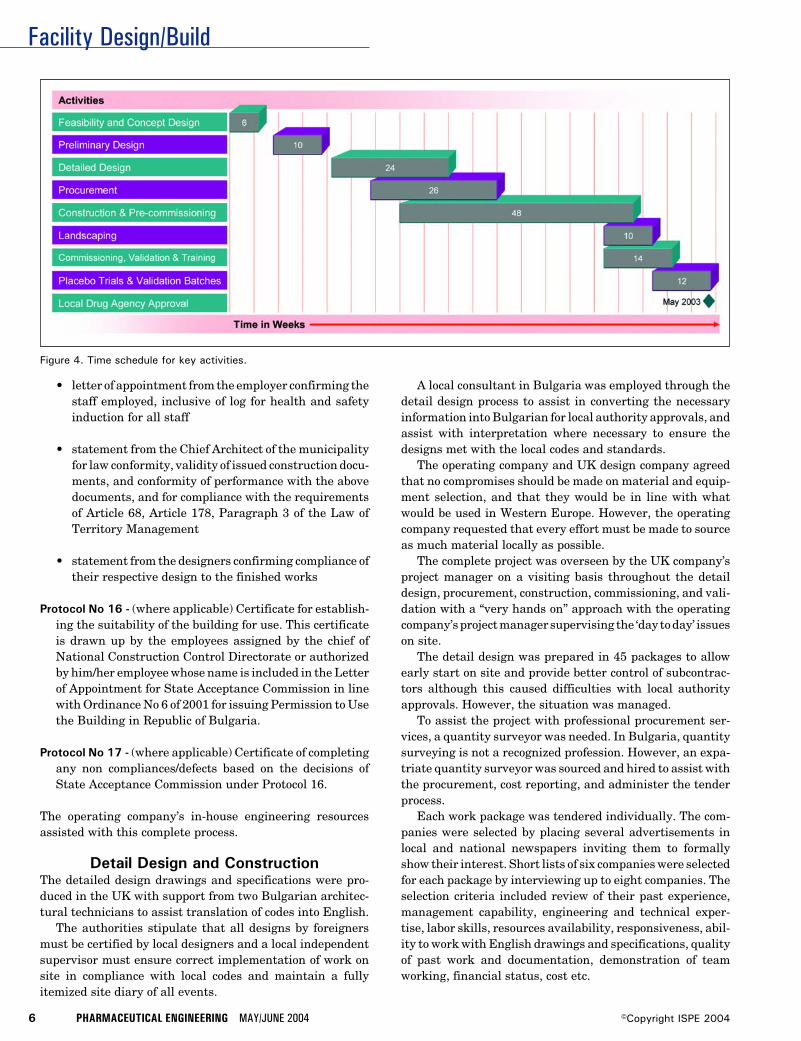
Facility Design/Build
6 PHARMACEUTICAL ENGINEERING MAY/JUNE 2004 ©Copyright ISPE 2004
• letter of appointment from the employer confirming thestaff employed, inclusive of log for health and safetyinduction for all staff
• statement from the Chief Architect of the municipalityfor law conformity, validity of issued construction docu-ments, and conformity of performance with the abovedocuments, and for compliance with the requirementsof Article 68, Article 178, Paragraph 3 of the Law ofTerritory Management
• statement from the designers confirming compliance oftheir respective design to the finished works
Protocol No 16 - (where applicable) Certificate for establish-ing the suitability of the building for use. This certificateis drawn up by the employees assigned by the chief ofNational Construction Control Directorate or authorizedby him/her employee whose name is included in the Letterof Appointment for State Acceptance Commission in linewith Ordinance No 6 of 2001 for issuing Permission to Usethe Building in Republic of Bulgaria.
Protocol No 17 - (where applicable) Certificate of completingany non compliances/defects based on the decisions ofState Acceptance Commission under Protocol 16.
The operating company’s in-house engineering resourcesassisted with this complete process.
Detail Design and ConstructionThe detailed design drawings and specifications were pro-duced in the UK with support from two Bulgarian architec-tural technicians to assist translation of codes into English.
The authorities stipulate that all designs by foreignersmust be certified by local designers and a local independentsupervisor must ensure correct implementation of work onsite in compliance with local codes and maintain a fullyitemized site diary of all events.
A local consultant in Bulgaria was employed through thedetail design process to assist in converting the necessaryinformation into Bulgarian for local authority approvals, andassist with interpretation where necessary to ensure thedesigns met with the local codes and standards.
The operating company and UK design company agreedthat no compromises should be made on material and equip-ment selection, and that they would be in line with whatwould be used in Western Europe. However, the operatingcompany requested that every effort must be made to sourceas much material locally as possible.
The complete project was overseen by the UK company’sproject manager on a visiting basis throughout the detaildesign, procurement, construction, commissioning, and vali-dation with a “very hands on” approach with the operatingcompany’s project manager supervising the ‘day to day’ issueson site.
The detail design was prepared in 45 packages to allowearly start on site and provide better control of subcontrac-tors although this caused difficulties with local authorityapprovals. However, the situation was managed.
To assist the project with professional procurement ser-vices, a quantity surveyor was needed. In Bulgaria, quantitysurveying is not a recognized profession. However, an expa-triate quantity surveyor was sourced and hired to assist withthe procurement, cost reporting, and administer the tenderprocess.
Each work package was tendered individually. The com-panies were selected by placing several advertisements inlocal and national newspapers inviting them to formallyshow their interest. Short lists of six companies were selectedfor each package by interviewing up to eight companies. Theselection criteria included review of their past experience,management capability, engineering and technical exper-tise, labor skills, resources availability, responsiveness, abil-ity to work with English drawings and specifications, qualityof past work and documentation, demonstration of teamworking, financial status, cost etc.
Figure 4. Time schedule for key activities.
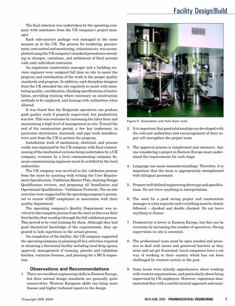
Facility Design/Build
MAY/JUNE 2004 PHARMACEUTICAL ENGINEERING 7©Copyright ISPE 2004
The final selection was undertaken by the operating com-pany with assistance from the UK company’s project man-ager.
Each sub-contract package was managed in the samemanner as in the UK. The process for tendering, procure-ment, cost control and monitoring, valuations etc. was accom-plished using the UK company’s standard procedures extend-ing to changes, variations, and settlement of final accountwith each individual contractor.
An expatriate construction manager and a building ser-vices engineer were assigned full time on site to assist theprogress and coordination of the work to the proper qualitystandards and program. In addition, each discipline designerfrom the UK attended the site regularly to assist with moni-toring quality, coordination, checking specifications of instal-lation, providing training where necessary on constructionmethods to be employed, and liaising with authorities whenallowed.
It was found that the Bulgarian operatives can producegood quality work if properly supervised, but productivitywas low. This was overcome by increasing the labor force andmaintaining a high level of management on site. Toward theend of the construction period, a few key tradesmen, inparticular electricians, ductwork, and pipe work installers,were sent from the UK to protect the program.
Installation work of mechanical, electrical, and processworks was organized by the UK company with final commis-sioning of the mechanical systems being undertaken by a UKcompany, overseen by a local commissioning company be-cause commissioning engineers must be certified by the localauthorities.
The UK company was involved in the validation processfrom the onset by assisting with writing the User Require-ment Specification, Validation Master Plan, chairing DesignQualification reviews, and preparing all Installation andOperational Qualification - Validation Protocols. The on-siteactivities were supported by the operating company’s person-nel to ensure cGMP compliance in association with theirquality department.
The operating company’s Quality Department was in-volved in the complete process from the start as this was theirfirst facility that would go through the full validation process.This proved to be vital training for them. Although they hadgood theoretical knowledge of the requirements, they ap-peared to lack experience in the actual process.
On completion of the facility, the UK company supportedthe operating company in planning all key activities requiredin attaining a functional facility including local drug agencyapproval, management of training, placebo and validationbatches, variation licenses, and planning for a MCA inspec-tion.
Observations and Recommendations1. There are excellent engineering skills in Eastern Europe,
but their normal design standards are generally quiteconservative. Western European skills can bring morefinesse and higher technical inputs to the design
2. It is important that good relationships are developed withthe relevant authorities and encouragement of their in-put will strengthen the project team.
3. The approval process is complicated and extensive. Anyone considering a project in Eastern Europe must under-stand the requirements for each stage.
4. Language can cause misunderstandings. Therefore, it isimportant that the team is appropriately strengthenedwith bilingual personnel.
5. Prepare well defined engineering drawings and specifica-tions. Do not leave anything to interpretation.
6. The need for a good strong project and constructionmanager is a key requisite and everything must be closelyfollowed – checked and double checked. Do not leaveanything to chance.
7. Productivity is lower in Eastern Europe, but this can beovercome by increasing the number of operatives. Strongsupervision on site is essential.
8. The professional team must be open minded and proac-tive to deal with issues and perceived barriers as theyarise and not get frustrated. Local companies have a setway of working in their country which has not beenchallenged by western society in the past.
9. Some locals were initially apprehensive about workingwith western organizations, and particularly about beingsupervised by UK employees. However, experience dem-onstrated that with a careful tactical approach and sensi-
Figure 5. Granulation and fluid dryer suite.
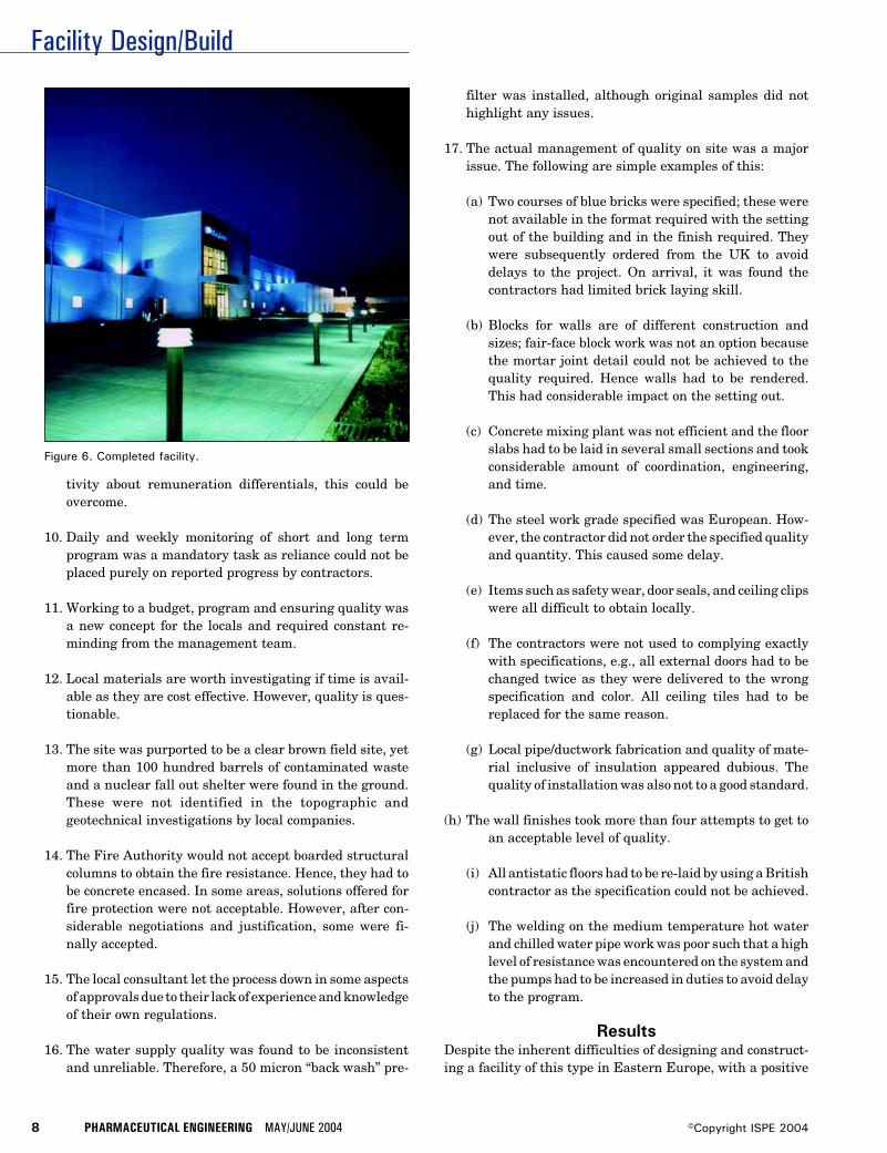
Facility Design/Build
8 PHARMACEUTICAL ENGINEERING MAY/JUNE 2004 ©Copyright ISPE 2004
Figure 6. Completed facility.
tivity about remuneration differentials, this could beovercome.
10. Daily and weekly monitoring of short and long termprogram was a mandatory task as reliance could not beplaced purely on reported progress by contractors.
11. Working to a budget, program and ensuring quality wasa new concept for the locals and required constant re-minding from the management team.
12. Local materials are worth investigating if time is avail-able as they are cost effective. However, quality is ques-tionable.
13. The site was purported to be a clear brown field site, yetmore than 100 hundred barrels of contaminated wasteand a nuclear fall out shelter were found in the ground.These were not identified in the topographic andgeotechnical investigations by local companies.
14. The Fire Authority would not accept boarded structuralcolumns to obtain the fire resistance. Hence, they had tobe concrete encased. In some areas, solutions offered forfire protection were not acceptable. However, after con-siderable negotiations and justification, some were fi-nally accepted.
15. The local consultant let the process down in some aspectsof approvals due to their lack of experience and knowledgeof their own regulations.
16. The water supply quality was found to be inconsistentand unreliable. Therefore, a 50 micron “back wash” pre-
filter was installed, although original samples did nothighlight any issues.
17. The actual management of quality on site was a majorissue. The following are simple examples of this:
(a) Two courses of blue bricks were specified; these werenot available in the format required with the settingout of the building and in the finish required. Theywere subsequently ordered from the UK to avoiddelays to the project. On arrival, it was found thecontractors had limited brick laying skill.
(b) Blocks for walls are of different construction andsizes; fair-face block work was not an option becausethe mortar joint detail could not be achieved to thequality required. Hence walls had to be rendered.This had considerable impact on the setting out.
(c) Concrete mixing plant was not efficient and the floorslabs had to be laid in several small sections and tookconsiderable amount of coordination, engineering,and time.
(d) The steel work grade specified was European. How-ever, the contractor did not order the specified qualityand quantity. This caused some delay.
(e) Items such as safety wear, door seals, and ceiling clipswere all difficult to obtain locally.
(f) The contractors were not used to complying exactlywith specifications, e.g., all external doors had to bechanged twice as they were delivered to the wrongspecification and color. All ceiling tiles had to bereplaced for the same reason.
(g) Local pipe/ductwork fabrication and quality of mate-rial inclusive of insulation appeared dubious. Thequality of installation was also not to a good standard.
(h) The wall finishes took more than four attempts to get toan acceptable level of quality.
(i) All antistatic floors had to be re-laid by using a Britishcontractor as the specification could not be achieved.
(j) The welding on the medium temperature hot waterand chilled water pipe work was poor such that a highlevel of resistance was encountered on the system andthe pumps had to be increased in duties to avoid delayto the program.
ResultsDespite the inherent difficulties of designing and construct-ing a facility of this type in Eastern Europe, with a positive
Facility Design/Build
MAY/JUNE 2004 PHARMACEUTICAL ENGINEERING 9©Copyright ISPE 2004
attitude by the team, the problems were overcome to producean excellent facility.
Speed was a key factor and the critical time schedules metare seen in Figure 4. The overall budget cost was not ex-ceeded. Savings were made on local contracts such as groundworks, civils, steelwork, cladding, and finishes. There was anoverspending on process equipment such as granulation,tablet machines, blender, blister lines, pure water plant etc.Site supervision was overspent, primarily because of theextensive checks required.
The overall cost of completion was 7.5% below the agreedbudget, i.e., just more than $1 million under the $15 millionbudget. This was achieved by preparing good quality engi-neering documentation for tendering, pre-selection of compa-nies to be invited to tender, post tender interviews to ensurecompliance – technically, financially, and availability ofresources; good negotiating and buying skills on the packagesand a pro-active client to allow the UK company to effectivelydesign and assist them in management of the project, yetmaking themselves available to respond efficiently and makedecisions when required.
The quality goals were in most cases accomplished andhave met cGMP standards.
However, anyone considering a similar project in thefuture must employ more on-site dedicated supervisors tomonitor day to day installation and material quality.
The granulation/fluid bed dryer suite and external view ofthe facility are shown in Figures 5 and 6 respectively todemonstrate the quality achieved.
The facility has obtained its operating license from theBulgarian Drug Agency and is in the process of being pre-pared for an MCA inspection for products made for theEuropean market.
Safety standards imposed on site were in accordance withUK’s Construction Design and Management regulations.These were stipulated as part of the appointment of contrac-tors. In reality, they were difficult to impose as the correctform of Personal Protective Equipment was not readily avail-able and there was no motivation by subcontractors to obtainthem. However, the safety record on site was better than theaverage UK site.
Highlights of the Project• first cGMP compliant facility design in Bulgaria• first facility to be inspected by the MCA in Bulgaria• first substantial pharmaceutical project in Bulgaria over
the last 12 to 15 years• facility complete within 12 months from starting on site• facility ready for manufacturing within six months of
completion of construction
• first facility validated to EU standards in Bulgaria• probably the best pharmaceutical facility in Bulgaria if
not in Eastern Europe• quality of the finished project was generally very good and
comparable to the best in the UK• completed project cost $1 million below the $15 budget• several cultural problems overcome successfully• several political problems with approvals addressed suc-
cessfully• facility - available for PQ/production 18 months from the
first operation on site• formal opening ceremony achieved 12 months from the
first ground breaking• benchmark set for future pharmaceutical facilities in
Eastern Europe• pro-activeness by the operating company gave the UK
company better control and management of the overallproject
• the operating company managed very professionally• safety statistics on site better than a comparable project in
UK
AcknowledgementsThanks are due for the cooperation and support received fromthe operating company in particular Mr. Jon Bergsson –Chief Operations Officer during the preparation of this ar-ticle.
About the AuthorPrakash Davda is the Deputy ManagingDirector of The Austin Company of UK Lim-ited based in London, UK. Davda has morethan 20 years of experience in the design andconstruction of high tech facilities through-out the UK. Throughout the last 10 years, hehas been heavily involved in project activi-ties for laboratories, pilot plants, production
units, and warehousing for the pharmaceutical industrywithin the UK. He held the post of Principle in Charge for theBulgarian project and managed the design, construction,commissioning, validation, and start-up teams. Davda is amember of the Institute of Electrical Engineers, The Char-tered Institution of Building Services Engineers, and ob-tained his Masters in economics and management from TheBartlett School of Graduate (University College London) in1995. He can be contacted by tel: +44-208-371-9000 or byemail: [email protected].
The Austin Company of UK Limited, 35 Ballards Lane,Finchley, London, N3 1XW, United Kingdom.
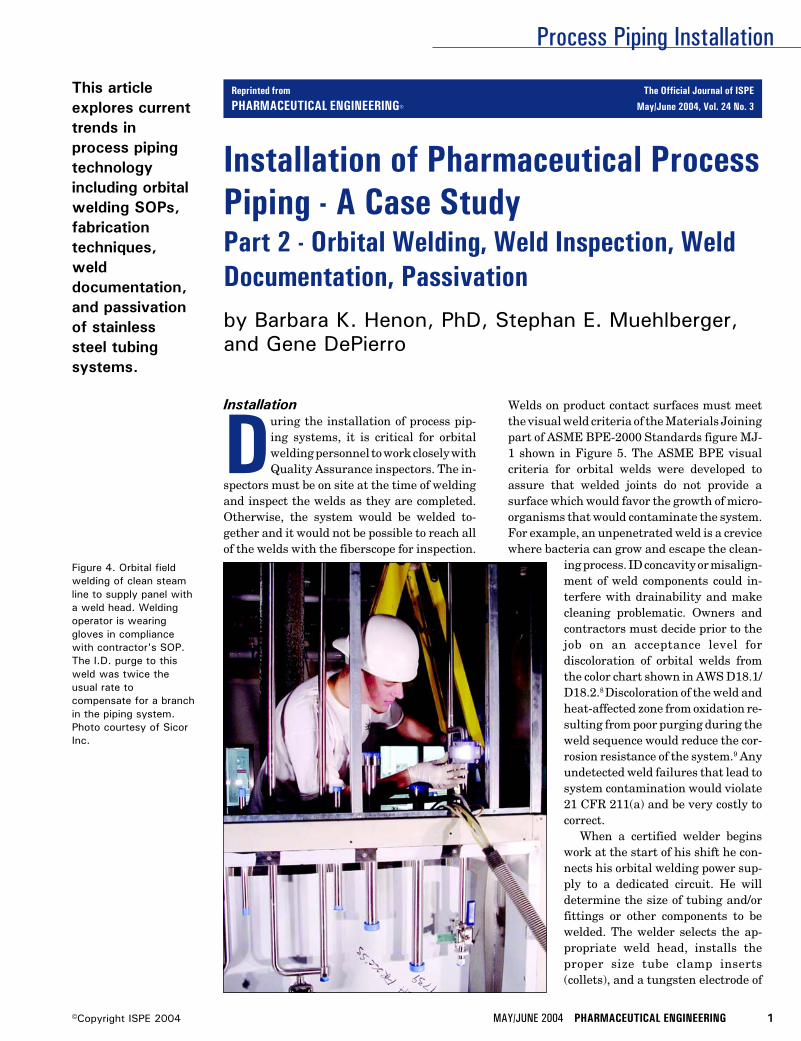
Process Piping Installation
MAY/JUNE 2004 PHARMACEUTICAL ENGINEERING 1©Copyright ISPE 2004
This articleexplores currenttrends inprocess pipingtechnologyincluding orbitalwelding SOPs,fabricationtechniques,welddocumentation,and passivationof stainlesssteel tubingsystems.
Installation
During the installation of process pip-ing systems, it is critical for orbitalwelding personnel to work closely withQuality Assurance inspectors. The in-
spectors must be on site at the time of weldingand inspect the welds as they are completed.Otherwise, the system would be welded to-gether and it would not be possible to reach allof the welds with the fiberscope for inspection.
Installation of Pharmaceutical ProcessPiping - A Case StudyPart 2 - Orbital Welding, Weld Inspection, WeldDocumentation, Passivationby Barbara K. Henon, PhD, Stephan E. Muehlberger,and Gene DePierro
Figure 4. Orbital fieldwelding of clean steamline to supply panel witha weld head. Weldingoperator is wearinggloves in compliancewith contractor's SOP.The I.D. purge to thisweld was twice theusual rate tocompensate for a branchin the piping system.Photo courtesy of SicorInc.
Welds on product contact surfaces must meetthe visual weld criteria of the Materials Joiningpart of ASME BPE-2000 Standards figure MJ-1 shown in Figure 5. The ASME BPE visualcriteria for orbital welds were developed toassure that welded joints do not provide asurface which would favor the growth of micro-organisms that would contaminate the system.For example, an unpenetrated weld is a crevicewhere bacteria can grow and escape the clean-
ing process. ID concavity or misalign-ment of weld components could in-terfere with drainability and makecleaning problematic. Owners andcontractors must decide prior to thejob on an acceptance level fordiscoloration of orbital welds fromthe color chart shown in AWS D18.1/D18.2.8 Discoloration of the weld andheat-affected zone from oxidation re-sulting from poor purging during theweld sequence would reduce the cor-rosion resistance of the system.9 Anyundetected weld failures that lead tosystem contamination would violate21 CFR 211(a) and be very costly tocorrect.
When a certified welder beginswork at the start of his shift he con-nects his orbital welding power sup-ply to a dedicated circuit. He willdetermine the size of tubing and/orfittings or other components to bewelded. The welder selects the ap-propriate weld head, installs theproper size tube clamp inserts(collets), and a tungsten electrode of
Reprinted from The Official Journal of ISPE
PHARMACEUTICAL ENGINEERING® May/June 2004, Vol. 24 No. 3
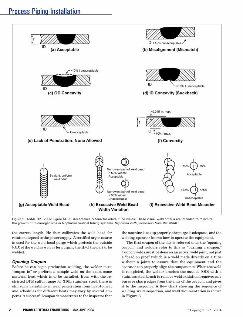
Process Piping Installation
2 PHARMACEUTICAL ENGINEERING MAY/JUNE 2004 ©Copyright ISPE 2004
the correct length. He then calibrates the weld head forrotational speed to the power supply. A certified argon sourceis used for the weld head purge which protects the outside(OD) of the weld as well as for purging the ID of the part to bewelded.
Opening CouponBefore he can begin production welding, the welder must“coupon in” or perform a sample weld on the exact samematerial heat which is to be installed. Even with the re-stricted BPE sulfur range for 316L stainless steel, there isstill some variability in weld penetration from heat-to-heatand schedules for different heats may vary by several am-peres. A successful coupon demonstrates to the inspector that
the machine is set up properly, the purge is adequate, and thewelding operator knows how to operate the equipment.
The first coupon of the day is referred to as the “openingcoupon” and welders refer to this as “burning a coupon.”Coupon welds must be done on an actual weld joint, not justa “bead on pipe” (which is a weld made directly on a tubewithout a joint) to assure that the equipment and theoperator can properly align the components. When the weldis completed, the welder brushes the outside (OD) with astainless steel brush to remove weld oxidation, removes anyburrs or sharp edges from the ends of the coupon, and givesit to the inspector. A flow chart showing the sequence ofwelding, weld inspection, and weld documentation is shownin Figure 6.
Figure 5. ASME BPE-2002 Figure MJ-1. Acceptance criteria for orbital tube welds. These visual weld criteria are intended to minimizethe growth of microorganisms in biopharmaceutical tubing systems. Reprinted with permission from the ASME.
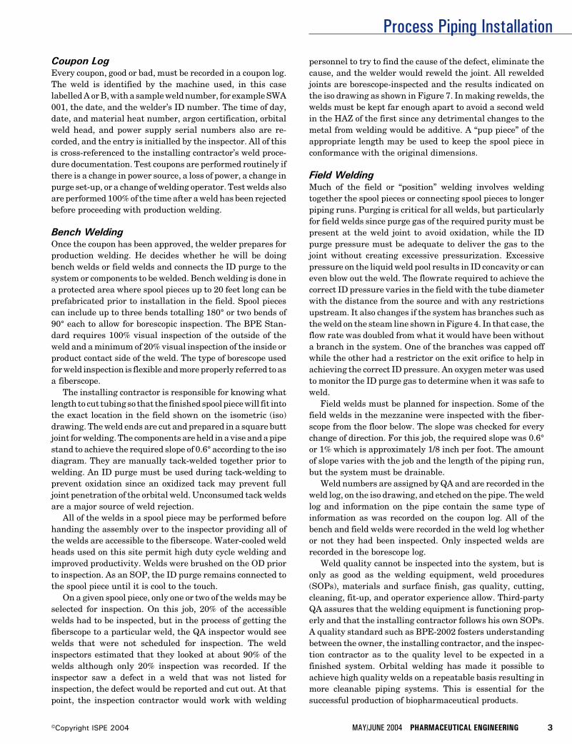
Process Piping Installation
MAY/JUNE 2004 PHARMACEUTICAL ENGINEERING 3©Copyright ISPE 2004
Coupon LogEvery coupon, good or bad, must be recorded in a coupon log.The weld is identified by the machine used, in this caselabelled A or B, with a sample weld number, for example SWA001, the date, and the welder’s ID number. The time of day,date, and material heat number, argon certification, orbitalweld head, and power supply serial numbers also are re-corded, and the entry is initialled by the inspector. All of thisis cross-referenced to the installing contractor’s weld proce-dure documentation. Test coupons are performed routinely ifthere is a change in power source, a loss of power, a change inpurge set-up, or a change of welding operator. Test welds alsoare performed 100% of the time after a weld has been rejectedbefore proceeding with production welding.
Bench WeldingOnce the coupon has been approved, the welder prepares forproduction welding. He decides whether he will be doingbench welds or field welds and connects the ID purge to thesystem or components to be welded. Bench welding is done ina protected area where spool pieces up to 20 feet long can beprefabricated prior to installation in the field. Spool piecescan include up to three bends totalling 180° or two bends of90° each to allow for borescopic inspection. The BPE Stan-dard requires 100% visual inspection of the outside of theweld and a minimum of 20% visual inspection of the inside orproduct contact side of the weld. The type of borescope usedfor weld inspection is flexible and more properly referred to asa fiberscope.
The installing contractor is responsible for knowing whatlength to cut tubing so that the finished spool piece will fit intothe exact location in the field shown on the isometric (iso)drawing. The weld ends are cut and prepared in a square buttjoint for welding. The components are held in a vise and a pipestand to achieve the required slope of 0.6° according to the isodiagram. They are manually tack-welded together prior towelding. An ID purge must be used during tack-welding toprevent oxidation since an oxidized tack may prevent fulljoint penetration of the orbital weld. Unconsumed tack weldsare a major source of weld rejection.
All of the welds in a spool piece may be performed beforehanding the assembly over to the inspector providing all ofthe welds are accessible to the fiberscope. Water-cooled weldheads used on this site permit high duty cycle welding andimproved productivity. Welds were brushed on the OD priorto inspection. As an SOP, the ID purge remains connected tothe spool piece until it is cool to the touch.
On a given spool piece, only one or two of the welds may beselected for inspection. On this job, 20% of the accessiblewelds had to be inspected, but in the process of getting thefiberscope to a particular weld, the QA inspector would seewelds that were not scheduled for inspection. The weldinspectors estimated that they looked at about 90% of thewelds although only 20% inspection was recorded. If theinspector saw a defect in a weld that was not listed forinspection, the defect would be reported and cut out. At thatpoint, the inspection contractor would work with welding
personnel to try to find the cause of the defect, eliminate thecause, and the welder would reweld the joint. All reweldedjoints are borescope-inspected and the results indicated onthe iso drawing as shown in Figure 7. In making rewelds, thewelds must be kept far enough apart to avoid a second weldin the HAZ of the first since any detrimental changes to themetal from welding would be additive. A “pup piece” of theappropriate length may be used to keep the spool piece inconformance with the original dimensions.
Field WeldingMuch of the field or “position” welding involves weldingtogether the spool pieces or connecting spool pieces to longerpiping runs. Purging is critical for all welds, but particularlyfor field welds since purge gas of the required purity must bepresent at the weld joint to avoid oxidation, while the IDpurge pressure must be adequate to deliver the gas to thejoint without creating excessive pressurization. Excessivepressure on the liquid weld pool results in ID concavity or caneven blow out the weld. The flowrate required to achieve thecorrect ID pressure varies in the field with the tube diameterwith the distance from the source and with any restrictionsupstream. It also changes if the system has branches such asthe weld on the steam line shown in Figure 4. In that case, theflow rate was doubled from what it would have been withouta branch in the system. One of the branches was capped offwhile the other had a restrictor on the exit orifice to help inachieving the correct ID pressure. An oxygen meter was usedto monitor the ID purge gas to determine when it was safe toweld.
Field welds must be planned for inspection. Some of thefield welds in the mezzanine were inspected with the fiber-scope from the floor below. The slope was checked for everychange of direction. For this job, the required slope was 0.6°or 1% which is approximately 1/8 inch per foot. The amountof slope varies with the job and the length of the piping run,but the system must be drainable.
Weld numbers are assigned by QA and are recorded in theweld log, on the iso drawing, and etched on the pipe. The weldlog and information on the pipe contain the same type ofinformation as was recorded on the coupon log. All of thebench and field welds were recorded in the weld log whetheror not they had been inspected. Only inspected welds arerecorded in the borescope log.
Weld quality cannot be inspected into the system, but isonly as good as the welding equipment, weld procedures(SOPs), materials and surface finish, gas quality, cutting,cleaning, fit-up, and operator experience allow. Third-partyQA assures that the welding equipment is functioning prop-erly and that the installing contractor follows his own SOPs.A quality standard such as BPE-2002 fosters understandingbetween the owner, the installing contractor, and the inspec-tion contractor as to the quality level to be expected in afinished system. Orbital welding has made it possible toachieve high quality welds on a repeatable basis resulting inmore cleanable piping systems. This is essential for thesuccessful production of biopharmaceutical products.
Process Piping Installation
4 PHARMACEUTICAL ENGINEERING MAY/JUNE 2004 ©Copyright ISPE 2004
Orbital Welding of SkidsOrbital welding is used extensively in the manufacture ofequipment skids such as CIP skids or skids with stills forproducing WFI. A considerable amount of stainless steeltubing is used to connect the various components on theskids. The skids are assembled by orbital welding at the
Figure 6. Flow chart for orbital welding/inspection/documentation of stainless steel welds.
vendor and brought to the pharmaceutical plant for installa-tion. All of these welds and the field welds done wheninstalling the skid on site must meet the same welding QArequirements. Welds done during skid manufacture are in-spected at the vendor.
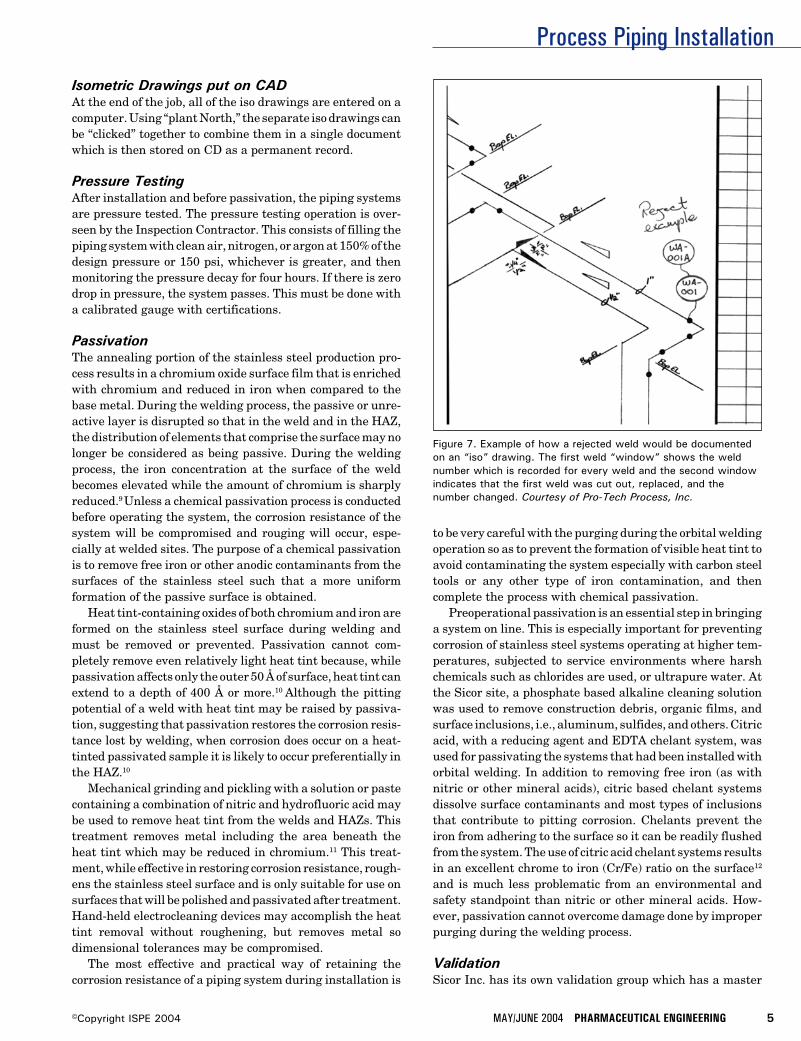
Process Piping Installation
MAY/JUNE 2004 PHARMACEUTICAL ENGINEERING 5©Copyright ISPE 2004
Figure 7. Example of how a rejected weld would be documentedon an “iso” drawing. The first weld “window” shows the weldnumber which is recorded for every weld and the second windowindicates that the first weld was cut out, replaced, and thenumber changed. Courtesy of Pro-Tech Process, Inc.
Isometric Drawings put on CADAt the end of the job, all of the iso drawings are entered on acomputer. Using “plant North,” the separate iso drawings canbe “clicked” together to combine them in a single documentwhich is then stored on CD as a permanent record.
Pressure TestingAfter installation and before passivation, the piping systemsare pressure tested. The pressure testing operation is over-seen by the Inspection Contractor. This consists of filling thepiping system with clean air, nitrogen, or argon at 150% of thedesign pressure or 150 psi, whichever is greater, and thenmonitoring the pressure decay for four hours. If there is zerodrop in pressure, the system passes. This must be done witha calibrated gauge with certifications.
PassivationThe annealing portion of the stainless steel production pro-cess results in a chromium oxide surface film that is enrichedwith chromium and reduced in iron when compared to thebase metal. During the welding process, the passive or unre-active layer is disrupted so that in the weld and in the HAZ,the distribution of elements that comprise the surface may nolonger be considered as being passive. During the weldingprocess, the iron concentration at the surface of the weldbecomes elevated while the amount of chromium is sharplyreduced.9 Unless a chemical passivation process is conductedbefore operating the system, the corrosion resistance of thesystem will be compromised and rouging will occur, espe-cially at welded sites. The purpose of a chemical passivationis to remove free iron or other anodic contaminants from thesurfaces of the stainless steel such that a more uniformformation of the passive surface is obtained.
Heat tint-containing oxides of both chromium and iron areformed on the stainless steel surface during welding andmust be removed or prevented. Passivation cannot com-pletely remove even relatively light heat tint because, whilepassivation affects only the outer 50 Å of surface, heat tint canextend to a depth of 400 Å or more.10 Although the pittingpotential of a weld with heat tint may be raised by passiva-tion, suggesting that passivation restores the corrosion resis-tance lost by welding, when corrosion does occur on a heat-tinted passivated sample it is likely to occur preferentially inthe HAZ.10
Mechanical grinding and pickling with a solution or pastecontaining a combination of nitric and hydrofluoric acid maybe used to remove heat tint from the welds and HAZs. Thistreatment removes metal including the area beneath theheat tint which may be reduced in chromium.11 This treat-ment, while effective in restoring corrosion resistance, rough-ens the stainless steel surface and is only suitable for use onsurfaces that will be polished and passivated after treatment.Hand-held electrocleaning devices may accomplish the heattint removal without roughening, but removes metal sodimensional tolerances may be compromised.
The most effective and practical way of retaining thecorrosion resistance of a piping system during installation is
to be very careful with the purging during the orbital weldingoperation so as to prevent the formation of visible heat tint toavoid contaminating the system especially with carbon steeltools or any other type of iron contamination, and thencomplete the process with chemical passivation.
Preoperational passivation is an essential step in bringinga system on line. This is especially important for preventingcorrosion of stainless steel systems operating at higher tem-peratures, subjected to service environments where harshchemicals such as chlorides are used, or ultrapure water. Atthe Sicor site, a phosphate based alkaline cleaning solutionwas used to remove construction debris, organic films, andsurface inclusions, i.e., aluminum, sulfides, and others. Citricacid, with a reducing agent and EDTA chelant system, wasused for passivating the systems that had been installed withorbital welding. In addition to removing free iron (as withnitric or other mineral acids), citric based chelant systemsdissolve surface contaminants and most types of inclusionsthat contribute to pitting corrosion. Chelants prevent theiron from adhering to the surface so it can be readily flushedfrom the system. The use of citric acid chelant systems resultsin an excellent chrome to iron (Cr/Fe) ratio on the surface12
and is much less problematic from an environmental andsafety standpoint than nitric or other mineral acids. How-ever, passivation cannot overcome damage done by improperpurging during the welding process.
ValidationSicor Inc. has its own validation group which has a master
Process Piping Installation
6 PHARMACEUTICAL ENGINEERING MAY/JUNE 2004 ©Copyright ISPE 2004
plan for validation. There is a separate validation protocol foreach system such as WFI, CIP, clean steam, etc. The valida-tion group does a spot check during the installation and theyhire third-party QA who works directly for Sicor. The owneris responsible for working with the FDA to assure them thateverything is being done according to current Good Manufac-turing Practices (cGMP) and that they have the documentationto prove it.
Risk of ChangeWhen the facility is done, the user starts using it. Once hebegins using the system, an operator may find a better way todo his job. This may involve moving piping. Such changes aretypical. In the four to five years that it takes to make thevision a reality, the requirements for the facility may change.FDA approval for the drug for which the system at Sicor wasbuilt is expected in 2004, but there is always the risk that itwon’t be approved; then the facility would have to be modifiedto produce a different drug. They may need to switch a systemfor the production of a new drug or, if the current drugbecomes a big seller, they may need to increase the systemcapacity to make larger quantities. This might require anadjustment of the flow rate of a water system or a change inthe operating temperature. Unexpected changes put a strainon all utilities, water, and infrastructure. Steve Muehlbergerlikes to make his systems “robust” so they can change direc-tions as demands on the system evolve.
References8. AWS D18.1/D18.2, Specification for welding of austenitic
stainless steel tube and pipe systems in sanitary (hy-gienic) applications American Welding Society550 N.W.Le Jeune Road, Miami, FL 33126.
9. Balmer, Kenneth B., “Auger Surface Line Scan to Evalu-ate Element Segregation in and Chelant Passivation of a316L Weld,” Pharmaceutical Engineering, Vol. 15, No. 3,1995, pp. 66-70.
10. Grant, Arnie, Henon, Barbara, K., and Mansfeld, Florian,“Effects of Purge Gas Purity and Chelant Passivation onthe Corrosion Resistance of Orbitally Welded 316L Stain-less Steel - Part I,” Pharmaceutical Engineering, Vol. 17,No.1, 1997, pp. 46-60, Part II, Vol. 17, No. 2, 1997.
11. Tuthill, Arthur, “Stainless Steel: Surface Cleanliness,”Pharmaceutical Engineering, November/December 1994,Vol. 14, No. 6.
12. Roll, Daryl, Current Methodologies and Chemistries Uti-lized in Effective Passivation Procedures. Presented atINTERPHEX Pharmaceutical Conference, PennsylvaniaConference Center, Philadelphia, PA, April 15-17, 1997.
AcknowledgementsThe authors would like to thank Joshua Lohnes and MichaelAubin of Purity Systems, Inc. for sharing their expertise onQuality Assurance and Daryl Roll and Steve Biggers of AstroPak for sharing their expertise on Passivation.
About the AuthorsBarbara K. Henon, PhD, Manager of Tech-nical Publications at Arc Machines, Inc., hasbeen employed by Arc Machines since 1984.During this time, she has been an instructorof orbital tube welding and has written ar-ticles on customer applications in thebiopharmaceutical, semiconductor, offshore,and other industries which share a need for
high-quality welds. She also writes Operator Training Manu-als for the company. Dr. Henon is Vice Chair of the MainCommittee of the ASME Bioprocess Equipment Standardand has been a member of the BPE Materials JoiningSubcommittee since 1989. She also serves on several AWSand SEMI Standards writing groups. She can be contacted bytel: 1-818/896-9556 or by e-mail: [email protected].
Arc Machines, Inc., 10500 Orbital Way, Pacoima, CA91331.
Stephan E. Muehlberger is a Senior Man-ager Project and Process Engineer at SicorInc. He has been with SICOR since 1995. Hehas been responsible for the integration ofsterile filling lines, inspection/packaging ex-pansions, process compounding suites, facil-ity infrastructure expansions (WFI, cleansteam, plant utilities). The current project is
a $19 million facility expansion incorporating two sterilefilling lines, two compounding lines, two compounding suites,and a component preparation area. His previous experiencewas as an engineer with a company specializing in plasmacutting. He can be contacted by tel: 1-949/455-4791 or by e-mail: [email protected].
Sicor Pharmaceuticals, Inc., 19 Hughes St., Irvine, CA92618.
Gene DePierro, President of Pro-Tech Pro-cess, Inc., started Pro-Tech in 1997 aftermany years of process piping experience. Heworked for Fluor Daniel and Brown andRoot. Pro-Tech is the largest “open shop”process piping contractor in Southern Cali-fornia. Pro-Tech specializes in process pipingand cGMP plumbing for pharmaceutical and
biotech installations. He can be contacted by tel: 1-858/495-0573 or by e-mail: [email protected].
Pro-Tech Process, Inc., 9484 Chesapeake Dr., Suite 806,San Diego, CA 92123.
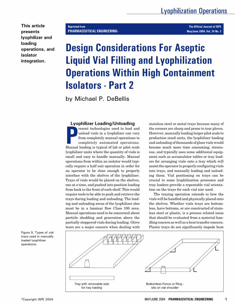
Lyophilization Operations
MAY/JUNE 2004 PHARMACEUTICAL ENGINEERING 1©Copyright ISPE 2004
Design Considerations For AsepticLiquid Vial Filling and LyophilizationOperations Within High ContainmentIsolators - Part 2
This articlepresentslyophilizer andloadingoperations, andisolatorintegration.
by Michael P. DeBellis
Figure 9. Types of vialtrays used in manuallyloaded lyophilizeroperations.
Lyophilizer Loading/Unloading
Present technologies used to load andunload vials in a lyophilizer can varyfrom completely manual operations tocompletely automated operations.
Manual loading is typical of lab or pilot scalelyophilizer units where the quantity of vials issmall and easy to handle manually. Manualoperations from within an isolator would typi-cally require a half suit operation in order foran operator to be close enough to properlyinterface with the shelves of the lyophilizer.Trays of vials would be placed on the shelves,one at a time, and pushed into position loadingfrom back to the front of each shelf. This wouldrequire tools to be able to push and retrieve thetrays during loading and unloading. The load-ing and unloading areas of the lyophilizer alsomust be in a laminar flow Class 100 area.Manual operations need to be concerned aboutparticle shedding and generation above thepartially stoppered vials during loading. Glovetears are a major concern when dealing with
stainless steel or metal trays because many ofthe corners are sharp and prone to tear gloves.However, manually loading larger pilot scale toproduction sized units, the lyophilizer loadingand unloading of thousands of glass vials wouldbecome much more time consuming, strenu-ous, and typically uses some additional equip-ment such as accumulator tables or tray load-ers for arranging vials onto a tray which willassist the operator in properly configuring vialsinto trays, and manually loading and unload-ing them. Vial positioning on trays can becrucial to some lyophilization processes andtray loaders provide a repeatable vial orienta-tion on the trays for each vial size used.
The traying operation extends to how thevials will be handled and physically placed ontothe shelves. Whether vials trays are bottom-less, have bottoms, or are constructed of stain-less steel or plastic, is a process related issuethat should be evaluated from a material han-dling concern as well as a heat transfer concern.Plastic trays do not significantly impede heat
Reprinted from The Official Journal of ISPE
PHARMACEUTICAL ENGINEERING® May/June 2004, Vol. 24 No. 3
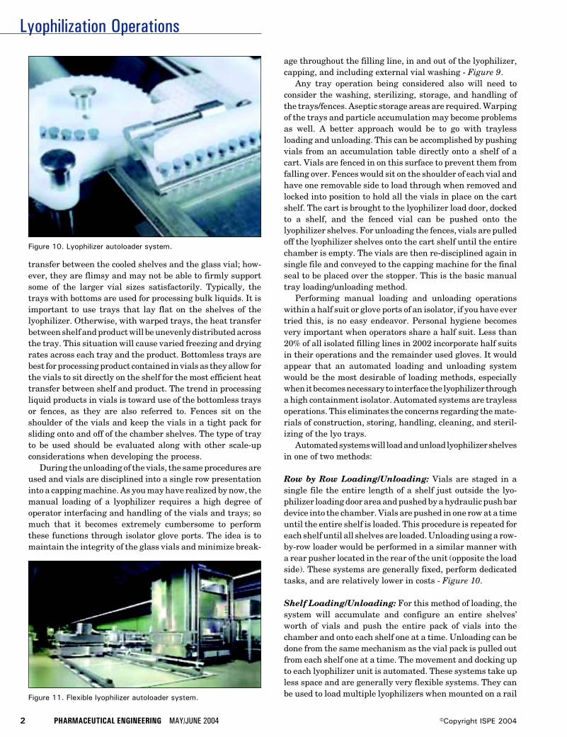
Lyophilization Operations
2 PHARMACEUTICAL ENGINEERING MAY/JUNE 2004 ©Copyright ISPE 2004
Figure 11. Flexible lyophilizer autoloader system.
transfer between the cooled shelves and the glass vial; how-ever, they are flimsy and may not be able to firmly supportsome of the larger vial sizes satisfactorily. Typically, thetrays with bottoms are used for processing bulk liquids. It isimportant to use trays that lay flat on the shelves of thelyophilizer. Otherwise, with warped trays, the heat transferbetween shelf and product will be unevenly distributed acrossthe tray. This situation will cause varied freezing and dryingrates across each tray and the product. Bottomless trays arebest for processing product contained in vials as they allow forthe vials to sit directly on the shelf for the most efficient heattransfer between shelf and product. The trend in processingliquid products in vials is toward use of the bottomless traysor fences, as they are also referred to. Fences sit on theshoulder of the vials and keep the vials in a tight pack forsliding onto and off of the chamber shelves. The type of trayto be used should be evaluated along with other scale-upconsiderations when developing the process.
During the unloading of the vials, the same procedures areused and vials are disciplined into a single row presentationinto a capping machine. As you may have realized by now, themanual loading of a lyophilizer requires a high degree ofoperator interfacing and handling of the vials and trays; somuch that it becomes extremely cumbersome to performthese functions through isolator glove ports. The idea is tomaintain the integrity of the glass vials and minimize break-
age throughout the filling line, in and out of the lyophilizer,capping, and including external vial washing - Figure 9.
Any tray operation being considered also will need toconsider the washing, sterilizing, storage, and handling ofthe trays/fences. Aseptic storage areas are required. Warpingof the trays and particle accumulation may become problemsas well. A better approach would be to go with traylessloading and unloading. This can be accomplished by pushingvials from an accumulation table directly onto a shelf of acart. Vials are fenced in on this surface to prevent them fromfalling over. Fences would sit on the shoulder of each vial andhave one removable side to load through when removed andlocked into position to hold all the vials in place on the cartshelf. The cart is brought to the lyophilizer load door, dockedto a shelf, and the fenced vial can be pushed onto thelyophilizer shelves. For unloading the fences, vials are pulledoff the lyophilizer shelves onto the cart shelf until the entirechamber is empty. The vials are then re-disciplined again insingle file and conveyed to the capping machine for the finalseal to be placed over the stopper. This is the basic manualtray loading/unloading method.
Performing manual loading and unloading operationswithin a half suit or glove ports of an isolator, if you have evertried this, is no easy endeavor. Personal hygiene becomesvery important when operators share a half suit. Less than20% of all isolated filling lines in 2002 incorporate half suitsin their operations and the remainder used gloves. It wouldappear that an automated loading and unloading systemwould be the most desirable of loading methods, especiallywhen it becomes necessary to interface the lyophilizer througha high containment isolator. Automated systems are traylessoperations. This eliminates the concerns regarding the mate-rials of construction, storing, handling, cleaning, and steril-izing of the lyo trays.
Automated systems will load and unload lyophilizer shelvesin one of two methods:
Row by Row Loading/Unloading: Vials are staged in asingle file the entire length of a shelf just outside the lyo-philizer loading door area and pushed by a hydraulic push bardevice into the chamber. Vials are pushed in one row at a timeuntil the entire shelf is loaded. This procedure is repeated foreach shelf until all shelves are loaded. Unloading using a row-by-row loader would be performed in a similar manner witha rear pusher located in the rear of the unit (opposite the loadside). These systems are generally fixed, perform dedicatedtasks, and are relatively lower in costs - Figure 10.
Shelf Loading/Unloading: For this method of loading, thesystem will accumulate and configure an entire shelves’worth of vials and push the entire pack of vials into thechamber and onto each shelf one at a time. Unloading can bedone from the same mechanism as the vial pack is pulled outfrom each shelf one at a time. The movement and docking upto each lyophilizer unit is automated. These systems take upless space and are generally very flexible systems. They canbe used to load multiple lyophilizers when mounted on a rail
Figure 10. Lyophilizer autoloader system.
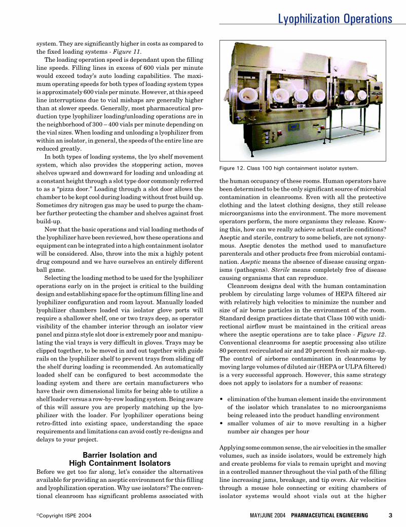
Lyophilization Operations
MAY/JUNE 2004 PHARMACEUTICAL ENGINEERING 3©Copyright ISPE 2004
system. They are significantly higher in costs as compared tothe fixed loading systems - Figure 11.
The loading operation speed is dependant upon the fillingline speeds. Filling lines in excess of 600 vials per minutewould exceed today’s auto loading capabilities. The maxi-mum operating speeds for both types of loading system typesis approximately 600 vials per minute. However, at this speedline interruptions due to vial mishaps are generally higherthan at slower speeds. Generally, most pharmaceutical pro-duction type lyophilizer loading/unloading operations are inthe neighborhood of 300 – 400 vials per minute depending onthe vial sizes. When loading and unloading a lyophilizer fromwithin an isolator, in general, the speeds of the entire line arereduced greatly.
In both types of loading systems, the lyo shelf movementsystem, which also provides the stoppering action, movesshelves upward and downward for loading and unloading ata constant height through a slot type door commonly referredto as a “pizza door.” Loading through a slot door allows thechamber to be kept cool during loading without frost build up.Sometimes dry nitrogen gas may be used to purge the cham-ber further protecting the chamber and shelves against frostbuild-up.
Now that the basic operations and vial loading methods ofthe lyophilizer have been reviewed, how these operations andequipment can be integrated into a high containment isolatorwill be considered. Also, throw into the mix a highly potentdrug compound and we have ourselves an entirely differentball game.
Selecting the loading method to be used for the lyophilizeroperations early on in the project is critical to the buildingdesign and establishing space for the optimum filling line andlyophilizer configuration and room layout. Manually loadedlyophilizer chambers loaded via isolator glove ports willrequire a shallower shelf, one or two trays deep, as operatorvisibility of the chamber interior through an isolator viewpanel and pizza style slot door is extremely poor and manipu-lating the vial trays is very difficult in gloves. Trays may beclipped together, to be moved in and out together with guiderails on the lyophilizer shelf to prevent trays from sliding offthe shelf during loading is recommended. An automaticallyloaded shelf can be configured to best accommodate theloading system and there are certain manufacturers whohave their own dimensional limits for being able to utilize ashelf loader versus a row-by-row loading system. Being awareof this will assure you are properly matching up the lyo-philizer with the loader. For lyophilizer operations beingretro-fitted into existing space, understanding the spacerequirements and limitations can avoid costly re-designs anddelays to your project.
Barrier Isolation andHigh Containment Isolators
Before we get too far along, let’s consider the alternativesavailable for providing an aseptic environment for this fillingand lyophilization operation. Why use isolators? The conven-tional cleanroom has significant problems associated with
the human occupancy of these rooms. Human operators havebeen determined to be the only significant source of microbialcontamination in cleanrooms. Even with all the protectiveclothing and the latest clothing designs, they still releasemicroorganisms into the environment. The more movementoperators perform, the more organisms they release. Know-ing this, how can we really achieve actual sterile conditions?Aseptic and sterile, contrary to some beliefs, are not synony-mous. Aseptic denotes the method used to manufactureparenterals and other products free from microbial contami-nation. Aseptic means the absence of disease causing organ-isms (pathogens). Sterile means completely free of diseasecausing organisms that can reproduce.
Cleanroom designs deal with the human contaminationproblem by circulating large volumes of HEPA filtered airwith relatively high velocities to minimize the number andsize of air borne particles in the environment of the room.Standard design practices dictate that Class 100 with unidi-rectional airflow must be maintained in the critical areaswhere the aseptic operations are to take place - Figure 12.Conventional cleanrooms for aseptic processing also utilize80 percent recirculated air and 20 percent fresh air make-up.The control of airborne contamination in cleanrooms bymoving large volumes of diluted air (HEPA or ULPA filtered)is a very successful approach. However, this same strategydoes not apply to isolators for a number of reasons:
• elimination of the human element inside the environmentof the isolator which translates to no microorganismsbeing released into the product handling environment
• smaller volumes of air to move resulting in a highernumber air changes per hour
Applying some common sense, the air velocities in the smallervolumes, such as inside isolators, would be extremely highand create problems for vials to remain upright and movingin a controlled manner throughout the vial path of the fillingline increasing jams, breakage, and tip overs. Air velocitiesthrough a mouse hole connecting or exiting chambers ofisolator systems would shoot vials out at the higher
Figure 12. Class 100 high containment isolator system.
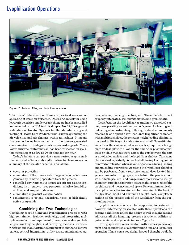
Lyophilization Operations
4 PHARMACEUTICAL ENGINEERING MAY/JUNE 2004 ©Copyright ISPE 2004
“cleanroom” velocities. So, there are practical reasons foroperating at lower air velocities. Operating an isolator usinglower air velocities and lower air changers has been studiedand reported in the PDA technical report No. 34, “Design andValidation of Isolator Systems for the Manufacturing andTesting of Health Care Product.” This is key in optimizing theair velocities and air changes within an isolator. It meansthat we no longer have to deal with the human generatedcontamination to the degree that cleanroom designs do. Muchlower airborne contamination has been witnessed in isola-tors operating at as few as 20 air changes per hour.
Today’s isolators can provide a near perfect aseptic envi-ronment and offer a viable alternative to clean rooms. Asummary of the isolator benefits is as follows:
• operator protection• elimination of the human airborne generation of microor-
ganisms by removing operators from the process• controlled environment to assure aseptic processing con-
ditions, i.e., temperature, pressure, relative humidity,airflow, make-up air balancing
• elimination of product contamination• containment of potent, hazardous, toxic, or biologically
active compounds
Combining the Two TechnologiesCombining aseptic filling and lyophilization processes withhigh containment isolation technology and integrating mul-tiple manufacturers’ equipment presents some design chal-lenges. Working heights, vial conveying methods, transfer-ring from one manufacturer’s equipment to another’s, controlpanels, control integration, utility drops, maintenance ac-
cess, alarms, pausing the line, etc. These details, if notproperly integrated, will inevitably become problematic.
Let’s focus on the lyophilizer operation we described ear-lier, incorporating an automatic shelf system for loading andunloading at a constant height through a slot door, commonlyreferred to as a “pizza door.” For large lyophilizer chamberswith multiple shelves, the constant height loading eliminatesthe need to lift trays of vials onto each shelf. Transitioningvials from the cart or autoloader surface requires a bridgeplate or dead plate to allow for the sliding or pushing of vialtrays or vials without trays across the gap between the cartor autoloader surface and the lyophilizer shelves. This sameplate is used repeatedly for each shelf during loading and isremoved or retracted when advancing shelves during loadingand unloading operations. Access to the lyophilizer chambercan be performed from a rear mechanical door located in ageneral manufacturing type space behind the process roomwall. A biological seal and flange is incorporated onto the lyochamber to provide separation between the process side of thelyophilizer and the mechanical space. For containment isola-tor applications, the isolator will be integrated to the front ofthe lyo (load side) and surround the slot door, completelysealing off the process side of the lyophilizer from the sur-rounding room.
Lyophilizer operations can be complicated to begin with;however, interfacing an isolator with these operations canbecome a challenge unless the design is well thought out andaddresses all the handling, process operations, utilities re-quirements, and ergonomic issues - Figure 13.
Having spent two years involved with the design develop-ment and specification of a similar filling line and lyophilizeroperation, I have some key design issues I thought would be
Figure 13. Isolated filling and lyophilizer operation.
Lyophilization Operations
MAY/JUNE 2004 PHARMACEUTICAL ENGINEERING 5©Copyright ISPE 2004
worth sharing. These are some of the design considerationswhich our project team addressed and I believe will benefit thosewho may get involved with isolating filling operation projects;however, every filling operation has its own unique concernsand good, sound engineering practices combined with commonsense must guide you through addressing those issues:
Washer/Tunnel/Accumulator/Filler/Fencing orTraying Station• integration with lyophilizer loading method• bypassing lyo for liquid fill (conveyors or manual trans-
port)
Filler/Lyophilizer/Isolator Operations• determine all gloved operations
- rejects and fallen vial handling- gloved manipulation techniques for incorporating ther-
mocouples or RTDs in test/sample vials for tempera-ture profiling of lyophilizer shelves during cycle devel-opment and validation
- cleaning and decontamination- filling stopper and capper feed bowls
• determine conveying method for vials with liquid fillproducts (directly to capper from filler, bypassing thelyophilizer)
• bridge plate design for moving vials into the chamber• biologically sealing the lyophilizer loading/unloading area
in the process space from the mechanical space and theisolator interfacing details
• provisions for automated in-situ integrity testing of ventfilter or manual testing - required connections to be pro-vided
• cold shelf loading• Nitrogen blanketing (chamber and heat transfer fluid
expansion tank)• lyophilizer clean-in-place system• steam-in-place (door seal areas, ram bellows, chamber,
and condenser)• ability to Vaporous Hydrogen Peroxide (VHP) sterilize the
isolator and the slot door seals• decontamination method – inactivation of active ingredi-
ents and proper drainage. (deactivation/biowaste systemor process waste)
• protection of vacuum systems from contamination- including vacuum systems for stoppering and capping
mechanisms• maintenance issues• provisions for the stoppering/shelf movement system ram
assembly – removal• component equipment maintenance access• isolator air handling and filtering systems
- air velocity- number of air changes- Class 100 conditions- negative or positive pressure in isolator- glove breach system (negative pressure fan)
• loading methods
- automatic or manual- row by row or flexible loading- pizza door or full door- isolator half suit or glove loading operations
• isolator CIP: spray wands or by manual wipe down?• determine the proper electrical rating of electrical equip-
ment. (Are products solvent based?)- inert atmosphere in isolators- oxygen detection (process room and isolator)
• interlocked load and rear maintenance doors to preventthe atmospheres in the isolator from becoming cross-contaminated with the mechanical room environment
Layout Issues• single or multiple floor installation
- side mounted condenser- above/below chamber mounted condenser- vertical or horizontal condenser
• single skid or multiple skidded system• loading from an isolation barrier
- manual loading using gloves- manual loading with fences or tray with bottoms- automatic loading systems in isolation barriers- loading/unloading heights- automated loading system- auto-loader configuration with multiple lyophilizers- auto loading - multiple units- auto-loader transfer cart and pusher details
Isolator Mock-Up ReviewsPrior to fabrication of any isolator, it is always advantageousto have a model of the isolator constructed to check out theergonomic integration of the actual equipment and compo-nents to be used within and on the isolator. A plywoodconstructed isolator will provide insight to the look and feelof the isolator operations and reveal design flaws or operationdifficulties that cannot be realized from a design drawing.Ergonomic considerations for how to reach the lyo shelvesfrom an isolator may necessitate an autoloader in lieu ofmanual methods. Are tools necessary to work through nor-mal glove ports? Is storage space required for items usedrepeatedly? Is there space in the isolators for testing indica-tors, liquid path assembly and disassembly, component re-moval? These and other questions will be answered duringmock-up reviews. In addition to the ergonomic issues, themock-up reviews also should be considered for preliminaryair flow pattern studies, laminar or turbulent airflow, VHPinjection port locations, CIP spray device locations, and otherperformance related concerns that will affect the final designand fabrication of the isolator.
Additional ConsiderationsEquipment FATs• Review Vendor Procedures and advise them of any addi-
tional requirements necessary.• Determine when, where, and what equipment will be
FAT’d together.
Lyophilization Operations
6 PHARMACEUTICAL ENGINEERING MAY/JUNE 2004 ©Copyright ISPE 2004
- Lyophilizers should be FAT’d independently from therest of the line.
• Factory Acceptance Testing/Performance Guarantees needto be agreed upon in advance. Due to the number of piecesof equipment which have to be properly integrated func-tionally, operationally, and control wise, bringing all thepieces together under one roof for FAT would be advan-tages, but may not be practical in some cases. However,each component of the equipment line should be tested atthe Vendors facility prior to shipping for the following:
• verify compliance with performance specifications• functional/operational testing• parametric testing• surrogate testing to confirm that the design containment
levels of the isolator were achieved• deactivation cycle development for potent drug materials• smoke tests to verify unidirectional airflow• particulate testing• microbial decontamination testing (VHP or other sterilant
cycle development)• performance guarantees• To guarantee performance, frequent routine testing must
be established. Direct and indirect (parametric) indicatorsmust be established to substantiate a failure where no realtime monitoring is possible. Standard methods of opera-tions must be established and followed, together withsurrogate material testing to determine proper perfor-mance verification.
Documentation Package• Sample Vendor Documentation Packages should be re-
viewed for shortcomings based on your project require-ments.
Controls Integration• Equipment controls to be integrated with isolators. Con-
trol cabinets for individual equipment should be com-bined, wherever possible.- addressing GAMP and 21 CFR Part 11 requirements
Process Considerations• Need to segregate effluents such as CIP and clean steam
condensate from contaminated effluents, such as processcondenser thaw water/liquid, and send these to a deactiva-tion system.
• Decontamination method – determine if by chemicals orsteam?
• Determine if a deactivation system is required at all.• Coordination of the VHP sanitization with the SIP of the
lyophilizer chamber and condenser (interior) – controlswill need to allow the manipulation of the pizza or slot doorto sterilize the door seal on both sides.
SummaryThe use of barrier and isolation technologies in the asepticprocessing of pharmaceutical products has grown substan-tially in the last few years. Successful designs and installa-
tions have now been achieved. These installations now enjoya history of successful operation, which has removed themystique surrounding isolator designs and has establishedthis technology as a more attractive alternative approach tocreate the proper environments required for aseptic process-ing. The emphasis of this article was to provide the readerwith a sense of the many design aspects which must beaddressed to obtain a properly designed isolated asepticliquid vial filling and lyophilization operation. The undertak-ing of such a project with all the design nuances and intrica-cies could easily overlook some of the more subtle concerns.Project success depends upon complete understanding of allthe critical operations, material transfer issues, and safetyconcerns with regard to product quality, containment goals,operator protection, vial handling methods, performance,testing, and validation requirements. Plywood isolator mock-ups are strongly recommended to prove out the ergonomicviability, performance of the various operations, and aremost beneficial when the actual equipment and operators,i.e., glove ports, RTP ports, and lyophilizer loading systems,etc., are incorporated into the mock-up reviews.
Developing a Design Team Approach can be a useful tooland reduce the integration problems, which could hinder asuccessful design, fabrication, installation, start-up/commis-sioning, and validation. In a team approach, a Filling LineTeam would be selected based primarily on their expertiseand experience in addressing key areas such as asepticprocessing, high containment (very low Operator ExposureLevels (OEL) in the nanograms/cubic meter/ eight hrs range),system integration, and design of flexible filling line andlyophilization operations within isolators. The team mem-bers should consist of representatives of the equipmentmanufacturers involved, design engineers, the client usergroup, project managers, quality assurance, validation, andany outside consultants necessary to round out the level ofexpertise required. There are many good consultants andmanufacturer’s representatives that focus on high contain-ment isolation technology. Collaborating with these indi-viduals and taking advantage of their experiences will helpyou address the many design issues, avoid repeating mis-takes made by others, and lead you down the road to asuccessfully contained and validatable aseptic filling andlyophilization operation.
Designing a filling line inside isolators in lieu of cleanroomswill provide improved safety and confidence levels in bothoperator and product protection. The use of containmentisolators does not eliminate the need for adherence to cGMPs,especially with regard to operating an aseptic liquid fillingline operation. For products that do not need to be lyophilized,the terminal sterilization of these products would still berequired. The use of isolators is not a substitute for terminalsterilization.
Validation of an aseptic isolated filling and lyophilizationequipment line should be planned for as early as possible inthe design process. Documentation submittal requirementsfor each equipment manufacturer should be identified asearly as possible. Equipment manufacturers have a commer-
Lyophilization Operations
MAY/JUNE 2004 PHARMACEUTICAL ENGINEERING 7©Copyright ISPE 2004
cial responsibility to provide their equipment in compliancewith the project equipment specifications and performancecriteria established. CGMP, GAMP issues, and compliancewith other related industry codes and standards must beconfirmed prior to purchasing your equipment to avoid in-creased costs, and potential delays in the fabrication, com-missioning, and validation of your system.
References1. PDA Draft Technical Report No. 34, Design and Valida-
tion of Isolator Systems for Manufacturing and Testing ofHealth Care Products.
2. Lysfjord, J., Porter, M., “Barrier Isolation History andTrends,” Pharmaceutical Engineering, Volume 23, No.2,2003, pp 58-64.
AcknowledgementsPhotos and illustrations courtesy of: BOC Edwards, CarlisleLife Sciences, and Despatch Industries.
About the AuthorMichael DeBellis is a Lead Process Me-chanical Engineer at Jacobs in Conshohocken,PA with more than 22 years of diversifiedexperience in the engineering and design ofpharmaceutical, biotechnology, and processfacilities. His experience is in the design,specification, and operation of biotechnol-ogy, pharmaceutical manufacturing, finish-
ing processes, granulation, tableting, tablet coating, explo-sion prevention, and related process utility equipment andsystems. Most recently, he has been a lead process engineer,involved with the conceptual, preliminary, and detailed de-sign engineering of an aseptic liquid vial filling line and alyophilization process completely contained within high con-tainment isolators for a major pharmaceutical company. Hehas been an active member of ISPE since 1997, previouslyauthored an article published in Pharmaceutical Engineer-ing, “Dust Explosion Protection in Pharmaceutical Process-ing,” is currently the ISPE Delaware Valley Chapter Spon-sorship Chair on the Board of Directors, and a ProgramManager on the Programs Committee.
Jacobs Engineering Group, Three Tower Bridge, 2 Ash St.,Suite 3000, Conshohocken, PA 19428.


![WELCOME [men.public.lu]...Master craftsman’s diploma (brevet de maîtrise) Higher techni-cal studies (via preparatory modules) Abitur / Diplôme de fin d’études secondaires1 Baccalauréat](https://img.pdfslide.us/doc/110x75/6129f9dd7cf654171566a8b0/welcome-men-master-craftsmanas-diploma-brevet-de-matrise-higher-techni-cal.jpg)