Embed Size (px)
Citation preview

,.
FILE copy NO.I-W
TECHNICAL
c -~ HEl'!OS.ANDUrC 0
NATIONAL ADVISORY COMMITTEE FOR AERONAUTICS
No . 462
COl:EEll'S ON IJRANKLESS EIJGINE TYPES
From u-gotorwagen, II November 20, 1927
Washington liay, 1928
b r to To e '~dl \........ ( . +l- t I-ional f'11,P, \ I l
Ad\ Ison Lf)l 1 'ttee for !J.,P I tic
Washlrg\ v. C.
https://ntrs.nasa.gov/search.jsp?R=19930090753 2018-04-30T04:29:36+00:00Z

NATIONAL ADVISORY COMMITTEE FOR AERONAUTICS.
TECHNI CAL MEMORANDUM NO . 462.
cm.mENTS ON CRANKLESS ENGINE TYPES. *
As long as there are cylinde r engines with crank drive,
individual constructors will strive to replace it by II simpler "
const ructional elements , e ithe r by converting the piston motion
directly into a rotational motion, or by replacing the connect
ing rods and crank shaft with kinematic devices . The results
of these efforts are engines which are constantly becoming more
complex and sensitive and wh i ch, although they may prove satis
factory in the const ructor's wo rkshop, may lead to serious dis
appointi'aents in endurance tests and in orcHnary repair shops .
The compactness of these engines is of some advantage for vehi
cles . On the other hand, howeve r, it is a very much greater
disadvantage , because the eng ine is thus rende r ed very difficult
of access, while the expected saving in weight proves to be a
delusion.
The greatest difficulty in these engines is the lubrication
of the member which replaces the connecting rod and crank shaft .
The following pages describe the leading engines of this
type, wh i ch have appear ed during r ecent years .
*From "Motorwagen, 1l November 20, 1927.
N. A. C. A. Techni cal Memo r andum No . 46 2 2
The Mi chell Cr ankl e ss Moto r Car Engine*
One of the main di f fi cul ti e s of the r ankless engine is the
lubr i cat i on ()f the wabble pl a t e ( called II slant plate" ty itiiGhell)
and of the th rust bloGk, sinGe the 0il is fi r st thrcwn 0utvrard
by cent r ifugal fnT . ..;e and the n forlJed between the thrust b10ck
and wabble plate by the constan t pressure, and sGraped away by
the leadi ng edge of the thr ust bln ,k .
About twenty ~-ears ag:l, Mi chell constructed a thrust beuring
fo r the propeller snafts of steamships . In these the steady &ld
un i f orm di r ect i')n of the propeller thrust had previous2.y allo"\""Jed
only a small specific sur face loading, requiring very great
di me n s i ons fo r the thr ust collar .
Mi chell divided the stationary thrust Gollar into several
movable thr ust elements ( Fig . 1), the center of support of which
di d not fallon the senter of the bearing surface, so that when
in motion they took an inclined position relative to the dire J
t i on of motion , thus allowing the oil film to enter between the
th r ust collar and the tilting thr ust block . \fuile the thrust
be ar ings with a rigid ho r seshoe collar permitted only a load of
4 to 5 kg/ lJm2 , the MiGhell bearing could suppor t ten times this
spe c ifi c pressur e .
Fi gur e 2 shows the appl i cat ion of th i s p r inciple to the
thr ust block of Michell t s engine . Between the piston and wabble
plat e the r e i s a hemi sphe r ic al thrust block , which adapts i tself
*Figu r e s 3- 6 we r e taken f r om "Engi nee ring, 1t October 5 , 1923 , pp . 429-432 .

N. A. C. A. Technical Memo r andum No. 462 3
to the different degrees of inclination of the wabbl e plate, and
which is set off the ccnte r o f t he sliding surface . The point of
suppo r t of the thrust block , as viewed in the direction of mo-
tion, l i es behind the cente r of pressure of the oil layer, about
which point the thrust block tilts . Due to the somewhat raised
and rounded leading edgc of the s liding surfacc, the oil film
easily gets between the lat tc r and tho wabble plate and forms a
we dge- shaped sec t ion .
The hemispherical t hrust blo.ck and the sl iding surface con
s ist of one piece of steel with a white- metal lining (Fig. 3) .
In spite of this cleve r construction of the thr ust block ,
abundant lubrication of the wabble plate is still neces s ary .
A gear pump at the bottom of the eng ine housing pumps the
oil into a tank, from wh i ch it flows by gravity to the pressure
pump, which in turn deli vers it a t 0 . 35 atm. to several nozzles
from which it is sp r ayed agains t the wabble plate and cam shaft
drive (Fig . 4). The aluminum pistons are thus lubricated by
an oil sp r ay in the wabble-plat e housing .
The 8- cylinder vehicle eng ine shown in Figures 3-5 has bat
tery ignition, the dist ributor be ing set on the vertical shaft ,
which also operates the wate r pump (Fig . 5).
The we ight of the eng i ne is 230 kg which, with an abundant
use of light met als could have been considerably reduccd. The \
accessibility of the individual elements for the purposc of in-
spection:, is (according to the builder) better than that of a

N.A.C . A. Technical Hemorandum No . 462
normal engine, but it is possible for one to have a different
opinion.
4
The char acteristics of the engine are compared in Figure 6
with those of a 16% larger P. K.W. engine, although the Michell
engine reaches a speed of 3000 R.P . 1-.'Lo with an output of 60 HP.
The h i gher mechanical efficiency of the EichcJl engine as compared
with the nor mal crank shaft engine is wor-thy of notice.
The English manufacturer is also working on the design of
a two- cycle Diesel engine on the s~e principle. An 8-cyl i nder
engine, of 120 mm bore and 136 mm stroke, developed 50 HP. at the
normal speed of n == 750 R. P . E. and 75 HP. at n = 1000 R.P.xL,
which is not especially remarkable.
It is rumored that the English Air I'f.inistry is working on
a crankless type of engine for aircraft, through the hollow shaft
of which a small lIrevolver cannon ll fires, this engine apparently
being of the Michell type.
Piston compressors are built also on the same principle.
In England and America endeavors are also being made to
apply the fundamental principle of the _Hchen engine to heavily
loaded thrust bearings .

N. A. C. A. Technical Hemorandum No . 462
The Ge r man Michel Engine of the
Mi chel Engine Coo , Ltd . , Kiel
5
Thi s is a Diesel engine working on the two-stroke cyc le,
although the cylinder power i s not generated by a single piston,
the necessary total p~ston a r ea being subdivided between three
correspondingly smaller pistons with only one common combustion
chambe r . The thr ee pistons ar e arranged radially 1200 apart and
work on a crosshead with the bearings a mounted on each side
of it (Figs. 7 and 8) . The rollers work on the "positive" cam
shapes a 1 when the engine is running. When not running and
when starting, any retrogression of the pistons is prevented by
the "negative" cam shape b l , on which the corre sponding roll
ers b do not rest, however, when the engine is in operation.
The housing and the cam shapes stand still, while the pistons
and star- shaped cylinders, with the injection valve and fuel
pump, revolve. The introduction of fuel, lubricating oil, and
cooling water into the revolving cylinders is said to cause no
difficulty.
The use of three small pistons has several advantage s:
1 . Very good scavenging, since one piston controls the
exhaust gases, wh i le two pistons control the scav
enging air .
2. The piston diamete r of 180 mm for powers of 120 to
1000 HP . ( obtained by arranging several radial groups

N.A.C.Al Technioal Memor2..ndum No ~ 462
of cylinde rs behind one another), facilitates the
temperature c0ntrol .
6
3 . The effect of the reciprocating masses is eliminated
and the funct i oning is smooth and uniform.
The cam shape is so const ructed that the pistons execute
four or six wo r k ing cycl es pe r revolution of the star-shaped
cylinder, thus automatically reducing the engine spee~ (for
eX~flple ) , from 660 to 110 R.P. M., which is of considerable im
po rt ance in mar i ne i nstallat i ons .
I n sp i te of this, a proposed Michel engine of 1000 HP. with
a propeller shaft speed of 120 R.P .M., weighs about 42,000 kg,
as against 128,000 kg for a four- stroke- cycle Diesel engine of
1000 I.HP. at 135 R.P. M.; that is , the Michel engine with 50 to
60 kg/HP, is nearly twice as heavy as a submarine Diesel engine
wh i ch we i ghs 25 to 30 kg/HP at 350 to 450 revolutions per minute .
~1ether the poor access i b i l i ty of the inclosed Michel en
gine with it s revolving fuel pumps and nozzles will give any
t r ouble i n an endurance test, and whether (especially in the
case of the lar ge units of the Mi chel engine) it is off-set by
the saving in vollli~e and we i ght, is still to be proved. In the
r ecently built engi nes the roller bearings in the crossheads are
said to be replaced by plain bearings, evidently due to diffi
cult i es with the rollers.

N. A.C.A. Technical Memo randum No. 462 7
Figures 9 and 10 show the 300 HP. six-stroke ai r plane en
gine of the Fr.enchman E. Luage, ~ f the 1923 type, with 16 ai r
cooled cylinders in two opposite rows revolving with the pr o
peller shaft and with t heir axeG parallel.
The opposite pistons are fastened together in pairs and
work by means of a roller on the st~tionary cam shape.
The engine has also disappeared.
The If Ali If outboard two-stroke engine, with four stat ionary
cylinders parallel wi th the axis of the shaft and four scaveng
ing pumps located opposite the wo rking cylinde r s, is shown in
Figures 11-13 (V.D . I. - "Zeitsch.rift des Vereines deutsche r In
genieure," 192 5, p.1405). Betwe en the working cylinders and
the pump cyl inders lies the wabble ::>late which he re, however,
has no r otational motion, but only a peculiar oscillating mo
tion, by which each point of the circUTIlference pusses through
its lowest and highest po i nt s once during each revolution of the
engine shaft. This motion of the wabble pl ate is transmitted
by two thrust ball bearings t o the engine shaft .
Although this eng ine skilfully eliminates the difficultly
lubricated revolving thrust bearings and thus permits the ex
pectation that it wi ll wor k well, it has not yet come into
commercial use .
The American Experimental In8-;-~tute for Aviation built a
four-stroke- cycle aviation engine of the same,or a very similar
N.A . C.A . Technical M~Elorandum No. 462 8
type '.'Iii th ten ptlirs of opposi te cylinders, but abandoned it on
account of difficulties with the thrust bearings
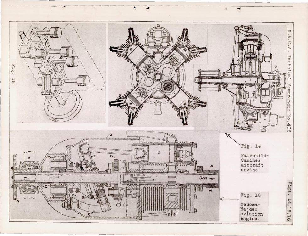
Figure 14 shows the American Fairchild Caminez 150 HP. air
plane engine of 1928 . In this constructional type (by no ~eans
new), the pi stons act directly on a lei:miscate-shaped cam which
makes only one revolution for every two working cycles of the
piston. T11e propeller speed is therefore automatically reduced
to half the hypothetical engine-shaft Elpeed . The lemniscate-
shaped can1 permits, furthermore, perfect balancing of the masses
and equal working strokes in the opposite cylinders.
The light- metal pistons are connected by steel links, so
that they cannot get away from the cam. The piston pin lies in
a bronze bushing.
The constructor of this crun- type engine did not have a
free hand in the choice of the cylinder stroke and bore, these
being established, for a d,;aired stroke volume , by the most fav-
orable stroke-bore ratio, whereby the bore is always greater
than the stroke.
The data for the Fairchild Caminez engine are:
stroke, 115 mm
Bore, 143 II
Compression ratio € = 5.2
N = 150 HP. at n = 2400 R.P.M. (propeller speed 1200 R. P . M. )
~~ ___ ~J
N. A. C. A. Technical Memorandum No. 462 9
Flying weight without starter but with propeller hub
164 kg, or about 1.1 kg/HP.
Steel cylinders with alur.linum heads screwed on hot.
Only one rocker for each exhaust and intake valve
on the propeller shaft, which revolves at half
the speed of the engine shaft.
Lubrication by pressure punp, a scavenge pump forcing
the oil through a filter back into the oil tank.
In spite of the very high perfornance of 20.5 HP./
liter for air- cooled engines, its weight of 1.1
kg/HP is not particularly low.
An obvious disadvantage of this engine is that it requires
ve ry accurate mount ing, since too gre at a clearance between
pistons and cam, by reason of the absence of a damping oil
layer, results not only in a great noise but also in a rapid
wearing of the rollers o The advantage of low propeller speed
is not great enough to warrant such an expensive and sensit ive
type of const ruction. The normal clearance between cam and
rollers is 0.4 mm, though the engine is said to be able to
function with 0.9 clearance •
. In this connection, we should mention still another English
engine (Fig. 15), in which the pistons work through claw and
rocker arms on the peculiar engine shaft, whose three portions
revolve in two inclined binding pi eces . The constructor is in

N. A. C. A. Technical I.1oi.1ora.ndui:1 No . 462 10
opposition to the fundamental rule that the engine shaft should
constitute the backbone of an engine and should accordingly, be
as rig i d as possible.
He sees an advantage in the fact that the engine shaft is
not under the cylinders, but to one side , where it can be easily
inspected. Thus the height of the engine is reduced, which, in
the invento r 1 s opinion , predestines this engine for aircraft,
while the smalle r connecting r od oscillations should obviate the
need of crossheads in large Diesel engines.
An interesting and compl i cated example of a crankless engine,
from both the kinematic and constructive points of view, was
built a few years ago in America, namely, the Nedoma-Najder
ai r plane engine (Fig. 16), in which the cylinders and the wab
ble plate both revolve.
The stationary hollow shaft W rests at both ends of the
engine on the bearings A. Around it revolve the five cylinders
Z, and the housing G, which carries the flange for the
propel l er hub . The housing revolves on the hollow shaft W, in
long bushings and in a ball bearing A, at the propell e re A
bushing provided with a toothed gear
front end of the revolving housing .
Zl ' is screwed t o the
Zl meshes with the front
planet ar y gear Z 2' which t r ansfers its mot ion to the geared
bushing Z3' which revolves at the same speed as the housing
G, but in the opposite direction. The bushing B, .is keyed to

N.A.O.A. Technical Memorandum No. 462 11
Z3' on which the wabble plate revolves on two ball bearings,
being carried along by the arm 0, which is attached to the
housing.
Due to the opposite motions of the bushing B, and the
wabble plate T, the latter passes during each revolution,
through its maximum and minimum distance from each of the five
cylinders, executing thereby a complete working cycle in each
cylinder for each revolution of the housing. The five aluminum
cylinders of 70 mm diameter and 86 mm stroke, are each con-
trolled by a single slide valve. The slide valves are made of
cast iron and the pistons are made of aluminum.
The slide valves are actuated by five shafts provided wi til
helical grooves, which in turn have five gears whi ch mesh in a
gear rim attached to the stationary hollow shaft. Two of these
gears also operate the two oil pumps.
Wi th t~is monstrous construotion the inventor thought to
produce a light aircraft eng ine which, at n = 1400 R.P.M. and
N = 40 HP., would weigh about 74 kg, corresponding to 1.83
kg/HP.
Translation by National Advisory Oommittee for Aeronaut ics.

N. A. C.A. T 3chni c~1 Memor~ ndu~ ~o.~62
Thrust colls,r
Fi gs . l,2
Oil
Fig.l
Fig.2
~ line s of flow of the oi 1.
----- -- lines of equal pre s sure.
c 3ntc r of pr essure .
Mi chell thrust bearing for sh~fts of ship engines.
Piston
~ I )'" 1" Thrust block J=--- ,/ .02/ . 04 oil
,Zj;;/i? fl ·;,- ;:.;,Ir/;-;;:··;;;;··j~'}f ....-- I
W.:tbble plate
l8yer
Mi che ll thrust bearing in cr;:mklcss engine.

r
Fig .5 Section th~ough engine in front of wabble plate
\' , " i _~ __________ ~
Fig . 4 Longitudinal seotion
Fig.3 Sec tion thl'ougb piato.n and valves.
z :» (")
:»
>-3 Cl> o ::>' :::l ~
o
'" I-'
Flo; Cl>
5 <i \ll :::J §' ~
z o ·
,j:>. (J) t\J
'%j ..... (JQ OJ . VI I.
01'> w
01
J

N . A. 0 . A. T8chni ca.1 r\~3moranjun No. ·162
~--4-----+--~----+----r~' -~4
.--If-----+----+-~
1000 1800 n
Mi chell Motor 8(84 ~ x 90)=~ I
"
2600
mkg
20 Q) ;j 0' f-i o
f!-'f 10
American motor car 6(88 r/lx127)= t1. 6 5, 1 -- - - - - - - --
Fig.6
Fig .S Oo mparison between Uichall engine and American motor car engine .

~ o
z > ~
o z > r
• o < iii a ~ ~
o a
" " ~ ~
'" '" ~ a ~
> '" ~ a z • c ~
n III
Figs . 7 & 8
ae!=l!;!~~, ~
- ....
Seotion t hrough Michell Diesel engine.
Figs.S & 10 l6-oylinder ~ six-stroKe ro tary 5 6 - ~ . - • . -
ang i ne of E. Laage. --~ -l,intake mixture ;2, compression I
3,expansion; 4-5, exhaust; 6. i n t a ke of scavenge air; 7-8, partia l exhaust of scavenge air
Fig.l3 "Ali" outboard eng-
Fi g .12 Sections between twol cylinder pairs above
the wabble pJate .
ine wi th cylinders removed, with a scavenging piston without working piston. Carburetor below at the right.
Fig.ll Seotion t hrough «;--- cylinder of ou t
board engine "Al i " .
'":l . ~ o 0-
1::1
""" o III I-'
s: l ~ o '1 g @' s z I? .t. m t\:)
..., """ OQ CD
-..J
CD
ill
I-' o I-' I-'
I-' t\)
I-' VI
L
' >:rj ......
(Jq
~ 01
· - ?II ~ 4
... . _. --:-. , \.
\ '.
\ \ \
\ \
\
\ \. '\
\. ., I I ... ,,-
.•.• ...... _'.
,<
~
, Fig. 14
Fairchi1dCaminez aircraft engine
Fig. 16
NedomaNajder avi at ion eng i ne.
z > o !I>
>-3 ~ o 0-::J ...... o P> f-'
~ (1)
s o >i C.! ::J §' S
Z o . ~ m N
':<j t-'.
oq CD
~
1~ ~ <n