Embed Size (px)
Citation preview
Surface & Coatings Technology xxx (2013) xxx–xxx
SCT-18297; No of Pages 10
Contents lists available at SciVerse ScienceDirect
Surface & Coatings Technology
j ourna l homepage: www.e lsev ie r .com/ locate /sur fcoat
Wear and corrosion performance of WC-10Co4Cr coatings deposited by differentHVOF and HVAF spraying processes
Qun Wang a,⁎, Shiying Zhang b, Yingliang Cheng a, Jing Xiang a, Xinqi Zhao a, Guibin Yang c
a College of Materials Science and Engineering, Hunan University, Changsha, Hunan 410082, PR Chinab Department of Biological and Environmental Science, Changsha University, Hunan 410003, PR Chinac Ganzhou Achteck Tool Technology Co., Ltd., Ganzhou, Jiangxi 341300, PR China
⁎ Corresponding author. Tel.: +86 13787113453; faxE-mail address: [email protected] (Q. Wang).
0257-8972/$ – see front matter © 2013 Elsevier B.V. Allhttp://dx.doi.org/10.1016/j.surfcoat.2012.12.041
Please cite this article as: Q. Wang, et al., S
a b s t r a c t
a r t i c l e i n f oArticle history:Received 7 September 2012Accepted in revised form 27 December 2012Available online xxxx
Keywords:HVAFWC-CoCr coatingAbrasive wearSliding wearElectrochemical corrosion
This study compares three types of WC-10Co4Cr coatings deposited with high-velocity oxygen fuel (HVOF) andhigh-velocity air fuel (HVAF) spraying processes. The experimental results indicated that the decarburisation ofthe WC in the WC-10Co4Cr coating was dramatically influenced by the spraying equipment, and the non-WCphase content in the as-sprayed coatings greatly influenced their performances. The HVAF-sprayedWC-10Co-4Cr coating revealed the lowest degree of decarburisation, achieving the best properties in terms ofhardness, fracture toughness, abrasive and sliding wear as well as electrochemical corrosion resistance whencompared to the two HVOF-sprayed WC-10Co-4Cr coatings.
© 2013 Elsevier B.V. All rights reserved.
1. Introduction
Tungsten carbide (WC)-based powders are widely used in high-velocity oxygen fuel (HVOF) spraying to produce dense coatings withhigh hardness and excellent wear resistance [1,2].
Although substantial improvement in coating properties can beobtained when spraying WC-cermets using the HVOF processinstead of a plasma spraying technique, various degrees of the WCdecarburisation still occur during the deposition process. A largenumber of researchers have reported that the decarburisation of WChas a detrimental effect on the abrasive wear resistance of coatingsdue to the increasing brittleness and the decrease in hard particlecontent [2–5]. Thus, there is a need for a spraying equipment thatoperates at a much lower temperature and generates a higher flamevelocity. A high-velocity air fuel (HVAF) system that uses gas or liquidfuel and compressed air (not oxygen) for combustion has been ex-plored to meet this need [4–8], and it has been found that depositingWC-based coatings by the HVAF spraying process can reduce the pro-duction cost due to the use of air instead of pure oxygen, while greatlydecreasing the degree of WC [4,5,9] or Cr3C2 [10] decarburisation as aresult of much lower flame temperature. Jacobs et al. [4,5] found thatHVAF-sprayed WC-based coatings exhibited a higher degree of hard-ness and improved sliding wear performance without decarburisationas compared to the HVOFmethod and attributed the higher wear resis-tance to the greater retention ofWC particles in the former coating type.
: +86 731 88821611.
rights reserved.
urf. Coat. Technol. (2013), ht
They also suggested that much more research was needed to compareperformance of coatings deposited by the HVAF and HVOF sprayingprocesses, especially for HVOF guns that use oxygen and kerosene forcombustion. Furthermore, although the corrosion performance ofHVOF-sprayed WC/Co(Cr) was studied in detail in the literature[11–15], the corrosion performance of the HVAF-sprayed WC/Co(Cr)coating has not yet been reported.
In this study, three WC-10Co4Cr coatings were deposited withsimilar powder using Kermetico's AK 07 HVAF spray system (AK) op-erating with propane and compressed air, the Praxair's JP8000 HVOFspray system (JP) operating with kerosene and pure oxygen, and theDeloro Stellite's Jet Kote® III HVOF spray system (JK) operating withpropylene and pure oxygen. The microstructures, mechanical proper-ties, abrasive and sliding wear as well as the electrochemical corro-sion resistances of the as-sprayed coatings were investigated.
2. Experiment
2.1. Materials
The WC-10Co4Cr powder (Ganzhou Achteck Tool Technology Co.,Ltd, China) was sprayed on a low-carbon steel substrate using HVAFand HVOF equipment. The same lot of the material was spray-driedand agglomerated, sintered into sprayable particles in the same pro-cess, and then sieved to obtain two powder types with different sizedistributions. Fine powder with the particle size of 5–30 μm wasused for the HVAF process and the coarse powder with the particlesize of 15–45 μm was used for the two HVOF processes. These twoWC-10Co4Cr powders had similar chemical compositions (mass
tp://dx.doi.org/10.1016/j.surfcoat.2012.12.041
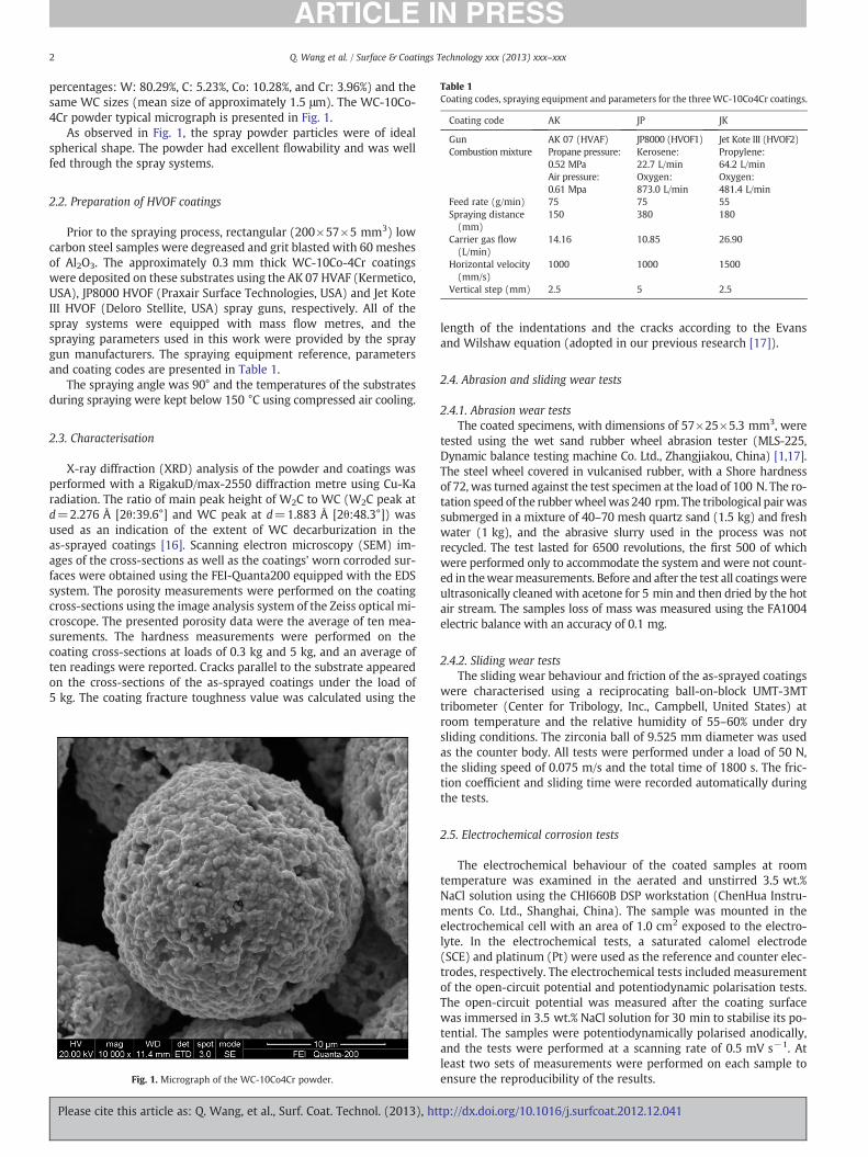
Table 1Coating codes, spraying equipment and parameters for the threeWC-10Co4Cr coatings.
Coating code AK JP JK
Gun AK 07 (HVAF) JP8000 (HVOF1) Jet Kote III (HVOF2)Combustion mixture Propane pressure:
0.52 MPaAir pressure:0.61 Mpa
Kerosene:22.7 L/minOxygen:873.0 L/min
Propylene:64.2 L/minOxygen:481.4 L/min
Feed rate (g/min) 75 75 55Spraying distance(mm)
150 380 180
Carrier gas flow(L/min)
14.16 10.85 26.90
Horizontal velocity(mm/s)
1000 1000 1500
Vertical step (mm) 2.5 5 2.5
2 Q. Wang et al. / Surface & Coatings Technology xxx (2013) xxx–xxx
percentages: W: 80.29%, C: 5.23%, Co: 10.28%, and Cr: 3.96%) and thesame WC sizes (mean size of approximately 1.5 μm). The WC-10Co-4Cr powder typical micrograph is presented in Fig. 1.
As observed in Fig. 1, the spray powder particles were of idealspherical shape. The powder had excellent flowability and was wellfed through the spray systems.
2.2. Preparation of HVOF coatings
Prior to the spraying process, rectangular (200×57×5 mm3) lowcarbon steel samples were degreased and grit blasted with 60 meshesof Al2O3. The approximately 0.3 mm thick WC-10Co-4Cr coatingswere deposited on these substrates using the AK 07 HVAF (Kermetico,USA), JP8000 HVOF (Praxair Surface Technologies, USA) and Jet KoteIII HVOF (Deloro Stellite, USA) spray guns, respectively. All of thespray systems were equipped with mass flow metres, and thespraying parameters used in this work were provided by the spraygun manufacturers. The spraying equipment reference, parametersand coating codes are presented in Table 1.
The spraying angle was 90° and the temperatures of the substratesduring spraying were kept below 150 °C using compressed air cooling.
2.3. Characterisation
X-ray diffraction (XRD) analysis of the powder and coatings wasperformed with a RigakuD/max-2550 diffraction metre using Cu-Karadiation. The ratio of main peak height of W2C to WC (W2C peak atd=2.276 Å [2θ:39.6°] and WC peak at d=1.883 Å [2θ:48.3°]) wasused as an indication of the extent of WC decarburization in theas-sprayed coatings [16]. Scanning electron microscopy (SEM) im-ages of the cross-sections as well as the coatings' worn corroded sur-faces were obtained using the FEI-Quanta200 equipped with the EDSsystem. The porosity measurements were performed on the coatingcross-sections using the image analysis system of the Zeiss optical mi-croscope. The presented porosity data were the average of ten mea-surements. The hardness measurements were performed on thecoating cross-sections at loads of 0.3 kg and 5 kg, and an average often readings were reported. Cracks parallel to the substrate appearedon the cross-sections of the as-sprayed coatings under the load of5 kg. The coating fracture toughness value was calculated using the
Fig. 1. Micrograph of the WC-10Co4Cr powder.
Please cite this article as: Q. Wang, et al., Surf. Coat. Technol. (2013), ht
length of the indentations and the cracks according to the Evansand Wilshaw equation (adopted in our previous research [17]).
2.4. Abrasion and sliding wear tests
2.4.1. Abrasion wear testsThe coated specimens, with dimensions of 57×25×5.3 mm3, were
tested using the wet sand rubber wheel abrasion tester (MLS-225,Dynamic balance testing machine Co. Ltd., Zhangjiakou, China) [1,17].The steel wheel covered in vulcanised rubber, with a Shore hardnessof 72, was turned against the test specimen at the load of 100 N. The ro-tation speed of the rubberwheel was 240 rpm. The tribological pair wassubmerged in a mixture of 40–70 mesh quartz sand (1.5 kg) and freshwater (1 kg), and the abrasive slurry used in the process was notrecycled. The test lasted for 6500 revolutions, the first 500 of whichwere performed only to accommodate the system and were not count-ed in thewearmeasurements. Before and after the test all coatingswereultrasonically cleaned with acetone for 5 min and then dried by the hotair stream. The samples loss of mass was measured using the FA1004electric balance with an accuracy of 0.1 mg.
2.4.2. Sliding wear testsThe sliding wear behaviour and friction of the as-sprayed coatings
were characterised using a reciprocating ball-on-block UMT-3MTtribometer (Center for Tribology, Inc., Campbell, United States) atroom temperature and the relative humidity of 55–60% under drysliding conditions. The zirconia ball of 9.525 mm diameter was usedas the counter body. All tests were performed under a load of 50 N,the sliding speed of 0.075 m/s and the total time of 1800 s. The fric-tion coefficient and sliding time were recorded automatically duringthe tests.
2.5. Electrochemical corrosion tests
The electrochemical behaviour of the coated samples at roomtemperature was examined in the aerated and unstirred 3.5 wt.%NaCl solution using the CHI660B DSP workstation (ChenHua Instru-ments Co. Ltd., Shanghai, China). The sample was mounted in theelectrochemical cell with an area of 1.0 cm2 exposed to the electro-lyte. In the electrochemical tests, a saturated calomel electrode(SCE) and platinum (Pt) were used as the reference and counter elec-trodes, respectively. The electrochemical tests included measurementof the open-circuit potential and potentiodynamic polarisation tests.The open-circuit potential was measured after the coating surfacewas immersed in 3.5 wt.% NaCl solution for 30 min to stabilise its po-tential. The samples were potentiodynamically polarised anodically,and the tests were performed at a scanning rate of 0.5 mV s−1. Atleast two sets of measurements were performed on each sample toensure the reproducibility of the results.
tp://dx.doi.org/10.1016/j.surfcoat.2012.12.041
3Q. Wang et al. / Surface & Coatings Technology xxx (2013) xxx–xxx
3. Results
3.1. Phase compositions
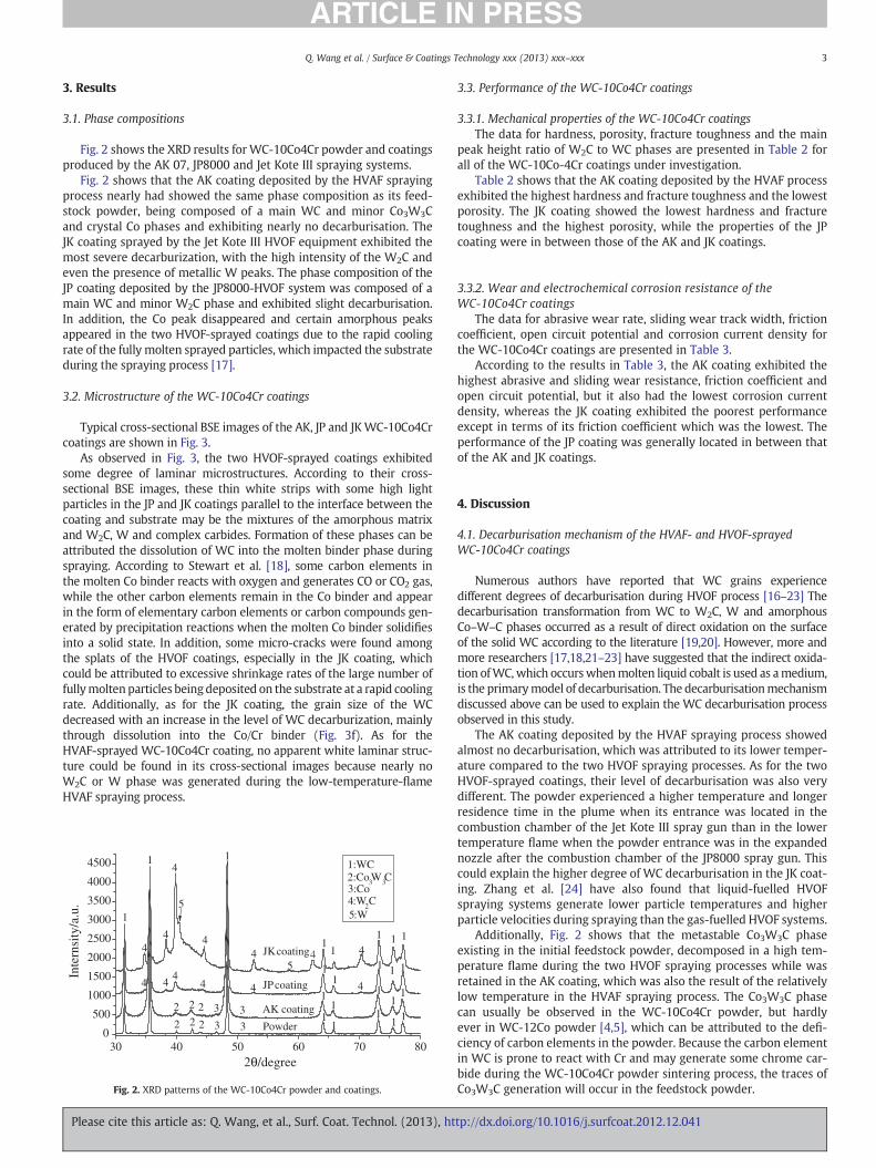
Fig. 2 shows the XRD results for WC-10Co4Cr powder and coatingsproduced by the AK 07, JP8000 and Jet Kote III spraying systems.
Fig. 2 shows that the AK coating deposited by the HVAF sprayingprocess nearly had showed the same phase composition as its feed-stock powder, being composed of a main WC and minor Co3W3Cand crystal Co phases and exhibiting nearly no decarburisation. TheJK coating sprayed by the Jet Kote III HVOF equipment exhibited themost severe decarburization, with the high intensity of the W2C andeven the presence of metallic W peaks. The phase composition of theJP coating deposited by the JP8000-HVOF system was composed of amain WC and minor W2C phase and exhibited slight decarburisation.In addition, the Co peak disappeared and certain amorphous peaksappeared in the two HVOF-sprayed coatings due to the rapid coolingrate of the fully molten sprayed particles, which impacted the substrateduring the spraying process [17].
3.2. Microstructure of the WC-10Co4Cr coatings
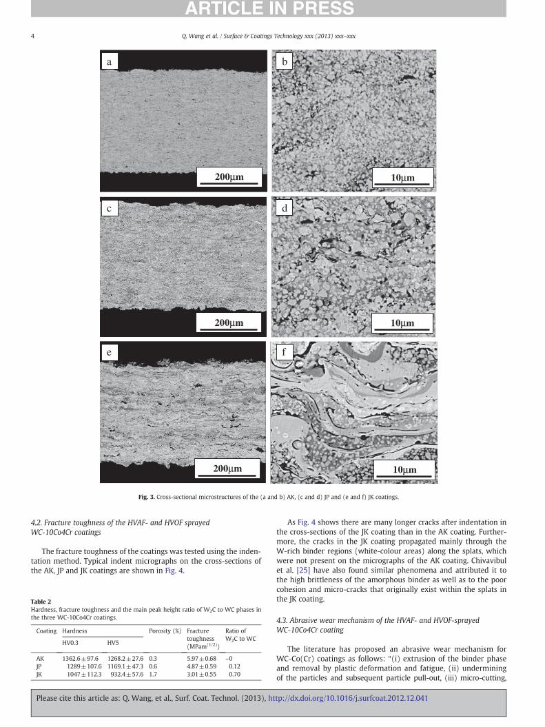
Typical cross-sectional BSE images of the AK, JP and JKWC-10Co4Crcoatings are shown in Fig. 3.
As observed in Fig. 3, the two HVOF-sprayed coatings exhibitedsome degree of laminar microstructures. According to their cross-sectional BSE images, these thin white strips with some high lightparticles in the JP and JK coatings parallel to the interface between thecoating and substrate may be the mixtures of the amorphous matrixand W2C, W and complex carbides. Formation of these phases can beattributed the dissolution of WC into the molten binder phase duringspraying. According to Stewart et al. [18], some carbon elements inthe molten Co binder reacts with oxygen and generates CO or CO2 gas,while the other carbon elements remain in the Co binder and appearin the form of elementary carbon elements or carbon compounds gen-erated by precipitation reactions when the molten Co binder solidifiesinto a solid state. In addition, some micro-cracks were found amongthe splats of the HVOF coatings, especially in the JK coating, whichcould be attributed to excessive shrinkage rates of the large number offullymolten particles beingdeposited on the substrate at a rapid coolingrate. Additionally, as for the JK coating, the grain size of the WCdecreased with an increase in the level of WC decarburization, mainlythrough dissolution into the Co/Cr binder (Fig. 3f). As for theHVAF-sprayed WC-10Co4Cr coating, no apparent white laminar struc-ture could be found in its cross-sectional images because nearly noW2C or W phase was generated during the low-temperature-flameHVAF spraying process.
30 40 50 60 70 800
500
1000
1500
2000
2500
3000
3500
4000
4500
4JK coating
JP coating
AK coating
Powder
11
3:Co
5:W
45
4:W2C5
44
4
44
444 4
3
4
3222
111
11
11 1:WC2:Co3W3C
1
2θ/degree
Inte
rnsi
ty/a
.u.
33222
4
1111
1
11
1
11 11
1
Fig. 2. XRD patterns of the WC-10Co4Cr powder and coatings.
Please cite this article as: Q. Wang, et al., Surf. Coat. Technol. (2013), ht
3.3. Performance of the WC-10Co4Cr coatings
3.3.1. Mechanical properties of the WC-10Co4Cr coatingsThe data for hardness, porosity, fracture toughness and the main
peak height ratio of W2C to WC phases are presented in Table 2 forall of the WC-10Co-4Cr coatings under investigation.
Table 2 shows that the AK coating deposited by the HVAF processexhibited the highest hardness and fracture toughness and the lowestporosity. The JK coating showed the lowest hardness and fracturetoughness and the highest porosity, while the properties of the JPcoating were in between those of the AK and JK coatings.
3.3.2. Wear and electrochemical corrosion resistance of theWC-10Co4Cr coatings
The data for abrasive wear rate, sliding wear track width, frictioncoefficient, open circuit potential and corrosion current density forthe WC-10Co4Cr coatings are presented in Table 3.
According to the results in Table 3, the AK coating exhibited thehighest abrasive and sliding wear resistance, friction coefficient andopen circuit potential, but it also had the lowest corrosion currentdensity, whereas the JK coating exhibited the poorest performanceexcept in terms of its friction coefficient which was the lowest. Theperformance of the JP coating was generally located in between thatof the AK and JK coatings.
4. Discussion
4.1. Decarburisation mechanism of the HVAF- and HVOF-sprayedWC-10Co4Cr coatings
Numerous authors have reported that WC grains experiencedifferent degrees of decarburisation during HVOF process [16–23] Thedecarburisation transformation from WC to W2C, W and amorphousCo–W–C phases occurred as a result of direct oxidation on the surfaceof the solid WC according to the literature [19,20]. However, more andmore researchers [17,18,21–23] have suggested that the indirect oxida-tion ofWC,which occurswhenmolten liquid cobalt is used as amedium,is the primarymodel of decarburisation. The decarburisationmechanismdiscussed above can be used to explain the WC decarburisation processobserved in this study.
The AK coating deposited by the HVAF spraying process showedalmost no decarburisation, which was attributed to its lower temper-ature compared to the two HVOF spraying processes. As for the twoHVOF-sprayed coatings, their level of decarburisation was also verydifferent. The powder experienced a higher temperature and longerresidence time in the plume when its entrance was located in thecombustion chamber of the Jet Kote III spray gun than in the lowertemperature flame when the powder entrance was in the expandednozzle after the combustion chamber of the JP8000 spray gun. Thiscould explain the higher degree of WC decarburisation in the JK coat-ing. Zhang et al. [24] have also found that liquid-fuelled HVOFspraying systems generate lower particle temperatures and higherparticle velocities during spraying than the gas-fuelled HVOF systems.
Additionally, Fig. 2 shows that the metastable Co3W3C phaseexisting in the initial feedstock powder, decomposed in a high tem-perature flame during the two HVOF spraying processes while wasretained in the AK coating, which was also the result of the relativelylow temperature in the HVAF spraying process. The Co3W3C phasecan usually be observed in the WC-10Co4Cr powder, but hardlyever in WC-12Co powder [4,5], which can be attributed to the defi-ciency of carbon elements in the powder. Because the carbon elementin WC is prone to react with Cr and may generate some chrome car-bide during the WC-10Co4Cr powder sintering process, the traces ofCo3W3C generation will occur in the feedstock powder.
tp://dx.doi.org/10.1016/j.surfcoat.2012.12.041
ba
c d
e f
10μm
10μm
10μm
200μm
200μm
200μm
Fig. 3. Cross-sectional microstructures of the (a and b) AK, (c and d) JP and (e and f) JK coatings.
4 Q. Wang et al. / Surface & Coatings Technology xxx (2013) xxx–xxx
4.2. Fracture toughness of the HVAF- and HVOF sprayedWC-10Co4Cr coatings
The fracture toughness of the coatings was tested using the inden-tation method. Typical indent micrographs on the cross-sections ofthe AK, JP and JK coatings are shown in Fig. 4.
Table 2Hardness, fracture toughness and the main peak height ratio of W2C to WC phases inthe three WC-10Co4Cr coatings.
Coating Hardness Porosity (%) Fracturetoughness(MPam(1/2))
Ratio ofW2C to WC
HV0.3 HV5
AK 1362.6±97.6 1268.2±27.6 0.3 5.97±0.68 ~0JP 1289±107.6 1169.1±47.3 0.6 4.87±0.59 0.12JK 1047±112.3 932.4±57.6 1.7 3.01±0.55 0.70
Please cite this article as: Q. Wang, et al., Surf. Coat. Technol. (2013), ht
As Fig. 4 shows there are many longer cracks after indentation inthe cross-sections of the JK coating than in the AK coating. Further-more, the cracks in the JK coating propagated mainly through theW-rich binder regions (white-colour areas) along the splats, whichwere not present on the micrographs of the AK coating. Chivavibulet al. [25] have also found similar phenomena and attributed it tothe high brittleness of the amorphous binder as well as to the poorcohesion and micro-cracks that originally exist within the splats inthe JK coating.
4.3. Abrasive wear mechanism of the HVAF- and HVOF-sprayedWC-10Co4Cr coating
The literature has proposed an abrasive wear mechanism forWC-Co(Cr) coatings as follows: “(i) extrusion of the binder phaseand removal by plastic deformation and fatigue, (ii) underminingof the particles and subsequent particle pull-out, (iii) micro-cutting,
tp://dx.doi.org/10.1016/j.surfcoat.2012.12.041
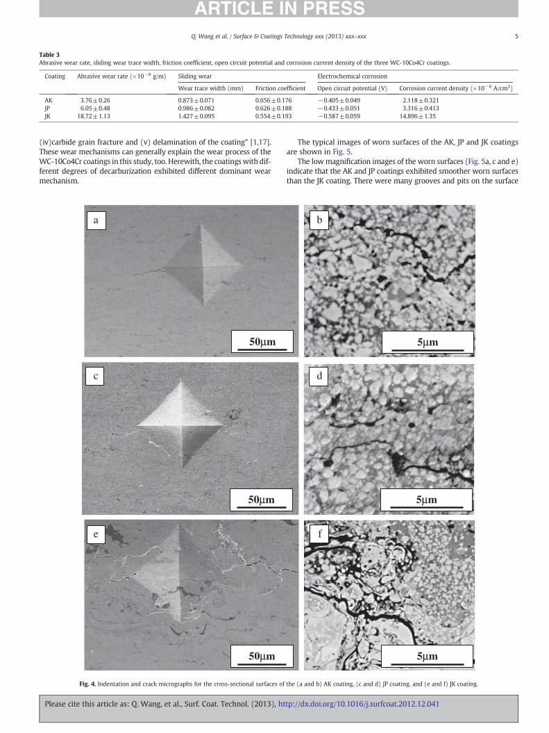
Table 3Abrasive wear rate, sliding wear trace width, friction coefficient, open circuit potential and corrosion current density of the three WC-10Co4Cr coatings.
Coating Abrasive wear rate (×10−6 g/m) Sliding wear Electrochemical corrosion
Wear trace width (mm) Friction coefficient Open circuit potential (V) Corrosion current density (×10−6 A/cm2)
AK 3.76±0.26 0.873±0.071 0.656±0.176 −0.405±0.049 2.118±0.321JP 6.05±0.48 0.986±0.082 0.626±0.188 −0.433±0.051 3.316±0.413JK 18.72±1.13 1.427±0.095 0.554±0.193 −0.587±0.059 14.896±1.35
5Q. Wang et al. / Surface & Coatings Technology xxx (2013) xxx–xxx
(iv)carbide grain fracture and (v) delamination of the coating” [1,17].These wear mechanisms can generally explain the wear process of theWC-10Co4Cr coatings in this study, too. Herewith, the coatingswith dif-ferent degrees of decarburization exhibited different dominant wearmechanism.
50μm
50μm
50μm
a
c
e
Fig. 4. Indentation and crack micrographs for the cross-sectional surfaces of
Please cite this article as: Q. Wang, et al., Surf. Coat. Technol. (2013), ht
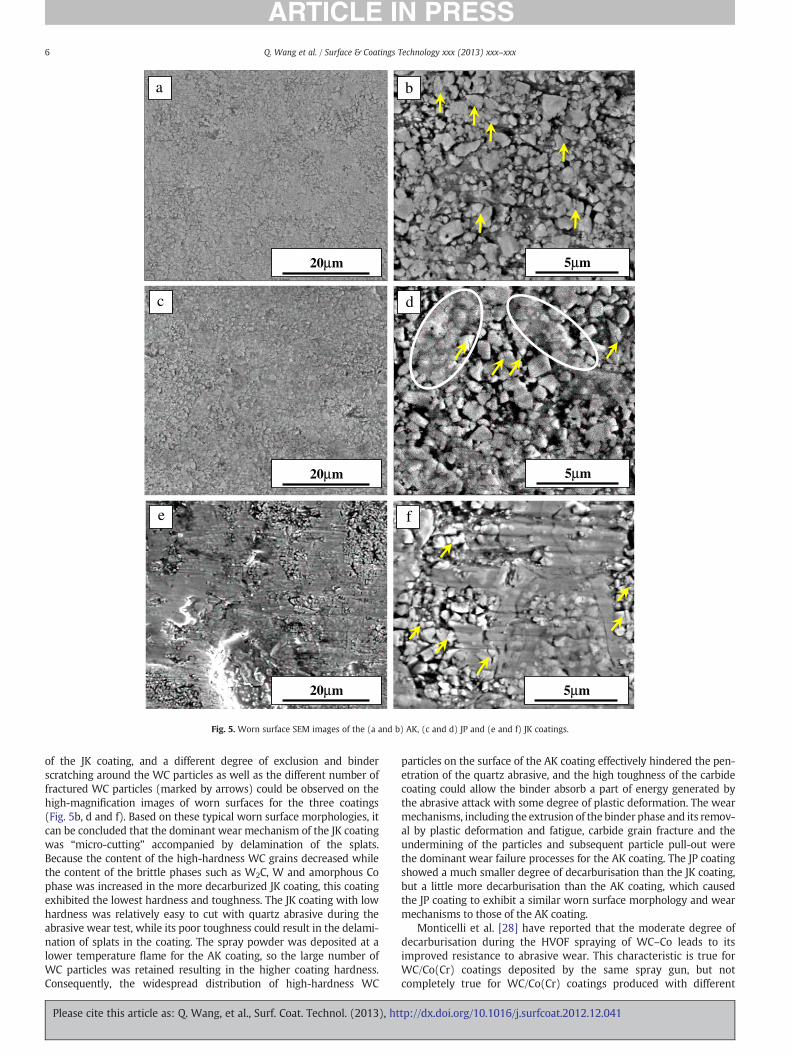
The typical images of worn surfaces of the AK, JP and JK coatingsare shown in Fig. 5.
The lowmagnification images of the worn surfaces (Fig. 5a, c and e)indicate that the AK and JP coatings exhibited smoother worn surfacesthan the JK coating. There were many grooves and pits on the surface
5μm
5μm
5μm
b
d
f
the (a and b) AK coating, (c and d) JP coating, and (e and f) JK coating.
tp://dx.doi.org/10.1016/j.surfcoat.2012.12.041
20μm
a
20μm
c
e
20μm
5μm
d
f
5μm
b
5μm
Fig. 5. Worn surface SEM images of the (a and b) AK, (c and d) JP and (e and f) JK coatings.
6 Q. Wang et al. / Surface & Coatings Technology xxx (2013) xxx–xxx
of the JK coating, and a different degree of exclusion and binderscratching around the WC particles as well as the different number offractured WC particles (marked by arrows) could be observed on thehigh-magnification images of worn surfaces for the three coatings(Fig. 5b, d and f). Based on these typical worn surface morphologies, itcan be concluded that the dominant wear mechanism of the JK coatingwas “micro-cutting” accompanied by delamination of the splats.Because the content of the high-hardness WC grains decreased whilethe content of the brittle phases such as W2C, W and amorphous Cophase was increased in the more decarburized JK coating, this coatingexhibited the lowest hardness and toughness. The JK coating with lowhardness was relatively easy to cut with quartz abrasive during theabrasive wear test, while its poor toughness could result in the delami-nation of splats in the coating. The spray powder was deposited at alower temperature flame for the AK coating, so the large number ofWC particles was retained resulting in the higher coating hardness.Consequently, the widespread distribution of high-hardness WC
Please cite this article as: Q. Wang, et al., Surf. Coat. Technol. (2013), ht
particles on the surface of the AK coating effectively hindered the pen-etration of the quartz abrasive, and the high toughness of the carbidecoating could allow the binder absorb a part of energy generated bythe abrasive attack with some degree of plastic deformation. The wearmechanisms, including the extrusion of the binder phase and its remov-al by plastic deformation and fatigue, carbide grain fracture and theundermining of the particles and subsequent particle pull-out werethe dominant wear failure processes for the AK coating. The JP coatingshowed a much smaller degree of decarburisation than the JK coating,but a little more decarburisation than the AK coating, which causedthe JP coating to exhibit a similar worn surface morphology and wearmechanisms to those of the AK coating.
Monticelli et al. [28] have reported that the moderate degree ofdecarburisation during the HVOF spraying of WC–Co leads to itsimproved resistance to abrasive wear. This characteristic is true forWC/Co(Cr) coatings deposited by the same spray gun, but notcompletely true for WC/Co(Cr) coatings produced with different
tp://dx.doi.org/10.1016/j.surfcoat.2012.12.041
7Q. Wang et al. / Surface & Coatings Technology xxx (2013) xxx–xxx
spray guns. For example, the AK coating deposited by the AK 07 HVAFspray gun without decarburisation exhibited higher wear resistancethan the JP coatings deposited by the JP8000 HVOF spray gun,which showed only slight decarburisation in this study.
4.4. Sliding wear mechanism of the HVAF- and HVOF-sprayedWC-10Co4Cr coatings
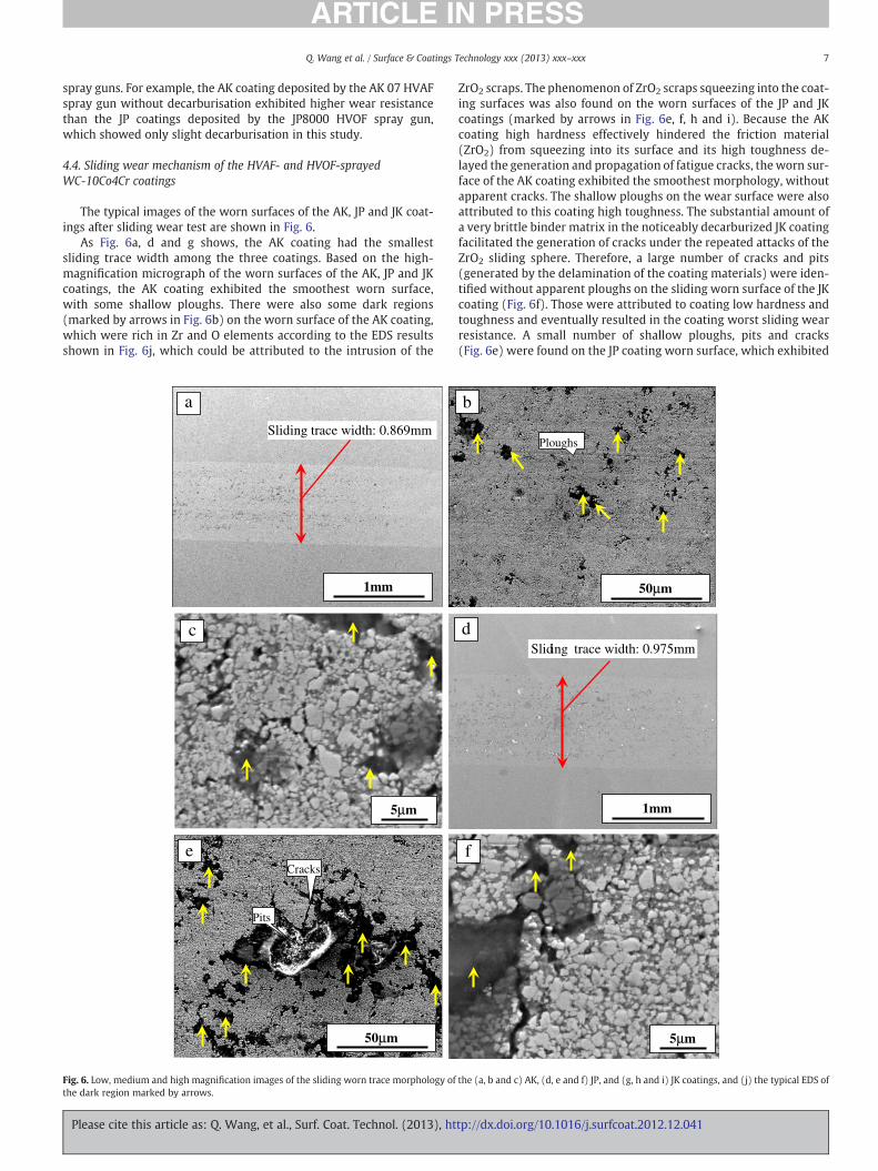
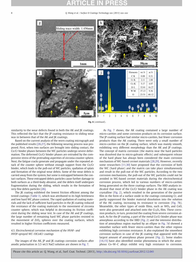
The typical images of the worn surfaces of the AK, JP and JK coat-ings after sliding wear test are shown in Fig. 6.
As Fig. 6a, d and g shows, the AK coating had the smallestsliding trace width among the three coatings. Based on the high-magnification micrograph of the worn surfaces of the AK, JP and JKcoatings, the AK coating exhibited the smoothest worn surface,with some shallow ploughs. There were also some dark regions(marked by arrows in Fig. 6b) on the worn surface of the AK coating,which were rich in Zr and O elements according to the EDS resultsshown in Fig. 6j, which could be attributed to the intrusion of the
c
a
5μm
1mm
Sliding trace width: 0.869mm
50μm
Cracks
Pits
e
Fig. 6. Low, medium and high magnification images of the sliding worn trace morphology ofthe dark region marked by arrows.
Please cite this article as: Q. Wang, et al., Surf. Coat. Technol. (2013), ht
ZrO2 scraps. The phenomenon of ZrO2 scraps squeezing into the coat-ing surfaces was also found on the worn surfaces of the JP and JKcoatings (marked by arrows in Fig. 6e, f, h and i). Because the AKcoating high hardness effectively hindered the friction material(ZrO2) from squeezing into its surface and its high toughness de-layed the generation and propagation of fatigue cracks, the worn sur-face of the AK coating exhibited the smoothest morphology, withoutapparent cracks. The shallow ploughs on the wear surface were alsoattributed to this coating high toughness. The substantial amount ofa very brittle binder matrix in the noticeably decarburized JK coatingfacilitated the generation of cracks under the repeated attacks of theZrO2 sliding sphere. Therefore, a large number of cracks and pits(generated by the delamination of the coating materials) were iden-tified without apparent ploughs on the sliding worn surface of the JKcoating (Fig. 6f). Those were attributed to coating low hardness andtoughness and eventually resulted in the coating worst sliding wearresistance. A small number of shallow ploughs, pits and cracks(Fig. 6e) were found on the JP coating worn surface, which exhibited
d
5μm
Sliding trace width: 0.975mm
f
1mm
b
50μm
Ploughs
the (a, b and c) AK, (d, e and f) JP, and (g, h and i) JK coatings, and (j) the typical EDS of
tp://dx.doi.org/10.1016/j.surfcoat.2012.12.041
h g
5μm
50μm1mm
Sliding trace width: 1.456mm
Cracks
Pits
i Elements wt.% at.%
C K 0.08 0.31
Cr K 2.11 1.88
Co K 5.17 4.07
Zr L 32.01 16.27
W M 37.13 9.36
O 23.51 68.12
j
Fig. 6 (continued).
8 Q. Wang et al. / Surface & Coatings Technology xxx (2013) xxx–xxx
similarity to the wear defects found in both the AK and JK coatings.This reflected the fact that the JP coating resistance to sliding wearwas in between that of the AK and JK coatings.
Based on the current analysis of the worn coating micrograph andthe published results [26,27], the following wearing process was pro-posed. First, when two surfaces are brought into sliding contact, theCo/Cr binder phases between the WC particles undergo severe defor-mation. The deformed Co/Cr binder phases are extruded by the com-pressive stress of the protruding asperities of zirconia counter sphere.Next, the fatigue cracks generate and propagate under the repeated at-tack of the counter sphere without enough support from the Co/Crbinder, which leads to the pull-out of WC particles, spallation of splatsand formation of the original wear debris. Some of the wear debris iscarried away from the system, but some is entrapped between the con-tact surfaces. These entrapped debris particles cause further damage toboth surfaces as a third-body abrasive, and the debris itself undergoesfragmentation during the sliding, which results in the formation ofvery fine debris particles [26].
The JK coating exhibited the lowest friction efficient among thetested coatings (Table 3), which was attributed to its high brittlenessand low hardWC phase content. The rapid spallation of coating mate-rials and the lack of sufficient hard particles in the JK coating reducedthe resistance of the coating materials to the movement of zirconiacounter sphere, which was helpful in decreasing its friction coeffi-cient during the sliding wear test. In case of the AK and JP coatings,the large number of remaining hard WC phase particles resisted tothe movement of ZrO2 spheres over the coating surfaces, whichresulted in higher friction coefficients measured.
4.5. Electrochemical corrosion mechanism of the HVAF- andHVOF-sprayed WC-10Co4Cr coatings
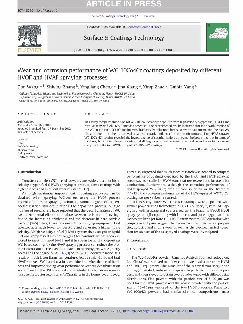
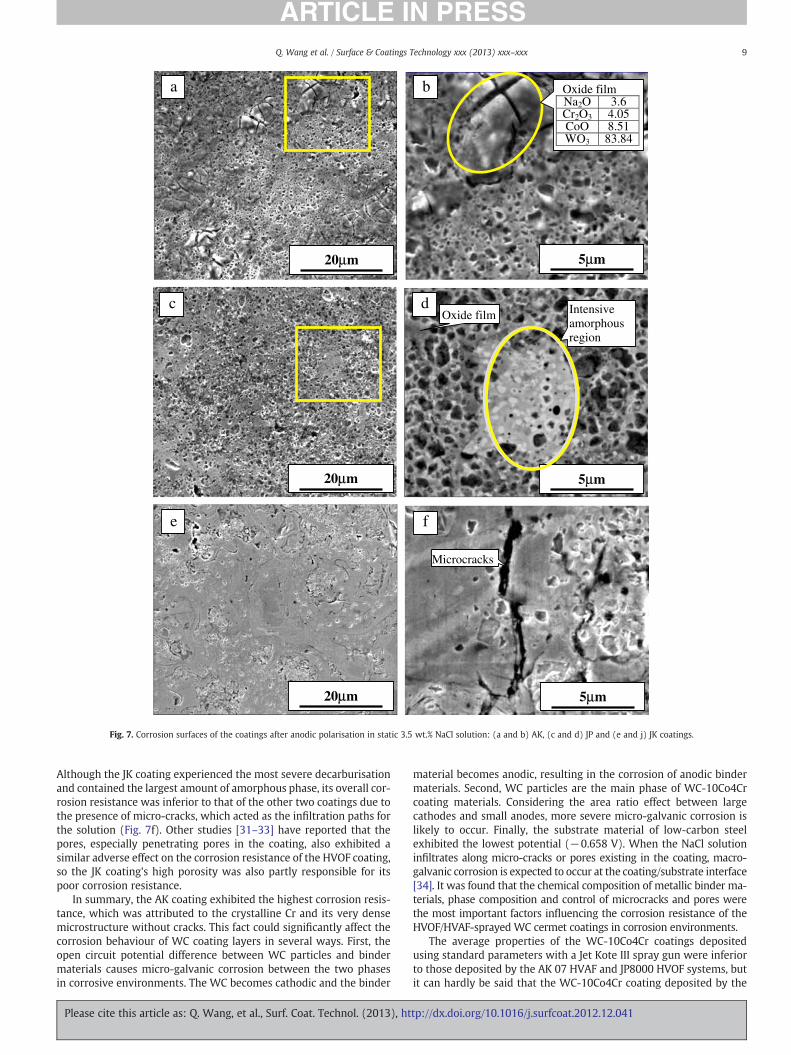
The images of the AK, JP and JK coatings corrosion surfaces afteranodic polarisation in 3.5 wt.% NaCl solution are shown in Fig. 7.
Please cite this article as: Q. Wang, et al., Surf. Coat. Technol. (2013), ht
As Fig. 7 shows, the AK coating contained a large number ofmicro-cavities and some corrosion products on its corrosion surface.The JP coating surface had similar micro-cavities, but fewer corrosionproducts than the AK coating. There were only a small number ofmicro-cavities on the JK coating surface, which was mainly smooth,exhibiting very different morphology than the AK and JP coatings.The concept of matrix corrosion (the matrix near the hard particleswas dissolved due to micro-galvanic effects) and subsequent releaseof the hard phase has always been considered the main corrosionmechanism of WC-based cermet materials [28,29]. However, recentlysome researchers [11,30] have proposed that the corrosion of boththe WC (hard phase) and the matrix can take place simultaneouslyand result in the pull-out of the WC particles. According to the twocorrosion mechanisms, the pull-out of the WC particles could not beavoided in WC-based cermet materials during the electrochemicalcorrosion process, which led to various numbers of micro-cavitiesbeing generated on the three coatings surfaces. The XRD analysis in-dicated that most of the Co/Cr binder phase in the AK coating wascrystalline (Fig. 2), which resulted in the generation of the passivefilm in the form of a surface oxide in the coatings containing Cr, andpartly suppressed the binder material dissolution into the solutionof the AK coating, increasing its resistance to corrosion (Fig. 7b).Meanwhile, the other types of oxide films, such as WO3 and CoO,were also generated and attached onto the Cr2O3 film. These corro-sion products, in turn, protected the coating from severe corrosion at-tack. As for the JP coating, a part of the metal Co/Cr binder phase wasamorphous according to the XRD (Fig. 2) and the intensive distribu-tion of amorphous region marked by an ellipse in Fig. 7d showed asmoother surface with fewer micro-cavities than the other regionsexhibiting high corrosion resistance. It also explained the smoothestcorrosion surfaces in case of the JK coating that appeared with thelargest amount of amorphous phase present (Fig. 2). Some studies[14,15] have also identified similar phenomena in which the amor-phous Co–W–C alloys exhibit very high resistance to corrosion.
tp://dx.doi.org/10.1016/j.surfcoat.2012.12.041
20μm
20μm
5μm20μm
5μm
5μm
a b
c d
f
Oxide filmNa2O 3.6 Cr2O3 4.05 CoO 8.51 WO3 83.84
Intensive amorphous region
Microcracks
Oxide film
e
Fig. 7. Corrosion surfaces of the coatings after anodic polarisation in static 3.5 wt.% NaCl solution: (a and b) AK, (c and d) JP and (e and j) JK coatings.
9Q. Wang et al. / Surface & Coatings Technology xxx (2013) xxx–xxx
Although the JK coating experienced the most severe decarburisationand contained the largest amount of amorphous phase, its overall cor-rosion resistance was inferior to that of the other two coatings due tothe presence of micro-cracks, which acted as the infiltration paths forthe solution (Fig. 7f). Other studies [31–33] have reported that thepores, especially penetrating pores in the coating, also exhibited asimilar adverse effect on the corrosion resistance of the HVOF coating,so the JK coating's high porosity was also partly responsible for itspoor corrosion resistance.
In summary, the AK coating exhibited the highest corrosion resis-tance, which was attributed to the crystalline Cr and its very densemicrostructure without cracks. This fact could significantly affect thecorrosion behaviour of WC coating layers in several ways. First, theopen circuit potential difference between WC particles and bindermaterials causes micro-galvanic corrosion between the two phasesin corrosive environments. The WC becomes cathodic and the binder
Please cite this article as: Q. Wang, et al., Surf. Coat. Technol. (2013), ht
material becomes anodic, resulting in the corrosion of anodic bindermaterials. Second, WC particles are the main phase of WC-10Co4Crcoating materials. Considering the area ratio effect between largecathodes and small anodes, more severe micro-galvanic corrosion islikely to occur. Finally, the substrate material of low-carbon steelexhibited the lowest potential (−0.658 V). When the NaCl solutioninfiltrates along micro-cracks or pores existing in the coating, macro-galvanic corrosion is expected to occur at the coating/substrate interface[34]. It was found that the chemical composition of metallic binder ma-terials, phase composition and control of microcracks and pores werethe most important factors influencing the corrosion resistance of theHVOF/HVAF-sprayed WC cermet coatings in corrosion environments.
The average properties of the WC-10Co4Cr coatings depositedusing standard parameters with a Jet Kote III spray gun were inferiorto those deposited by the AK 07 HVAF and JP8000 HVOF systems, butit can hardly be said that the WC-10Co4Cr coating deposited by the
tp://dx.doi.org/10.1016/j.surfcoat.2012.12.041
10 Q. Wang et al. / Surface & Coatings Technology xxx (2013) xxx–xxx
Jet Kote spray gun always exhibited poor performance. A significantamount of optimisation work should be performed on both the feed-stock powder and the spraying parameters for this spraying system.
5. Conclusion
Three WC-10Co4Cr coatings were deposited by HVOF and HVAFprocesses and their microstructure and properties were investigatedin this study. The following conclusions were drawn as a result.
(1) The WC-10Co4Cr coating deposited by the HVAF spraying pro-cess exhibited nearly the same phase composition as its initialfeedstock powder, which included mainly the WC and someCo3W3C and crystal Co phases with nearly no decarburisation.The JK coating sprayed with Jet Kote III-HVOF equipmentexhibited the most severe decarburisation with high-intensityW2C and even metallic W phase. The phase composition ofthe JP coating deposited by the JP8000-HVOF system was com-posed of main WC and minor W2C peaks and exhibited a lightdegree of decarburisation.
(2) The wear resistance and mechanism of the HVOF/HVAF-sprayedcoatings were influenced not only by their hardness but also bytheir fracture toughness. The high hardness of carbide coatingcould effectively hinder the cuts caused by the abrasives, andtheir high toughness could make the binder absorb some of theenergy caused by abrasive attacks with some degree of plasticdeformation.
(3) The WC-10Co4Cr coatings, which had different degrees ofdecarburisation, exhibited different dominant wear mechanisms.
(4) The electrochemical corrosion resistances and mechanisms ofHVAF- and HVOF-sprayedWC-10Co4Cr coatings were influencedby their phase compositions and microstructures.
Acknowledgements
This research was supported by the Project of Training Targets ofYoungKey Teachers of CommonCollege&University inHunanProvince,the Fundamental Research Funds for the Central University and theProjection of Young Teacher's Growth.
Please cite this article as: Q. Wang, et al., Surf. Coat. Technol. (2013), ht
References
[1] Q. Wang, Z.H. Chen, Z.X. Ding, Tribol. Int. 42 (7) (2009) 1046.[2] S.F. Wayne, S. Sarnpath, J. Therm. Spray Technol. 1 (4) (1992) 307.[3] Z. Yao, J. Stiglich, T.S. Sudarshan, Met. Powder Rep. 53 (2) (1998) 32.[4] L. Jacobs, M.M. Hyland, M.D. Bonte, J. Therm. Spray Technol. 8 (1) (1999) 125.[5] L. Jacobs, M.M. Hyland, M. De Bonte, J. Therm. Spray Technol. 7 (2) (1998) 213.[6] A. Verstak, V. Baranovski, in: B.R. Marple, M.M. Hyland, Y.-C. Lan, R.S. Lima, J. Voger
(Eds.), AC-HVAF Sprayed Tungsten Carbide: Properties and Applications, ThermalSpray 2006: Building on 100 Years of Success, ASM International, Seattle, WA, May15–18, 2006, (paper 11827).
[7] A. Verstak, V. Baranovski, Deposition of carbides by activated combustion HVAFspraying, thermal spray solutions: advances in technology and application, May10–14, 2004 (Osaka, Japan), DVS — German Welding Society, 2004, p. 551.
[8] R.Q. Guo, C. Zhang, Q. Chen, Y. Yang, N. Li, L. Liu, Corros. Sci. 53 (7) (2011) 2351.[9] S.L. Liu, X.P. Zheng, G.Q. Geng, Wear 269 (5–6) (2010) 362.
[10] S. Matthews, M. Hyland, B. James, J. Therm. Spray Technol. 13 (4) (2004) 526.[11] V.A.D. Souza, A. Neville, J. Therm. Spray Technol. 15 (1) (2006) 106.[12] JoanM. Perry, AnneNeville, TrevorHodgkiess, J. Therm. Spray Technol. 11 (2002) 536.[13] M. Magnani, P.H. Suegama, N. Espallargas, S. Dosta, C.S. Fugivara, J.M. Guilemany,
A.V. Benedetti, Surf. Coat. Technol. 202 (19) (2008) 4746.[14] H. Capel, P.H. Shipway, S.J. Harris, Wear 255 (2003) 917.[15] P.H. Shipway, L. Howell, Wear 258 (2005) 303.[16] Y. Ishikawa, J. Kawakita, S. Osawa, T. Itsukaichi, Y. Sakamoto, M. Takaya, S. Kuroda,
J. Therm. Spray Technol. 14 (3) (2005) 384.[17] Q. Wang, L.X. Li, G.B. Yang, X.Q. Zhao, Z.X. Ding, Surf. Coat. Technol. 206 (19–20)
(2012) 4000.[18] D.A. Stewart, P.H. Shipway, D.G. Mccartney, Acta Mater. 48 (7) (2000) 1593.[19] M.S.A. Khan, T.W. Clyne, in: C.C. Berndt (Ed.), Thermal Spray: Practical Solutions
for Engineering Problems, ASM International, Materials Park, Ohio, 1996, p. 113.[20] P. Aroto, L. Bartha, R. Porat, S. Berger, A. Rosen, Nanostruct. Mater. 10 (1998) 245.[21] B.H. Kear, G. Skandan, R.K. Sadangi, Scr. Mater. 44 (8–9) (2001) 1703.[22] J.R. Fincke, W.D. Swank, D.C. Haggard, Proceedings of the 7th National Thermal
Spray Conference, ASM Int, Boston, 1994, p. 325.[23] C. Verdon, A. Karimi, J.L. Martin, Mater. Sci. Eng., A 246 (1–2) (1998) 11.[24] D. Zhang, S.J. Harris, D.G. McCartney, Mater. Sci. Eng., A 344 (1–2) (2003) 45.[25] P. Chivavibul, M. Watanabe, S. Kuroda, K. Shinoda, Surf. Coat. Technol. 202 (3)
(2007) 509.[26] Q. Yang, T. Senda, A. Ohmori, Wear 254 (1–2) (2003) 23.[27] S.H. Zhang, T.Y. Cho, J.Ho. Yoon, M.X. Li, P.W. Shum, S.C. Kwon, Mater. Sci. Eng. B
162 (2) (2003) 127.[28] C. Monticelli, A. Frignani, F. Zucchi, Corros. Sci. 46 (5) (2004) 1225.[29] A. Trueman, D.P. Schweinsberg, G.A. Hope, Corros. Sci. 41 (7) (1999) 1377.[30] M. Takeda, N. Morihiro, R. Ebara, Y. Harada, Mater. Trans. 43 (11) (2002) 2860.[31] G. Bolelli, R. Giovanardi, L. Lusvarghi, T. Manfredini, Corros. Sci. 48 (11) (2006) 3375.[32] P.H. Suegama, C.S. Fugivara, A.V. Benedetti, J. Fernández, J. Delgado, J.M. Guilemany,
Corros. Sci. 47 (3) (2005) 605.[33] I.B. Singh, D.P. Mandal, M. Singh, S. Das, Corros. Sci. 51 (2) (2009) 234.[34] J.E. Cho, S.Y. Hwang, K.Y. Kim, Surf. Coat. Technol. 200 (8) (2006) 2653.
tp://dx.doi.org/10.1016/j.surfcoat.2012.12.041