Embed Size (px)
Citation preview
Arch. Metall. Mater., Vol. 61 (2016), No 2B, p. 1201–1206
DOI: 10.1515/amm-2016-0199
M. SOLECKA*#, M. KOPYŚCIAŃSKI*, J. KUSIŃSKI*, A. KOPIA*, A. RADZISZEWSKA*
EROSIVE WEAR OF INCONEL 625 ALLOY COATINGS DEPOSITED BY CMT METHOD
The article presents the investigation results concerning the determination of the characteristics of erosive wear caused by the impact of Al2O3 solid particles on the surface of Inconel 625 alloy after plastic working and the same material after weld cladding process using the CMT method. Erosion wear tests were performed at two temperatures: 20°C and 650°C. The erosion tests were conducted using the standard ASTM G76. A jet with a specified abrasive waight was directed to the surface of the tested material at an α impingement angle varied in the range of 30-90° at a velocity imparted to the abrasive by the medium, which was com-pressed air. The eroded surface was examined using a scanning electron microscope (SEM), while the depths of craters caused by the erosion tests were measured with an optical profilometer. The predominant mechanisms of the formation of mass losses during solid particle erosion were microcutting and microfissuring.
Keywords: Inconel 625, erosion wear, solid particles erosion, alloys
1. Introduction
The development in the power industry involves the design and construction of power units with an efficiency exceeding the existing throughout. The need for designing power units that use alternative fuels entails the design and development of materials that meet a number of requirements imposed on power engineering materials. Compared to currently used materials, new materials are required to have: increased creeping resistance, enhanced heat resistance, high resistance to aggressive media containing e.g. the compounds of oxygen, sulphur or chlorine, increased service life and wear resistance, especially erosive and erosive-corrosive wear. To satisfy all these requirements, the development of new materials for of power boilers is required [1-3]. A considerable part of industrial elements undergo erosive wear. A perfect example of such wear can be the elements of airtight walls, furnace tubes and fluidized-bed boilers. Solid particle erosion in the elements of tube and boiler installations occur when an oxide layer delaminate from the surfaces of boiler burner tubes, walls and boilers. Thus released solid particles have a size of up to 300 μm and a hardness of approx. 750 HV. Erosive wear causes an increase in the downtime of equipment and, as a consequence, a decrease in effectiveness [2,4,5]. A com-mon subjects of excessive erosion are the tubes of fluidized-bed boiler proper membrane walls in the region immediately above the combustion chamber hopper brickwork end, as well as the platen surfaces. The mechanism of intensive erosive wear of parts operating at elevated temperatures is often due to the surface erosive wear rate exceeding the rate of protective oxide layer
* AGH, UNIVERSITY OF SCIENCE AND TECHNOLOGY, AL. A. MICKIEWICZA 30, 30-059 KRAKOW, POLAND# Corresponding author: [email protected]
formation [4]. The intensity of the erosive wear of an industrial part can be substantially reduced by producing a wear-resistant coating. The use of coatings is a cheaper solution to the protec-tion of a part, compared to the manufacture of the complete part from wear-resistant materials. Moreover, applied coatings combine the advantageous properties of the core with the good corrosive-erosive and heat-resisting properties of the coating [5-8]. Currently, such coatings are applied by weld cladding of appropriate materials on the steel substrate [9]. Weld cladding is a method of applying a material layer onto a product’s surface by welding. Compared to other coating application methods, such as thermal spraying [8], clad coatings are distinguished by a strong metallurgical bond with the substrate material, and a weld clad formed does not contain pores or other defects. A basic problem associated with weld cladding of nickel-based alloys onto steels is an excessive fusion of the base material and passing of its constituents (chiefly iron) to the coating. An excessive amount of iron in the coating material weld clad leads to a reduction in corrosion and erosion resistance [8,10]. Traditional welding processes, such as the MIG/MAG welding technique, are charac-terized by relatively little capability to control the heat delivered to the substrate and, as a consequence of which, the iron content of the weld clad is too high [11]. The CMT (Cold Metal Transfer) technique [11,12] has turned out to be an alternative and, at the same time, innovative weld cladding method. However, a lot of conducted research studies point out to the need for developing a high-temperature method for erosive wear testing of construc-tional materials, protective coatings and refractories [9,13,14]. Because of the complexity of the erosion process, the theoretical
1202
description of the erosive wear mechanism requires considerable simplifications. The sole knowledge of the kinetics of erosion of immovable material specimens in a solid particle jet is not sufficient for predicting the erosion resistance of constructional materials. This means that in the process of describing the ero-sion resistance of different types of materials, experimental tests will play a key role [15,16]. The aim of the investigation was to make a detailed analysis of the process of erosive wear of alloy protective coatings applied on power boiler parts by the CMT technique. As the reference material, Inconel 625 specimens cut out from a after plastic working were used.
2. Materials and methods
Solid particle erosive wear tests were conducted on two types of the Inconel 625 alloy. One of the materials was wrought Inconel 625, and the other – a weld clad coating applied on boiler steel 16Mo3 by the Cold Metal Transfer (CMT) method. Chemical composition of the tested alloy is given in Table 1.
TABLE 1
The chemical composition of Inconel 625 alloy, [wt %]
Alloys Ni Cr Mo Nb Fe C Mn SiInconel 625 balance 23.20 9.40 3.50 0.30 0.12 0.40 0.40
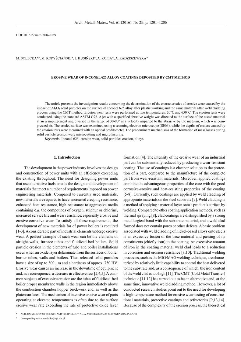
The erosive wear tests were performed using the author’s testing stand. The abrasion wear testing stand is shown in (Fig. 1). The proposed concept of the device for erosive wear process simulation refers to the method that reproduces the mechanism of impact erosion that is caused by the impact of hard particles, where the abrasive carrier is a stream of compressed air [17]. The basic objective was to enable the tests to be conducted under high-temperature conditions. To be able to perform the tests not only at ambient temperature, but also at an elevated temperature, the device was equipped with a pipe furnace, for which a special holder was designed to enable the control of the impingement angle of abrasive hitting the specimen. The erosive wear process simulation stand according to ASTM G 76 con-sisted of a compressed air source, an abrasive batching system, a mixing chamber and a nozzle [18]. Compressed air and solid particles are delivered to the mixing chamber, from where the mixture is discharged via a 1 mm-diameter 570 mm-long nozzle. After leaving the nozzle, accelerated abrasive particles carried by the air stream hit the surface of a test sample positioned at a distance of 5 mm from the nozzle, with a specified kinetic energy. During testing, the velocity of solid particles discharged from the nozzle should be approx. 90-110 m/s. The air flowrate should be maintained at a level of approx. 16 m3/h at a pressure of 0.3 MPa. The tests were conducted, respectively, at ambient temperature, i.e. 20°C, and at a temperature of 650°C, which simulates the boiler operation temperature. The test specimens, in the form of an 12×20×2 mm rectangular prism, were fixed on the table at an appropriate abrasive particle impingement angle.
Fig. 1. The diagram showing the position of to simulate erosive wear
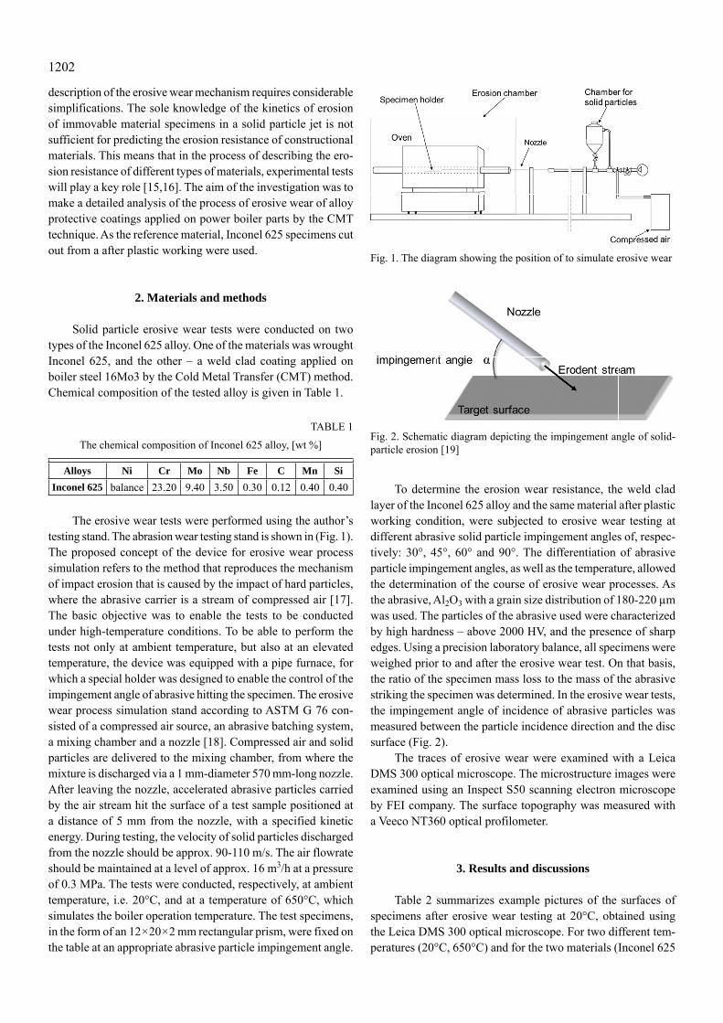
Fig. 2. Schematic diagram depicting the impingement angle of solid-particle erosion [19]
To determine the erosion wear resistance, the weld clad layer of the Inconel 625 alloy and the same material after plastic working condition, were subjected to erosive wear testing at different abrasive solid particle impingement angles of, respec-tively: 30°, 45°, 60° and 90°. The differentiation of abrasive particle impingement angles, as well as the temperature, allowed the determination of the course of erosive wear processes. As the abrasive, Al2O3 with a grain size distribution of 180-220 μm was used. The particles of the abrasive used were characterized by high hardness – above 2000 HV, and the presence of sharp edges. Using a precision laboratory balance, all specimens were weighed prior to and after the erosive wear test. On that basis, the ratio of the specimen mass loss to the mass of the abrasive striking the specimen was determined. In the erosive wear tests, the impingement angle of incidence of abrasive particles was measured between the particle incidence direction and the disc surface (Fig. 2).
The traces of erosive wear were examined with a Leica DMS 300 optical microscope. The microstructure images were examined using an Inspect S50 scanning electron microscope by FEI company. The surface topography was measured with a Veeco NT360 optical profilometer.
3. Results and discussions
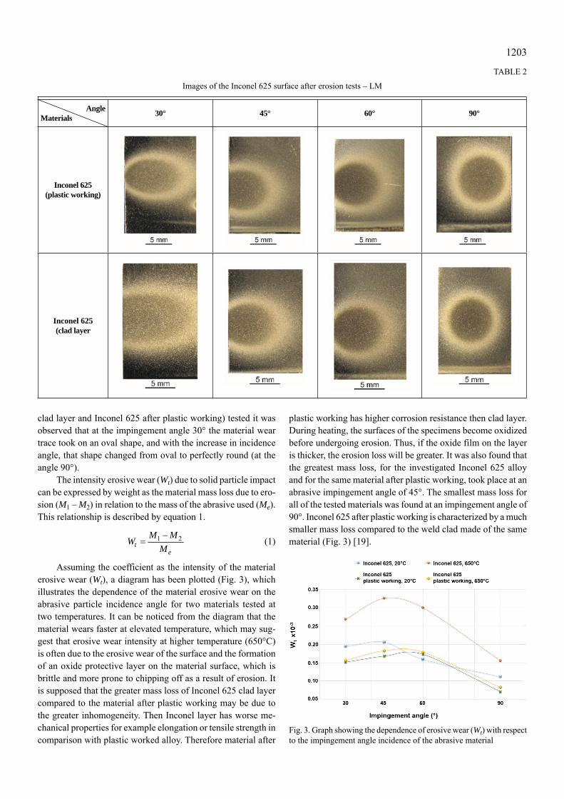
Table 2 summarizes example pictures of the surfaces of specimens after erosive wear testing at 20°C, obtained using the Leica DMS 300 optical microscope. For two different tem-peratures (20°C, 650°C) and for the two materials (Inconel 625
1203
clad layer and Inconel 625 after plastic working) tested it was observed that at the impingement angle 30° the material wear trace took on an oval shape, and with the increase in incidence angle, that shape changed from oval to perfectly round (at the angle 90°).
The intensity erosive wear (Wt) due to solid particle impact can be expressed by weight as the material mass loss due to ero-sion (M1 – M2) in relation to the mass of the abrasive used (Me). This relationship is described by equation 1.
1 2t
e
M MWM
(1)
Assuming the coefficient as the intensity of the material erosive wear (Wt), a diagram has been plotted (Fig. 3), which illustrates the dependence of the material erosive wear on the abrasive particle incidence angle for two materials tested at two temperatures. It can be noticed from the diagram that the material wears faster at elevated temperature, which may sug-gest that erosive wear intensity at higher temperature (650°C) is often due to the erosive wear of the surface and the formation of an oxide protective layer on the material surface, which is brittle and more prone to chipping off as a result of erosion. It is supposed that the greater mass loss of Inconel 625 clad layer compared to the material after plastic working may be due to the greater inhomogeneity. Then Inconel layer has worse me-chanical properties for example elongation or tensile strength in comparison with plastic worked alloy. Therefore material after
plastic working has higher corrosion resistance then clad layer. During heating, the surfaces of the specimens become oxidized before undergoing erosion. Thus, if the oxide film on the layer is thicker, the erosion loss will be greater. It was also found that the greatest mass loss, for the investigated Inconel 625 alloy and for the same material after plastic working, took place at an abrasive impingement angle of 45°. The smallest mass loss for all of the tested materials was found at an impingement angle of 90°. Inconel 625 after plastic working is characterized by a much smaller mass loss compared to the weld clad made of the same material (Fig. 3) [19].
Fig. 3. Graph showing the dependence of erosive wear (Wt) with respect to the impingement angle incidence of the abrasive material
TABLE 2
Images of the Inconel 625 surface after erosion tests – LM
AngleMaterials 30° 45° 60° 90°
Inconel 625(plastic working)
Inconel 625(clad layer
1204
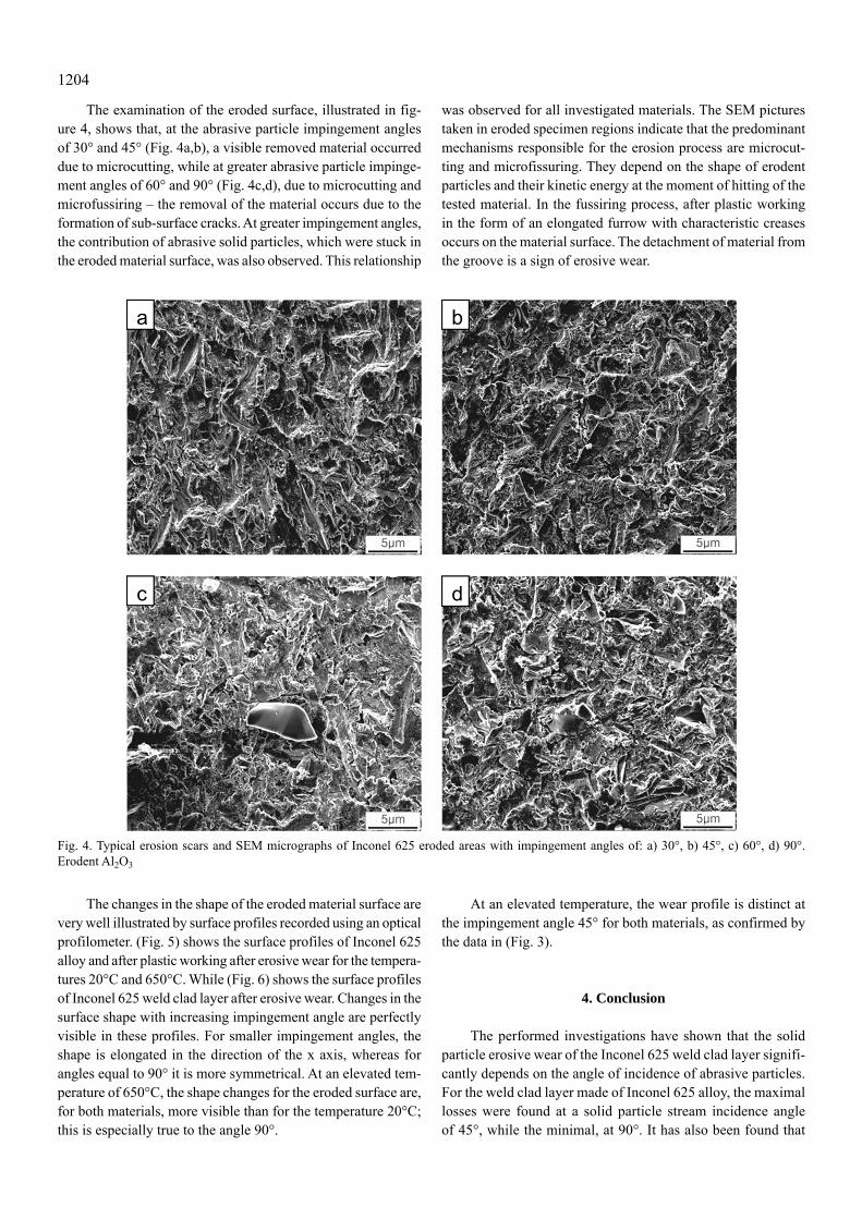
The examination of the eroded surface, illustrated in fig-ure 4, shows that, at the abrasive particle impingement angles of 30° and 45° (Fig. 4a,b), a visible removed material occurred due to microcutting, while at greater abrasive particle impinge-ment angles of 60° and 90° (Fig. 4c,d), due to microcutting and microfussiring – the removal of the material occurs due to the formation of sub-surface cracks. At greater impingement angles, the contribution of abrasive solid particles, which were stuck in the eroded material surface, was also observed. This relationship
was observed for all investigated materials. The SEM pictures taken in eroded specimen regions indicate that the predominant mechanisms responsible for the erosion process are microcut-ting and microfissuring. They depend on the shape of erodent particles and their kinetic energy at the moment of hitting of the tested material. In the fussiring process, after plastic working in the form of an elongated furrow with characteristic creases occurs on the material surface. The detachment of material from the groove is a sign of erosive wear.
Fig. 4. Typical erosion scars and SEM micrographs of Inconel 625 eroded areas with impingement angles of: a) 30°, b) 45°, c) 60°, d) 90°. Erodent Al2O3
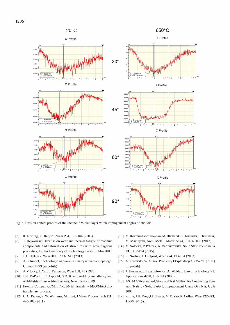
The changes in the shape of the eroded material surface are very well illustrated by surface profiles recorded using an optical profilometer. (Fig. 5) shows the surface profiles of Inconel 625 alloy and after plastic working after erosive wear for the tempera-tures 20°C and 650°C. While (Fig. 6) shows the surface profiles of Inconel 625 weld clad layer after erosive wear. Changes in the surface shape with increasing impingement angle are perfectly visible in these profiles. For smaller impingement angles, the shape is elongated in the direction of the x axis, whereas for angles equal to 90° it is more symmetrical. At an elevated tem-perature of 650°C, the shape changes for the eroded surface are, for both materials, more visible than for the temperature 20°C; this is especially true to the angle 90°.
At an elevated temperature, the wear profile is distinct at the impingement angle 45° for both materials, as confirmed by the data in (Fig. 3).
4. Conclusion
The performed investigations have shown that the solid particle erosive wear of the Inconel 625 weld clad layer signifi-cantly depends on the angle of incidence of abrasive particles. For the weld clad layer made of Inconel 625 alloy, the maximal losses were found at a solid particle stream incidence angle of 45°, while the minimal, at 90°. It has also been found that

1205
the removal of both the after plastic working material and the Inconel 625 weld clad layer takes place by microcutting and microfissuring.
Erosion at an elevated temperature of 650°C results in greater mass losses for the weld clad than for the material in an as wrought condition. The temperature increase is not the only cause of increasing susceptibility to erosion. Inconel 625 after plastic working condition exhibits greater erosive wear resistance compared to Inconel 625weld clad layer.
In the description of the erosive wear resistance of different types of constructional materials, a crucial role is played by the experimental methods of determining this property and rendering the operation conditions.
Acknowledgements
The authors would like to acknowledge the AGH-UST Faculty of Metals Engineering and Industrial Computer Science (Grant No. 15.1 1.1 10.345) for the financial support this work.
REFERENCES
[1] T. Hejwowski, Vacuum 83, 166-170 (2009).[2] J.G.A. Bitter, Wear 6, 5-21 (1963).[3] J.G.A. Bitter, Wear 6, 169-190 (1963).[4] A. Hernas, J. Dobrzański, Trwałość i niszczenie elementów kotłów
i turbin parowych, Gliwice 2003 (in polish).
Fig. 5. Erosion craters profiles in Inconel 625 after plastic working
1206
Fig. 6. Erosion craters profiles of the Inconel 625 clad layer witch impingement angles of 30°-90°
[5] R. Norling, I. Olefjord, Wear 254, 173-184 (2003).[6] T. Hejwowski, Treatise on wear and thermal fatigue of machine
components and fabrication of structures with advantageous properties, Lublin University of Technology Press, Lublin 2003.
[7] J. H. Tylczak, Wear 302, 1633-1641 (2013).[8] A. Klimpel, Technologie napawania i natryskiwania cieplnego,
Gliwice 1999 (in polish).[9] A.V. Levy, J. Yan, J. Patterson, Wear 108, 43 (1986).[10] J.N. DuPont, J.C. Lippold, S.D. Kiser, Welding metallurgy and
weldability of nickel-base Alloys, New Jersay 2009.[11] Fronius Company, CMT: Cold Metal Transfer – MIG/MAG dip-
transfer arc process.[12] C. G. Pickin, S. W. Williams, M. Lunt, J Mater Process Tech 211,
496-502 (2011).
[13] M. Rozmus-Górnikowska, M. Blicharski, J. Kusiński, L. Kusiński, M. Marszycki, Arch. Metall. Mater. 58 (4), 1093-1096 (2013).
[14] M. Solecka, P. Petrzak, A. Radziszewska, Solid State Phenomena 231, 119-124 (2015).
[15] R. Norling, I. Olefjord, Wear 254, 173-184 (2003).[16] A. Zbrowski, W. Mizak, Problemy Eksploatacji 3, 235-250 (2011)
(in polish).[17] J. Kusiński, J. Przybyłowicz, A. Woldan, Laser Technology VI:
Applications 4238, 101-114 (2000).[18] ASTM G76 Standard, Standard Test Method for Conducting Ero-
sion Tests by Solid Particle Impingement Using Gas Jets, USA 2000.
[19] R. Liu, J.H. Yao, Q.L. Zhang, M.X. Yao, R. Collier, Wear 322-323, 41-50 (2015).