Embed Size (px)
Citation preview
www.Fisher.com
Fisher™ Z500 Severe Service Ball ValvesThis bulletin covers Fisher NPS 1/2 36 Z500 SevereService Ball Valves. The Z500 severe service ball valveline is a simplistic two-piece floating ball design withintegral metal seat meant to provide tight shutoff inhigh temperature, high pressure, and erosiveapplications across all industries. The mate lapped balland seat constructions help ensure sealing and theHigh-Velocity Oxyfuel coatings (HVOF) provideexcellent corrosion resistance and help eliminate theproblems associated with severe service conditions.
Z500 valves are available with a variety of endconnections from ASME CL150 through CL4500.
All Z500 valves are designed and manufactured to beused in severe service applications. They are highlyengineered to help enhance safety in potentiallydangerous operating parameters and reduce valvemaintenance costs.
Features� Machined Stops -- Integral 90 degree lockplate
design prevents over-rotation and maintains criticalalignment on lever-operated valves.
� Side Mounted Bracket -- Helps prevent shaft andpacking box side load and bolt shear by attaching tothe side of the valve body. Allows easy access topacking gland nuts for needed adjustments.
� Live-Loaded Packing - Packing design utilizeslive-loaded spring washers for easy adjustment.Compact stuffing box and liveloaded Bellevillesprings ensure packing is continuously energizedand protects against shaft side loading andtemperature fluctuations.
� Shaft Adapter - Lever-operated valves have acontactproof shaft adapter designed to preventthe shaft from being knocked into the ball, causingmisalignment and possible leakage.
Fisher Z500 ValveX1243
� BlowOut Proof Shaft - Rugged, onepiece,machined, surface-hardened and polished shaft isdesigned to be blowout proof. There are no pins torely on, which helps increase safety and reliability.
� Integral Metal Seat - Preferred sealing seat ismachined into the end adapter, coated, and matelapped with the ball. Design eliminates a potentialleak path and helps the valve withstand highpressures, temperatures and severe serviceconditions.
� Metal Body Gasket - Specially engineered,selfenergizing gasket helps ensure that there is noleakage during thermal transients.
� High-Velocity Oxyfuel Coatings (HVOF) - Forms avery hard and dense coating on the base metal ofthe ball forming a strong mechanical bond.Typically these coatings are chrome or tungstencarbide. These coatings provide exceptional wear,corrosion, and erosion resistance.
(continued on page 2)
Z500 Ball ValvesD103992X012
Product Bulletin51.3:Z500
January 2020

Z500 Ball ValvesD103992X012
Product Bulletin51.3:Z500January 2020
2
Specifications
Valve Sizes
Z500: NPS � 1/2, � 3/4, � 1, � 1-1/2, � 2, � 3,� 4, � 6, � 8, � 10, � 12, � 14, � 16, � 18, � 20,� 24, � 26, � 28, � 30 and, � 36
Maximum Working Pressures(1)
Consistent with applicable pressure-temperatureratings in table 1 per ASME B16.34, but do not exceedthe material temperature capabilities shown below
Shutoff Classification(1)
Z500: Valves are tested to API 598 in the preferredflow direction.
Class V type B per FCI 70-2 in reverse flow inbi-directional design (Must be specified). For othershutoff requirements, please contact your Emersonsales office
Construction Materials
See table 2
Temperature Capabilities(1)
Welded and Threaded Ends: Carbon Steel: 427�C(800�F); F22: 593�C (1100�F); F91: 649�C (1200�F); F316: 538�C (1000�F); F316H: 760�C (1400�F)
Flanged End Connections: Carbon Steel: 316�C(600�F); F22: 427�C (800�F); F91: 538�C (1000�F); F316: 538�C (1000�F)
Lower Limits: Carbon steel: -29�C (-20�F), Stainless steel: -40�C (-40�F)
Packing Constructions
Carbon Steel Valve Bodies: Wire reinforced graphitepacking, AISI 4130 nitrided packing glandStainless Steel: N06600 wire-reinforced graphitepacking, S31600 nitrided packing gland
Dimensions
See figures 4 and 7 and tables 10 through 19 orcontact your Emerson sales office
Standard Flow Direction
Preferred Flow Direction: Preferred flow for optimalsealing is forward into the integral seat
Flow Coefficients
Contact your Emerson sales office
Maximum Ball Rotation
90 degrees
Actuator Mounting
The preferred mounting orientation is vertical. Otherorientations are acceptable
Approximate Weight
Contact your Emerson sales office
Options
� Reduced port, � Expanded outlet, � Scraperseats, � HVOF coating options, � Bi-directionalsealing, � High cycle constructions, � Lockouts,� Spray and fused coatings
1. The pressure/temperature limits in this bulletin, and any applicable code or standard limitation, should not be exceeded.
Features (continued)� Bi-Directional Sealing - Optional bi-directional
sealing is available for all configurations but must bespecified when ordering. Selecting this optiondesignates reverse flow sealing to ANSI/FCI 70-2Class V Type B shutoff classification.
� Sour Service Capability - Materials are available forapplications involving sour liquids and gases. Theseconstructions comply with NACE MR0103.
� Back Pressure Protection - Welded and threadedend connection valves with 0.65, 1.15, 1.5, and 2inch bores come standard with a seat holderdesigned to protect the Belleville spring from beingdeformed in case of process back pressure.

Z500 Ball ValvesD103992X012
Product Bulletin51.3:Z500
January 2020
3
Table 1. Valve Body Materials, End Connections, and RatingsRatings Bore (inches) Size, NPS End Connection Valve Body Materials(1)
CL150 through 1500
0.65
1/2
Buttweld, Socketweld, FNPT,
RF, RTJ
Carbon Steel, F22, F91,
F316, and F316H
3/4
1
1-1/2
1.15
1
1-1/2
2
2-1/2
1.5
1-1/2
2
2-1/2
3 Buttweld, RF, RTJ
2
2 Buttweld, Socketweld, FNPT,
RF, RTJ2-1/2
3
Buttweld, RF, RTJ
4
3
3
4
6
44
6
66
8
88
RF, RTJ
10
10 10
12 12
14 14
16 16
18 18
20 20
24 24
26 26
28 28
30 30
36 36
‐continued‐

Z500 Ball ValvesD103992X012
Product Bulletin51.3:Z500January 2020
4
Table 1. Valve Body Materials, End Connections, and Ratings (continued)Ratings Bore (inches) Size, NPS End Connection Valve Body Materials(1)
CL2500
0.65
1/2
Buttweld, Socketweld, FNPT,
RF, RTJ
Carbon Steel, F22, F91,
F316, and F316H
3/4
1
1-1/2
1.15
1
1-1/2
2
2-1/2
1.5
1-1/2
2
2-1/2
3 Buttweld, RF, RTJ
2
2 Buttweld, Socketweld, FNPT,
RF, RTJ2-1/2
3
Buttweld, RF, RTJ
4
3
3
4
6
44
6
66
8
88
RF, RTJ10
CL3200
0.65
1/2
Buttweld, SocketweldCarbon Steel, F22, F91,
F316, and F316H
3/4
1
1.15
1
1-1/2
2
1.5
1-1/2
2
2-1/2
CL4500
0.65
1/2
Buttweld, SocketweldCarbon Steel, F22, F91,
F316, and F316H
3/4
1
1.15
1
1-1/2
2
1.5
1-1/2
2
2-1/2
1. Valve bodies are machined from forgings or forged bar.

Z500 Ball ValvesD103992X012
Product Bulletin51.3:Z500
January 2020
5
Figure 1. Z500 Cross Section Construction Features
SEATHOLDER
BELLEVILLEWASHERS
BI-DIRECTIONAL DESIGN
UNI-DIRECTIONAL DESIGN
BALLBODY GASKET
GE88740
FLOWDIRECTION
UPSTREAM SEAT
VALVEBODY
PREFFEREDFLOWDIRECTION
GLANDPLATE
SHAFT
INTEGRAL SEAT
END ADAPTOR
BI-DIRECTIONALSPRING
THRUST WASHER
VALVEBODY
UPSTREAM SEAT BALL BODY GASKET
END ADAPTORINTEGRAL SEAT
BELLEVILLEWASHERSSHAFT
GLANDPLATE
UNI-DIRECTIONALSPRING
THRUST WASHER

Z500 Ball ValvesD103992X012
Product Bulletin51.3:Z500January 2020
6
Figure 2. Z500 Construction Features
BODYSTUD/NUT
SHAFT
SEAT HOLDER
VALVE BODY
SIDE-MOUNTEDBRACKET
X1207
UPSTREAMSEAT
BELLEVILLE SPRING
PACKING GLAND
METAL BODYGASKET
INTEGRALMETAL SEAT
END ADAPTER
LOCKPLATE
SHAFTADAPTER
BALL
SUPPORT BUSHING(HIGH CYCLEBRACKET ONLY)
PACKING STUDAND BELLEVILLEWASHERS
Note:��Seat holder is standard on welded and threaded end connections in 0.65, 1.15, 1.5, and 2 inch bores only. Bidirectional option must be specified for all other constructions.1
1
PACKING SET

Z500 Ball ValvesD103992X012
Product Bulletin51.3:Z500
January 2020
7
Table 2. Standard Construction Materials for NPS 1/2 through 36 Valves
PARTVALVE BODY AND END ADAPTER MATERIAL
Carbon Steel F22 F91 F316, F316H
Ball(1) S41000 S41000 S41000 S31600
Upstream seat(1) S41000 S41000 S41000 S31600
Seat Holder(2) S41000 S41000 S41000 S31600
Body gasket S17400 N07718 N07718 S66286
Spring N07718 or S17400(3) N07718 N07718 S66286
Packing Flexible graphite with wire-reinforced braided graphite and stainless steel washers
Shaft S17400 Nitrided N07718 Nitrided N07718 Nitrided S66286 Nitrided
Shaft adapter AISI 4130 Nitrided, 4140 Nitrided
Coatings HVOF Chrome Carbide (standard), HVOF Tungsten Carbide, Spray and Fused Nickel-Boron
1. Part is coated (HVOF chrome carbide standard)2. Seat holder is standard on welded and threaded end connections in 0.65, 1.15, 1.5, and 2 inch bores only. Bidirectional option must be specified for all other constructions.3. N07718 spring for 2 inch bore and below. S17400 spring for 3 inch bore and below.
Table 3. Spray and Fused Coating Standard Construction Materials(1)
PARTVALVE BODY AND END ADAPTER MATERIAL
Carbon Steel F22 F91 F316, F316H
Ball and Upstream Seat(2) F22 S31600
1. Seat holder is standard on welded and threaded end connections in 0.65, 1.15, 1.5, and 2 inch bores only. Bidirectional option must be specified for all other constructions.2. Part is coated.
Figure 3. Typical Z500 Packing Arrangement
PACKING WASHER
VALVE SHAFT
GE88834
PACKING LIVELOADED SPRINGS
PACKINGRING BRAIDED
PACKINGRING MOLDED
VALVE BODY
THRUST WASHER
PACKING GLAND
PACKING NUT
PACKING STUD

Z500 Ball ValvesD103992X012
Product Bulletin51.3:Z500January 2020
8
Pressure DropsPressure drop limits of any given valve are based onvalve body and material limits. Z500 valves meet fullB16.34 pressure drop capabilities up to specified
material maximum temperature limit. Information onlimits for other material constructions can be obtainedby contacting your Emerson sales office.
Table 4. Maximum Allowable Shutoff Pressure Drops (Body Ratings)
TEMPERATURERANGE
PRESSURE CLASS
Carbon SteelCL150
Carbon SteelCL300
Carbon SteelCL600
Carbon SteelCL900
Carbon SteelCL1500
Carbon SteelCL2500
Carbon SteelCL4500
�C Bar
-29 to 38 19.7 51.0 102.0 153.1 255.5 425.4 766.0
93 17.9 46.9 93.8 140.3 234.1 389.9 702.2
149 15.9 45.2 90.3 135.5 225.5 375.8 676.7
204 13.8 43.8 87.2 131.0 218.6 364.0 655.3
260 11.7 41.7 83.1 124.8 207.9 346.5 623.3
316 9.7 39.3 78.3 117.6 195.8 326.1 587.1
343(1) 8.6 37.9 75.8 113.8 189.3 315.4 568.1
371(1) 7.6 36.5 71.0 109.6 183.7 305.1 548.8
399(1) 6.6 34.8 70.0 104.8 174.8 291.6 524.7
427(1) 5.5 28.3 56.9 85.2 141.7 236.5 425.4
�F Psi
-20 to 100 285 740 1480 2220 3705 6170 11110
200 260 680 1360 2035 3395 5655 10185
300 230 655 1310 1965 3270 5450 9815
400 200 635 1265 1900 3170 5280 9505
500 170 605 1205 1810 3015 5025 9040
600 140 570 1135 1705 2840 4730 8515
650(1) 125 550 1100 1650 2745 4575 8240
700(1) 110 530 1030 1590 2665 4425 7960
750(1) 95 505 1015 1520 2535 4230 7610
800(1) 80 410 825 1235 2055 3430 6170
1. Due to material limitations, consult your Emerson sales office for flanged end connection use over 316�C (600�F).

Z500 Ball ValvesD103992X012
Product Bulletin51.3:Z500
January 2020
9
Table 5. Maximum Allowable Shutoff Pressure Drops (Body Ratings)
TEMPERATURERANGE
PRESSURE CLASS
F22Class 3CL150
F22Class 3CL300
F22Class 3CL600
F22Class 3CL900
F22Class 3CL1500
F22Class 3CL2500
F22Class 3CL4500
�C Bar
-29 to 38 20.0 51.7 103.4 155.1 258.6 430.9 775.7
93 17.9 51.7 103.4 155.1 258.6 430.9 775.7
149 15.9 50.3 100.3 150.7 251.0 418.5 753.3
204 13.8 48.6 97.2 145.8 243.4 405.4 729.8
260 11.7 45.9 91.7 137.6 229.3 382.0 687.1
316 9.7 41.7 83.4 125.1 208.6 347.5 625.4
343 8.6 40.7 81.0 121.7 202.7 338.2 608.5
371 7.6 39.3 78.3 117.6 195.8 326.1 587.1
399 6.6 36.5 73.4 110.0 183.4 305.4 549.5
427 5.5 35.2 70.0 105.1 175.1 291.6 524.7
454(1) 4.5 33.4 67.2 100.7 167.9 279.9 503.7
482(1) 3.4 31.0 62.1 93.1 154.8 258.2 464.7
510(1) 2.4 26.5 52.1 80.0 133.1 222.0 399.6
538(1) 1.4 18.3 36.9 55.2 92.0 153.8 276.5
566(1) 1.4 12.1 24.1 36.2 60.3 100.3 181.0
593(1) 1.4 7.6 15.2 22.8 37.9 63.1 113.4
�F Psi
-20 to 100 290 750 1500 2250 3750 6250 11250
200 260 750 1500 2250 3750 6250 11250
300 230 730 1455 2185 3640 6070 10925
400 200 705 1410 2115 3530 5880 10585
500 170 665 1330 1995 3325 5540 9965
600 140 605 1210 1815 3025 5040 9070
650 125 590 1175 1765 2940 4905 8825
700 110 570 1135 1705 2840 4730 8515
750 95 530 1065 1595 2660 4430 7970
800 80 510 1015 1525 2540 4230 7610
850(1) 65 485 975 1460 2435 4060 7305
900(1) 50 450 900 1350 2245 3745 6740
950(1) 35 385 755 1160 1930 3220 5795
1000(1) 20 265 535 800 1335 2230 4010
1050(1) 20 175 350 525 875 1455 2625
1100(1) 20 110 220 330 550 915 1645
1. Due to material limitations, consult your Emerson sales office for flanged end connection use over 427�C (800�F).

Z500 Ball ValvesD103992X012
Product Bulletin51.3:Z500January 2020
10
Table 6. Maximum Allowable Shutoff Pressure Drops (Body Ratings)
TEMPERATURERANGE
PRESSURE CLASS
F316, F316H(2)
CL150F316, F316H(2)
CL300F316, F316H(2)
CL600F316, F316H(2)
CL900F316, F316H(2)
CL1500F316, F316H(2)
CL2500F316, F316H(2)
CL4500
�C Bar
-29 to 38 19.0 49.6 99.3 148.9 248.2 413.7 744.6
93 16.2 42.7 85.5 128.2 213.4 355.8 640.5
149 14.8 38.6 77.2 115.8 192.7 321.3 578.5
204 13.4 35.5 70.7 106.2 177.2 295.1 531.2
260 11.7 33.1 65.8 98.9 164.8 274.4 494.0
316 9.7 31.0 62.1 93.4 155.5 259.2 466.8
343 8.6 30.3 61.0 91.4 152.4 253.7 456.8
371 7.6 30.0 60.0 90.0 149.6 249.6 456.1
399 6.6 29.3 59.0 88.3 147.2 245.5 442.0
427 5.5 29.0 58.3 87.2 145.5 242.7 436.8
454 4.5 29.0 57.6 86.5 144.1 239.9 432.0
482 3.4 28.6 57.2 85.8 143.1 238.6 429.5
510 2.4 26.5 53.4 80.0 133.1 222.0 399.6
538 1.4 25.2 50.0 75.2 125.5 208.9 375.8
566(1) 1.4 11.0 49.6 74.5 124.1 206.8 372.3
593(1) 1.4 21.0 42.1 63.1 105.1 175.5 315.4
621(1) 1.4 16.2 32.8 49.0 81.7 135.8 244.8
649(1) 1.4 12.8 25.5 38.3 63.8 106.5 191.3
677(1) 1.4 10 20.3 30.3 50.7 84.8 145.5
704(1) 1.4 7.9 16.2 24.1 40.3 66.9 120.6
732(1) 1.4 6.6 13.1 20 33.1 55.2 99.3
760(1) 1.4 5.2 10.3 15.5 26.2 43.4 77.9
�F Psi
-20 to 100 275 720 1440 2160 3600 6000 10800
200 235 620 1240 1860 3095 5160 9290
300 215 560 1120 1680 2795 4660 8390
400 195 515 1025 1540 2570 4280 7705
500 170 480 955 1435 2390 3980 7165
600 140 450 900 1355 2255 3760 6770
650 125 440 885 1325 2210 3680 6625
700 110 435 870 1305 2170 3620 6615
750 95 425 855 1280 2135 3560 6410
800 80 420 845 1265 2110 3520 6335
850 65 420 835 1255 2090 3480 6265
900 50 415 830 1245 2075 3460 6230
950 35 385 775 1160 1930 3220 5795
1000 20 365 725 1090 1820 3030 5450
1050(1) 20 160 720 1080 1800 3000 5400
1100(1) 20 305 610 915 1525 2545 4575
1150(1) 20 235 475 710 1185 1970 3550
1200(1) 20 185 370 555 925 1545 2775
1250(1) 20 145 295 440 735 1230 2110
1300(1) 20 115 235 350 585 970 1750
1350(1) 20 95 190 290 480 800 1440
1400(1) 20 75 150 225 380 630 1130
1. Due to material limitations, consult your Emerson sales office for flanged end connection use over 538�C (1000�F).2. Use F316H above 538�C (1000�F).

Z500 Ball ValvesD103992X012
Product Bulletin51.3:Z500
January 2020
11
Table 7. Maximum Allowable Shutoff Pressure Drops (Body Ratings)
TEMPERATURERANGE
PRESSURE CLASS
F91CL150
F91CL300
F91CL600
F91CL900
F91CL1500
F91CL2500
F91CL4500
�C Bar
-29 to 38 20.0 51.7 103.4 155.1 258.6 430.9 775.7
93 17.9 51.7 103.4 155.1 258.6 430.9 775.7
149 15.9 50.3 100.3 150.7 251.0 418.5 753.3
204 13.8 48.6 97.2 145.8 243.4 405.4 729.8
260 11.7 45.9 91.7 137.6 229.3 382.0 687.1
316 9.7 41.7 83.4 125.1 208.6 347.5 625.4
343 8.6 40.7 81.0 121.7 133.8 338.2 608.5
371 7.6 39.3 78.3 117.6 126.9 326.1 587.1
399 6.6 36.5 73.4 110.0 114.5 305.4 549.5
427 5.5 35.2 70.0 105.1 106.2 291.6 524.7
454 4.5 33.4 67.2 100.7 98.9 279.9 503.7
482 3.4 31.0 62.1 93.1 154.8 258.2 464.7
510 2.4 26.5 53.4 80.0 133.1 222.0 399.6
538 1.4 25.2 50.0 75.2 125.5 208.9 375.8
566(1) 1.4 24.8 49.6 74.5 124.1 206.8 448.2
593(1) 1.4 20.7 41.7 62.6 104.1 173.4 312.0
621(1) 1.4 15.5 30.7 46.2 76.9 127.9 230.6
649(1) 1.4 10.0 20.0 29.6 49.6 82.7 148.9
�F Psi
-20 to 100 290 750 1500 2250 3750 6250 11250
200 260 750 1500 2250 3750 6250 11250
300 230 730 1455 2185 3640 6070 10925
400 200 705 1410 2115 3530 5880 10585
500 170 665 1330 1995 3325 5540 9965
600 140 605 1210 1815 3025 5040 9070
650 125 590 1175 1765 1940 4905 8825
700 110 570 1135 1705 1840 4730 8515
750 95 530 1065 1595 1660 4430 7970
800 80 510 1015 1525 1540 4230 7610
850 65 485 975 1460 1435 4060 7305
900 50 450 900 1350 2245 3745 6740
950 35 385 775 1160 1930 3220 5795
1000 20 365 725 1090 1820 3030 5450
1050(1) 20 360 720 1080 1800 3000 6500
1100(1) 20 300 605 908 1510 2515 4525
1150(1) 20 225 445 670 1115 1855 3345
1200(1) 20 145 290 430 720 1200 2160
1. Due to material limitations, consult your Emerson sales office for flanged end connection use over 538�C (1000�F).

Z500 Ball ValvesD103992X012
Product Bulletin51.3:Z500January 2020
12
Table 8. Maximum Allowable Shutoff Pressure Drops - Limited Class (Valve Body Ratings)
Temper-ature
Range
CL 1500 CL 2500 CL 3200 CL 4500
CarbonSteel
F22 CL3 F91F316,
F316HCarbon
Steel F22 CL3 F91
F316,F316H
CarbonSteel
F22 CL3 F91F316,
F316HCarbon
SteelF22 CL3 F91
F316,F316H
°C Bar
-29 to 38 259 259 259 259 431 431 431 431 552 552 552 552 776 776 776 776
93 259 259 259 231 431 431 431 385 552 552 552 492 776 776 776 693
149 255 255 259 207 425 425 431 345 544 544 552 441 766 765 776 621
204 253 251 259 191 421 418 431 319 539 535 552 408 758 753 776 573
260 253 250 259 179 421 416 431 299 539 533 552 382 758 749 776 537
316 253 249 259 170 421 414 431 283 539 530 552 362 758 746 776 510
343 246 247 259 166 411 411 431 277 526 526 552 355 740 740 776 498
371 238 244 253 162 397 406 421 271 508 520 539 347 715 731 758 487
399 219 244 251 159 364 406 419 265 466 520 536 339 656 731 754 476
427 177 244 248 156 295 406 414 260 378 520 530 333 532 731 745 468
454 - 233 233 152 - 389 389 254 - 498 498 325 - 701 701 457
482 - 207 207 150 - 345 345 249 - 441 441 319 - 621 621 449
510 - 166 166 147 - 281 281 245 - 365 365 313 - 521 521 441
538 - 123 155 143 - 215 271 239 - 290 365 305 - 428 539 430
566 - 81 155 140 - 141 271 234 - 189 365 300 - 280 539 421
893 - 51 139 113 - 88 243 192 - 119 327 249 - 176 483 355
621 - - 103 95 - - 179 166 - - 241 223 - - 357 329
649 - - 66 76 - - 116 132 - - 156 178 - - 231 264
677 - - - 62 - - - 108 - - - 145 - - - 214
704 - - - 52 - - - 91 - - - 123 - - - 181
732 - - - 43 - - - 75 - - - 100 - - - 148
760 - - - 35 - - - 61 - - - 82 - - - 121

Z500 Ball ValvesD103992X012
Product Bulletin51.3:Z500
January 2020
13
Table 9. Maximum Allowable Shutoff Pressure Drops - Limited Class (Valve Body Ratings)
Temper-ature
Range
CL 1500 CL 2500 CL 3200 CL 4500
CarbonSteel
F22 CL3 F91F316,
F316HCarbon
SteelF22 CL3 F91
F316,F316H
CarbonSteel
F22 CL3 F91F316,
F316HCarbon
SteelF22 CL3 F91
F316,F316H
°F Psi
-20 to 100 3750 3750 3750 3750 6250 6250 6250 6250 8000 8000 8000 8000 11250 11250 11250 11250
200 3750 3750 3750 3350 6250 6250 6250 5580 8000 8000 8000 7143 11250 11250 11250 10045
300 3700 3695 3750 3000 6170 6160 6250 5000 7897 7886 8000 6400 11105 11090 11250 9000
400 3665 3640 3750 2770 6105 6065 6250 4620 7817 7763 8000 5913 10995 10915 11250 8315
500 3665 3620 3750 2600 6105 6035 6250 4330 7817 7726 8000 5543 10995 10865 11250 7795
600 3665 3605 3750 2465 6105 6010 6250 4105 7817 7692 8000 5257 10995 10815 11250 7395
650 3575 3580 3750 2410 5960 5965 6250 4020 7630 7635 8000 5144 10730 10735 11250 7230
700 3455 3535 3665 2355 5760 5895 6110 3930 7372 7544 7820 5029 10365 10605 10995 7070
750 3170 3535 3645 2305 5285 5895 6070 3840 6766 7544 7771 4915 9515 10605 10930 6910
800 2570 3535 3600 2265 4285 5895 6000 3770 5486 7544 7680 4827 7715 10605 10800 6790
850 - 3385 3385 2210 - 5645 5645 3685 - 7225 7225 4716 - 10160 10160 6630
900 - 3000 3000 2170 - 5000 5000 3615 - 6400 6400 4628 - 9000 9000 6510
950 - 2412 2412 2130 - 4076 4076 3550 - 5294 5294 4544 - 7556 7556 6390
1000 - 1785 2250 2075 - 3119 3926 3460 - 4202 5288 4430 - 6213 7818 6230
1050 - 1170 2250 2035 - 2038 3926 3395 - 2747 5288 4344 - 4064 7818 6105
1100 - 732 2015 1640 - 1282 3522 2779 - 1725 4742 3609 - 2546 7006 5151
1150 - - 1491 1373 - - 2598 2402 - - 3502 3233 - - 5179 4776
1200 - - 962 1101 - - 1680 1921 - - 2263 2586 - - 3345 3822
1250 - - - 892 - - - 1562 - - - 2102 - - - 3104
1300 - - - 753 - - - 1322 - - - 1778 - - - 2627
1350 - - - 620 - - - 1081 - - - 1455 - - - 2150
1400 - - - 502 - - - 879 - - - 1185 - - - 1753

Z500 Ball ValvesD103992X012
Product Bulletin51.3:Z500January 2020
14
Figure 4. Fisher Z500 Mounting Types (see tables 10 through 17)
P
R
TYPE II TYPE IIITYPE IE1776
R
R
P
Figure 5. Fisher Z500 Packing Box Dimensions (see tables 10 through 17)
T
E1777
T
BC
BC
Figure 6. Fisher Z500 Socket Weld End Connections Dimensions (see tables 10 and 11)
C
M J
B
D
K
A
L
L
SHAFT SHOWN IN OPEN POSITION
FLOW DIRECTION
S
E1778

Z500 Ball ValvesD103992X012
Product Bulletin51.3:Z500
January 2020
15
Table 10. Fisher Z500 Severe Service Ball Socket Weld End Dimensions (in, lb)
PRESSURECLASS
VALVEBORESIZE
VALVESIZE
(NPS)(1)
SOCKET WELD END CONNECTION (in, lb) Packing
A B C J K L M P R S Weight Type BC T
150-
1500
0.65 .5-1.5 9.0 2.4 2.13 4.0 3.14 1.001/4 20
UNCN/A 0.00 1.13 30 I 2.13
1/4 20
UNC
1.15 1-2.5 9.0 3.1 2.63 4.0 3.02 1.003/8 16
UNC0.50 1.00 1.25 45 III 2.25
1/4 20
UNC
1.5 1.5-2.5 10.4 3.9 3.26 5.2 2.89 1.003/8 16
UNC0.50 1.00 1.50 75 III 2.50
1/4 20
UNC
2 2-2.5 9.5 4.6 3.63 5.5 4.00 1.003/8 16
UNC0.50 1.50 0.63 85 III 2.62
5/16
18
UNC
2500
0.65 .5-1.5 9.5 2.4 2.51 4.0 2.64 1.001/4 20
UNCN/A 0.00 0.86 45 I 3.13
1/4 20
UNC
1.15 1-2.5 11.3 3.1 3.13 5.5 3.02 1.003/8 16
UNCN/A 0.00 2.25 75 I 3.50
1/4 20
UNC
1.5 1.5-2.5 13.5 3.9 4.01 7.8 4.52 1.503/8 16
UNCN/A 0.00 2.00 160 I 3.88
1/4 20
UNC
2 2-2.5 10.9 5.3 4.50 7.6 3.88 1.001/2 13
UNC0.00 0.70 1.12 180 II 3.25
3/8 16
UNC
3200
0.65 .5-1 9.6 2.5 2.81 5.0 3.76 1.001/4 20
UNCN/A 0.00 2.00 55 I 3.14
3/8 16
UNC
1.15 1-2 12.4 3.1 3.21 5.5 3.81 1.003/8 16
UNCN/A 0.03 3.94 80 I 3.50
1/4 20
UNC
1.5 1.5-2.5 13.5 3.9 4.38 7.8 5.75 1.503/8 16
UNCN/A 0.06 2.63 185 I 4.25
3/8 16
UNC
4500
0.65 .5-1 11.3 2.6 3.25 6.3 4.39 1.003/8 16
UNCN/A 0.00 2.50 80 I 3.50
3/8 16
UNC
1.15 1-2 12.2 3.7 4.51 8.0 4.66 1.003/8 16
UNCN/A 0.00 2.63 175 I 4.00
3/8 16
UNC
1.5 1.5-2.5 16.0 4.3 5.50 10.3 6.14 1.503/8 16
UNCN/A 0.00 3.38 330 I 5.50
3/8 16
UNC
1. Other sizes available, contact your Emerson sales office.

Z500 Ball ValvesD103992X012
Product Bulletin51.3:Z500January 2020
16
Table 11. Fisher Z500 Severe Service Ball Socket Weld End Dimensions (mm, kg)
PRESSURECLASS
VALVEBORESIZE
VALVESIZE
(NPS)(1)
SOCKET WELD END CONNECTION (mm, kg) Packing
A B C J K L M P R S Weight Type BC T
150-
1500
0.65 .5-1.5 229.4 62.0 54.2 100.3 79.8 25.41/4 20
UNCN/A 0.0 28.6 14 I 54.0
1/4 20
UNC
1.15 1-2.5 229.4 77.8 66.9 101.6 76.6 25.43/8 16
UNC12.7 25.4 31.8 20 III 57.2
1/4 20
UNC
1.5 1.5-2.5 264.3 98.9 82.7 132.1 73.4 25.43/8 16
UNC12.7 25.4 38.1 34 III 63.5
1/4 20
UNC
2 2-2.5 241.3 117.1 92.1 139.7 101.6 25.43/8 16
UNC12.7 38.1 15.9 39 III 66.5
5/16
18
UNC
2500
0.65 .5-1.5 242.1 62.0 63.7 100.3 67.1 25.41/4 20
UNCN/A 0.0 21.8 20 I 79.4
1/4 20
UNC
1.15 1-2.5 286.5 78.2 79.6 139.7 76.6 25.43/8 16
UNCN/A 0.0 57.2 34 I 88.9
1/4 20
UNC
1.5 1.5-2.5 343.7 98.6 101.8 196.9 114.7 38.13/8 16
UNCN/A 0.0 50.8 73 I 98.4
1/4 20
UNC
2 2-2.5 276.9 135.8 114.3 193.7 98.6 25.41/2 13
UNC0.0 17.8 28.4 82 II 82.6
3/8 16
UNC
3200
0.65 .5-1 244.6 63.4 71.2 127.0 95.4 25.41/4 20
UNCN/A 0.0 50.8 25 I 79.8
3/8 16
UNC
1.15 1-2 313.7 78.8 81.5 139.7 96.8 25.43/8 16
UNCN/A 0.8 99.9 36 I 88.9
1/4 20
UNC
1.5 1.5-2.5 342.6 99.8 111.1 196.9 145.9 38.13/8 16
UNCN/A 1.5 66.7 84 I 108.0
3/8 16
UNC
4500
0.65 .5-1 286.1 66.3 82.6 158.8 111.5 25.43/8 16
UNCN/A 0.0 63.5 36 I 88.9
3/8 16
UNC
1.15 1-2 309.2 92.8 114.5 203.2 118.4 25.43/8 16
UNCN/A 0.0 66.7 79 I 101.6
3/8 16
UNC
1.5 1.5-2.5 406.5 108.3 139.7 260.4 155.8 38.13/8 16
UNCN/A 0.0 85.7 150 I 139.7
3/8 16
UNC
1. Other sizes available, contact your Emerson sales office.

Z500 Ball ValvesD103992X012
Product Bulletin51.3:Z500
January 2020
17
Figure 7. Fisher Z500 Buttweld End Connections Dimensions (see tables 12 and 13)
B
L
K
A
SHAFT SHOWN IN OPEN POSITION
FLOW DIRECTIONE1779
L
C
M
S
D
J

Z500 Ball ValvesD103992X012
Product Bulletin51.3:Z500January 2020
18
Table 12. Fisher Z500 Severe Service Ball Butt Weld End Dimensions (in, lb)
PRESSURECLASS
VALVEBORESIZE
VALVESIZE
(NPS)(1)
BUTT WELD END CONNECTION (in, lb) Packing
A B C J K L M P R S Weight Type BC T
150-
1500
0.65 .5-1.5 10.0 2.4 2.13 4.0 4.02 1.001/4 20
UNCN/A 0.00 1.13 35 I 2.13
1/4 20
UNC
1.15 1-2.5 10.5 3.1 2.63 4.0 4.25 1.003/8 16
UNC0.50 1.00 1.25 40 III 2.25
1/4 20
UNC
1.5 1.5-2.5 12.8 3.9 3.25 5.2 4.25 1.003/8 16
UNC0.49 1.00 1.50 65 III 2.50
1/4 20
UNC
2 2 11.8 4.6 3.63 5.5 4.88 1.003/8 16
UNC0.50 1.50 0.63 75 III 2.62
5/16
18
UNC
2500
0.65 .5-1.5 10.8 2.4 2.51 4.0 3.88 1.001/4 20
UNCN/A 0.00 0.86 40 I 3.13
1/4 20
UNC
1.15 1-2.5 12.8 3.1 3.13 5.5 4.52 1.003/8 16
UNCN/A 0.00 2.25 70 I 3.50
1/4 20
UNC
1.5 1.5-3 18.0 3.9 4.01 7.8 7.25 1.503/8 16
UNCN/A 0.00 2.00 195 I 3.88
1/4 20
UNC
2 2-4 13.0 5.3 4.70 7.6 5.25 1.001/2 13
UNC0.00 0.70 1.12 160 II 3.25
3/8 16
UNC
3200
0.65 .5-1 9.6 2.5 2.81 5.0 3.76 1.001/4 20
UNCN/A 0.00 2.00 45 I 3.14
3/8 16
UNC
1.15 1-2 12.4 3.1 3.21 5.5 3.81 1.003/8 16
UNCN/A 0.03 3.94 70 I 3.50
1/4 20
UNC
1.5 1.5-2.5 13.5 3.9 4.38 7.8 5.62 1.503/8 16
UNCN/A 0.06 2.63 165 I 4.25
3/8 16
UNC
2 3 13.9 5.5 4.81 9.0 5.37 1.501/2 13
UNCN/A 0.00 3.00 190 I 4.25
3/8 16
UNC
4500
0.65 .5-1 11.3 2.6 3.25 6.3 4.39 1.003/8 16
UNCN/A 0.00 2.50 75 I 3.50
3/8 16
UNC
1.15 1-2 12.2 3.7 4.51 8.0 4.66 1.003/8 16
UNCN/A 0.00 2.63 160 I 4.00
3/8 16
UNC
1.5 1.5-2.5 16.0 4.3 5.50 10.3 6.14 1.503/8 16
UNCN/A 0.00 3.38 300 I 5.50
3/8 16
UNC
1. Other sizes available, contact your Emerson sales office.

Z500 Ball ValvesD103992X012
Product Bulletin51.3:Z500
January 2020
19
Table 13. Fisher Z500 Severe Service Ball Butt Weld End Dimensions (mm, kg)
PRESSURECLASS
VALVEBORESIZE
VALVESIZE
(NPS)(1)
BUTT WELD END CONNECTION (mm, kg) Packing
A B C J K L M P R S Weight Type BC T
150-
1500
0.65 .5-1.5 254.8 62.0 54.2 100.3 102.0 25.41/4 20
UNCN/A 0.0 28.6 16 I 54.0
1/4 20
UNC
1.15 1-2.5 267.5 77.8 66.9 101.6 108.0 25.43/8 16
UNC12.7 25.4 31.8 18 III 57.2
1/4 20
UNC
1.5 1.5-2.5 324.6 98.9 82.6 132.1 108.0 25.43/8 16
UNC12.3 25.4 38.1 29 III 63.5
1/4 20
UNC
2 2 298.8 117.1 92.1 139.7 124.0 25.43/8 16
UNC12.7 38.1 15.9 34 III 66.5
5/16
18
UNC
2500
0.65 .5-1.5 273.8 62.0 63.7 100.3 98.4 25.41/4 20
UNCN/A 0.0 21.8 18 I 79.4
1/4 20
UNC
1.15 1-2.5 324.6 78.2 79.6 139.7 114.7 25.43/8 16
UNCN/A 0.0 57.2 32 I 88.9
1/4 20
UNC
1.5 1.5-3 458.0 98.9 101.8 196.9 184.2 38.13/8 16
UNCN/A 0.0 50.8 88 I 98.4
1/4 20
UNC
2 2-4 329.2 135.8 119.3 193.7 133.4 25.41/2 13
UNC0.0 17.8 28.4 73 II 82.6
3/8 16
UNC
3200
0.65 .5-1 244.6 63.4 71.2 127.0 95.4 25.41/4 20
UNCN/A 0.0 50.8 20 I 79.8
3/8 16
UNC
1.15 1-2 313.7 78.8 81.5 139.7 96.8 25.43/8 16
UNCN/A 0.8 99.9 32 I 88.9
1/4 20
UNC
1.5 1.5-2.5 342.6 99.8 111.1 196.9 142.7 38.13/8 16
UNCN/A 1.5 66.7 75 I 108.0
3/8 16
UNC
2 3 352.3 140.1 122.1 228.6 136.4 38.11/2 13
UNCN/A 0.0 76.2 86 I 108.0
3/8 16
UNC
4500
0.65 .5-1 286.1 66.3 82.6 158.8 111.5 25.43/8 16
UNCN/A 0.0 63.5 34 I 88.9
3/8 16
UNC
1.15 1-2 309.2 92.8 114.5 203.2 118.4 25.43/8 16
UNCN/A 0.0 66.7 73 I 101.6
3/8 16
UNC
1.5 1.5-2.5 406.5 108.3 139.7 260.4 155.8 38.13/8 16
UNCN/A 0.0 85.7 136 I 139.7
3/8 16
UNC
1. Other sizes available, contact your Emerson sales office.

Z500 Ball ValvesD103992X012
Product Bulletin51.3:Z500January 2020
20
Figure 8. Fisher Z500 Flanged Raised-Face End Connections Dimensions (see tables 14, 15, and 16)
B
L
K
A
� LARGEST RADIUS FROM CENTERLINECONSIDERING BODY AND FLANGE
FLOW DIRECTION
E1780
L
C �
MS
D
J

Z500 Ball ValvesD103992X012
Product Bulletin51.3:Z500
January 2020
21
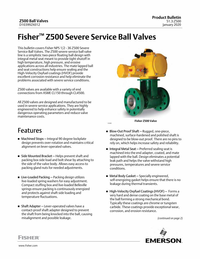
Table 14. Fisher Z500 Severe Service Ball Valve Raised-Face Flange Dimensions (in, lb)
PRESSURECLASS
VALVEBORESIZE
VALVESIZE
(NPS)
RAISED FACE FLANGED END CONNECTION (in, lb) Packing
A B C(1) J K L M P R S Weight Type BC T
150
0.65 0.75(4) 4.7 2.5 2.26 3.95 2.10 1.001/4 20
UNCN/A 0 0.38 18 I 1.88
1/4 20
UNC
1.15
1(4) 5.0 3.2 2.45 3.95 2.22 0.751/4 20
UNC0.3 0.315 0.75 25 II 2.25
1/4 20
UNC
1.5 6.5 3.2 2.50 4.0 2.90 0.751/4 20
UNC0.30 0.32 0.32 25 II 2.25
1/4 20
UNC
2 7.0 3.2 3.00 4.0 3.18 0.751/4 20
UNC0.30 0.32 0.32 30 II 2.25
1/4 20
UNC
1.5
1.5(3) 6.5 3.9 3.26 5.2 2.49 1.003/8 16
UNC.50 1.00 0.38 45 III 2.50
5/16 18
UNC
2 7.0 3.9 3.01 5.2 3.37 1.003/8 16
UNC0.50 1.00 0.38 45 III 2.50
5/16 18
UNC
2 2 7.0 4.6 3.25 5.2 3.52 0.753/8 16
UNC0.50 1.50 0.42 55 III 2.62
5/16 18
UNC
4 4(1)(3) 9.0 8.4 5.01 9.6 4.46 1.501/2 13
UNCN/A 1 0.50 180 I 3.50
7/16 14
UNC
6 6 15.5 11.1 6.96 13.6 7.52 2.003/4 10
UNCN/A 0.00 1.00 405 I 3.38
1/2 13
UNC
10 10 21.2 16.3 10.01 19.9 10.54 3.501/2 13
UNCN/A 0.00 1.53 1070 I 6.00
1/2 13
UNC
24 24(2) 42.1 42.0 22.11 16.0 21.78 5.001 1/4 8
UNCN/A 2.63 6.00 13550 I 10.38
3/4 10
UNC
300
0.65
0.5(3) 7.5 2.5 2.26 3.95 3.91 1.001/4 20
UNCN/A 0 0.38 25 I 1.88
1/4 20
UNC
0.75 6.0 2.5 2.31 4.0 2.55 1.001/4 20
UNCN/A 0.00 0.38 25 I 1.88
1/4 20
UNC
1 6.5 2.5 2.44 4.0 2.88 1.001/4 20
UNCN/A 0.00 0.38 25 I 1.88
1/4 20
UNC
1.5 7.5 2.5 3.06 4.0 3.20 1.001/4 20
UNCN/A 0.00 0.38 30 I 1.88
1/4 20
UNC
1.15
1 6.5 3.2 2.45 4.0 2.90 0.751/4 20
UNC0.30 0.32 0.32 25 II 2.25
1/4 20
UNC
1.5 7.5 3.2 3.06 4.0 3.45 0.751/4 20
UNC0.30 0.32 0.32 35 II 2.25
1/4 20
UNC
1.5
1.5 7.5 3.9 3.06 5.2 3.52 1.003/8 16
UNC0.50 1.00 0.38 50 III 2.50
5/16 18
UNC
2 8.5 3.9 3.25 5.2 3.52 1.003/8 16
UNC0.50 1.00 0.75 55 III 2.50
5/16 18
UNC
3 11.2 3.9 4.13 5.2 4.33 1.003/8 16
UNC0.50 1.00 0.75 80 III 2.50
5/16 18
UNC
2 2 8.5 4.6 3.25 5.5 4.18 0.753/8 16
UNC0.50 1.50 0.50 65 III 2.62
5/16 18
UNC
3
3 11.2 6.6 4.26 7.8 5.04 1.255/8 11
UNC0.62 1.38 0.60 135 III 2.75
3/8 16
UNC
4 12.0 6.6 5.00 7.8 5.42 1.255/8 11
UNC0.62 1.38 0.60 160 III 2.75
3/8 16
UNC
4 4 12.0 8.4 5.01 9.6 5.65 1.505/8 11
UNCN/A 1.00 0.75 195 I 3.50
7/16 14
UNC
6 6 15.9 11.1 6.96 13.6 7.90 2.003/4 10
UNCN/A 0.00 N/A 455 I 4.50
1/2 13
UNC
8 8 19.8 14.1 8.81 17.1 9.26 3.00 1 8 UNC N/A 0.00 1.50 870 I 5.007/16 14
UNC
-continued-

Z500 Ball ValvesD103992X012
Product Bulletin51.3:Z500January 2020
22
Table 14. Fisher Z500 Severe Service Ball Valve Raised-Face Flange Dimensions (in, lb) (cont.)
PRESSURECLASS
VALVEBORESIZE
VALVESIZE
(NPS)
RAISED FACE FLANGED END CONNECTION (in, lb) Packing
A B C(1) J K L M P R S Weight Type BC T
300
10 10 21.0 16.3 10.65 19.9 10.54 3.507/8 9
UNCN/A 0.00 1.38 1095 I 6.00
1/2 13
UNC
12 12 25.6 22.4 12.76 25.4 12.97 3.001 1/2 8
UNCN/A 0.00 2.51 2285 I 6.50
3/8 16
UNC
24 24(2) 45.1 42.0 22.26 43.8 23.35 5.001 5/8 8
UNCN/A 2.63 6.00 11860 I 10.38
3/4 10
UNC
600
0.65
0.5 6.5 2.5 1.88 4.0 2.77 1.001/4 20
UNCN/A 0.00 N/A 20 I 1.88
1/4 20
UNC
0.75 7.5 2.5 2.31 4.0 3.32 1.001/4 20
UNCN/A 0.00 N/A 25 I 1.88
1/4 20
UNC
1 8.5 2.5 2.44 4.0 3.82 1.001/4 20
UNCN/A 0.00 N/A 25 I 1.88
1/4 20
UNC
1.15
1 8.5 3.2 2.45 4.0 3.64 1.001/4 20
UNC0.30 0.32 0.50 30 II 2.25
1/4 20
UNC
1.5 9.5 3.2 3.06 4.0 4.14 1.001/4 20
UNC0.30 0.32 0.50 45 II 2.25
1/4 20
UNC
2 11.5 3.2 3.25 4.0 4.52 1.001/4 20
UNC0.30 0.32 0.50 50 II 2.25
1/4 20
UNC
1.5
1.5 9.5 3.9 3.06 5.2 3.99 1.003/8 16
UNC0.50 1.00 0.75 55 III 2.50
5/16 18
UNC
2 11.5 3.9 3.25 5.2 4.52 1.003/8 16
UNC0.50 1.00 0.75 65 III 2.50
5/16 18
UNC
3 14.0 3.9 4.13 5.2 5.77 1.003/8 16
UNC0.50 1.00 0.75 90 III 2.5
5/16 18
UNC
2
2 11.5 4.6 3.38 5.5 4.52 1.003/8 16
UNC0.50 1.50 1.00 105 III 2.62
5/16 18
UNC
3 14.0 4.6 4.13 5.5 5.77 1.003/8 16
UNC0.50 1.50 1.00 115 III 2.62
5/16 18
UNC
3
3 14.0 6.6 4.50 7.8 6.17 1.255/8 11
UNC0.62 1.38 0.85 165 III 2.75
3/8 16
UNC
4 17.0 6.6 5.38 7.8 7.92 1.255/8 11
UNC0.62 1.38 0.85 225 III 2.75
3/8 16
UNC
4 4 17.0 7.3 5.38 10.1 7.27 1.505/8 11
UNCN/A 0.00 1.75 280 I 3.50
7/16 14
UNC
6 6 22.0 10.3 7.26 14.4 10.25 2.007/8 9
UNCN/A 0.00 2.50 675 I 4.50
1/2 13
UNC
8 8 26.0 14.1 9.57 19.0 12.02 3.00 1 8 UNC N/A 0.00 1.88 1280 I 5.007/16 14
UNC
10 10 31.0 16.3 11.50 22.7 14.52 3.501 3/8 8
UNCN/A 0.00 2.50 2295 I 6.00
1/2 13
UNC
12 12 33.1 22.4 13.26 26.2 16.22 3.001 1/2 8
UNN/A 0.00 N/A 3615 I 6.88
3/8 16
UNC
14 14(2) 35.1 22.0 15.38 30.0 17.53 6.501 1/2 8
UNCN/A 2.00 3.75 4630 I 8.00
3/8 16
UNC
-continued-

Z500 Ball ValvesD103992X012
Product Bulletin51.3:Z500
January 2020
23
Table 14. Fisher Z500 Severe Service Ball Valve Raised-Face Flange Dimensions (in, lb) (cont.)
PRESSURECLASS
VALVEBORESIZE
VALVESIZE
(NPS)
RAISED FACE FLANGED END CONNECTION (in, lb) Packing
A B C(1) J K L M P R S Weight Type BC T
900
0.65
0.75 9.0 2.5 2.56 4.0 3.67 1.001/4 20
UNCN/A 0.00 0.45 35 I 1.88
1/4 20
UNC
1 10.3 2.5 2.96 4.0 4.17 1.001/4 20
UNCN/A 0.00 0.45 40 I 1.875
1/4 20
UNC
1.15
1 10.0 3.2 2.94 5.2 4.14 1.003/8 16
UNC0.00 0.37 0.38 50 II 2.25
1/4 20
UNC
2 14.5 3.2 4.27 4.0 5.69 1.003/8 16
UNC0.50 1.00 1.25 100 III 2.25
1/4 20
UNC
1.5
1.5 12.0 3.9 3.50 5.2 5.02 1.003/8 16
UNC0.50 1.00 0.75 85 III 2.50
5/16 18
UNC
2 14.5 3.9 4.25 5.2 6.27 1.003/8 16
UNC0.50 1.00 0.75 105 III 2.50
5/16 18
UNC
3 15.0 3.9 4.75 5.2 6.97 1.003/8 16
UNC0.50 1.00 0.75 135 III 2.50
5/16 18
UNC
2 2 14.5 4.6 4.25 5.5 5.86 1.003/8 16
UNC0.50 1.50 0.62 140 III 2.62
5/16 18
UNC
3 3 15.0 6.6 4.88 9.3 5.97 1.255/8 11
UNCN/A 0.00 1.50 215 I 2.75
3/8 16
UNC
4 4 18.0 8.4 5.75 11.6 7.45 2.503/4 10
UNCN/A 0.00 1.75 415 I 4.75
3/8 16
UNC
6
6 24.0 13.9 8.75 17.3 10.27 4.001 1/8 8
UNCN/A 0.00 1.75 1140 I 6.50
1/2 13
UNC
8 29.0 13.9 9.25 17.3 11.27 4.001 1/8 8
UNCN/A 0.00 1.75 1410 I 6.50
1/2 13
UNC
1500
0.65
0.75 9.0 2.5 2.56 4.0 3.67 1.001/4 20
UNCN/A 0.00 0.45 35 I 1.875
1/4 20
UNC
1 10.3 2.5 2.96 4.0 4.17 1.001/4 20
UNCN/A 0.00 0.45 40 I 1.875
1/4 20
UNC
1.15
1 10.0 3.2 2.94 5.2 4.14 1.003/8 16
UNC0.00 0.37 0.38 50 II 2.25
1/4 20
UNC
2 14.5 3.2 4.27 4.0 5.69 1.003/8 16
UNC0.50 1.00 1.25 100 III 2.25
1/4 20
UNC
1.5
1.5 12.0 3.9 3.50 5.2 5.02 1.003/8 16
UNC0.50 1.00 0.75 85 III 2.5
5/16 18
UNC
2 14.5 3.9 4.25 5.2 6.27 1.003/8 16
UNC0.50 1.00 0.75 105 III 2.5
5/16 18
UNC
2
2 14.5 4.6 4.25 5.5 5.86 1.003/8 16
UNC0.50 1.50 0.62 140 III 2.62
5/16 18
UNC
2.5 16.5 4.6 4.81 5.5 6.50 1.003/8 16
UNC0.50 1.50 0.62 160 III 2.62
5/16 18
UNC
3 18.5 4.6 5.25 5.8 7.61 1.003/8 16
UNC0.50 1.50 0.62 215 III 2.62
5/16 18
UNC
4 21.5 4.6 6.13 5.8 10.15 1.003/8 16
UNC0.50 1.50 0.62 270 III 2.62
5/16 18
UNC
3 3 18.5 7.8 5.70 10.3 7.77 1.753/4 10
UNCN/A 0.00 1.50 350 I 4.75
7/16 14
UNC
4 4 21.5 8.4 6.63 13.1 8.39 2.50 1 8 UNC N/A 0.00 2.38 590 I 4.753/8 16
UNC
8 8 32.8 16.2 11.01 21.7 13.46 4.131 1/4 8
UNCN/A 0.00 2.88 2395 I 7.12
1/2 13
UNC
-continued-
Z500 Ball ValvesD103992X012
Product Bulletin51.3:Z500January 2020
24
Table 14. Fisher Z500 Severe Service Ball Valve Raised-Face Flange Dimensions (in, lb) (cont.)
PRESSURECLASS
VALVEBORESIZE
VALVESIZE
(NPS)
RAISED FACE FLANGED END CONNECTION (in, lb) Packing
A B C(1) J K L M P R S Weight Type BC T
2500
1.15 1 12.2 3.5 3.13 5.5 4.70 1.003/8 16
UNCN/A 0.17 1.50 70 I 2.375
5/16 18
UNC
1.5 2 17.8 3.9 4.63 7.8 7.39 1.503/8 16
UNCN/A 0.00 2.00 210 I 4
3/8 16
UNC
2 4 26.5 5.3 7.00 7.6 12.27 1.001/2 13
UNC0.00 0.70 1.12 520 II 3.25
3/8 16
UNC
4 4 26.5 8.8 7.00 15.0 9.52 2.50 1 8 UNC N/A 0.00 3.50 1005 I 6.1255/8 11
UNC
Other sizes available, contact your Emerson sales office. 1. Uses the largest value of the body diameter or the flange diameter.2. Four bolt mounting bracket pattern instead of the standard two bolt pattern.3. Valve body and end adapter have blind threaded bolt hole connections.4. Valve body has blind threaded bolt hole connections.

Z500 Ball ValvesD103992X012
Product Bulletin51.3:Z500
January 2020
25
Table 15. Fisher Z500 Severe Service Ball Valve Raised-Face Flange Dimensions (mm, kg)
PRESSURECLASS
VALVEBORESIZE
VALVESIZE
(NPS)
RAISED FACE FLANGED END CONNECTION (mm, kg) Packing
A B C(1) J K L M P R S Weight Type BC T
150
0.65 0.75(4) 118.1 64.0 57.3 100.3 53.3 25.41/4 20
UNCN/A 0.0 9.5 8 I 47.6
1/4 20
UNC
1.15
1(4) 127.8 80.9 62.2 100.3 56.3 19.11/4 20
UNC7.6 8.0 19.1 11 II 57.2
1/4 20
UNC
1.5 165.9 80.9 63.5 100.3 73.5 19.11/4 20
UNC7.6 8.0 8.1 11 II 57.2
1/4 20
UNC
2 178.6 80.9 76.2 100.3 80.7 19.11/4 20
UNC7.6 8.0 8.1 14 II 57.2
1/4 20
UNC
1.5
1.5(3) 165.1 98.9 82.7 132.1 63.2 25.43/8 16
UNC12.7 25.4 9.5 20 III 63.5
5/16 18
UNC
2 178.6 98.9 76.4 132.1 85.7 25.43/8 16
UNC12.7 25.4 9.5 20 III 63.5
5/16 18
UNC
2 2 178.6 117.1 82.6 132.1 89.4 19.13/8 16
UNC12.7 38.1 10.7 25 III 66.5
5/16 18
UNC
4 4(1)(4) 229.4 213.0 127.2 243.8 113.2 38.11/2 13
UNCN/A 25.4 12.7 82 I 88.9
7/16 14
UNC
6 6 394.5 282.0 176.9 345.9 190.9 50.83/4 10
UNCN/A 0.0 25.4 184 I 85.9
1/2 13
UNC
10 10 538.0 412.8 254.2 505.5 267.7 88.91/2 13
UNCN/A 0.0 38.8 485 I 152.4
1/2 13
UNC
24 24(2) 1068.3 1066.0 561.6 406.4 553.2 127.01 1/4 8
UNCN/A 66.7 152.4 6146 I 263.5
3/4 10
UNC
300
0.65
0.5(3) 191.3 64.0 57.4 100.3 99.2 25.41/4 20
UNCN/A 0.0 9.5 11 I 47.6
1/4 20
UNC
0.75 153.2 64.0 58.7 100.3 64.8 25.41/4 20
UNCN/A 0.0 9.5 11 I 47.6
1/4 20
UNC
1 165.9 64.0 62.0 100.3 73.0 25.41/4 20
UNCN/A 0.0 9.5 11 I 47.6
1/4 20
UNC
1.5 191.3 64.0 77.7 100.3 81.3 25.41/4 20
UNCN/A 0.0 9.5 14 I 47.6
1/4 20
UNC
1.15
1 165.9 80.9 62.2 100.3 73.5 19.11/4 20
UNC7.6 8.0 8.1 11 II 57.2
1/4 20
UNC
1.5 191.3 80.9 77.7 100.3 87.5 19.11/4 20
UNC7.6 8.0 8.1 16 II 57.2
1/4 20
UNC
1.5
1.5 191.3 98.9 77.7 132.1 89.4 25.43/8 16
UNC12.7 25.4 9.5 23 III 63.5
5/16 18
UNC
2 216.7 98.9 82.6 132.1 89.3 25.43/8 16
UNC12.7 25.4 19.1 25 III 63.5
5/16 18
UNC
3 283.2 99.3 104.8 132.1 109.9 25.43/8 16
UNC12.7 25.4 19.1 36 III 63.5
5/16 18
UNC
2 2 216.7 117.1 82.6 139.7 106.1 19.13/8 16
UNC12.7 38.1 12.7 29 III 66.5
5/16 18
UNC
3
3 283.2 167.9 108.2 196.9 127.9 31.85/8 11
UNC15.7 34.9 15.2 61 III 69.9
3/8 16
UNC
4 305.6 167.9 127.0 196.9 137.5 31.85/8 11
UNC15.7 34.9 15.2 73 III 69.9
3/8 16
UNC
4 4 305.6 213.0 127.2 243.8 143.4 38.15/8 11
UNCN/A 25.4 19.1 88 I 88.9
7/16 14
UNC
6 6 404.1 282.0 176.9 345.9 200.5 50.83/4 10
UNCN/A 0.0 N/A 206 I 114.3
1/2 13
UNC
8 8 502.4 358.1 223.8 434.8 235.3 76.2 1 8 UNC N/A 0.0 38.2 395 I 127.07/16 14
UNC
-continued-

Z500 Ball ValvesD103992X012
Product Bulletin51.3:Z500January 2020
26
Table 15. Fisher Z500 Severe Service Ball Valve Raised-Face Flange Dimensions (mm, kg) (cont.)
PRESSURECLASS
VALVEBORESIZE
VALVESIZE
(NPS)
RAISED FACE FLANGED END CONNECTION (mm, kg) Packing
A B C(1) J K L M P R S Weight Type BC T
300
10 10 534.2 412.8 270.5 505.5 267.7 88.97/8 9
UNCN/A 0.0 35.0 497 I 152.4
1/2 13
UNC
12 12 649.2 567.7 324.1 645.2 329.3 76.21 1/2 8
UNCN/A 0.0 63.6 1036 I 165.1
3/8 16
UNC
24 24(2) 1144.5 1066.0 565.4 1112.5 593.1 127.01 5/8 8
UNCN/A 66.7 152.4 5380 I 263.5
3/4 10
UNC
600
0.65
0.5 165.9 64.0 47.6 100.3 70.2 25.41/4 20
UNCN/A 0.0 N/A 9 I 47.6
1/4 20
UNC
0.75 191.3 64.0 58.7 100.3 84.3 25.41/4 20
UNCN/A 0.0 N/A 11 I 47.6
1/4 20
UNC
1 216.7 64.0 62.0 100.3 97.0 25.41/4 20
UNCN/A 0.0 N/A 11 I 47.6
1/4 20
UNC
1.15
1 216.7 80.9 62.2 100.3 92.5 25.41/4 20
UNC7.6 8.0 12.7 14 II 57.2
1/4 20
UNC
1.5 242.1 80.9 77.7 100.3 105.2 25.41/4 20
UNC7.6 8.0 12.7 20 II 57.2
1/4 20
UNC
2 292.9 80.9 82.6 100.3 114.7 25.41/4 20
UNC7.6 8.0 12.7 23 II 57.2
1/4 20
UNC
1.5
1.5 242.1 98.9 77.7 132.1 101.3 25.43/8 16
UNC12.7 25.4 19.1 25 III 63.5
5/16 18
UNC
2 292.9 98.9 82.6 132.1 114.7 25.43/8 16
UNC12.7 25.4 19.1 29 III 63.5
5/16 18
UNC
3 356.4 98.9 104.8 132.1 146.4 25.43/8 16
UNC12.7 25.4 19.1 41 III 63.5
5/16 18
UNC
2
2 292.9 117.1 85.7 139.7 114.7 25.43/8 16
UNC12.7 38.1 25.4 48 III 66.5
5/16 18
UNC
3 356.4 117.1 104.8 139.7 146.4 25.43/8 16
UNC12.7 38.1 25.4 52 III 66.5
5/16 18
UNC
3
3 356.4 167.9 114.3 196.9 156.6 31.85/8 11
UNC15.7 34.9 21.6 75 III 69.9
3/8 16
UNC
4 432.6 167.9 136.5 196.9 201.0 31.85/8 11
UNC15.7 34.9 21.6 102 III 69.9
3/8 16
UNC
4 4 432.6 184.5 136.5 257.0 184.5 38.15/8 11
UNCN/A 0.0 44.5 127 I 88.9
7/16 14
UNC
6 6 559.6 260.4 184.4 365.8 260.4 50.87/8 9
UNCN/A 0.0 63.5 306 I 114.3
1/2 13
UNC
8 8 661.2 358.4 243.0 482.6 305.2 76.2 1 8 UNC N/A 0.0 47.6 581 I 127.07/16 14
UNC
10 10 788.2 412.8 292.1 576.6 368.7 88.91 3/8 8
UNCN/A 0.0 63.5 1041 I 152.4
1/2 13
UNC
12 12 839.7 567.7 336.8 665.5 411.9 76.21 1/2 8
UNN/A 0.0 N/A 1640 I 174.8
3/8 16
UNC
14 14(2) 890.5 558.4 390.7 762.0 445.3 165.11 1/2 8
UNCN/A 50.8 95.3 2100 I 203.2
3/8 16
UNC
900
0.65
0.75 229.4 64.0 65.0 100.3 93.1 25.41/4 20
UNCN/A 0.0 11.4 16 I 47.6
1/4 20
UNC
1 261.1 64.0 75.1 100.3 105.8 25.41/4 20
UNCN/A 0.0 11.4 18 I 47.6
1/4 20
UNC
1.15
1 254.8 80.9 74.7 101.6 105.2 25.43/8 16
UNC0.0 9.3 9.5 23 II 57.2
1/4 20
UNC
2 369.1 80.9 108.3 101.6 144.6 25.43/8 16
UNC12.7 25.4 31.8 45 III 57.2
1/4 20
UNC
-continued-

Z500 Ball ValvesD103992X012
Product Bulletin51.3:Z500
January 2020
27
Table 15. Fisher Z500 Severe Service Ball Valve Raised-Face Flange Dimensions (mm, kg) (cont.)
PRESSURECLASS
VALVEBORESIZE
VALVESIZE
(NPS)
RAISED FACE FLANGED END CONNECTION (mm, kg) Packing
A B C(1) J K L M P R S Weight Type BC T
900
1.5
1.5 305.6 98.9 88.9 132.1 127.4 25.43/8 16
UNC12.7 25.4 19.1 39 III 63.5
5/16 18
UNC
2 369.1 98.9 108.0 132.1 159.1 25.43/8 16
UNC12.7 25.4 19.1 48 III 63.5
5/16 18
UNC
3 381.8 99.3 120.7 132.1 176.9 25.43/8 16
UNC12.7 25.4 19.1 61 III 63.5
5/16 18
UNC
2 2 369.1 117.1 108.0 139.7 148.8 25.43/8 16
UNC12.7 38.1 15.7 64 III 66.5
5/16 18
UNC
3 3 381.8 167.9 123.8 235.0 151.5 31.85/8 11
UNCN/A 0.0 38.1 98 I 69.9
3/8 16
UNC
4 4 458.0 213.8 146.1 295.1 189.3 63.53/4 10
UNCN/A 0.0 44.5 188 I 120.7
3/8 16
UNC
6
6 610.4 352.5 222.3 438.2 260.7 101.61 1/8 8
UNCN/A 0.0 44.5 517 I 165.1
1/2 13
UNC
8 737.4 352.5 235.0 438.2 286.1 101.61 1/8 8
UNCN/A 0.0 44.5 640 I 165.1
1/2 13
UNC
1500
0.65
0.75 229.4 64.0 65.0 100.3 93.1 25.41/4 20
UNCN/A 0.0 11.4 16 I 47.6
1/4 20
UNC
1 261.1 64.0 75.1 100.3 105.8 25.41/4 20
UNCN/A 0.0 11.4 18 I 47.6
1/4 20
UNC
1.15
1 254.8 80.9 74.7 132.1 105.2 25.43/8 16
UNC0.0 9.3 9.5 23 II 57.2
1/4 20
UNC
2 369.1 80.9 108.3 101.6 144.6 25.43/8 16
UNC12.7 25.4 31.8 45 III 57.2
1/4 20
UNC
1.5
1.5 305.6 98.9 88.9 132.1 127.4 25.43/8 16
UNC12.7 25.4 19.1 39 III 63.5
5/16 18
UNC
2 369.1 98.9 108.0 132.1 159.1 25.43/8 16
UNC12.7 25.4 19.1 48 III 63.5
5/16 18
UNC
2
2 369.1 117.1 108.0 139.7 148.8 25.43/8 16
UNC12.7 38.1 15.7 64 III 66.5
5/16 18
UNC
2.5 419.9 117.1 122.2 139.7 165.1 25.43/8 16
UNC12.7 38.1 15.7 73 III 66.5
5/16 18
UNC
3 470.7 117.1 133.4 146.1 193.3 25.43/8 16
UNC12.7 38.1 15.7 98 III 66.5
5/16 18
UNC
4 546.9 117.1 155.6 146.1 257.8 25.43/8 16
UNC12.7 38.1 15.7 122 III 66.5
5/16 18
UNC
3 3 470.7 197.2 144.7 260.4 197.2 44.53/4 10
UNCN/A 0.0 38.1 159 I 120.7
7/16 14
UNC
4 4 546.9 213.8 168.5 332.7 213.1 63.5 1 8 UNC N/A 0.0 60.3 268 I 120.73/8 16
UNC
8 8 832.6 410.5 279.6 551.2 341.8 104.81 1/4 8
UNCN/A 0.0 73.0 1086 I 180.8
1/2 13
UNC
2500
1.15 1 308.6 88.8 79.4 139.7 119.4 25.43/8 16
UNCN/A 4.3 38.1 32 I 60.3
5/16 18
UNC
1.5 2 451.6 99.8 117.5 196.9 187.6 38.13/8 16
UNCN/A 0.0 50.8 95 I 101.6
3/8 16
UNC
2 4 673.9 135.8 177.8 193.7 311.5 25.41/2 13
UNC0.0 17.8 28.4 236 II 82.6
3/8 16
UNC
4 4 673.9 224.6 177.8 381.0 241.7 63.5 1 8 UNC N/A 0.0 88.9 456 I 155.65/8 11
UNC
Other sizes available, contact your Emerson sales office. 1. Uses the largest value of the body diameter or the flange diameter.2. Four bolt mounting bracket pattern instead of the standard two bolt pattern.3. Valve body and end adapter have blind threaded bolt hole connections4. Valve body has blind threaded bolt hole connections.

Z500 Ball ValvesD103992X012
Product Bulletin51.3:Z500January 2020
28
Table 16. Fisher Z500 Severe Service Ball Valve Ring-Type Joint End Connection, Face-to-Face Dimensions(ASME B16.10)
ValveSize, NPS
CL150 CL300 CL600 CL900 CL1500 CL2500
mm Inches mm Inches mm Inches mm Inches mm Inches mm Inches
0.5 - - - - - - 150.9 5.94 163.6 6.44 - - - - - - - - - - - - - - - - - -
0.75 - - - - - - 165.1 6.5 190.5 7.5 - - - - - - - - - - - - - - - - - -
1 139.7 5.5 177.8 7 215.9 8.5 254 10 - - - - - - - - - - - -
1.5 177.8 7 203.2 8 241.3 9.5 305 12 - - - - - - - - - - - -
2 190.5 7.5 231.6 9.12 295.1 11.6 371 14.6 371 14.62 454 17.87
2.5 203.2 8 257 10.12 333.2 13.1 422 16.6 422 16.62 514 20.25
3 215.9 8.5 298.2 11.74 358.6 14.1 384 15.1 473 18.62 584 23
4 241.3 9.5 320.5 12.62 434.8 17.1 460 18.1 549 21.62 683 26.88
6 279.4 11 419.1 16.5 561.8 22.1 613 24.1 711 28 927 36.5
8 304.8 12 517.4 20.37 663.4 26.1 740 29.1 842 33.13 1038 40.87
10 342.9 13.5 584.2 23 790.4 31.1 841 33.1 1000.3 39.38 1292 50.88
12 368.3 14.5 663.4 26.12 841.2 33.1 968 38.1 1146.0 45.12 1445 56.88
Figure 9. Fisher Z500 Shaft Dimensions (see tables 17 and 18)
E
F
DOUBLE D SHAFTKEYED SHAFT
E1781
G
H
E
H
F

Z500 Ball ValvesD103992X012
Product Bulletin51.3:Z500
January 2020
29
Table 17. Fisher Z500 Severe Service Ball Valve Shaft Dimensions (in)
PRESSURE CLASS VALVE BORE SIZEDouble D Key
H EF G
CL150
0.65 0.450 0.410 0.191 0.515 0.625
1.15 0.550 0.539 0.191 0.642 0.750
1.5 0.600 0.719 0.253 1.015 1.000
2 0.840 0.848 0.253 1.015 1.125
3 1.125 1.079 0.378 1.515 1.500
4 - - - 1.437 0.503 2.015 2.000
6 - - - 1.786 0.627 2.515 2.491
8 - - - 2.155 0.751 4.145 3.000
10 - - - 2.873 1.003 4.015 4.000
14 - - - 3.587 1.252 5.641 5.000
24 - - - 5.746 2.001 8.515 8.000
CL300
0.65 0.450 0.410 0.191 0.515 0.625
1.15 0.550 0.539 0.191 0.642 0.750
1.5 0.600 0.719 0.253 1.015 1.000
2 0.840 0.848 0.253 1.015 1.125
3 1.125 1.079 0.378 1.515 1.500
4 - - - 1.437 0.503 2.015 2.000
6 - - - 1.786 0.627 2.515 2.491
8 - - - 2.155 0.751 4.145 3.000
10 - - - 2.873 1.003 4.015 4.000
14 - - - 3.587 1.252 5.641 5.000
24 - - - 5.746 2.001 8.515 8.000
CL600
0.65 0.450 0.410 0.191 0.515 0.625
1.15 0.550 0.539 0.191 0.642 0.750
1.5 0.600 0.719 0.253 1.015 1.000
2 0.840 0.848 0.253 1.015 1.125
3 1.125 1.079 0.378 1.515 1.500
4 - - - 1.437 0.503 2.015 2.000
6 - - - 1.786 0.627 2.515 2.491
8 - - - 2.155 0.751 4.145 3.000
10 - - - 2.873 1.003 4.015 4.000
14 - - - 3.587 1.252 5.641 5.000
CL900
0.65 0.450 0.410 0.191 0.515 0.625
1.15 0.550 0.539 0.191 0.642 0.750
1.5 0.600 0.719 0.253 1.015 1.000
2 0.840 0.848 0.253 1.015 1.125
3 1.125 1.079 0.378 1.515 1.500
4 - - - 1.797 0.628 2.265 2.500
6 - - - 2.413 0.753 3.515 3.250
CL1500
0.65 0.450 0.410 0.191 0.515 0.625
1.15 0.550 0.539 0.191 0.642 0.750
1.5 0.600 0.719 0.253 1.015 1.000
2 0.840 0.848 0.253 1.015 1.125
3 1.500 1.437 0.503 .765 2.000
4 - - - 1.797 0.628 2.265 2.500
6 - - - 2.413 0.753 3.515 3.250
8 - - - 2.744 1.003 6.025 3.875
‐continued‐

Z500 Ball ValvesD103992X012
Product Bulletin51.3:Z500January 2020
30
Table 17. Fisher Z500 Severe Service Ball Valve Shaft Dimensions (in) (cont.)
PRESSURE CLASS VALVE BORE SIZEDouble D Key
H EF G
CL2500
0.65 0.450 0.410 0.191 0.515 0.625
1.15 0.550 0.539 0.191 0.642 0.750
1.5 0.750 0.719 0.253 0.936 1.000
2 0.866 0.975 0.253 1.016 1.250
3 - - - 1.437 0.503 1.765 2.000
4 - - - 1.796 0.628 2.265 2.500
6 - - - 2.413 0.753 3.515 3.250
CL3200
0.65 0.450 0.410 0.191 0.515 0.625
1.15 0.580 - - - - - - 0.640 0.750
1.5 0.750 0.719 0.253 0.936 1.000
2 0.866 0.975 0.253 1.235 1.250
CL4500
0.65 0.550 0.539 0.191 0.471 0.750
1.15 0.650 0.668 0.191 0.642 0.875
1.5 0.840 0.848 0.253 0.877 1.125

Z500 Ball ValvesD103992X012
Product Bulletin51.3:Z500
January 2020
31
Table 18. Fisher Z500 Severe Service Ball Valve Shaft Dimensions (mm)
PRESSURE CLASS VALVE BORE SIZEDouble D Key
H EF G
CL150
0.65 11.4 10.4 4.9 13.1 15.9
1.15 14.0 13.7 4.9 16.3 19.1
1.5 15.2 18.3 6.4 25.8 25.4
2 21.3 21.5 6.4 25.8 28.6
3 28.6 27.4 9.6 38.5 38.1
4 - - - 36.5 12.8 51.2 50.8
6 - - - 45.4 15.9 63.9 63.3
8 - - - 54.7 19.1 105.3 76.2
10 - - - 73.0 25.5 102.0 101.6
14 - - - 91.1 31.8 143.3 127.0
24 - - - 145.9 50.8 216.3 203.2
CL300
0.65 11.4 10.4 4.9 13.1 15.9
1.15 14.0 13.7 4.9 16.3 19.1
1.5 15.2 18.3 6.4 25.8 25.4
2 21.3 21.5 6.4 25.8 28.6
3 28.6 27.4 9.6 38.5 38.1
4 - - - 36.5 12.8 51.2 50.8
6 - - - 45.4 15.9 63.9 63.3
8 - - - 54.7 19.1 105.3 76.2
10 - - - 73.0 25.5 102.0 101.6
14 - - - 91.1 31.8 143.3 127.0
24 - - - 145.9 50.8 216.3 203.2
CL600
0.65 11.4 10.4 4.9 13.1 15.9
1.15 14.0 13.7 4.9 16.3 19.1
1.5 15.2 18.3 6.4 25.8 25.4
2 21.3 21.5 6.4 25.8 28.6
3 28.6 27.4 9.6 38.5 38.1
4 - - - 36.5 12.8 51.2 50.8
6 - - - 45.4 15.9 63.9 63.3
8 - - - 54.7 19.1 105.3 76.2
10 - - - 73.0 25.5 102.0 101.6
14 - - - 91.1 31.8 143.3 127.0
CL900
0.65 11.4 10.4 4.9 13.1 15.9
1.15 14.0 13.7 4.9 16.3 19.1
1.5 15.2 18.3 6.4 25.8 25.4
2 21.3 21.5 6.4 25.8 28.6
3 28.6 27.4 9.6 38.5 38.1
4 - - - 45.6 16.0 57.5 63.5
6 - - - 61.3 19.1 89.3 82.6
CL1500
0.65 11.4 10.4 4.9 13.1 15.9
1.15 14.0 13.7 4.9 16.3 19.1
1.5 15.2 18.3 6.4 25.8 25.4
2 21.3 21.5 6.4 25.8 28.6
3 38.1 36.5 12.8 44.8 50.8
4 - - - 45.6 16.0 57.5 63.5
6 - - - 61.3 19.1 89.3 82.6
8 - - - 69.7 25.5 153.0 98.4
‐continued‐

Z500 Ball ValvesD103992X012
Product Bulletin51.3:Z500January 2020
32
Table 18. Fisher Z500 Severe Service Ball Valve Shaft Dimensions (mm) (cont.)
PRESSURE CLASS VALVE BORE SIZEDouble D Key
H EF G
CL2500
0.65 11.4 10.4 4.9 13.1 15.9
1.15 14.0 13.7 4.9 16.3 19.1
1.5 19.1 18.3 6.4 23.8 25.4
2 22.0 24.8 6.4 25.8 31.8
3 - - - 36.5 12.8 44.8 50.8
4 - - - 45.6 16.0 57.5 63.5
6 - - - 61.3 19.1 89.3 82.6
CL3200
0.65 11.4 10.4 4.9 13.1 15.9
1.15 14.7 - - - - - - 16.3 19.1
1.5 19.1 18.3 6.4 23.8 25.4
2 22.0 24.8 6.4 31.4 31.8
CL4500
0.65 14.0 13.7 4.9 12.0 19.1
1.15 16.5 17.0 4.9 16.3 22.2
1.5 21.3 21.5 6.4 22.3 28.6
Emerson Automation SolutionsMarshalltown, Iowa 50158 USASorocaba, 18087 BrazilCernay, 68700 FranceDubai, United Arab EmiratesSingapore 128461 Singapore
www.Fisher.com
The contents of this publication are presented for informational purposes only, and while every effort has been made to ensure their accuracy, they are notto be construed as warranties or guarantees, express or implied, regarding the products or services described herein or their use or applicability. All sales aregoverned by our terms and conditions, which are available upon request. We reserve the right to modify or improve the designs or specifications of suchproducts at any time without notice.
� 2015, 2020 Fisher Controls International LLC. All rights reserved.
Fisher is a mark owned by one of the companies in the Emerson Automation Solutions business unit of Emerson Electric Co. Emerson Automation Solutions,Emerson, and the Emerson logo are trademarks and service marks of Emerson Electric Co. All other marks are the property of their respective owners.
Neither Emerson, Emerson Automation Solutions, nor any of their affiliated entities assumes responsibility for the selection, use or maintenanceof any product. Responsibility for proper selection, use, and maintenance of any product remains solely with the purchaser and end user.


![Surface & Coatings Technology - UNIQUECOAT … of HVOF- and HVAF-spray… · 8–11], the process parameters [10,13], the properties of the carbide (WC- or Cr 3C 2-based) and the](https://img.pdfslide.us/doc/110x75/5a9f181f7f8b9a7f178c59e8/surface-coatings-technology-uniquecoat-of-hvof-and-hvaf-spray811.jpg)