Embed Size (px)
Citation preview
Surface & Coatings Technology 210 (2012) 15–20
Contents lists available at SciVerse ScienceDirect
Surface & Coatings Technology
j ourna l homepage: www.e lsev ie r .com/ locate /sur fcoat
Wear properties of CrC–37WC–18M coatings deposited by HVOF and HVAFspraying processes
I. Hulka a, V.A. Şerban a, I. Secoşan a, P. Vuoristo b,⁎, K. Niemi b
a Department of Materials and Welding Science “Politehnica” University of Timişoara, Blv. Mihai Viteazu, No 1, RO-300222, Romaniab Department of Materials Science, Tampere University of Technology, Korkeakoulunkatu 6, FI-33101 Finland
⁎ Corresponding author. Tel.: +358 40 849 0044; faxE-mail addresses: [email protected] (I. Hulka),
(V.A. Şerban), [email protected] (I. Secoşan), p(P. Vuoristo), [email protected] (K. Niemi).
0257-8972/$ – see front matter © 2012 Elsevier B.V. Allhttp://dx.doi.org/10.1016/j.surfcoat.2012.07.077
a b s t r a c t
a r t i c l e i n f oArticle history:Received 30 March 2012Accepted in revised form 29 July 2012Available online 4 August 2012
Keywords:CrC–37WC–18MHVOFHVAFWear
CrC–37WC–18M cermet coatings were deposited using new feedstock powders which seem to combine theproperties of WC–CoCr and CrC–NiCr coatings. A conventional particle size CrC–37WC–18M powder wasused as feedstock for the HVOF (high velocity oxygen fuel) thermal spraying process and a fine particle dis-tribution was used as feedstock for the HVAF (high velocity air fuel) thermal spraying process. In order tocharacterize the morphology of the feedstock powders and deposited coatings SEM and X-ray diffractionwere used. The microhardness of the coatings was also studied. The wear behavior of the coatings was eval-uated by pin-on-disk and rubber wheel abrasion tests. The HVAF coating showed equal or even better wearresistance as compared to corresponding HVOF coatings.
© 2012 Elsevier B.V. All rights reserved.
1. Introduction
Thermal sprayedWC cermet coatings have been used to resist wearenvironments at ambient and elevated temperatures for a number ofyears due to their properties such as high abrasion, sliding and erosionresistance, advantages offered by dense coatings [1,2]. High velocityoxygen fuel (HVOF) thermal spraying is suitable in obtaining dense cer-met coatings with low oxidation due to its unique advantage of heatingthe feedstock to near or above itsmelting point, preferably between thesolidus and liquidus temperatures, at a relatively low process tempera-ture by a supersonic combustion gas stream [3–5]. Due to high velocity,the time of interaction between the powder and the flame shortens andin conjunction with the process temperature limited thermal alterationoccurs ensuring good cohesion and morphology with reduced porosityand low decarburization [6,7]. An alternative to the HVOF process, formanufacturing cermet hard coatings, is the high velocity air fuel(HVAF) process which utilizes compressed air, instead of oxygen, forcombustion and operates at lower temperatures than the HVOF process[8]. The HVAF process reduces the manufacturing cost of coatings, re-placing pure oxygen by compressed air having as consequence coatingswhich do not show any of the oxidation or decarburization effectsafter spraying [9]. WC and CrxCy based thermally sprayed coatings areextensively used to decrease the friction coefficient between varioussliding components and to improve corrosion resistance inmany indus-tries [10,11]. Due to the Cr content the coatings are suitable for
: +358 3 3115 [email protected]@tut.fi
rights reserved.
high-temperature applications [12]. The CrC–37WC–18M is quite anew powder developed to combine the properties of WC–CoCr andCrC–NiCr cermet powders. It is composed of two carbide phases WCand Cr3C2 embedded into an alloy composed of Ni, Co and a smallamount of Fe. There are no studies in the literature focused on the prop-erties of CrC–37WC–18M deposited via HVOF and HVAF processes. Theaim of the study was to characterize the phase and microstructure ofthe CrC–37WC–18M coatings deposited by HVAF and HVOF thermalspraying as well as to study the composition, abrasive and slidingwear behaviors of the coatings.
2. Experimental
Two types of CrC–37WC–18M powders were used for this study: aWOKA 7502 powder with a nominal size distribution of−45+15 μmand a fine WOKA 7504 powder with a nominal size distribution of−30+10 μm. Both powders are manufactured by Sulzer Metco,Germany, by agglomeration and sintering. A Sympatec Helos laser dif-fractometer was used to determine the particle size distribution of thepowders. Philips XL-30 scanning electron microscope equipped withan EDAX analyzer was used to investigate the morphology of thepowders and coatings in this study.WOKA 7504 powder was depositedby the HVAF process using a M2 thermal spray gun with 0.52[MPa]propane, respectively and [0.59]MPa air as process gases. The standoffdistance was 150 mm. WOKA 7502 powder was deposited by the HVOFprocess using a Diamond Jet Hybrid 2700 gun at TUT with 68 l/min pro-pane, 236 l/min oxygen and 368 l/min air as process gases. The standoffdistance was 230 mm, traverse speed of the gun 11 mm/s and powderfeed rate 60 g/min. This gun provides particle velocities up to 650 m/s.In both processes nitrogen was used as a carrier gas for the feedstock
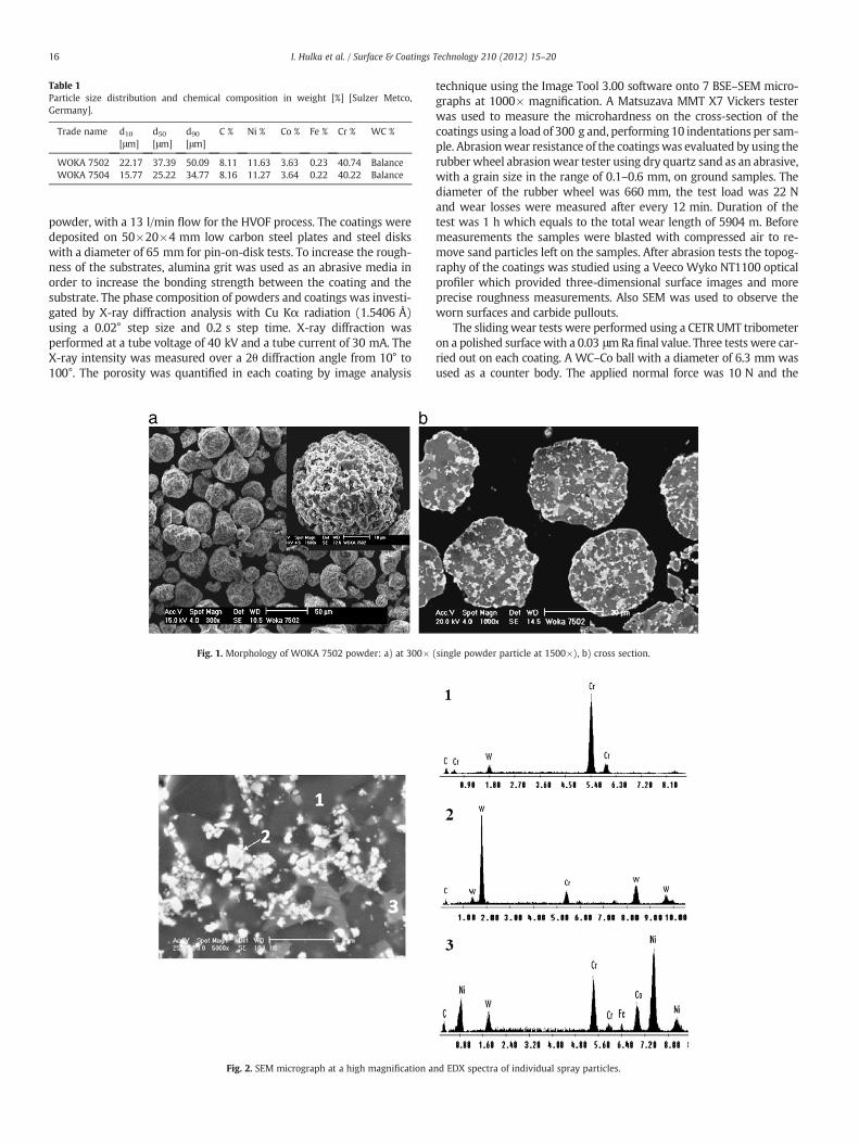
Table 1Particle size distribution and chemical composition in weight [%] [Sulzer Metco,Germany].
Trade name d10
[μm]d50
[μm]d90
[μm]C % Ni % Co % Fe % Cr % WC %
WOKA 7502 22.17 37.39 50.09 8.11 11.63 3.63 0.23 40.74 BalanceWOKA 7504 15.77 25.22 34.77 8.16 11.27 3.64 0.22 40.22 Balance
16 I. Hulka et al. / Surface & Coatings Technology 210 (2012) 15–20
powder, with a 13 l/min flow for the HVOF process. The coatings weredeposited on 50×20×4 mm low carbon steel plates and steel diskswith a diameter of 65 mm for pin-on-disk tests. To increase the rough-ness of the substrates, alumina grit was used as an abrasive media inorder to increase the bonding strength between the coating and thesubstrate. The phase composition of powders and coatings was investi-gated by X-ray diffraction analysis with Cu Kα radiation (1.5406 Å)using a 0.02° step size and 0.2 s step time. X-ray diffraction wasperformed at a tube voltage of 40 kV and a tube current of 30 mA. TheX-ray intensity was measured over a 2θ diffraction angle from 10° to100°. The porosity was quantified in each coating by image analysis
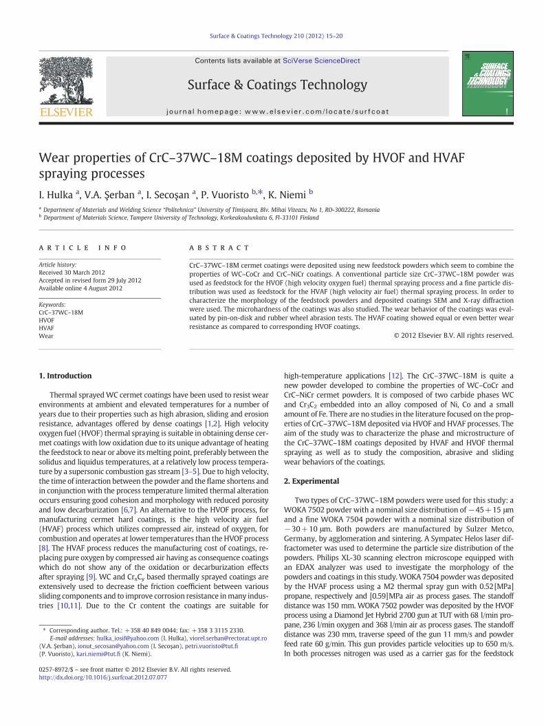
Fig. 1. Morphology of WOKA 7502 powder: a) at 300×
Fig. 2. SEM micrograph at a high magnification a
technique using the Image Tool 3.00 software onto 7 BSE–SEM micro-graphs at 1000× magnification. A Matsuzava MMT X7 Vickers testerwas used to measure the microhardness on the cross-section of thecoatings using a load of 300 g and, performing 10 indentations per sam-ple. Abrasionwear resistance of the coatingswas evaluated by using therubberwheel abrasionwear tester using dry quartz sand as an abrasive,with a grain size in the range of 0.1–0.6 mm, on ground samples. Thediameter of the rubber wheel was 660 mm, the test load was 22 Nand wear losses were measured after every 12 min. Duration of thetest was 1 h which equals to the total wear length of 5904 m. Beforemeasurements the samples were blasted with compressed air to re-move sand particles left on the samples. After abrasion tests the topog-raphy of the coatings was studied using a Veeco Wyko NT1100 opticalprofiler which provided three-dimensional surface images and moreprecise roughness measurements. Also SEM was used to observe theworn surfaces and carbide pullouts.
The slidingwear tests were performed using a CETR UMT tribometeron a polished surfacewith a 0.03 μmRa final value. Three tests were car-ried out on each coating. A WC–Co ball with a diameter of 6.3 mm wasused as a counter body. The applied normal force was 10 N and the
(single powder particle at 1500×), b) cross section.
nd EDX spectra of individual spray particles.
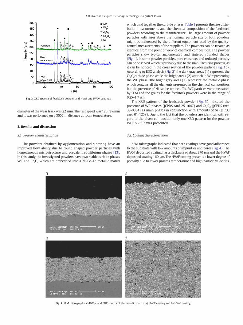
Fig. 3. XRD spectra of feedstock powder, and HVAF and HVOF coatings.
17I. Hulka et al. / Surface & Coatings Technology 210 (2012) 15–20
diameter of the wear track was 22 mm. The test speed was 120 rev/minand it was performed on a 3000 m distance at room temperature.
3. Results and discussion
3.1. Powder characterization
The powders obtained by agglomeration and sintering have animproved flow ability due to round shaped powder particles withhomogeneous microstructure and prevalent equilibrium phases [13].In this study the investigated powders have two stable carbide phasesWC and Cr2C3 which are embedded into a Ni–Co–Fe metallic matrix
Fig. 4. SEM micrographs at 4000× and EDX spectra of the m
which bind together the carbide phases. Table 1 presents the size distri-bution measurements and the chemical composition of the feedstockpowders according to the manufacturer. The large amount of powderparticles with sizes above the nominal particle size of both powdersmight be influenced by the different equipment used by the quality-control measurements of the suppliers. The powders can be treated asidentical from the point of view of chemical composition. The powderparticles show typical agglomerated and sintered rounded shapes(Fig. 1). In some powder particles, pore entrances and reduced porositycan be observedwhich is probably due to themanufacturing process, asit can be noticed in the cross section of the powder particle (Fig. 1b).According to EDX analysis (Fig. 2) the dark gray areas (1) represent theCr3C2carbide phase while the bright areas (2) are rich inW representingthe WC phase. The bright gray areas (3) represent the metallic phasewhich contains all the elements presented in the chemical composition,but the presence of Ni can be noticed. The WC particles were measuredby SEM and the grains for the feedstock powders were in the range of0.25–1.7 μm.
The XRD pattern of the feedstock powder (Fig. 3) indicated thepresence of WC phases (JCPDS card 25‐1047) and Cr3C2 (JCPDS card35‐0804) as main phases in conjunction with amounts of Ni (JCPDScard 01‐1258). Due to the fact that the powders are identical with re-gard to the phase composition only one XRD pattern for the powderWOKA 7502 was presented.
3.2. Coating characterization
SEMmicrographs indicated that both coatings have good adherenceto the substrate with low amounts of impurities and pores (Fig. 4). TheHVOF deposited coating has a thickness of about 270 μm and the HVAFdeposited coating 160 μm. The HVAF coating presents a lower degree ofporosity due to lower process temperature and high particle velocities.
etallic matrix: a) HVOF coating and b) HVAF coating.
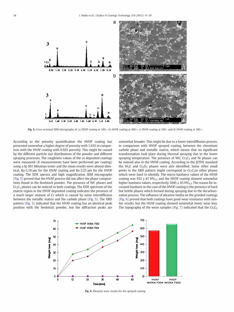
Fig. 5. Cross sectional SEM micrographs of: a) HVOF coating at 100×, b) HVOF coating at 300×, c) HVAF coating at 100× and d) HVAF coating at 300×.
18 I. Hulka et al. / Surface & Coatings Technology 210 (2012) 15–20
According to the porosity quantification the HVOF coating haspresented somewhat a higher degree of porosity with 1.63% in compar-ison with the HVAF coating with 0.92% porosity. This might be causedby the different particle size distributions of the powder and differentspraying processes. The roughness values of the as deposited coatingswere measured (8 measurements have been performed per coating)using a SJ-301 Mitutoyo tester and the mean results were almost iden-tical, Ra-5.18 μm for the HVAF coating and Ra-5.25 μm for the HVOFcoating. The EDX spectra and high magnification SEM micrographs(Fig. 5) proved that the HVAF process did not affect the phase composi-tions found in the feedstock powder. The presence of WC phases andCr2C3 phases can be noticed in both coatings. The EDX spectrum of thematrix region in the HVOF deposited coating indicates the presence ofa much larger amount of Cr which is caused by some interdiffusionbetween the metallic matrix and the carbide phase (Fig. 5). The XRDpattern (Fig. 3) indicated that the HVAF coating has an identical peakposition with the feedstock powder, but the diffraction peaks are
Fig. 6. Abrasion wear results
somewhat broader. This might be due to a lower interdiffusion process,in comparison with HVOF sprayed coating, between the chromiumcarbide phase and metallic matrix, which means that no significanttransformation took place during thermal spraying due to the lowerspraying temperature. The presence of WC, Cr3C2 and Ni phases canbe noticed also in the HVOF coating. According to the JCPDS standardthe W2C and Cr2O3 phases were also identified. Some other smallpeeks in the XRD pattern might correspond to Cr7C3or other phaseswhich were hard to identify. The micro-hardness values of the HVAFcoating was 932±47 HV0.3 and the HVOF coating showed somewhathigher hardness values, respectively 1045±65 HV0.3. The reason for in-creased hardness in the case of the HVOF coating is the presence of hardbut brittle phases which formed during spraying due to the decarburi-zation process. The influence of abrasive media on the grinded coatings(Fig. 6) proved that both coatings have good wear resistance with sim-ilar results, but the HVAF coating showed somewhat lower wear loss.The topography of the worn samples (Fig. 7) indicated that the Cr3C2
for the sprayed coating.
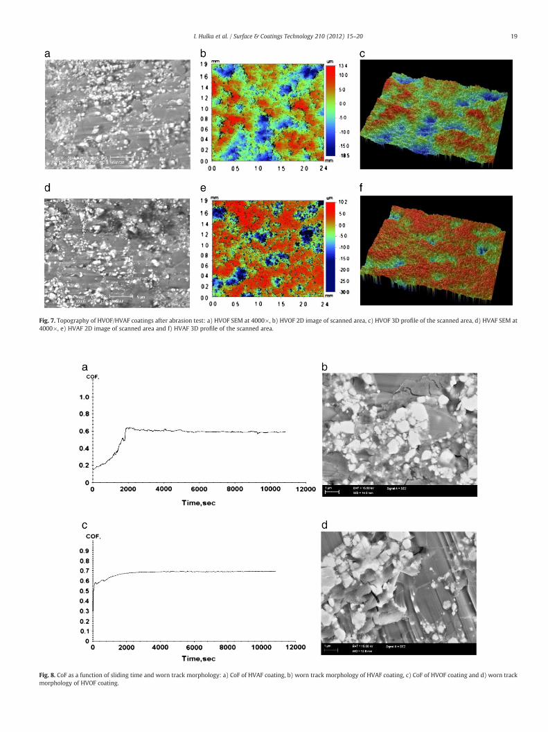
Fig. 7. Topography of HVOF/HVAF coatings after abrasion test: a) HVOF SEM at 4000×, b) HVOF 2D image of scanned area, c) HVOF 3D profile of the scanned area, d) HVAF SEM at4000×, e) HVAF 2D image of scanned area and f) HVAF 3D profile of the scanned area.
Fig. 8. CoF as a function of sliding time and worn track morphology: a) CoF of HVAF coating, b) worn track morphology of HVAF coating, c) CoF of HVOF coating and d) worn trackmorphology of HVOF coating.
19I. Hulka et al. / Surface & Coatings Technology 210 (2012) 15–20
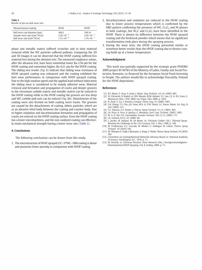
Table 2Results of pin-on-disk wear test.
Measurements/coating HVAF HVOF
Ball worn cap diameter [μm] 384.2 760.16Sample wear rate [mm3/N/m] 2.26∗10−5 2.62∗10−5
Ball wear rate [mm3/N/m] 1.13∗10−8 1.74∗10−7
20 I. Hulka et al. / Surface & Coatings Technology 210 (2012) 15–20
phase and metallic matrix suffered scratches and in time materialremoval while the WC particles suffered pullouts. Comparing the 2Dand 3D images it can be observed that the HVAF coating suffered lessmaterial loss during the abrasion test. The measured roughness values,after the abrasion test, have been somewhat lower Ra-3.56 μm for theHVAF coating and somewhat higher, Ra-4.21 μm for the HVOF coating.The sliding test results (Fig. 8) indicate that sliding wear resistance ofHVAF sprayed coating was enhanced and the coating exhibited thebest wear performance in comparison with HVOF sprayed coating.Due to the high rotation speed and the applied loadwithout lubricationthe sliding wear is considered to be mainly adhesive wear. Materialremoval and formation and propagation of cracks and deeper groovesin the chromium carbide matrix and metallic matrix can be noticed inthe HVOF coating while in the HVAF coating the grooves are less deepand WC carbide pull outs can be noticed (Fig. 8b). Detachments of thecoating were also formed on both coating worn tracks. The groovesare caused by the detachments of coating, debris particles, which actas an abrasive third body between the coating and counter body. Dueto higher oxidation and decarburization formation and propagation ofcracks are noticed on the HVOF coating surface. Even the HVAF coatinghas a lower microhardness, and the non-oxidized coating can effective-ly retain mechanical strength having a lower wear rate (Table 2).
4. Conclusions
The following conclusions can be drawn from this study:
1. Themicrostructure of HVAF sprayed CrC–37WC–18Mcoating is denseand possesses lower porosity in comparison with HVOF coating.
2. Decarburization and oxidation are reduced in the HVAF coatingdue to lower process temperatures which is confirmed by theXRD pattern confirming the presence of WC, Cr3C2 and Ni phasesin both coatings, but W2C and Cr2O3 have been identified in theHVOF. There is almost no difference between the HVAF sprayedcoating and the feedstock powder which means that no significanttransformation took place during the spraying process.
3. During the wear tests, the HVAF coating presented similar orsomehow better results than the HVOF coating due to denser coat-ing build up at a lower temperature.
Acknowledgment
This work was partially supported by the strategic grant POSDRU2009 project ID 50783 of the Ministry of Labor, Family and Social Pro-tection, Romania, co-financed by the European Social Fund-Investingin People. The authors would like to acknowledge FincoatOy, Finlandfor the HVAF depositions.
References
[1] B.S. Mann, V. Arya, P. Joshi, J. Mater. Eng. Perform. 14 (4) (2005) 487.[2] W. Zórawski, N. Radek, in: B.R. Marple, M.M. Hyland, Y.C. Lau, C.J. Li, R.S. Lima, G.
Montavon (Eds.), ITSC 2009, Las Vegas, USA, 2009, p. 1052.[3] N. Zeoli, S. Gu, S. Kamnis, Comput. Chem. Eng. 32 (2008) 1661.[4] S.H. Zhang, T.Y. Cho, J.H. Yoon, M.X. Li, P.W. Shum, S.C. Kwon, Mater. Sci. Eng., B
162 (2009) 127.[5] T.C. Hanson, G.S. Settles, J. Therm. Spray Technol. 12 (3) (2003) 403.[6] J.A. Picas, A. Forn, A. Igartua, G. Mendoza, Surf. Coat. Technol. (2003) 1095.[7] M. Li, D. Shi, P.D. Christofides, Powder Technol. 165 (2–3) (2005) 177.[8] I.A. Gorlach, R D J. 25 (2009) 40.[9] L. Jacobs, M. Hyland, M. De Bonte, in: Christian Coddet (Ed.), Thermal Spray-
Meeting the Challenge of the 21st Century, Vol. 1, Nice, 1998, p. 169.[10] M. Prudenziati, G.C. Gazzadi, M. Medici, G. Dalbagni, M. Caliari, Therm. Spray
Technol. 19 (2010) 541.[11] W. Tillmann, E. Vogli, I. Baumann, G. Kopp, C. Weihs, Therm. Spray Technol. 19 (2010)
392.[12] Committee on CoatingsNational Materials Advisory Board, in: National Academy
of Science, Washington D.C., 1970, p. 71.[13] M. Oechsle, in: Christian Penszior, Peter Heinrich (Eds.), Hochgeschwindigkeits-
Flammspritzen/HVOF Spraying, Vol. 8, Erding, 2009, p. 71.


![20110216380 - dtic.mil ocean with 0.2 psu precision at 100 km resolution. ... Spectra. (Top) Curvature spectra B(k) of Elfouhaily et al. [5] ... 3020 . Fig 3. (Top) STARRS SST](https://img.pdfslide.us/doc/110x75/5aa721a97f8b9aee748bab1b/20110216380-dtic-ocean-with-02-psu-precision-at-100-km-resolution-spectra.jpg)


![FT/IR spectrometer · Fig. 3 NIR Spectra of each elements . 0. 5450. 10900. 5400. 10800. X [µm] Y [mm] 0. 1.5. Results. Fig. 3 shows NIR spectra obtained by measuring the point in](https://img.pdfslide.us/doc/110x75/5f085c0c7e708231d4219f04/ftir-fig-3-nir-spectra-of-each-elements-0-5450-10900-5400-10800-x-m.jpg)