Embed Size (px)
Citation preview

HVOF Thermal Spray TiC/TiB2 Coatings for AUSC Boiler/Turbine Components for
Enhanced Corrosion Protection
US DOE Project Number: DE-FE0008864Project Officer: Richard Dunst
Principal Investigator: Kanchan MondalSouthern Illinois University Carbondale
Co-Principal Investigator: Rasit KocSouthern Illinois University Carbondale
Co-Principal Investigator: Chinbay FanGas Technology Institute, Des Plaines
2015 NETL Crosscutting Research Review MeetingApr 27-30, 2015
Presenter: Chung-Ying TsaiSouthern Illinois University Carbondale
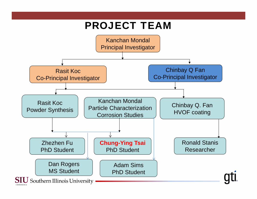
Kanchan MondalPrincipal Investigator
Rasit KocCo-Principal Investigator
Rasit KocPowder Synthesis
Kanchan MondalParticle Characterization
Corrosion Studies
Zhezhen FuPhD Student
Chinbay Q FanCo-Principal Investigator
Chinbay Q. FanHVOF coating
Chung-Ying TsaiPhD Student
Ronald StanisResearcher
PROJECT TEAM
Dan RogersMS Student
Adam SimsPhD Student
HVOF, Flame Spray Coatings
GTI project number 21397Chinbay Fan and Ronald Stanis
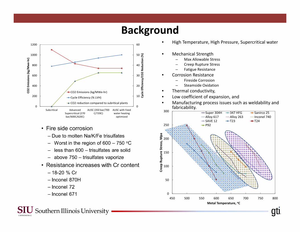
Background
0
10
20
30
40
50
60
0
200
400
600
800
1000
1200
Subcritical AdvancedSupercritical (270bar/600C/620C)
AUSC (350 bar/700C/720C)
AUSC with Feedwater heatingoptimized
Cycle Efficiency/CO
2 Re
duction (%
)
CO2 Em
issio
ns (kg/Mwe‐hr)
CO2 Emissions (kg/MWe‐hr)
Cycle Efficiency (% LVH)
CO2 reduction compared to subritical plants
0
50
100
150
200
250
300
450 500 550 600 650 700 750 800
Creep Ru
pture Stress, M
pa
Metal Temperature, oC
Super 304H 347 HFG Sanirco 25Alloy 617 Alloy 263 Inconel 740SAVE 12 T23 T24P92
• High Temperature, High Pressure, Supercritical water
• Mechanical Strength– Max Allowable Stress– Creep Rupture Stress– Fatigue Resistance
• Corrosion Resistance– Fireside Corrosion– Steamside Oxidation
• Thermal conductivity, • Low coefficient of expansion, and • Manufacturing process issues such as weldability and
fabricability.
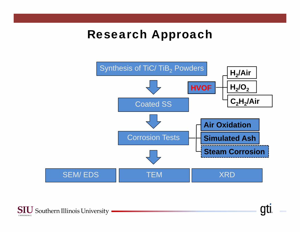
H2/Air
H2/O2
C2H2/Air
Simulated Ash
Synthesis of TiC/ TiB2 PowdersSynthesis of TiC/ TiB2 Powders
Coated SSCoated SS
SEM/ EDSSEM/ EDS
Corrosion TestsCorrosion Tests
HVOF
TEMTEM XRDXRD
Air Oxidation
Steam Corrosion
Research Approach
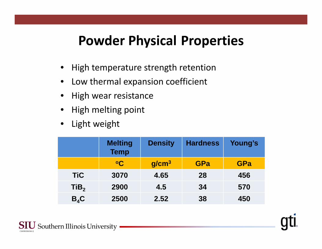
Powder Physical Properties
• High temperature strength retention• Low thermal expansion coefficient• High wear resistance• High melting point• Light weight
Melting Temp
Density Hardness Young’s
oC g/cm3 GPa GPaTiC 3070 4.65 28 456TiB2 2900 4.5 34 570B4C 2500 2.52 38 450
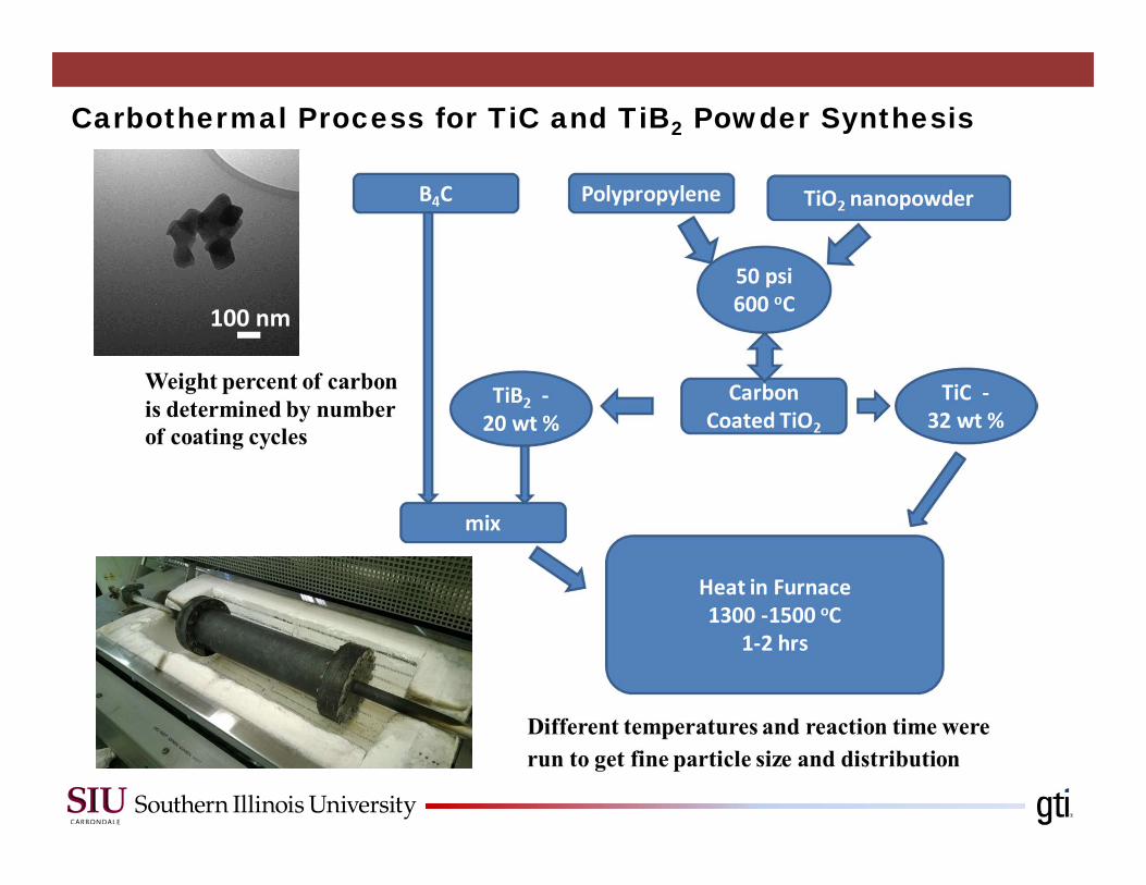
Carbothermal Process for TiC and TiB2 Powder Synthesis
100 nm
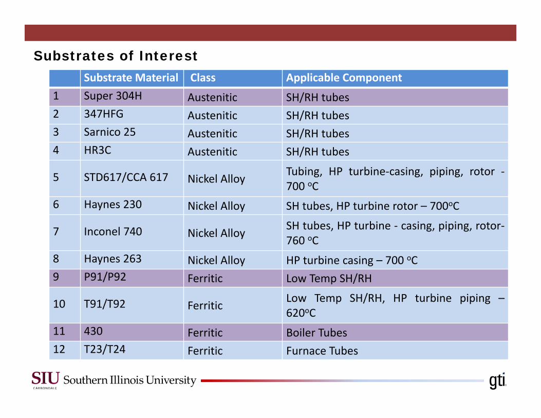
Substrate Material Class Applicable Component1 Super 304H Austenitic SH/RH tubes2 347HFG Austenitic SH/RH tubes3 Sarnico 25 Austenitic SH/RH tubes4 HR3C Austenitic SH/RH tubes
5 STD617/CCA 617 Nickel Alloy Tubing, HP turbine‐casing, piping, rotor ‐700 oC
6 Haynes 230 Nickel Alloy SH tubes, HP turbine rotor – 700oC
7 Inconel 740 Nickel Alloy SH tubes, HP turbine ‐ casing, piping, rotor‐760 oC
8 Haynes 263 Nickel Alloy HP turbine casing – 700 oC9 P91/P92 Ferritic Low Temp SH/RH
10 T91/T92 Ferritic Low Temp SH/RH, HP turbine piping –620oC
11 430 Ferritic Boiler Tubes12 T23/T24 Ferritic Furnace Tubes
Substrates of Interest
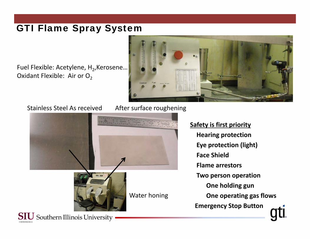
Fuel Flexible: Acetylene, H2,Kerosene…Oxidant Flexible: Air or O2
GTI Flame Spray System
Stainless Steel As received After surface roughening
Water honing
Safety is first priorityHearing protectionEye protection (light)Face ShieldFlame arrestorsTwo person operation
One holding gunOne operating gas flows
Emergency Stop Button
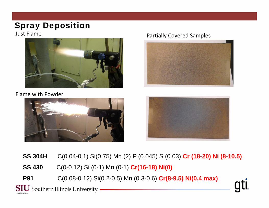
Just Flame
Flame with Powder
Partially Covered SamplesSpray Deposition
SS 304H C(0.04-0.1) Si(0.75) Mn (2) P (0.045) S (0.03) Cr (18-20) Ni (8-10.5)
SS 430 C(0-0.12) Si (0-1) Mn (0-1) Cr(16-18) Ni(0)
P91 C(0.08-0.12) Si(0.2-0.5) Mn (0.3-0.6) Cr(8-9.5) Ni(0.4 max)
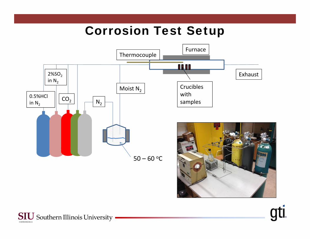
N2CO2
2%SO2in N2
0.5%HClin N2
Moist N2
50 – 60 oC
Exhaust
Thermocouple
Crucibles with samples
Furnace
Corrosion Test Setup
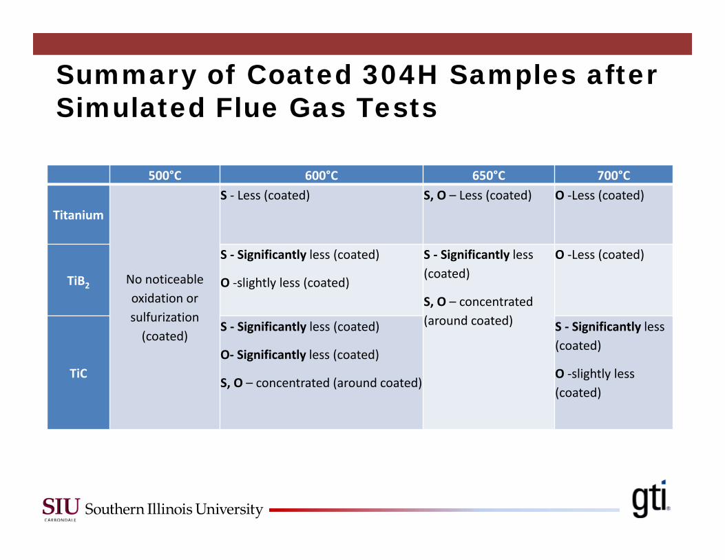
500°C 600°C 650°C 700°C
Titanium
No noticeable oxidation or sulfurization (coated)
S ‐ Less (coated) S, O – Less (coated) O ‐Less (coated)
TiB2
S ‐ Significantly less (coated)
O ‐slightly less (coated)
S ‐ Significantly less (coated)
S, O – concentrated (around coated)
O ‐Less (coated)
TiC
S ‐ Significantly less (coated)
O‐ Significantly less (coated)
S, O – concentrated (around coated)
S ‐ Significantly less (coated)
O ‐slightly less (coated)
Summary of Coated 304H Samples after Simulated Flue Gas Tests
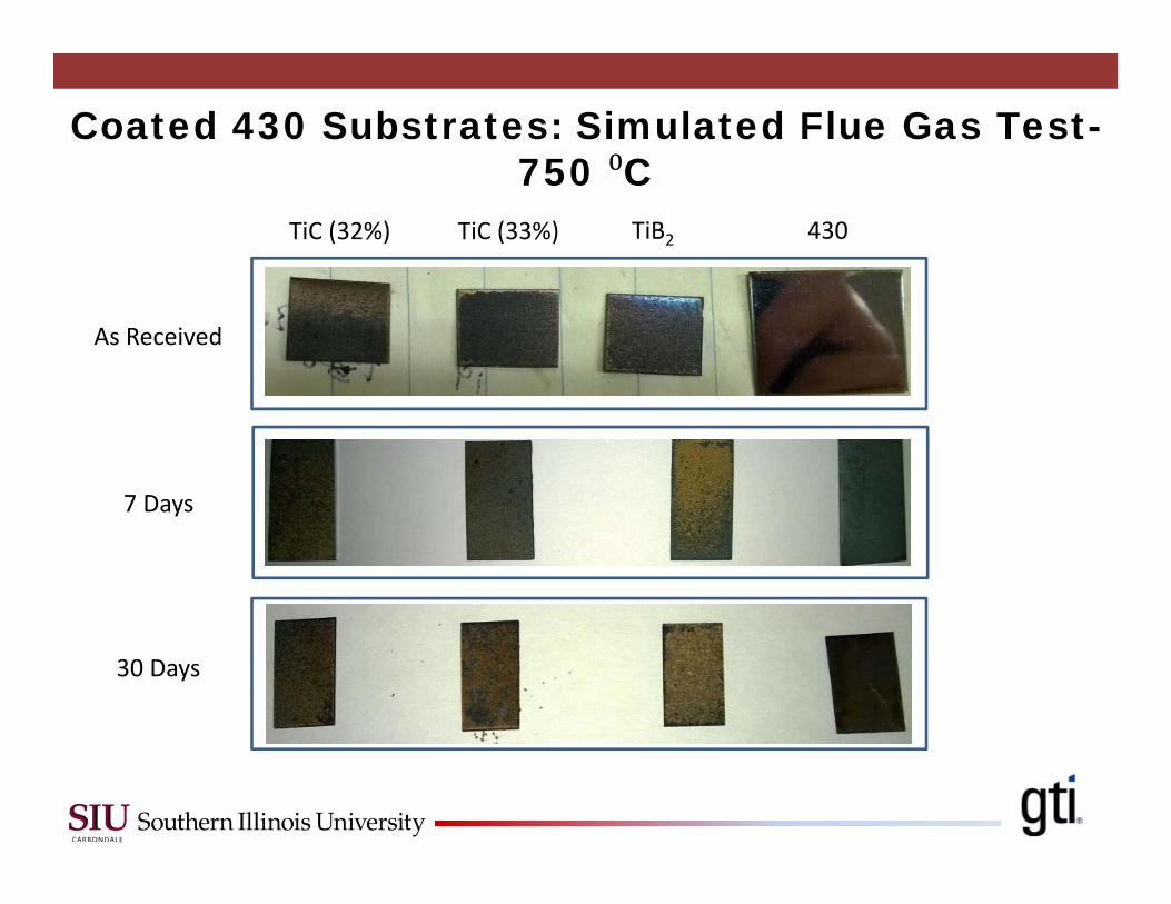
Coated 430 Substrates: Simulated Flue Gas Test-750 C
TiC (32%)
7 Days
30 Days
As Received
TiC (33%) TiB2 430
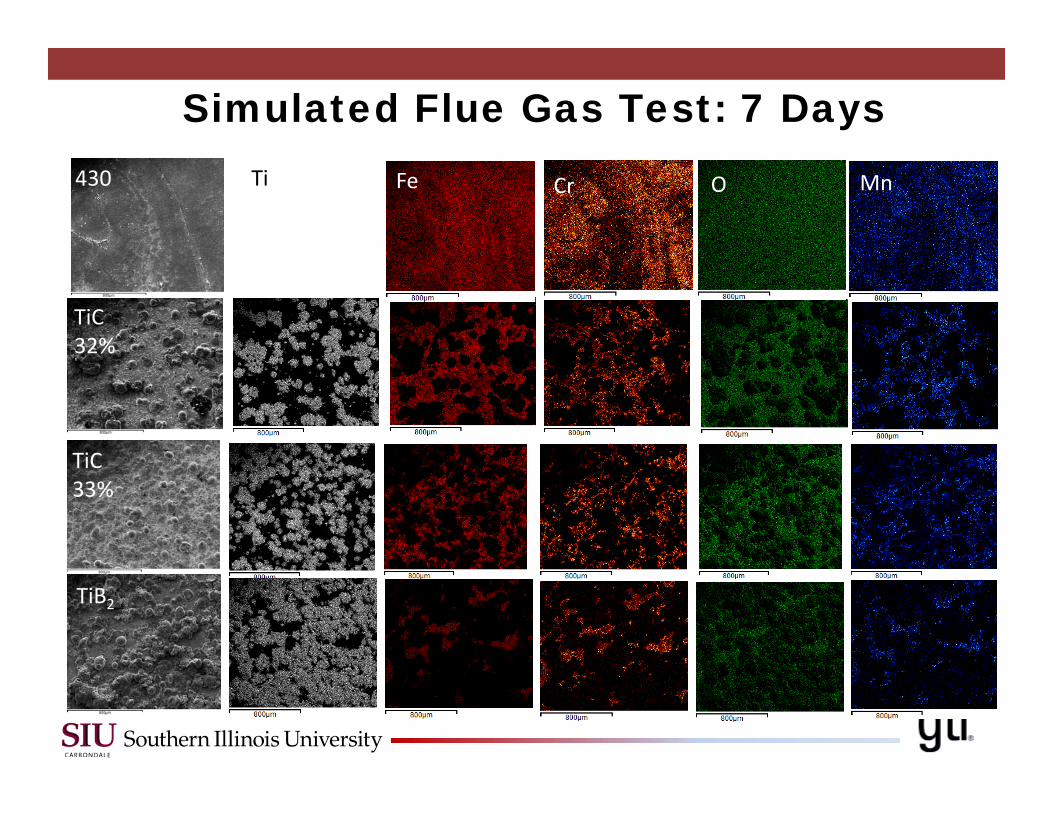
Simulated Flue Gas Test: 7 Days
TiB2
TiC33%
TiC32%
430 FeTi OCr Mn
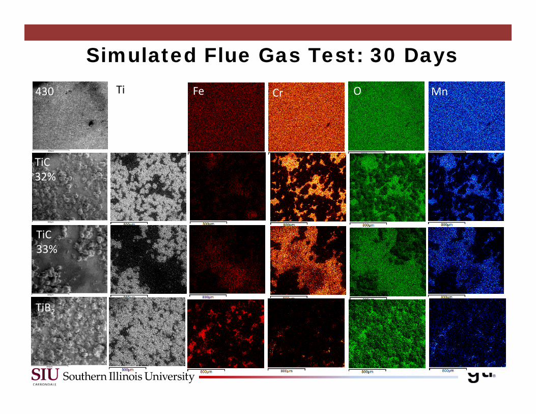
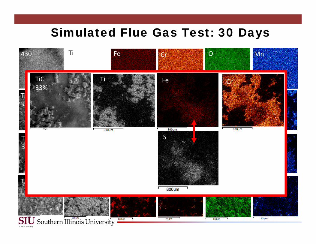
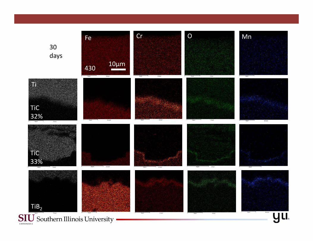
Simulated Flue Gas Test: 30 Days
TiB2
TiC33%
TiC32%
430 FeTi OCr Mn
Simulated Flue Gas Test: 30 Days
TiB2
TiC33%
TiC32%
430 FeTi OCr Mn
FeTi CrTiC33%
S
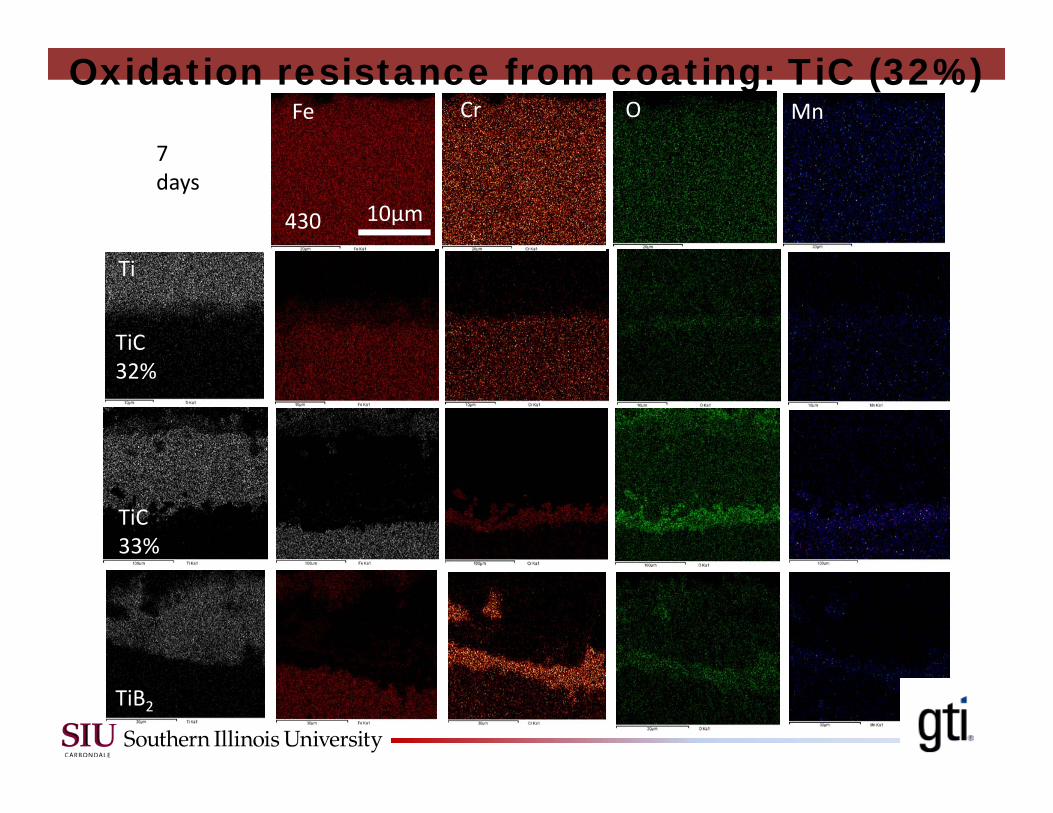
7 days
Fe
Ti
OCr Mn
TiB2
TiC33%
TiC32%
430 10μm
Oxidation resistance from coating: TiC (32%)
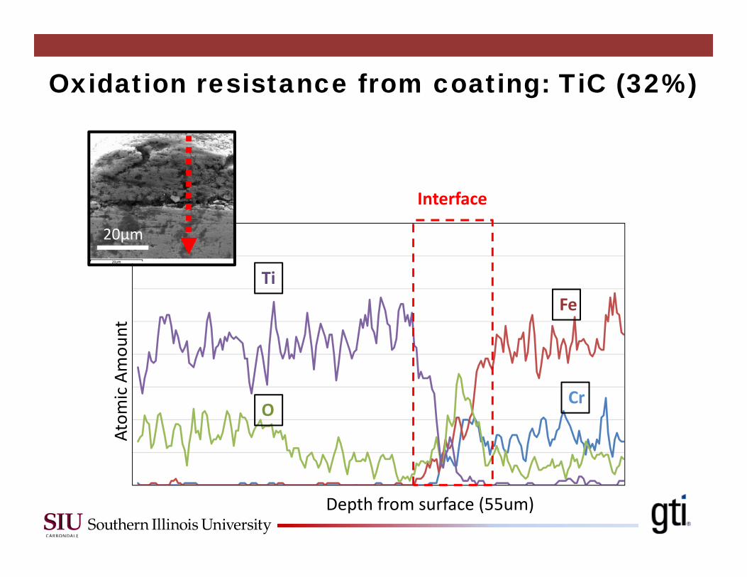
Oxidation resistance from coating: TiC (32%) Atom
ic Amou
nt
Depth from surface (55um)
Interface
Ti
O
Fe
Cr
20μm
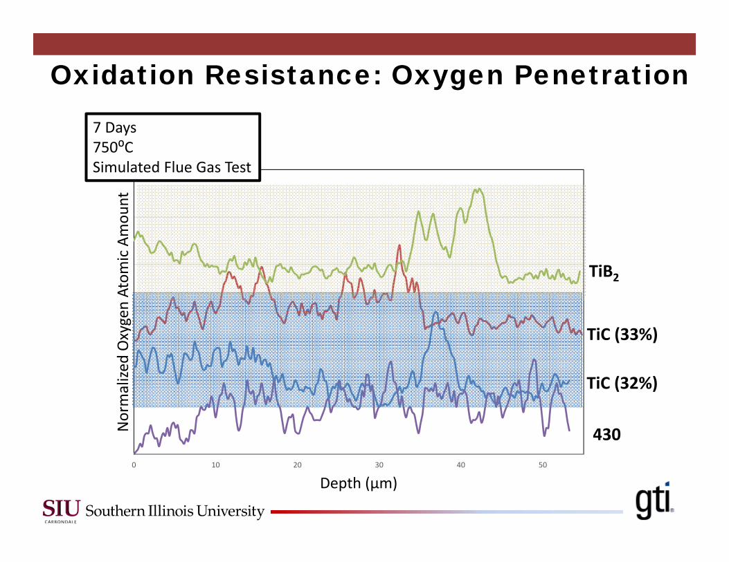
Oxidation Resistance: Oxygen Penetration
0 10 20 30 40 50
Normalize
d Oxygen Atom
ic Amou
nt
Depth (μm)
430
TiC (32%)
TiC (33%)
TiB2
7 Days750⁰CSimulated Flue Gas Test
30 days
Fe
Ti
OCr Mn
TiB2
TiC33%
TiC32%
430 10μm
0 5 10 15 20 25 30 35 40 45 50
Normalize
d Oxygen Atom
ic Amou
nt
Depth (μm)
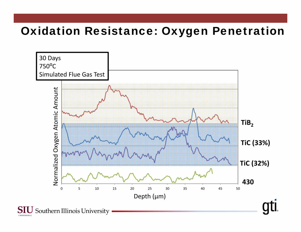
Oxidation Resistance: Oxygen Penetration
30 Days750⁰CSimulated Flue Gas Test
430
TiC (32%)
TiC (33%)
TiB2
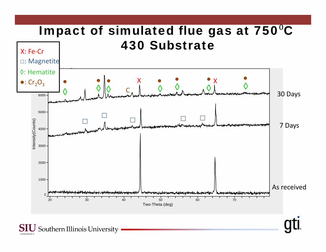
Impact of simulated flue gas at 750 C430 Substrate
20 30 40 50 60 70Two-Theta (deg)
0
1000
2000
3000
4000
5000
6000
7000
Inte
nsity
(Cou
nts)
[ ] _
X XC◊ ◊ ◊ ◊ ◊ ◊ ◊
□ □ □ □ □
● ● ● ● ● ● ●
X: Fe‐Cr□: Magnetite◊: Hematite●: Cr2O3
As received
7 Days
30 Days
20 30 40 50 60 70Two-Theta (deg)
0
500
1000
1500
2000
2500
3000
3500
Inte
nsity
(Cou
nts)
[ ] _
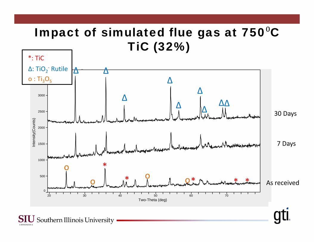
*: TiCΔ: TiO2
‐ Rutileo : Ti3O5
oo o o
** *
Δ Δ
Δ
Δ
Δ ΔΔΔ
Δ
* *
Impact of simulated flue gas at 750 CTiC (32%)
As received
7 Days
30 Days
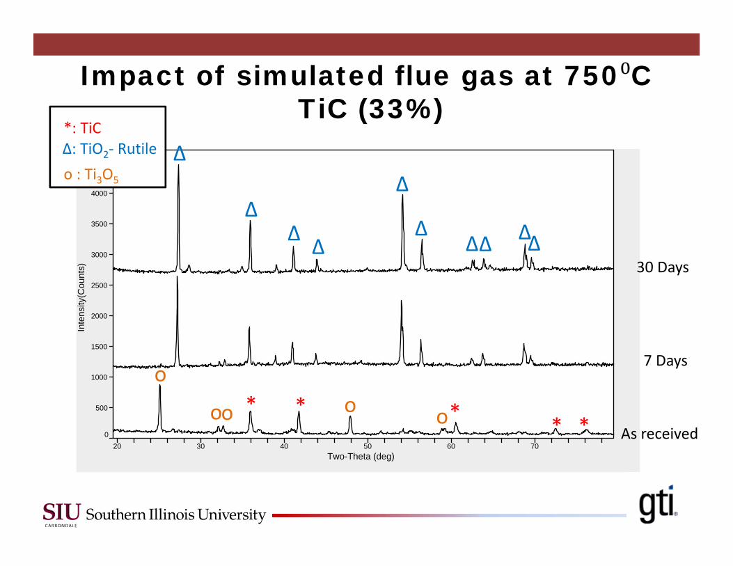
20 30 40 50 60 70Two-Theta (deg)
0
500
1000
1500
2000
2500
3000
3500
4000
4500
Inte
nsity
(Cou
nts)
[ ] _
*: TiCΔ: TiO2‐ Rutileo : Ti3O5
o*
Δ
oo o* * * *
Δ
Δ
Δ
Δ
Δ ΔΔΔΔ
oAs received
7 Days
30 Days
Impact of simulated flue gas at 750 CTiC (33%)
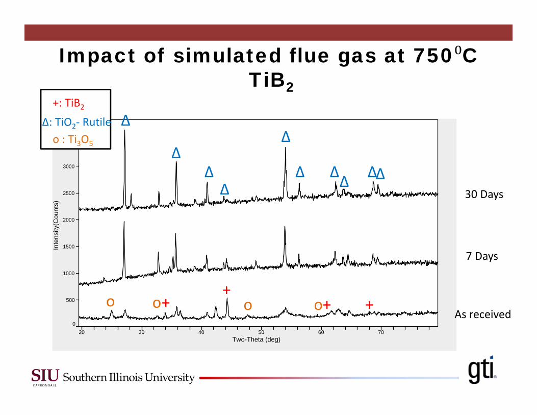
Impact of simulated flue gas at 750 CTiB2
20 30 40 50 60 70Two-Theta (deg)
0
500
1000
1500
2000
2500
3000
3500
Inte
nsity
(Cou
nts)
[ ] _
As received
7 Days
30 Days
o
Δ
+o o o+
+ +
Δ
Δ
Δ
ΔΔ ΔΔ ΔΔ
+: TiB2Δ: TiO2‐ Rutileo : Ti3O5
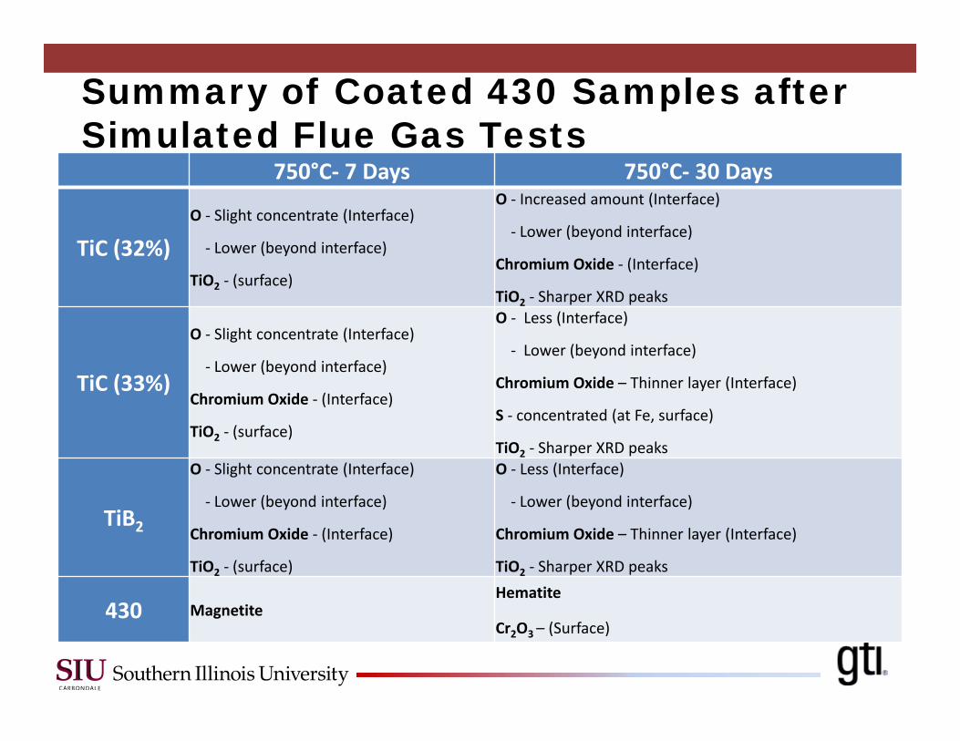
750°C‐ 7 Days 750°C‐ 30 Days
TiC (32%)O ‐ Slight concentrate (Interface)
‐ Lower (beyond interface)
TiO2 ‐ (surface)
O ‐ Increased amount (Interface)
‐ Lower (beyond interface)
Chromium Oxide ‐ (Interface)
TiO2 ‐ Sharper XRD peaks
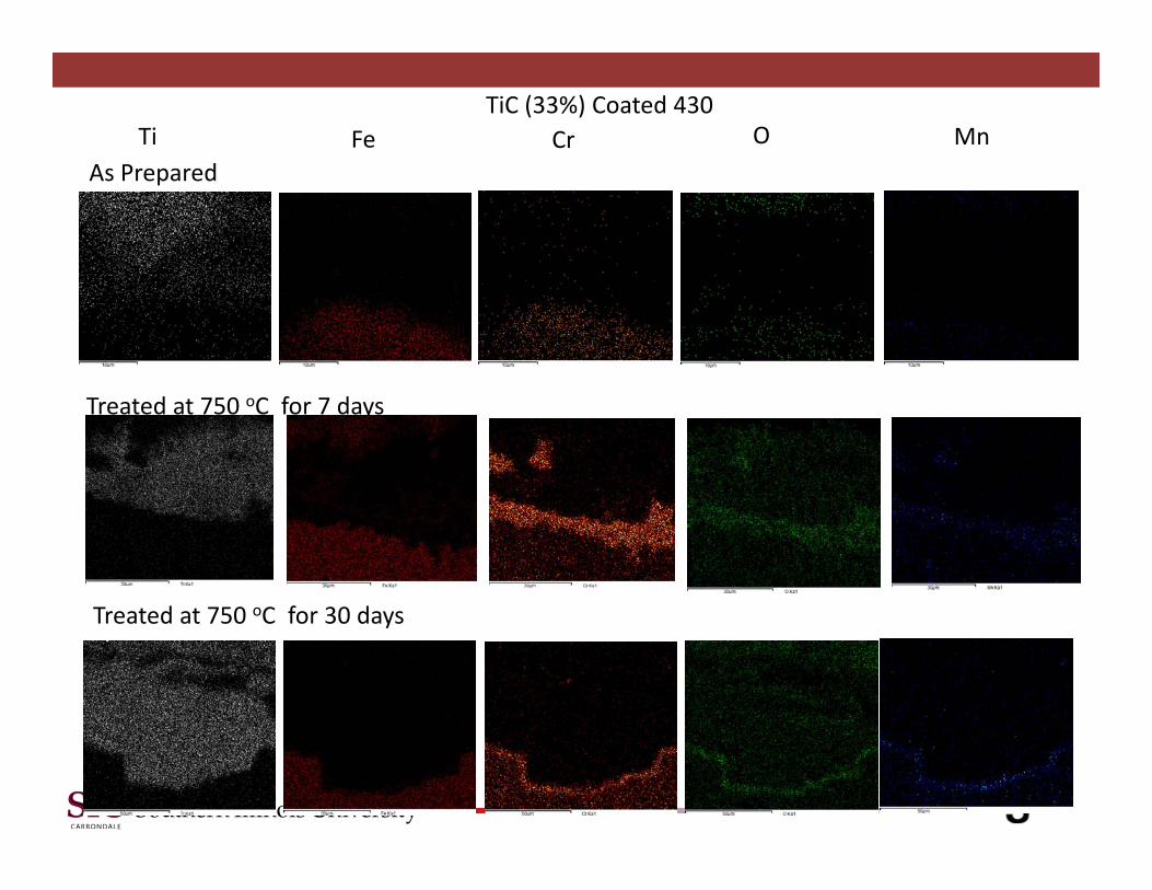
TiC (33%)
O ‐ Slight concentrate (Interface)
‐ Lower (beyond interface)
Chromium Oxide ‐ (Interface)
TiO2 ‐ (surface)
O ‐ Less (Interface)
‐ Lower (beyond interface)
Chromium Oxide – Thinner layer (Interface)
S ‐ concentrated (at Fe, surface)
TiO2 ‐ Sharper XRD peaks
TiB2
O ‐ Slight concentrate (Interface)
‐ Lower (beyond interface)
Chromium Oxide ‐ (Interface)
TiO2 ‐ (surface)
O ‐ Less (Interface)
‐ Lower (beyond interface)
Chromium Oxide – Thinner layer (Interface)
TiO2 ‐ Sharper XRD peaks
430 MagnetiteHematite
Cr2O3 – (Surface)
Summary of Coated 430 Samples after Simulated Flue Gas Tests
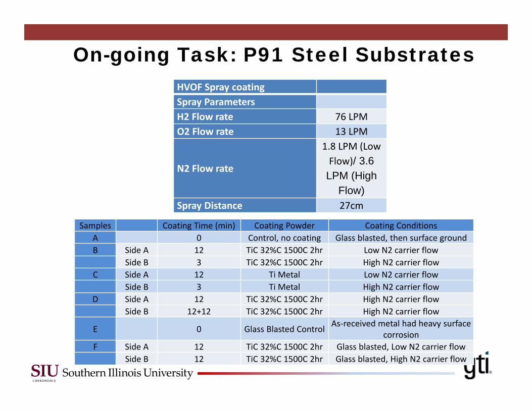
Samples Coating Time (min) Coating Powder Coating ConditionsA 0 Control, no coating Glass blasted, then surface groundB Side A 12 TiC 32%C 1500C 2hr Low N2 carrier flow
Side B 3 TiC 32%C 1500C 2hr High N2 carrier flowC Side A 12 Ti Metal Low N2 carrier flow
Side B 3 Ti Metal High N2 carrier flowD Side A 12 TiC 32%C 1500C 2hr High N2 carrier flow
Side B 12+12 TiC 32%C 1500C 2hr High N2 carrier flow
E 0 Glass Blasted Control As‐received metal had heavy surface corrosion
F Side A 12 TiC 32%C 1500C 2hr Glass blasted, Low N2 carrier flowSide B 12 TiC 32%C 1500C 2hr Glass blasted, High N2 carrier flow
HVOF Spray coatingSpray ParametersH2 Flow rate 76 LPMO2 Flow rate 13 LPM
N2 Flow rate
1.8 LPM (Low Flow)/ 3.6 LPM (High
Flow)Spray Distance 27cm
On-going Task: P91 Steel Substrates
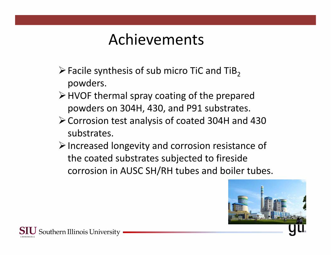
Achievements
Facile synthesis of sub micro TiC and TiB2powders.
HVOF thermal spray coating of the prepared powders on 304H, 430, and P91 substrates.
Corrosion test analysis of coated 304H and 430 substrates.
Increased longevity and corrosion resistance of the coated substrates subjected to fireside corrosion in AUSC SH/RH tubes and boiler tubes.
Acknowledgement
Thank You.
US DOE Project Number: DE-FE0008864Project Officer: Richard Dunst
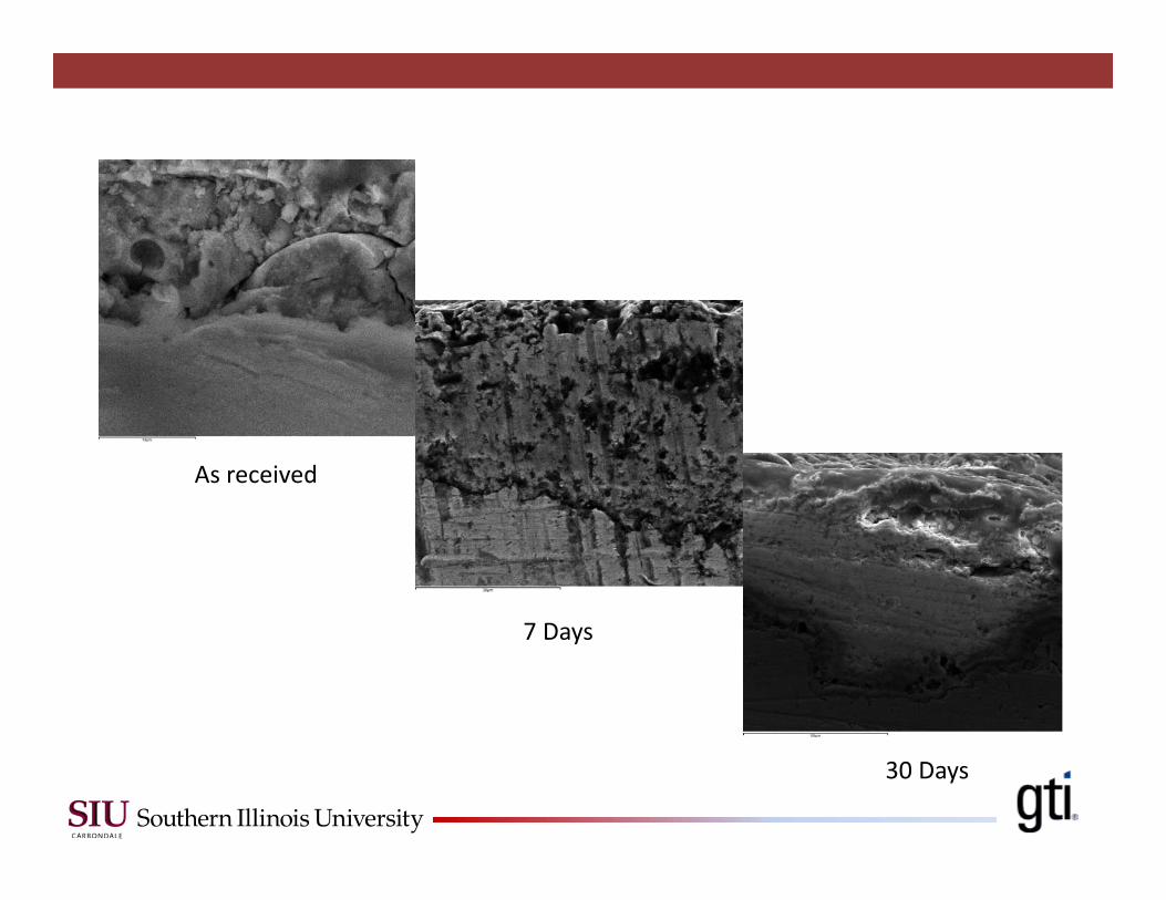
As received
7 Days
30 Days
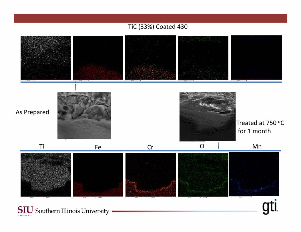
TiC (33%) Coated 430
Treated at 750 oCfor 1 month
FeTi OCr Mn
As Prepared
TiC (33%) Coated 430
Treated at 750 oC for 30 days
FeTi OCr MnAs Prepared
Treated at 750 oC for 7 days
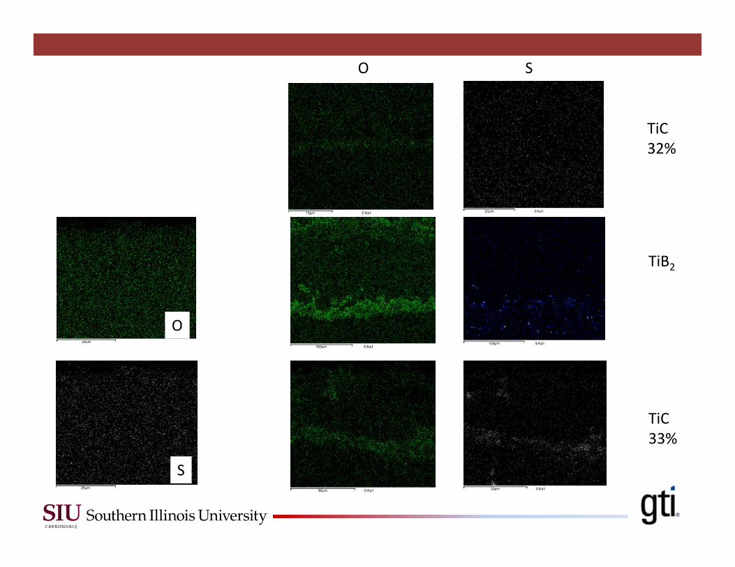
TiB2
TiC33%
TiC32%
O S
O
S
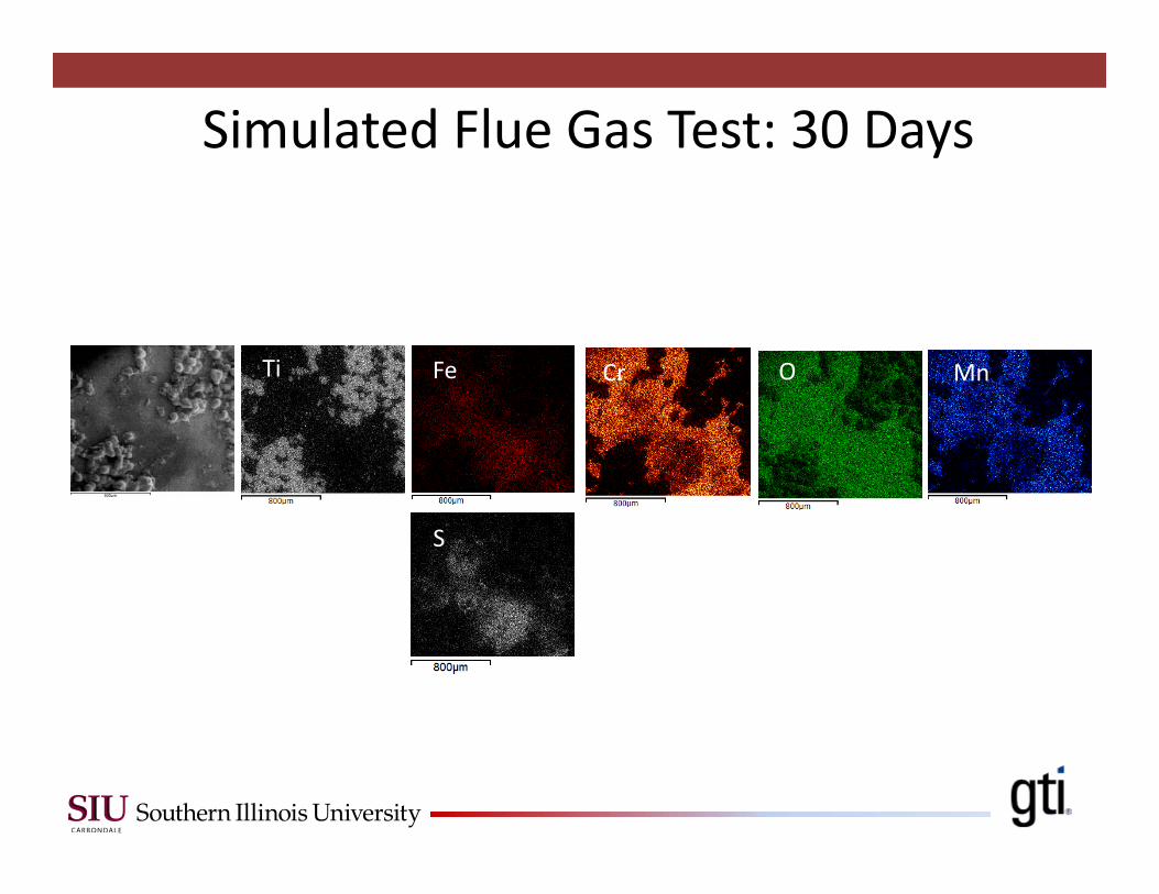
FeTi OCr Mn
S
Simulated Flue Gas Test: 30 Days
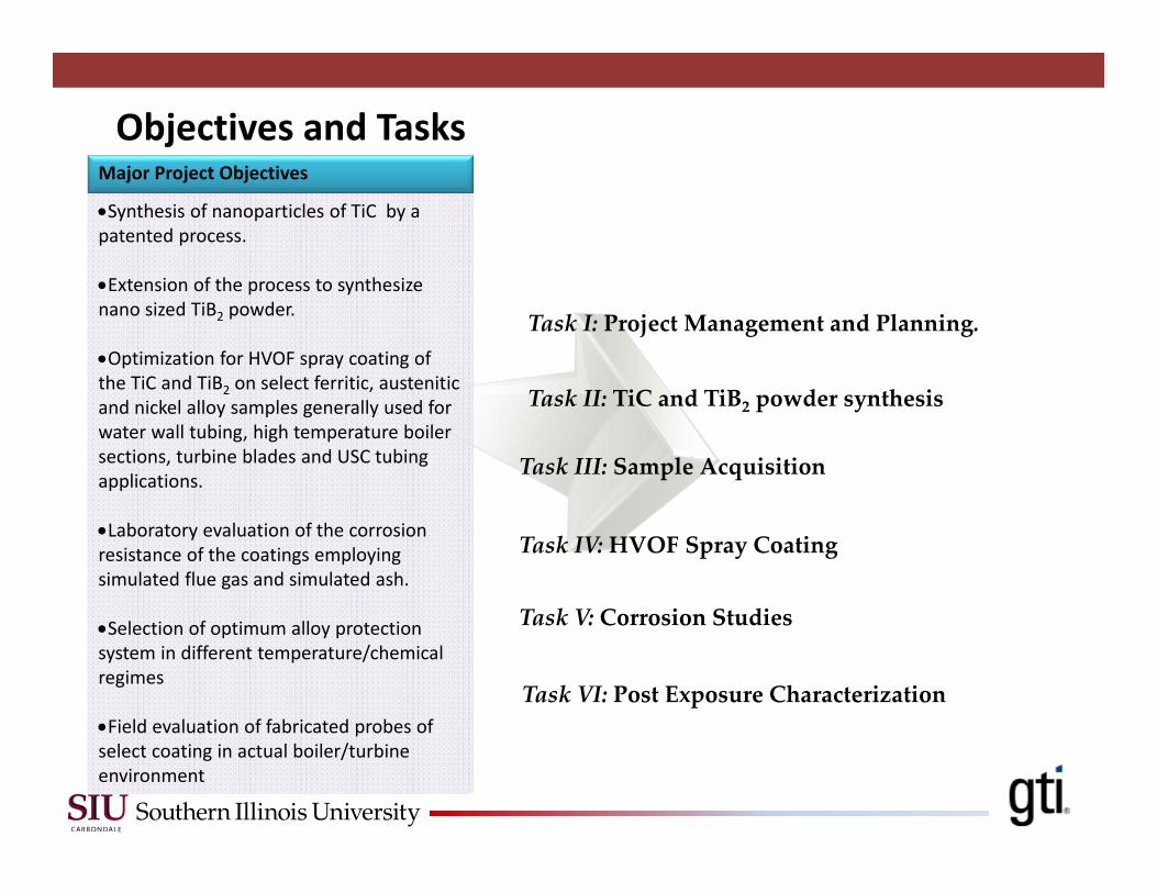
Task I: Project Management and Planning.
Synthesis of nanoparticles of TiC by a patented process.
Extension of the process to synthesize nano sized TiB2 powder.
Optimization for HVOF spray coating of the TiC and TiB2 on select ferritic, austenitic and nickel alloy samples generally used for water wall tubing, high temperature boiler sections, turbine blades and USC tubing applications.
Laboratory evaluation of the corrosion resistance of the coatings employing simulated flue gas and simulated ash.
Selection of optimum alloy protection system in different temperature/chemical regimes
Field evaluation of fabricated probes of select coating in actual boiler/turbine environment
Major Project Objectives
Objectives and Tasks
Task II: TiC and TiB2 powder synthesis
Task III: Sample Acquisition
Task IV:HVOF Spray Coating
Task V: Corrosion Studies
Task VI: Post Exposure Characterization