Embed Size (px)
Citation preview

• . ., • •
October 28, 1996 9-2~/) 9--2~'1
MEMORANDUM TO: THE FILES
FROM: Jack Guttmann, Sr. Reliability & Risk Assessment Engineer/.S/ Probabilisitc Rtsk Analysis Branch
SUBJECT:
Date:
Location:
Division of Systems Technology, RES
Syed Ali, Structural Engineer Civil Engineering and Geosciences Branch l.51 Division of Engineering, NRR
MEETING SUMMARY - SURRY PLANT WALKDOWN
June 25 and 26, 1996
Surry Nuclear Power Plant
On June 25 and 26, 1996, Virginia Power performed a walkdown of its Surry Unit 1 Nuclear Power Plant. This walkdown is part of the NEI/ASME/WOG methods development for risk-informed inservice inspection programs (RI-ISI). The purpose of the walkdown was to identify potential indirect effects/consequences from postulated pipe failures, and to identify indirect effects that would differentiate piping into different segments used in the analysis. ·
Syed Ali (NRR), Jack Guttmann (RES) and Donnie Whitehead (SNL contractor) observed the licensee's implementation of the walkdown.
In preparation for the walkdown, the licensee reviewed its:
a. IPE internll flooding analyses b. Pipe whip/jet impingement evaluations on record, Environmental and
dynamic effects design basis (FSAR) c. Appendix R safe shutdown analyses d. General arrangement and piping drawings
The licensee reviewed documents relatedito its existing Section XI ISI programs. The licensee identified systems/trains that could be affected break, it identified plant areas for plant walkdown, and it devel-0ped standardized walkdown sheets to ensure evaluation consistency (see Attachments).
The licensee stated that it performed a detailed evaluation of the consequences of floods originating in and capable of propagating from the turbine building and safeguards areas. The source of flooding identified
~\1\)~
by a

• 2
those areas were the component water system, the service water system, and the emergency safety injection water system. In addition, the licensee stated that it performed a detailed analysis of the consequences of floods originating from the RWST and fire protection system in the auxiliary building.
The areas identified for plant walkdown were:
main steam valve house charging pump cubicles service building turbine building auxiliary building near the elevator and the boric acid storage tanks
The licensee screened out the following areas from inspection based on the lack of a credible flood source in the area or low potential contribution to core damage frequency:
Diesel Generator Room Control Room Emergency Switchgear Room Cable Spreading Room Battery Room Normal Switchgear Room
Flooding that originated in containment were screened out based on the following considerations:
Consequences of failure of piping elements in most fluid systems in the containment building are bounded by that analyzed in the internal events analysis. All PRA-credited, flood susceptible, equipment in the area are qualified for a LOCA environment.
The licensee stated that it was going to verify its conclusions using its computerized imaging system. During the time of the walkdown, Unit 1 was in
· operation and the containment was inaccessible for walkdown purposes.
The licensee defined high energy lines as those operating above 200 degrees F and whose pressure exceeded 275 psig. The systems satisfying the above criteria were:
main steam line main and auxiliary feedwater lines high pressure heater drains and vents moisture separator drains auxiliary steam condensate low pressure heater drains and vents boron recovery

'. ' .• .... •
liquid waste chemical volume control system safety injection steam generator blowdown system extraction steam sample
3
Of the above listed high energy lines, the following are included in the current Section XI ISI program:
main steam lines main/auxiliary feedwater lines condensate chemical volume control system safety injection steam generator blowdown.
When performing the walkdown, the following criteria were used to assess the location of possible pipe breaks:
circumferential breaks in pipes greater than 111 at terminal ends, fitting welds, branch connections
longitudinal breaks in piping systems 411 and larger at welded attachments such as lugs and stanchions
Pipe whip initial hinge distance is calculated by an energy balance technique based on:
thrust force pipe plastic moment pipe concentrated mass at rupture point pipe mass per unit length
Jet impingement loads are a function of: system stagnation pressure jet thrust coefficient break opening area fraction of jet intercepted by target target shape factor jet impingement angle factor
Following the walkdown, the licensee executed post-walkdown technical discussions. It appeared that in most areas the postulated pipe rupture would disable the equipment within the confined quarters. The licensee was going to perform additional pipe whip analyses to assess the potential for secondary failures and the effects of certain check valve alignments (in the charging pump cubicals) to assess the possibility of draining the RWST. The auxiliary
.steam and steam drain lines are not within the scope of Section XI. However, the potential for affecting the component cooling water pumps (potential of pipe whip severing power lines to the pumps) required additional analyses. In parallel, the licensee's PRA group would perform an analysis to assess the

• e 4
risk significance of losing the CCW pumps.
The results of the analyses will be documented in the licensee's submittal.
The next milestone for the RI-ISi program is scheduled for July 31, 1996 at Richmond. At that meeting, input to the SRRA failure analysis code will undergo internal review. The NRC intends to observe that meeting.
On August 6 and 7, the NRC, the ASME, and the licensee will me~t at Portland Oregon to discuss the equations used by the SRRA computer code and compare NRC/SNL independent evaluations of the reactor coolant system with the analyses performed by the licensee.
Attachment: Meeting Handouts
DISTRIBUTION: .PDR LL- -6 PRAB Subject File Central Files (T-5 C3) WHodges BSheron MCunningham GBagchi MMayfield DJeng SDinsmore DJackson GMillman DWhitehead (SNL) FSimonen (PNL)
Document name: G:\8-7-96.MTG
To receive a copy of this document, indicate in the box: "C" = Copy without attachment/encl ure OFFICE PRAB E CEGB J
NAME JGuttmann/mb SAli DATE 10 I .:2.... /96 / /96 l" /-v/J /96
OFFICIAL RECORD COPY
lfJ00! 7 [~-----~-

MEETING SUMMARY - SURRY PLANT WALKDOWN
REC'D W/MEMO DTD 10/29/96 .... 9611130397
- NOTICE -THE ATTACHED FILES ARE OFFICIAL
RECORDS OF THE INFORMATION &
RECORDS MANAGEMENT BRANCH.
THEY HAVE BEEN CHARGED TO YOU
FOR A LIMITED TIME PERIOD AND
MUSTBERETURNEDTOTHE
RECORDS & ARCHIVES SERVICES
SECTION, T5 C3. PLEASE DO NOT
SEND DOCUMENTS CHARGED OUT
THROUGH THE MAIL. REMOVAL OF
ANY PAGE(S) FROM DOCUMENT
FOR REPRODUCTION MUST BE
REFERRED TO FILE PERSONNEL.
- NOTICE -
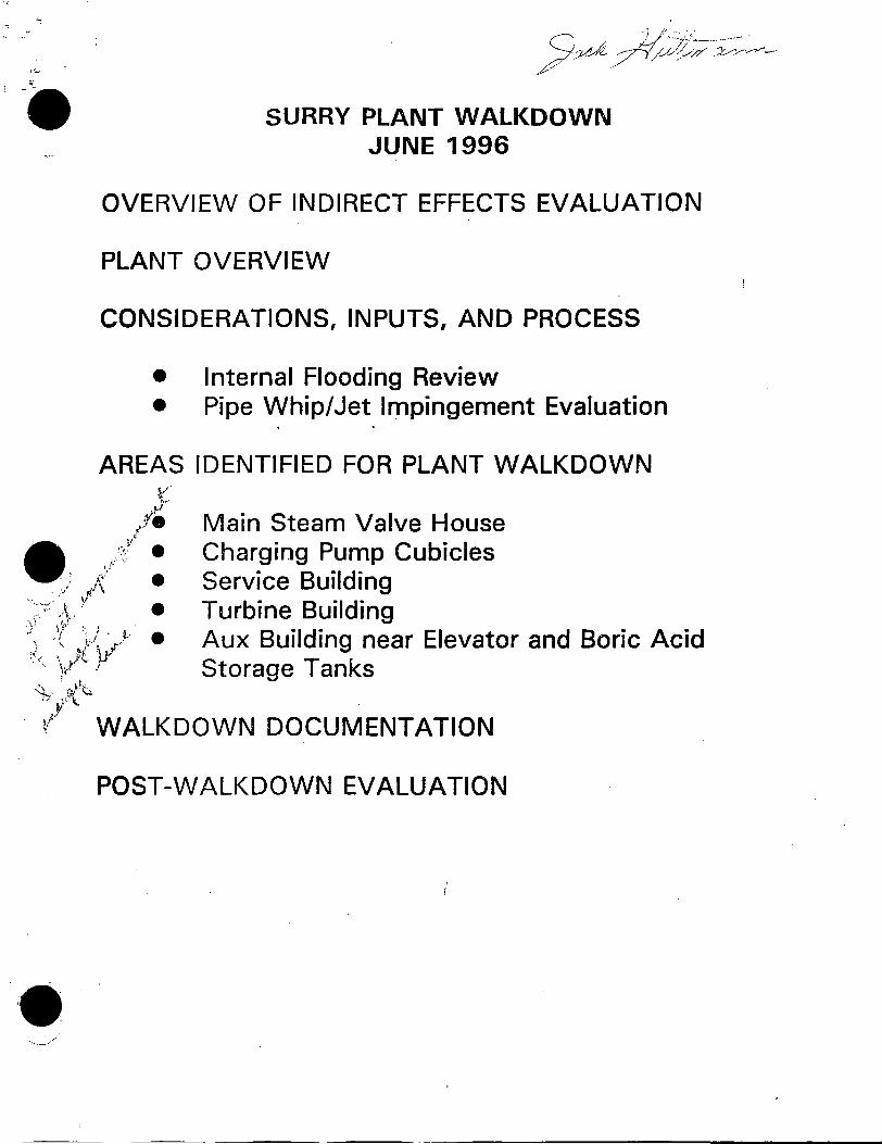
SURRY PLANT WALKDOWN JUNE 1996
OVERVIEW OF INDIRECT EFFECTS EVALUATION
PLANT OVERVIEW
CONSIDERATIONS, INPUTS, AND PROCESS
• Internal Flooding Review • Pipe Whip/Jet Impingement Evaluation
AREAS IDENTIFIED FOR PLANT WALKDOWN t
,1,.I
1J1e Main Steam Valve House
t:.Y • Charging Pump Cubicles \f~ ·~-
. ) ti"\ • Service Building
:if ",i( · ~ · : l~~i~~il~~~di~2ar Elevator and Boric Acid :;\ ',1,/c ,V Storage Tanks
\ . I)[\~ "-/:;,· fl'\. ' .
. ~l- WALKDOWN DOCUMENTATION
POST-WALKDOWN EVALUATION
• · .. __ ..

- . ~--
OVERVIEW OF INDIRECT EFFECTS EVALUATION
Purpose of Walkdown
• To review any issues in identifyihg potential indirect effects/consequences from piping failures
• Identify indirect effects that would differentiate piping segments from each other . .

ConsidLAns
• Flooding, spraying, dripping -
• Pipe Whip, jet impingement -
(. should be primarily addressed by the IPE internal flooding analyses for all plant areas
concern is prima~ily for high-energy fluid system piping

Inputs
Wi a.l ... wn
• Analyses to meet GDC- 4 "Environmental and dynamic effects design basis" (usually summarized in the FSAR)
• IPE Internal Flooding Analyses
• Appendix R -Safe Shutdown submittal
• General arrangement and piping drawings

Process-.•
~walkdown
:: ..• '
• •
I • Review existing documents which examine the local effects of pipe breaks for the systems in the ISi program
I • Identify other systems/trains affected by a break in each area
• Identify plant areas for plant walkdown
• Document evaluation. ·---
• Develop walkdown sheets for key areas.
Walkdown
• · Perform walkdown and document results, actions, issues.
Post Walkdown
• Evaluate results
• Resolve actions
'·-
'

• :- '
' ·)( . . ,f""t\ :1 .. i.l
" "r \ '; rJ 'j· . i ,. >
.. jF Q:r>e
·····.' IF ANALYSIS SUMMARY
• The following areas were screened out based on either lack of credible flood source in the area or low potential contribution to CDF:
• -Diesel Generator Room
• Control Room
• Emergency Switchgear Room
• Cable Spreading Room
• Battery Room
• Normal Switchgear Room

,. I . '· ..
•• J ' . . '
IF ANALYSIS SUMMARY (CONT'D) --
• Floods originating in Contai1:1ment were screened out based on the following:
- Consequences of failure of piping . elements in most fluid systems in the Containment are bounded by · that analyzed in the internal events an.alysis ( e.g. LOCAs) .
-All PSA-credited,. flood susceptible, equipment in the area are qualified for a LOCA environment.

•• IF ANALYSIS SUMMARY (CONT'D)
• Th·e consequences of floods origii;iating in and capable of propagating from the fallowing areas were evaluated in detail:
Area Flood Source ·-- -Turbine Building CW/SW .
. -. Safeguards Area SI
• Consequences of floods originating from R WS T and fire protection system in the Auxiliary Building were evaluated in detail.

:. (. IF ANALYSIS SUMMARY (CONT'D)
• The Consequences of floods Originating in, and being confined to, the fo~lowing areas were considered insignificant based on their low·-potential contribution to CDF:
• Turbine Building
• Safeguards Area
. . • .. .

USE OF IF IN RBISI PROGRAM • Internal Flooding RBISI
,,,....
• Low inventory I No ~irect impact
• screened out 00~ 1JJ ~,t.Y • as insignificant 4~v
I ~-.:io cw~ ,e._o--u.J:1A!..Q~
I . ---------------------------------------------------------------\ : Sufficient inventory I
I
• assume loss of all I Assume loss of all -----------·--targets
• targets. If low contribution I ".'""-·-
• screen out. I . --------------------------------------------------------------• Suffcient inventory and
• significant consequences.
• Detailed analysis required.
I Result of detailed ( I analysis \ lJ.) ,.d_Jo--..,_,._,,._
I J _ Above information based on flooding sources, potential targets, critical height, flood propagation and available pathways

Pipe W.Considerations. ;. High-energy line systems
* *
*
* * *
during normal plant conditions, are either in operation or maintained r
pressurized under conditions where either .of the following are met: maximum operating temperature exceeds 200F,
and .. maximum operating pressure .exceeds 275 psig
Surry systems main steam line main feedwater line (including auxiliary feedwater system) high pressure heater drains and vents moistu_re separator drains auxiliary steam condensate low pressure heater drain.s and vents boron recovery liquid waste chemical· volume control system safety injection SG blowdown system extraction steam
- - sample DJ.~
l* - piping systems included in,JSI progra~
•

.
• •
PIPE WHIP AND JET IMPINGEMENT
LOCATION AND TYPE OF ASSUMED PIPE RUPTURES
~ I - Circumferential breaks in piping greater than 1 " at terminal ends, fitting welds, branch connections
• •
Longitudinal breaks in piping systems 4" and larger at welded attachments such as lugs and stanchions
PIPE WHIP INITIAL HINGE DISTANCE
Calculated by an energy balance technique based on:
Thrust force Pipe plastic moment Pipe concentrated mass at rupture point Pipe mass per unit length
• JET IMPINGEMENT LOAD
Impingement loads are a function of: System stagnation pressure Jet thrust coefficient Break opening area Fraction_ of jet intercepted by target Target shape factor Impingement angle factor f 4- -1;,d::

.
• • • •
... ~----.
POST-WALKDOWN EVALUATIOf\J
Review indirect effects identified
Complete wafkdown action items
Map indirect effects to piping segments

l .• ••• INDIRECT EFFECTS W ALKDOWN WORKSHEET
Building: 17 (AB) Elevation: 13' Cubicle/Section: 17-AB (Aux. Building at 13' elevation)
POTENTIAL HAZARDS/POSTULATED EFFECTS
Potentlal H87.81'ds Postulated Effect
Floodlq/Spray Source(s)
High Temperature/Humidity Sources (High Energy Lines only)
Pipe Whip Source(s) ·(High Energy Lines only)
·--
Jet Impingement Source(s) (High Energy Lines only)
. Comments:
Conclusions/ Actions:

• ( •. ·,
\ •• Indirect Effect Walkdown Worksheet
Building: Am. Building Area/Sec.: 17-AB (General Area of 13' FJeyation) me.-.: 13•
Potential Taqets in 1be Area Potential Hazards
System Component Tag Number Train Needed F1ooc1in8'Spray High Tempi Jet Impingement Pipe Whip Type for SD? Source Humidity Source
Source Location Source Location ..
CH MOV l-CH-MOV-1115B A/B No 1. Fire protection line
CH Cable 1-CH~P-lArelated cable A Ye1 2. RWST lines
CH Cable l-CH-P-lB related cable B Ye1
CH Cable 1-CC-P-lC related cable A/B Yes See note 2
cc Cable 1-CC-P-lA related cable A Yes
cc Cable 1-CC-P-lB related cable B Yes . cc Cable 1-CC-P-lC related cable Yes
cc Cable . 1-CC-P-lD related cable Yes --
SI Pipe ·*-- RWST related piping A/B Yes
CH Pipe CVT related piping A/B No
Notes:
1. If no potential hazard 11 identified, state none.
2. Due to the existence of numerous openinga, water accumulation in this section of the AB is not possible. Hence, flood-induced damage to the equipment located in this section is not credible. However, floods originating from components located here will propagate to the 2' elevation and can potentially cause significant damage.
Comments:

l
FIGURE 2: SURRY AUXILIARY BUILDING 131-0" ZONE KEY PLAN Rev. 11
=lC-3B =tC-18B
co
AB-13G
AB-13·.B ---
AB-13F
AB-13C AB-13C
AB-13A
•. , Notes: 1) Bold designates EQ barr1er 2) The celling between AB-138 and AB-27 Is an EQ barrier 3) The floor between AB-138 and AB-28 Is an EQ barrier-
AB-13G
AB-13B
RC-38 RC-188
-'-- AB-13E AB-13D
S8-9A AB-13D AB-13E
S8-9A
COLUMN NO.
1 n i:. 11

I ' ~
\ ' -
-· •• .
: .. ·:. NON- REGEt-J &nd SEAL WATER HEAT EXCHANGER ROOM
G-14, 13' ELEV.
1. 1-Cl+E-1 17. 1-BR-91 33. NOT LABELED 2. 1..cc-848 18. 1-CH-230 34. 2-CC-437
~ . ~3. 1-CC-447 19. 1-CH-MOV-2115E 35. 2-CH-E-1 4. 1-CC-443 20. 1-CH-MOV-21150 36. 2-CC-439 5. 1-CC-438 21. 2-CH-MOV-2115C 37. 2-CC-438 6. 1-CC-439 22. 2-CH-MOV-211 SE 38.2-cc-447 7. 1-CH-E-2 23. 2-CH-230 8. 1-CC-437 24. 2-BR-91
~L~l;S ~QI Sl:tCWt:I ··,".·'
9. NOT LABELED 25. 2-CC-843 1 O. NOT LABELED 26. 2-CC-TCV-203 t-CC-442 ___ t~ ---
%1. 2-Cc-440 ::·-.
11. 1-CC-436 --·_·1~ ·.-:;,.-~~2-cc-443 .:.-:.J,.
12. 1-CC-435 28.2-CH-E-2 · .. 2-CC-848 _·_::__;_._ 2-cc-445 ..
13. 1-CC-845 29.2-CC-845 .. :~ 2-CC-RV-209 2-CC-RV-210 14. 1-CC-TCV-103 30.2-Cc-435 . · .• = .... -
15. 1-CC-440 31.2-CC-844 ··-. _____ .,.. 16. 1-CC-843 32. NOT LABELED ..
. ...
AI.ARA COMPONENT LOCATOR MAP-

: ..... "'.l <· r ' '- I ,.:.. ~ I .~ i
BORON EVAPORATOR BOTTOMS TK. ROOM 13' ELEV.
1. 1-LW-TK-7A 2. 1-LW-168 3. 1-LW-162
· 4. 1-LW-164 5. 1-LW-166 6. 1-LW-TK-78 7. 1-LW-165 8. t-LW-163 9. t-LW-169. 1 O .. t-LW-384-11. 1"-LW-385 12. 1~LW-161
13. 2-CH-281 14. 2-CC-285 15. 2-CH-280 16. 2-CH289 17~ 1-BR-TK-5 18. 1.;BR-PCV-134 19. t-BR-PCV-137 20. 1-BR-RV-115
. 2.1. 1;.BR-191 22.. 1.-BR-205 23. 1 ~eR-206
VALVES NOT SHOWN 2-CH-291
1-BR-LT-114
Ar.ARA COMPONENT LOCATOR MAP

0 -• ~ 0
fo
1. 1-BR-E-SA 2. 1-BR-318 3. 1-BR-317 4. 1-CC-459 5. 1-BR-P-3A 6. 1-BR-S-3A 7. 1-BR-164 8. 1-BR-163 9. 1-BR-165 1 O. 1-CC-460 11. t-CC-461
®
BORON EVAPORATCF. ROOM-· 13' ELEV.
12. 1-CG-455 23. 1-CC-464 13. 1-CG-456 24. 1-BR-185 14. 1-CG-458 25. 1-BR-186 15. 1-CC-4;vC-, 26. 1-BR-187 16. 1-CC-466 27. 1-BR-S-38 17. 1-BR-P-38 28. 1-BR-E-5B 18. 1-CG-463 29. 1-BR-322 19. 1-CG-467 30. 1-BR-EV-1 A 20. 1-CG-468 31. 1-BR-EV-1B 21. 1-CC462 22. 1-CG-465
ALARA C01'APONENT LOCATOR MAP
~
4..0 . . -0
. le.
o's
., ._._ ..

LIQUID WASTE E'vAP. ROOM - - -
13' ELEV.
1. 1-LW-FCV-105 15. 1-LW-318 29. 1-CC-939 2. 1-LW-452 16. 1-LW-TK-58 30. 1-LW-210 3. 1-LW-330 17. 1-LW-218 31. 1-LW-436 4. 1-LW-331 18. 1-LW-LCV-105 32. 1-LW-RV-103 5. · 1-LW-319 19 .. 1-LW-222 33. 1-CC-339 6. 1-LW-TK-SA 20. 1-LW-320 · 34. 1-LW-E-2 7. 1-LW-217 21. 1-CC-337 35. t-CC-941 8. 1-LW-221 22. t-CC-338 36. 1';..LW-PCV-111 9. 1-LW-219 23. 1"-CC-POV-607A · 37. 1"-CC-340 10. 1-LW-687 24. 1'-C~336 38. 1'-GW-55 11. 1-LW-334 25. t-CC-POV-607B 39. 1"-CC-942 12. 1-LW-220 26. 1"-CC-326. 40. 1-LW-EV-1 13. 1-LW-453 27. 1-CC-335 41. 1'-LW-TCV-100 14. 1-LW-454 28. 1"-LW-TI<-4 -·
ALARACO:MPONENTLOCATORMAP

\ ,, /
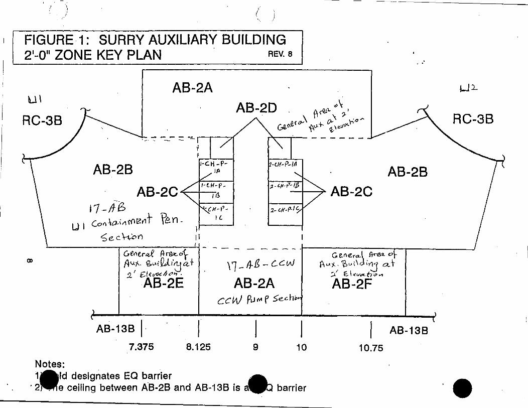
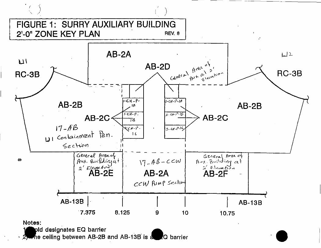
FIGURE 1: SURRY AUXILIARY BUILDING 2 1-0 11 ZONE KEY PLAN REV. 8
U\
RC-38
AB-28
AB-2A
,; ,, r---'---f
1-C.H-P-111
AB-2 C ......._,._, 11
17 .-/fG ' U I Co"·\a-il\r()~iff fen -
1 __ _.
Se. C \-,.,.o )') \ I
'l.-CH-t"-111
RC-38
AB-28
------.------··- - - -C.,et,er~e It n'e:c. o\, -' - - - -t---------,.---r-----.......J G e."era..\ A-rea. 0 \-
a,
Notes:
Av..,;... Q.~l,QJ.,·~u+ 2.. 1 £, I e vr;,t: .6 ,~11 ·
AB-2E
AB-138 I· 7.375 8.125
\1-~&-ccw
AB-2A CCW Pi.J"" p .$"echo
I 9 10
1 d designates EQ barder A ·2) e ceiling between AB-28 and AB-138 is aa:, barrier
P, ,..cf: ~, .. i\cli~ oJ· ;i_' f, \ Jl.V~ h .:J .-,
AB-2F
AB-138
10.75
••

.. · .. ·.:.·
· .. ··.
.·· .........
---,:....:..,· -
.:-·:, . .,..,-··-~·
1. 1-SW-186 2. 1-SW-185 3. 1-CH-P-1 B 4. 1-SW-TCV-1088 5. 1-SW-126 6 .. 1-SW-125 7. 1-CH-499 8. 1-SW-183 9. 1-SW-184 10. 1-CH-P-1108
1-B CHARGIN~ PUMP CUBE 13' ELEV.
11. 1-CH-1269A 12. 1-CH-468 13. 1-CH-467 14. 1-CH-247 15. 1-CH-246 16. 1-CH-262 17. 1-CH-261 18. t-Sl-434-19. 1"-CH-MOV-1863A 20. 1;..CH-MOV-1863B
ALARA COMPONENr LOCA.TOR MAP
•
21. 1-Sl-435 22. 1-CH-MOV-1275E 23~ 1-CH-265 24. 1-CH-MOV-12878 25. 1-CH-MOV-12868 26. 1-CH-267 27.1"-CH-264 28.1-CH-263 29.1-CH-262

)
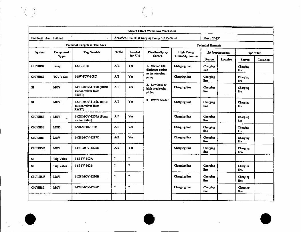
INDIRECT EFFECTS W ALKDOWN WORKSHEET
Building: 17 (AB) Elevation: 2'-13' Cubicle/Section: 17-1 C (Charging Pump 1C Cubicle)
POTENTIAL HAZARDS/POSTULATED EFFECTS
Potential Hazards Postulated Effect
Flooding/Spray Source(s)
.
-High Temperature/Humidity Sources (High Energy Lines only)
Pipe Whip Source(s) (High Energy Lines only) .
·--
Jet Impingement Source(s) (High Energy Lines only)
Comments:
Conclusions/ Actions: ..
•••

/
Indirect Effect Walkdown Worksheet
Building: Aux, Building Area/Sec.: 17-lC (Charging Pump lC Cubicle) Elev,: 2'-13'
Potential Targets In The Area Potential Hazards
System Component Tag Number Train Needed Flooding/Spray High Temp/ Jet Impingement Pipe Whip Type· rorSD? Soun:e Humidity Soun:e
Soun:e Location Source Location
CB/HHSI Pump 1-CH-P-lC A/B Yea 1. Suction and Charging line Charging Charging diacharge piping line line to the charging .
CB/HHSI TCVValve 1-SW-TCV-108C A/B Yea pump Charging line Charging Charging line line
2. Low head to SI MOV 1-CH-MOV-111SB (HHSI A/B Yes high head recirc. Charging line Charging Charging
111ction valvea from piping line line RWST)
·3. RWST header .
SI MOV 1-CH-MOV-111SD (HHSI A/B Yes Charging line Charging Charging mction valves from line line RWST)
CB/HHSI MOV 1-CH-MOV-1270A (Pump A/B Yes Charging line Charging Charging ·:.-auction valve) line line
CB/HHSI MOD 1-VS-M0D-101C A/B Yes Charging line Charging Charging line line
CH/HnlS MOV 1-CH-MOV-1287C A/B Yes Charging line Charging Charging line line
CB/HHSI? MOV ·1-ei1-MOV-127SC A/B Yea Charging line Charging Charging line line
SI Trip Valve . 1-SI-TV-102A ? ?
SI Trip Valve 1-SI-TV-102B ? ? Chsrging line Charging Charging line line
CB/HHSI? MOV 1-CH-MOV-1270B ? ? Charging line Charging Charging line line
CH/HHSI MOV 1-CH-MOV-1286C ? ? Charging line Charging - Charging line line
•••

/ ' ·,.
FIGURE·1: SURRY AUXILIARY BUILDING 21-0 11 ZONE KEY PLAN REV. 8
AB-2A ll \
RC-3B
CJ)
---=-=...
·--
,, ~,---1----1
l·GH -P-ltl
17 - !t 6 U I Co" .\o-i,1r{let1"t ?~ n . Ii----__,
'5 e. c \-\;on 11
-1-c11-i'-IA
::..-------------'--' - - - - - - -· ·--C,t'r'\tr~.e ~rg;:c.or A1..t'f-. {?,-.l, QJ.,·~ ci+ :i_' £.letJ«Qt."'"1 ·
AB-2E
I AB-138 I· 7.375 8.125
\1-ltfs - c.cw
AB-2A CC W Pi..1 r\4 p .$"echi>
9 10
1 Id designates EQ barrier Nies:
· 2\ e ceilin!'.I between AB-28 and. AB-138' is a& barrier
AB-2B
G, e."era..\ .A-~ c,~
(-\1.AJ.. "E->, .. ,\di~ c.>J· ';J..,' f. \ ll V'1t- f:, ~" ""
AB-2F
AB-138
10.75
RC-3B

.
• . • e"•.·. •• .
~ 0
•
'
,,
• a· -,:;__,,.:, ~
1. 1-SW-179 2. 1~S'vV-'i75 3. 1-CH-P-1 C 4. 1-SW-TCV-108C 5. 1-SW-124 6. 1-SW-123 7. 1-CH-500 8. 1-SW-182 9. 1-SW-180 10. 1-CH-P-11 OC 11. 1-CH-249 12. 1-CH-248 13: 1-CH-MOV-1270A 14. 1-CH-469
1-C CHARGING PUMP CUBE 13' ELEV.
15. 1-CH-470 16. 1-Sl-25 17. 1-Sl-26 18. 1-Sl-24 19. 1 rCH-MOV-12708
. 20. 1 '-CH-271 21. 1-SI-TCV-102B 22. 1-S1-TCV-102A 23. 1-CH-270 24. 1-CH-272 25. 1-CH-273 26. 1-CH-276 27. 1-CH-727 28. 1-CH-MOV-1286C
29. 1-CH-MOV-1287C 30. 1-CH-274 31. 1-CH-MOV-1275C __ ;;: 32. 1-CH-LCV-11150\~: 33. 1-CH-458. · -~
.34. 1-CH-LCV-1.115B:~ -~~--..3if_~
r~ ~-- .:·lti {\w':;) 1/ ... ~,---. . v~ ... -~<l.~
fL_hgt'I -~. - ·'!e'::."."j:.: \'=,~Vfa ._;·?~=,·:
;- ~(~f-:
·.·..-
ALARACOMPONENTLOCATORMAP

Bullding: 17 (AB) Elevation: 2'
Potential Hazards
Floooing/Spra:, Source(s)
'
,/.·. i
.i
INDIRECT EFFECTS W ALKDOWN WORKSHEET
Cublcle/Sectlon: 17-AB-CCW (CCW pump section)
POTENTIAL HAZARDS/POSTULATED EFFECTS
Postulated Effect
.
High Temperature/Humidity Sources (High Energy Lines only)
Pipe Whip Source(s) (High Energy Lines only) .
-·--
Jet Impingement Source(s) (High Energy Lines only)
Comments:
Concluslons/ Actions:
•••

Indirect Effect Walkdown Worksheet
Bullding: Am:. Building Area/Sec.: 17-AB-CCW (Component Cooling Pump Area) EJey,: 2'
Potential Targets In The Area Potential Hazards
System Component Tag Number Train Needed F1oodlng/Spray High Tempi Jet Impingement Pipe Whip Type. For SD? Source Humidity Source
Source Location Source Location
ccw Pump 1-CC-P-IA A Ye, I. Suction and Charging line ChatJing Charging diacbarge piping line line to the charging .
ccw Pump 1-CC-P-IB B Ye, pump Charging line ChatJing Charging line line
2. Fire ccw Pump 1-CC-P-IC ? Yes protection Charging line Charging Charging line line
ccw Pump 1-CC-P-ID ? Yes Charging liee Charging Charging line line
·--
Notes:
If no potential ba7.ard i1 identified, state none.
Comments:
•• . . •
_.,..' ',.,<
)
FIGURE·1: SURRY AUXILIARY BUILDING 21-0 11 ZONE KEY PLAN REV. 8
U\
RC-38
AB-2B
AB-2A
1i ,,....__.. __ r-c.H -·P
lfl
11.-1f6 u I (of\·\a-illf('lf?t'lt Ven - ,I------'
'5e.c~on 11
RC-3B
AB-2B
-------------- ·- - - -Ger1er,t..e A-~ 0r - - - - - .. J---------,---r----__J
(X)
Notes:
Av..,;... ~-.1, QJ..,·~ tc-+ 2' £/e~.6,:,.., .
AB-2E
AB-13B I· 7.375 8.125
\1-11-E-c.cw
AB-2A ccW PL-11\4 P .S"ec.hi>
9 10
1Ald designates EQ barrier --. 2,.e ceiling between AB-28 and AB-138 is a9) barrier
G e."era.\ ltrea. 0
f\u)l. ~, .. i\J ir:1 aJ· ';).I E.. I .l<'.V~ fr.;,..,
AB-2F
AB-138
10.75
••

\ \,, _.,. ....
FIGURE ·1: SURRY AUXILIARY BUILDING 21-0 11 ZONE KEY PLAN REV. 8
U\
RC-38
AB-28
·--
AB-2A
1-C.H-P-1 /l
17 __ If{!;, u I Co(\ ·\a-i II r() ~ fl°t 'P~ n - l i----
~ e c ~'o \"'l 11
"l.-(/l-i"-111
RC-38
AB-28
-------~------'-! ·- - - - -Ge,"er.d fh-ea o~
-· - - - -t-----~--,-~-----1 C. v,era.l A-rea. 0 \-
OJ
Notes:
Av.t--. Q.~,, QJ.,·~ ci+ .2.' £,let/lA!~<"'1·
AB-2E
AB-138 I· 7.375 8.125
\l-11-&-c.cw
AB-2A cc w pi_1"" P .5e.£- h0
·I 9 10
1 )Ad designates EQ barrier '2). ceiling between AB-28 and AB-138 is a barrier
Au i. . ~ ,_. i \ d i '2J oJ· :i.1 E-- I ,<.vtX-60..,
AB-2F
AB-138
10.75
••

: .. _·_:._::··
-- ·_.· .
••
.,:. .;:,~~----
1. 1-SW-186 2. 1-SW-185 3. 1-CH-P-1 B 4. 1-SW-TCV-1088 5. 1-SW-126 6. 1-SW-125 7. 1-CH-499 8. 1-SW-183 9. 1-SW-184 10. 1-CH-P-1108
1-B CHARGIN<;i PUMP CUBE 13' ELEV.
11. 1-CH-1269A 12. 1-CH-468 13. 1-CH-467 14. 1-CH-247 15. 1-CH-246 16. 1-CH-262 17. t-CH-261 18. t-Sl-434--19. l-CH-MOV-1863A 20. 1~CH-MOV-18638
ALARA COMPONENT LOCATOR MAP
21. 1-Sl-435 22. 1-CH-MOV-1275E 23. 1-CH-265 24. 1-CH-MOV-12878 25. 1-CH-MOV-12868 26. 1-CH-267 27. t-CH-264 28.1-CH-263 29.1-CH-262.

' "I \.. . i
.. /· /
INDIRECT EFFECTS W ALKDOWN WORKSHEET
Building: 17 (AB) Elention: 2'-13' Cubicle/Section: 17-lC (Charging Pump lC Cubicle)
POTENTIAL HAZARDS/POSTULATED EFFECTS
Potential Hazards
Flooding/Spray Source(s)
. '
High Temperature/Humidity Sources (High Energy Lines only)
Pipe Whip Source(s) (High Energy Lines only) .
·--Jet Impingement Source(s) (High Energy Lines only) ..
Comments:
Conclusions/ Actions:
Postulated Effect
--
..
•
/ '·
\ l / .,./i
Indirect Efl'ect Walkdown Worksheet
Building: Aux. Building Area/Sec.: 17-lC (Charging Pump IC Cubicle) Ele•.: 2'-13'
Potential Targets In The Area Potential Hazards
System Component Tag Number Train Needed Flooding/Spray High Ttmp/ Jet Impingement Pipe Whip Type, rorSD? Source Humidity Source
Source Location Source Location
CH/HHSI Pump 1-CH-P-lC A/B Yes 1. Suction and Charging line Charging Charging diacharge piping line line to the charging .
CH/HHSI TCVValve l-SW-TCV-108C A/B Yea pump Charging line Charging Charging line line
2. Low head to SI MOV l-CH-MOV-1 llSB {HHSI A/B Yea high head reclrc. Charging line Charging Charging
auction valve, from piping line line RWST) --
3. RWST header . SI MOV 1-CH-MOV-1115D (HHSI A/B Yea Charging line Charging Charging
auction valves from line line RWST)
CH/HHSI MOV 1-CH-MOV-1270A (Pump A/B ··--
Yes Charging line Charging Charging auction valve) line line
CH/HHSI MOD 1-VS-MOD-lOlC A/B Yes Charging line Charging Charging line line
CH/HHIS MOV 1-CH-MOV-1287C A/B Yes Charging line Charging Charging line line
CH/HHSI? MOV l-CH-MOV-127SC A/B Yea Charging line Charging Charging line line
SI Trip Valve . l-SI-TV-102A ? ?
SI Trip Valve 1-SI-TV-102B ? ? Charging line Charging Charging line line
CH/HHSI? MOV l-CH-MOV-1270B ? ? Charging line Charging Charging line line
CH/HHSI MOV 1-CH-MOV-1286C ? ? Charging line Charging Charging line line
•

' . ;!
( '·-
FIGURE-1: SURRY AUXILIARY BUILDING 21-0 11 ZONE KEY PLAN REV. 8
U\
RC-3B
AB-2A
- -- - - -=-~--.< ·- .... - - ,,
AB-28 ~..,._,_ _ __, r-C.H-P- 1-CH·t'-IA
(X)
11'
·--
11.- tt 6 U I Co"·\o.,,,f(l~t'l,t f~n - 11----'
~e.chon II :.__ _________ -1-1 - - - -
6t?r'\(.r,i.e /:}~or Av..-J... Q. .. ,,QJ.,';:Ja.+ ;).
1 £1t~Qc",., ·
AB-2E
\ t - /1-& - C.CCAl
AB-2A CC w Pi.1 "4 p .$' e. C. hi>
Notes:
AB-13B I· 7.375 8.125 9 10
1A1d designates EQ barrier A · 2~e ceiling between AB-28 and. AB-138' is aWa barrier
AB-28
G. e."era.\ A-~ o\(-\ I.A i. . '(.i, .... \ \ d i ~ (.'.)_ -~
;i_l f_ \ lf.V~ f:J ,.,, ...,
AB-2F
AB-138
10.75
RC-38
••

.. •··.·. ·.
-:-·
,'
.. -:~·· ·· ...... ~ _..-~·
1. 1-SW-179 2. 1-S'vV-175 3. 1-CH-P-1 C 4. 1-SW-TCV-108C 5. 1-SW-124 6. 1-SW-123 7. 1-CH-500 8. 1-SW-182 9. 1-SW-180 10. 1-CH-P-11 OC 11. 1-CH-249 12. 1-CH-248 13: 1-CH-MOV-1270A 14. 1-CH-469
1-C CHARGING PUMP CUBE 13' ELEV.
15. 1-CH-470 16. 1-Sl-25 17. 1-Sl-26 18. 1-Sl-24 19. hCH-MOV-12708
. 20. 1 ~CH-271 21. 1-SI-TCV-102B 22. 1-S1-TCV-102A 23. 1-CH-270 24. 1-CH-272 25. 1-CH-273 26. 1-CH-276 27. 1-CH-727 28. 1-CH-MOV-1286C
I
\
\
\
\ I
29. 1-CH-MOV-1287C .:-_ \ 30. 1-CH-274 31. 1-CH-MOV-1275C ~5 \ 32. 1-CH-LCV-11150~:f: .~"~. 33. 1-CH-458. · -~
.34. 1-CH-LCV-1.1158;~ I -fi;~i
. -'.~i~ I 1l wf>"'. "~-.:·-~ \' Q;t.h (} VI , ~ . _ .• -~y)
\':.' ._;·:""~:.), i~ :~~;~:.
ALARA COMPONENT LOCATOR MAP

f 'i·
(, ) .. •'
';
/
INDIRECT EFFECTS W ALKDOWN WORKSHEET
Bullding: 17 (AB) Elevation: 2' Cubicle/Section: 17-AB-CCW (CCW pump section)
POTENTIAL HAZARDS/POSTULATED EFFECTS
Potential Hazards Postulated Efl'ect
Floodlng/Spray Source(s)
,,
High Temperature/Humidity Sources (High Energy Lines only)
Pipe Whip Source(s) (High Energy Lines only) . -
--- ...
Jet Impingement Source(s) (High Energy Lines only)
Comments:
.'
Conclusions/ Actions:
•• ' • •

I
' _:}'
Building: Aux. Building
Potential Targets In The Area
System Component Tag Number Type.
ccw Pump 1-CC-P-lA
ccw. Pump l-CC-P-1B
ccw Pump 1-CC-P-lC
ccw Pump l-CC-P-1D
Notes:
If no potential huard 11 identified, llate none.
Comments:
Indirect Effect Walkdown Worksheet
Area/Sec.: 17-AB-CCW (Component Cooling Pump Area) EJey.: 2'
Potmtial Hazards
Train Needed F1oodiq/Spray High Tempi Jet Impingement Pipe Whip for SD? Source Humidity Soun:e
Soun:e Location Soun:e Location
A Yea l. Suction and Charging line Charging Charging dilcharge piping line line to the charging .
B Yea pump Charging line Charging Charging line line
2. Fire ? Yea protection Charging line Charging Charging
line line
? Yea Charging line Charging Charging line line
-
•

_I
( . ( . i' , . r
_./
FIGURE· 1: SURRY AUXILIARY BUILDING 21-0 11 ZONE KEY PLAN REV. 8
U\
RC-38
AB-2A
,; \I __.. __ l·C.H -P
Iil
17--/fG LI I (or1·\0-ir'\('()~t'lt Ven. I __ __.
S e. C n.'o Y) 11
AB-2D RC-38
AB-28
-------T------~----Gefle.r~e fl~of - - - - - -r---------,,--..------'
Av..'f... Q.t.t,QJ.,·~ a.+ ;)_ I £.(i~~,:,'1 ·
AB-2E
AB-138 I· 7.375 8.125
,1_,1-&-c.cw
AB-2A ccw Pi..1"" P .S-ec.hi>
9 10
I s: · Id designates EQ barrier
· ·2 e ceiling between AB-28 and AB-138 is .Q barrier
G e."era.\ It~ 0
j'.\iA)l.~1 .. ,\J;~ a..'t ';J! E.. \ Jf. we. fr,:, ..,
AB-2F
AB-138
10.75
••

,.,-I
INDIRECT EFFECTS W ALKDOWN WORKSHEET
Building: 17 (AB) Elevation: 2' Cubicle/Section: 17-AB (Unit 1 Containment Penetration Section)
POTENTIAL HAZARDS/POSTULATED EFFECTS ,.
Potential Hazards Postulated Effect .
Flooding/Spray Source(s)
.
High Temperature/Humidity Sources (High Energy Lines only)
Pipe Whip Source(s) (High Energy Lines only) .
Jet Impingement Source(s) (High Energy Lines only)
Comments: .
Conclusions/ Actions:
•

/ ', I
,
Indirect Effect Walkdown Worksheet
Building: Aux. Building Area/Sec,: 17-AB (Unit 1 Containment Penetration Area) Flu.: 2'
Potential Targets in The Area Potential Hazank
System Component Tag Number Train Needed F1ooding/Spray High Temp/ Jet Impingement Pipe Whip Type For SD7 Source Humidity Source
Soun:e Location Source Location
SI MOV 1-SI-MOV-1867C (HHSI ? Ye1 1. Suction and Charging line Charging Charging to cold legs) diacha[J!e piping line line
SI ~ov 1-SI-MOV-18670 (HHSI ? Yen to the charging pump Charging ·tine Charging Charging
to cold legs) line line 2. Low head to
SI MOV 1-SI-MOV-1869A (HHSI ? Yen high head recirc. Charging line Charging Charging to hot legs) piping line line
SI MOV l-SI-MOV-1869B (HHSI ? Yes 3. Fire
Charging line Charging Charging to hot legs)
. line line protection line
SI MOV 1-SI-MOV-1842 (alt. ? YH Charging line Charging Charging HHSI to cold leg) line line
cc TV ·--- 1-CC-TV-109A (CCW ? Yes Charging line Charging Charging retum valves from RHR line line HEX)
cc MOV 1-CC-TV-109B ? Yea Charging line Charging Charging line -- line
SI Men. Valve 1-CH-728 (charring cross connect valve)
Notes:
If no potential h117.!1ni is Identified, ltste none.
• •

I .· .. ,
r \ ~. / i ./
FIGURE· 1: SURRY AUXILIARY BUILDING 21-011 ZONE KEY PLAN REV. 8
AB-2A AB-2D ,(,.,. _.,\ ; U\
RC-38 . 0'""~ ?· \ \ ·~·'· . < , ,., . Ci.. \-, ,.,
( ~(\~ ,. ,f\J.l'- • ,,iii:,<.
a,
Notes:
AB-28
·--
17 -It b ,. \ ~
1 r,l',t,7r1 L ·,~en .. L) I l.. o r1 u ' , ,. ' 1::. I
,,/ .. \ 1,..~-r. -~) ~-' \ · _.. f I
AB-138 I· 7.375
j , ,
I·~- rl - riP
8.125
_,~ r, ~,
·l..(fi·l~-111
\ 1 - 4 G -- t c: /AJ
AB-2A
9 10
1Ald designates EQ barrier . · 2~e ceiling between ~'B-28 and AB-138 is barrier
10.75
1tJ :.
RC-3B
AB-2B
AB-138
••

/ \ ,1
,.J
Building: 17 (AB)
Flooding/Spray Source(s)
Elevation: 2'
Potential Hazards
· ..
) i
INDIRECT EFFECTS WALKDOWN WORKSHEET
Cubicle/Section: 17-AB (Remaining sections of the Auxiliary Building at 2' elevation)
POTENTIAL HAZARDS/POSTULATED EFFECTS
Postulated Effect
High Temperature/Humidity Sources (High Energy Lines only)
.
Pipe Whip Source(s) (High Energy Lines only) --
Jet Impingement Source(s) (High Energy Lines only)
Comments:
Conclusions/ Actions:
• • •

,· ,, )
Indirect Effect WaJkdown Worksheet
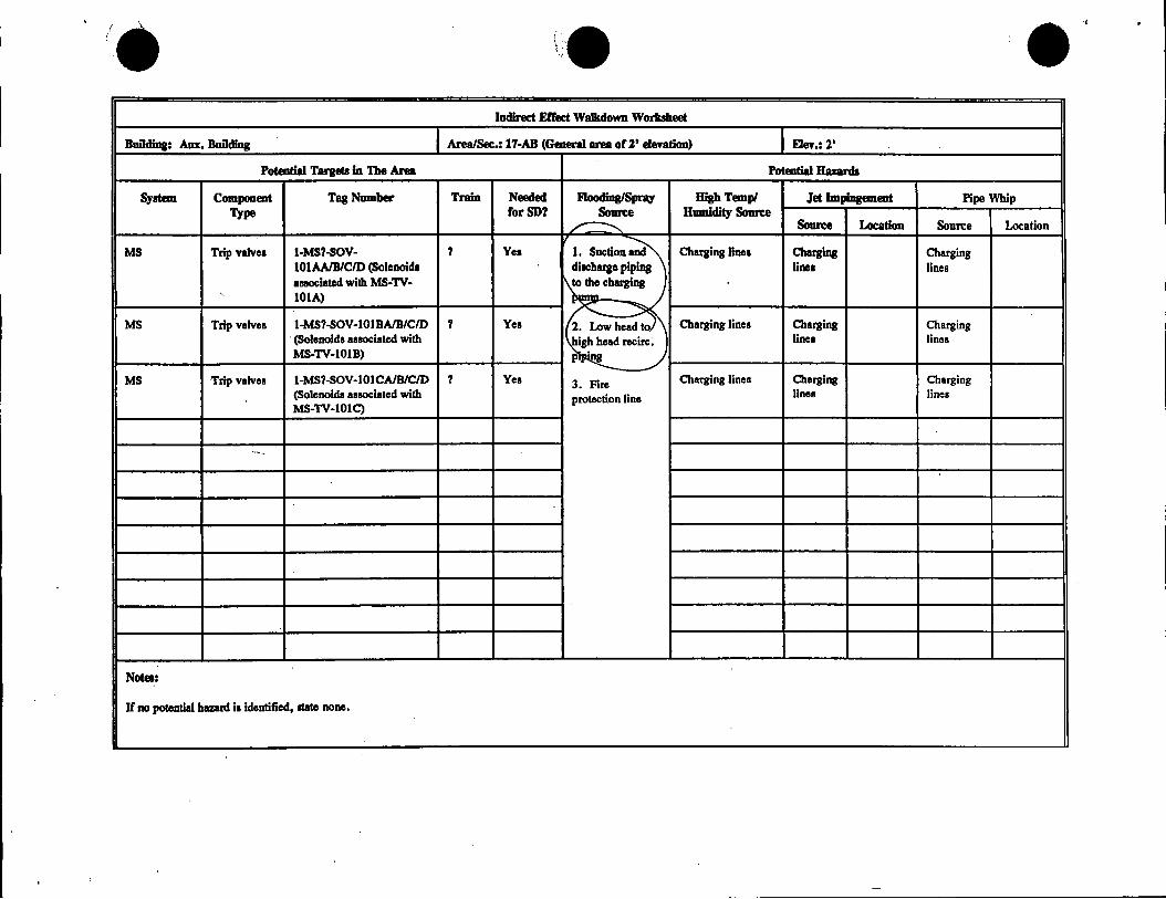
BuDding: Am:. Building Area/Sec.: 17-AB (General area orl' ele-ration) Ele-r.: 2'
Potential Targets In The Area Potential Hazards
System Component Tag Nmnber Train Needed F1ooding/Spray High Temp/ Jet Impingement Pipe Whip Type forSD7 Source Hmmdity Source
~ Source Location Source Location
MS Trip v1lve1 1-MS?-SOV- ? Yee I. Suction~ Charging line1 Chqing Charging IOIAA/B/C/D (Solenoids dlscfwae piping line1 lines auoclated with MS-TV-
~~ IOIA)
iMMm MS Trip valve• 1-MS?-SO'V-lOIBA/B/C/D ? Yea Charging lines Charging Charging (Solenoids aa110Ciated with ead recite. line1 lines MS-TV-lOIB) ..)
-MS Trip valve• 1-MS?-SOV-lOlCA/B/C/D ? Yee 3. Fire Charging lines Charging Charging
(Solenoids aeeociated with protection line line• lines MS-TV-lOlC)
·---
Notes:
If no potentilll hazard ii identified, llato none .
•
/ \, ' -~ \ '. ,'
''\ ... / I /
FIGURE 1: SURRY AUXILIARY BUILDING 2'-0 11 ZONE KEY PLAN REV. 8
U\
RC-3B
AB-28
AB-2A
',1 ,, _,__--1 1-GH -P
l/\
17 __ !ff?., U I (of\ ·\0-ir1r<H~t'l·f 'Pe. rt - l __ __,
s e c \-\:'on · 11
"l-(11-i"--111
--------~---~""""-1 ·- - - -6€'r'l(,rt:l-e /'.}m:c..o\-,
a, A\A-;... ~ .. l,QJ.,·~ a.+ , ..2.' £,le~Q,......, ·
Notes:
AB-2E
AB-138 I· ·7,375
~Id designates EQ barrier
8.125
\1- 11-& _ c.cw
AB-2A
9 10
• .~e ceiling between ~B-28 and AB-138' is Q barrier
AB-28
G e.l'\€ra..\ ./tref.!. 0 \
(\ ,., i.: t~, ... ,\d i,:j oJ· ;,_' f. \ JI. V<f,f. 6 •."> ..-,
AB-2F
AB-138
10.75
RC-38
••

•
··· ... ;.._.,_·.--""
.. . (, . . ·-·
NON-REGEN and SEAL WATER HEAT EXCHANGER ROOM G-14, 2' ELEV.
1. 2-CH-E-2 2._2~H-160 S. 2-CH-159 4. 2-CH-161 5. 2-CH-162 6. 2-CH-164 7. 2-CH-163
- 8. 2-CH-445 9. 2-CH-PCV-2145 10. 2-CH-MOV-~73 11. 2-CH-165 12. 2-CH-231 13. 2-CH-233 14. 2-CH-232 15. 2-CH-166 16. 2-CH-E-1
17. 1-CH-E-1 . 18. i-CC-444 · 19. 1-CH-233 20. 1-CH-231 21. 1-CH-MOV-1373 22. 1-CH-232 23. 1-CH-445 24. 1-CH-:163 25. · 1-CH-165 26. 1'-CH-PCV-1145 27. 1-CH-164 28. 1-CH-162 29. 1-CH-160 30. 1-CH-161 31. 1-CH-E-2 32. 1-CH-166
VALVES liQI SHOiYH 1-CH-150 1-CH-151
. 1-CH-152 1-CH-153 1-CH-154 1-CH-155 1-CH-156 1-CH-159 1-CH-234 1-CH-235 1-CH-393 2-CC-441 2-CH-150 2-CH-151 2-CH-152 2-CH-153 2-CH-154 2-CH-155 2-CH-156 2-CH-159 2-CH-234 2-CH-235 2-CH-393
ALARA COMPONENT LOCATOR MAP

... ,..
\ /:
,/
INDIRECT EFFECTS W ALKDOWN WORKSHEET
Building: 17 (AB) Elevation: 2'-13' Cubicle/Section: 17-lA (Charging Pump lA ·Cubicle)
POTENTIAL HAZARDS/POSTULATED EFFECTS
Potential Hazards Postulated Effect
Flooding/Spray Source(s) .
,-
High Temperature/Humidity Sources (High Energy Lines only)
Pipe Whip Source(s) (High Energy Lines only)
·---
Jet Impingement Source(s) (High Energy Lines only)
Comments:
Conclusions/ Actions:
-
•

•,·';,:, ..
.l) \ '1(/)
Building: Am, Building
Potential Targets In The Area
System Component Tag Number Type
CH/HHSI Pump 1-CH-P-lA
SW Temp. 1-SW-TCV-108A Control Valve
CH/HHSI MOV 1-CH-MOV-1275A
CH/HHSI MOV l-CH-MOV-1287A
CH/HHSI MOV 1-CH-MOV-1267A
-CH/HHSI MOD 1-VS-MOD-lOlA
Notes:
If no potential hazard la identified, state none.
Comments:
Conclusions:
•
r· ) :i .....
Indirect Effect Walkdown Worllsheet
Area/Sec.: 17-tA (Charging Pump tA Cubicle) Eley,: 2'-13'
Potential Hazards
Train Needed Floodlng/Spray High Temp/ Jet Impingement Pipe Whip for SD? Sow,:e Humidity SoDll:e
Sow,:e Location Sow,:e Location
A Yea 1. Suction and Charging line Chal'jing Charging diacharie piping line line to the charging
A Yea pump Charging line Charging Charging line line
2. Low head to
A Yea high head recirc.
Charging line Charging Charging piping line line
A Yea Charging line Charging Charging line line
A Yea Charging line Charging Charging line line
A Yes Charging line Charging Charging line line

·~-~~-,,..···
... 0 •
.,.t,
oa .\
• "
2 vc-: \-J 9rJ.f,I\.O_ .
aJ~. -
0-11\.... L<»fl - 1
' +c-- ~ L-b- ~.J_ 6
• MAiiie.. ..... \'t~~~.,.___::.u..__4{+ .
. S"u.d, 9vt..
No~ S't.tc.ii ~ \Jc-, ·~ p.ws,
~It . .St.tc-\-1 ~ =- L 14 s;: .r
\Jo~ S'u c~ ::= \JC-T 1 ·:
1-A CHARGING PUMP CUBE 13' ELEV.
1. 1-SW-166 2. 1-SW-164 3. 1-CH-P-1A 4. 1-SW-127 5. 1-SW-TCV-108A 6. 1-SW-187 7. 1-SW-128 8'. 1"-SW-188 9. 1"-CH-P-110A
· 10. 1'-CH-390 11 •. 1-CH-466 12. 1-CH-465 t3. t-CH-245
14. 1-CH-MOV-1267A 15. 1-CH-244 16. 1-CH-253 17. 1-CH-MOV-12678 18. 1-CH-MOV-1275A 19. 1-CH-255 20. 1-CH-252 21. 1-CH-254 22. 1-CH-258 23. 1-CH-256 24. 1-CH-MOV-1287A 25. hCH-MOV-1286A
ALARACOMPONENTLOCATORMAP
.•:
'

( })
INDIRECT EFFECTS W ALKDOWN WORKSHEET
Building: 17 (AB) Elevation: 2'-13' Cubicle/Section: 17-lB (Charging Pump 1B Cubicle)
POTENTIAL HAZARDS/POSTULATED EFFECTS
Potential Hazards Postulated Effect
Floodlng/Spray Source(s)
High Temperature/Humidity Sources (High Energy Lines only)
Pipe Whip Source(s) (High Energy Lines only) .
.... _
Jet Impingement Source(s) (High Energy Lines only)
Comments:
Conclusions/ Actions:
•• •

••
...
... -:
SAMPLE SINK RU. (UPPER LEVEL)
27' ELEV.
1. 1-CC-393 2. 1-CC-384 3. 1-CC-383 4. 1°CC-380 5. 1-CC-376 6. 1-CC-382 7. 1-CC-374 8. 1-CC-378 9. 1-CC-3n 1 0. 1-CC-373 11. 1-CC-381 12. 1-CC-375 13. 1-CC-379 14- 1-CC-372
15. 1-CC-386 16. 1-CC-385 17. 2-CC-379 18. 2-CC-375 19. 2-CC-381 20. 2-CC-373 21 . 2-CC-384 22. 2-CC-383 23. 2-CC-374 24. 2-CC-382 25. 2-CC-393 26. 2-CC-376 27. 2-CC-380 28. 2-CC-385 29. 2-CC-372
ALARACOMPONENTLOCATORMAP

SAMPLE SINK RM. (LOVIER LEVEL)
27' ELEV.
1. 1-DA-5 2. 1-DA.;.9 3. 2-VG-8 4. 1-SS-70 5. 1-SS-69 6. 1-SS-66 7. 1-SS-65 8. 1-SS-61 9. 1-SS-74 10. 1-SS-62 11. 1-SS-63 12. 1-SS-64 13. 1-SS-395 14- 1-SS-67
·,. 15. 1--PG.:-go 16. 1-PG-89 17. 2-SS-67 18. 1-SS-394 19. 2-CH-185 20. 2-CH-184 21. 2-CH-186 22. 2:.CH-PCV-2117 23. 2-CH-187 24. t-CH-185 25. r-CH-184 26. t-CH-186 27. 1'-CH-PCV-1117 28. r-CH-187
-~
ALARACOMPONENTLOCATORMAP

\ l
Indirect Effect Walkdown Worksheet
Bullding: Am, Bullding Area/Sec.: 17-lB (Charging Pump 1B Cubicle) Eln.: 2'-13'
Potential Targets In The Area Potential Hazards
System Component Tag Number Train Needed Flooding/Spray High Temp/ Jet Impingement Pipe Whip Type for SD? Source Humidity Source
Source Location Source Location
CH/HHSI Pump l-CH-P-1B B Yea 1. Suction and Charging line - Charging Charging diacharge piping line line to the charging
SI? MOV l-SI-MOV-1863A A Yes pump Charging line Charging Charging . (LHSVHHSI Xtie MOV) line line
2. Low head to SI? MOV l-SI-MOV-1863B B Yea high head recirc. Charging line Charging Charging
(LHSVHHSI Xtle MOV) piping line line
CH/HHSI TCVValve l-SW-TCV-108B B Yea Charging Jine Charging Charging line line
CH MOV l-CH-MOV-1286B (pump A/B Yes Charging line Charging Charging discharge MOV to normal line line injection)
CH MOV I-CH-MOV-1287B (pump A/B Yen Charging line Charging Charging · diacharge MOV to alt. line line Injection)
CH/HHSI MOD l-VS-MOD-101B B Yes Charging line Charging Charging lino line
CH/HHSI MOV l-CH~MOV-1275B B Yes Charging line Charging Charging line line
CH/HHSI MOV 1-CH-MOV-1269A B ? Charging line Charging Charging line line
•

--'( ·:-)
',. ··"
FIGURE ·1: SURRY AUXILIARY BUILDING 2'-0 11 ZONE KEY PLAN REV. 8
U\
RC-38
AB-28
--
AB-2A
,1 11_,_ _ _,
1-C.H -PIP
11 .- !f G U I (ot"l·\0-ir1r<H~r1+ ?e.n - l __ _.
Sec K.'on 11
RC-38
AB-28
-------.....---------1 - - - -Gf,'ltr.i.e ~reao\--
-· -- - - .i------·----,.--r------1 G e.1"1€ra.\ .ltrea. 0 ~
(X) A"-l"f... Q, .. ,,QJ.,·~l'.(,+ ;}_ I £. ( <'. 1/t:<t ~ <""1 '
AB-2E
AB-138 I·
7.375
1 d designates EQ barder
8.125
\ 1- 11-& _ c.cw
AB-2A ccw Pi.1 Mr .$"ec.hi>
9 10
Nls: '2} e ceiling between ~B-28 and AB-138 is a barrier
r\ iA j_: \St.Ai\ J i':.J oJ· ;i_' t°- \ JI.VP- t, 0 .-,
AB-2F
AB-138
10.75
••

• . · ... ·
.:· . ·.
·-....:~-
1. 1-SW-186 2. 1-SW-185 3. 1-CH-P-18 4. 1-SW-TCV-1088 5. 1-SW-126 6. 1-SW-125 7. 1-CH-499 8. 1-SW-183 9. 1-SW-184 10. 1-CH-P-1108
1-8 CHARGING PUMP CUBE 13' ELEV.
11. 1-CH-1269A 12. 1-CH468 13. 1-CH-467 14. 1-rCH-24 7
. 15. 1-CH-246 16. t-CH-262 17. 1-CH-261 18. t-Sl-434. 19. 1"-CH-MOV-1863A 20. 1"-CH-MOV-18638
ALARA COMPONENT LOCATOR MAP
21. 1-Sl-435 22. 1-CH-MOV-1275E 23. 1-CH-265 24. 1-CH-MOV-12878 25. 1-CH-MOV-128~8 26. 1-CH-267 27.1"-CH-264 28.1-CH-263 29. 1-CH-262

/ ::\ \. ) t )
: INDIRECT EFFECTS W ALKDOWN WORKSHEET
Building: 17 (AB) Elevation: 2'-13' Cubicle/Section: 17-lC (Charging Pump lC Cubicle)
POTENTIAL HAZARDS/POSTULATED EFFECTS
Potential Hazards Postulated Effect . ,.
Flooding/Spray Source(s)
High Temperature/Humidity Sources (High Energy Lines only)
Pipe Whip Source(s) (High Energy Lines only) .
Jet Impingement Soutte(s) (High Energy Lines only)
Comments:
Conclusions/ Actions:
•

r' (.
(
\ . ·i j
BuDding: Aux. BuDding
Potential Targets la The Area
System Component TqNumber Type_
CH/HHSI Pump 1-CH-P-IC
CH/HHSI TC'IValve. l-SW-TCV-108C
SI MOV I-CH-MOV-11158 (HHSI 1Uction valve• from RWS'I)
SI MOV I-CH-MOV-l 115D (HHSI auction valves from RWS'I)
CH/HHSI MOV l-CH-MOV-1270A (Pump ·-- auction valve)
CH/HHSI MOD 1-VS-MOD-IOIC
CH/HHIS MOV l-CH-MOV-1287C
CH/HHSI? MOV 1-CH-MOV-1275C
SI Trip Valve l-SI-TV-102A
SI Trip Valve 1-SI-TV-1028
CH/HHSI? MOV 1-CH-MOV-12708
CH/HHSI MOV -l-CH-MOV-1286C
•
Indirect Effect Walkdown Worksheet
Area/Sec.: 17-tC (Cllarplg Pump IC Cnblcle) fley.: 2'-13'
Potential Hazanb
Train Needed nooding/Spray High Tempi J~ Impingement Pipe Whip rorSD? Source Hmnldity Source
Source Location Source Location
A/8 Ye1 I. Suction and Charging line Chargina Charging discharge piping line line to the charging
Charging llne A/8 Yes pump Charging Charging line ..
line 2. Low head to
A/8 Yee high head recirc. Charging line Charging Charging piping line line
A/B Yee 3. RWST header Charging lfne Charging Charging line line
A/8 Yes Charging line Charging Charging line line
A/8 Yes Charging line Charging Ch~rging line line
A/8 Yee Charging line Charging Charging line line
A/8 Ye1 Charging line Charging Charging line line
? ?
? ? Chargiq line Charging Charging line line
? ? Charging line Charging Charging line line
? ? Charging line Charging Charging line line
•

r.·.' \ / i \ . }
FIGURE.1: SURRY AUXILIARY BUILDING 21-0 11 ZONE KEY PLAN REV. 8
U\
RC-38
AB-2B
AB-2A
'i ~.--'--~
1-C.H-Plfl
1 II
:....-----------'-t - - - - - - -· ·-C, er1 er 4-e f} r&;c. 0 \"'
a, Au.t,.. Q,u,(U.,·~ a+ ;)_ I £.(tvi:,,t~t."''1 '
AB-2E
\ 1- 11--& - c.cw
AB-2A CCW Pa.JI\" p _s"et:.ho
AB-138 I· 7.375 8.125 9 10
Notes: 1 Id designates EQ barrier . -
. .
~ ;2 e ceiling between AB-28 and AB-138' is & barrier
AB-28
C. e."era..\ .A-rea. 0 ~
f\ ,_. j_ , "E> I.A \ \ ,J j ~ (.".)J·
;( f-. \ .l{(/4'(. t,.,.., AB-2F
AB-138
10.75
RC-38

• ·.- ·.··.
/
•
..
:::,'··
. ~
0
• ..
1. 1-SW-179 2. 1-S'vV-,75 3. 1-CH-P-1C
----~-----~-<F-1J-)S'f
rflM-- . ,lw_r.
~
1-C CHARGING PUMP CUBE 13' ELEV.
15. 1-CH-470 16. 1-Sl-25 17. 1-Sl-26
4. 1-SW-TCV-108C 18. 1-Sl-24 . 5. 1-SW-124 19. f·CH-MOV-12706
20. 1-CH-271 6. 1-SW-123 7. 1-CH-500 8. 1-SW-182 9. 1-SW-180 10. 1-CH-P-110C 11. 1-CH-249 12. 1-CH-248 13: 1-CH-MOV-1270A 14. 1-CH-469
21. 1-SI-TCV-102B 22. 1-S1-TCV-102A 23. 1-CH-270 24. 1-CH-272 25. 1-CH-273 26. 1-CH-276 27. 1-CH-727 28. 1-CH-MOV·1286C
29. 1-CH-MOV-12870 30. 1-CH-274 31. 1-CH-MOV-1275C · ··: 32. 1-CH-LCV-111 SD~ 5('
.:,~"-·
33. 1-CH-458. · ~: .34. 1-CH-LCV-1.115B~M
.:!~ . . -~~-tr"~
Li" t).~.:·~ fl."'~ ·'~ ·, ---~~ \' VV !L }1 '7 V' v• . < • - -l'e:~~)
\',, () \U'- . . . ~:-. ': . ;· :\·~t-':.
ALARACOMPONENTLOCATORMAP

(
INDIRECT EFFECTS W ALKDOWN WORKSHEET
Building: 17 (AB) Elevation: 2' Cubicle/Section: 17-AB..CCW (CCW pump section)
POTENTIAL HAZARDS/POSTULATED EFFECTS
Potential Hazards Postulated Effect .
Floodlng/Spra1 Source(s)
,.
High Temperature/Humidity Sourcei (High Energy Lines only)
Pipe Whip Source(s) (High Energy Lines only) .
·--
Jet Impingement Source(s) (High Energy Lina only)
Comments:
Conclusions/ Actions:

(
Indirect Effect Walkdown Worksheet
Building: Aux, Building Area/Sec,: 17-AB-CCW (Component Cooling Pump Area) me..:2'
Potential Targets In The Area Potential Hazards
System Component Tag Number Train Needed Flooding/Spray High Tempi Jet Impingement Pipe Whip Type· rorSD? Source Humidity Source
Source Location Source Location
ccw PUmp 1-CC-P-IA .A Yee I. Suction and Charging line Charging Charging dlachaqie piping lino line to the chaqiing
ccw PUmp l-CC-P-18 B Yee pump Charging line Chaqilng Charging line line
2. Fire ccw Pump 1-CC-P-lC ? Yea protection Charging line Charging Charging
line line
ccw Pump l-CC-P-1D ? Yea Charging line Charging .. Charging lino line
Notes:
If no potential hazard i1 Identified, ltate none.
Comments:

'{. /. '.[ .
FIGURE 1: SURRY AUXILIARY BUILDING 2'··011 ZONE KEY PLAN REV. 8
U\
RC-3B
AB~2B
AB-2A
1-CH-Plfl
17 --If G l.J I Cor1·\0-i,1f()~t1t 'Pen - ,---
Se. c \-\..on 11
AB-2D
••
RC-3B
AB-28
------------ - - - -C,er\tr"'l ffr~ o} - - - - . ..---------,--,--------'
a, Av..;... Q,..t,QJ.1~a.+ ;2.
1 £,le~~"""'·
Notes:
AB-2E
AB-138 I· 7.375
1) Bold designates EQ barrier
8.125
\1- tt& - c.cw
AB-2A CCW fiJM p .$"echo
9 10
?) The ceilina between AB-28 and AB-138 is an EQ barrier
G e."era..\ A-r0t. 0
f\u)l. ~, .. ,\Ji~ a..-\-;/ E:. \.ilv~ tJ,::,...,
AB-2F
--
AB-138
10.75

INDIRECT EFFECTS W ALKDOWN WORKSHEET
Building: 17 (AB) Elevation: 2' Cubicle/Section: 17-AB (Unit 1 Containment Penetration Section)
POTENTIAL HAZARDS/POSTULATED EFFECTS
Potential Hazards Postulated Effect
Floodlng/Spray Source(s)
High Temperature/HumlditJ Sources (High Energy Lines only)
Pipe Whip Source(s) (High Energy Lines only)
·--
Jet Impingement Source(s) (High Energy Lines only) ..
Comments:
Concluslons/ Actions:

• \
Indirect Effect Walkdown Worksheet
Building: Amr. Building Area/Sec.: 17-AB (Unit 1 Containment Penetration Area) EleY,: 2'
Potential Targets In The Area Potential Hazard,
Systan Component TagNnmber Train Needed Flooding/Spray High Temp/ Jet Impingement Pipe Whip Type for SD? Soun:e Humidity Source
Source Location Sonrce Location
SI MOV 1-SI-MOV-1867C (HHSI ? Ye1 1. Suction and Charging line Charging Charging to cold leg1) dlachuJe piping line line
SI MOV l-SI-MOV-18670 (HHSI ? Ye1 to the charging puq, Charging line Charging Charging
to cold legs) ·, line line
2. Low head to SI MOV l-SI-MOV-1869A (HHSI ? Yes high head recirc. Charging line Charging Charging
to hot legs) piping line line
SI MOV l-SI-MOV-1869B (HHSI ? Yes 3. Fire
Charging line Charging · Charging to hot leg1)
protection line line line
SI MOV l-SI-MOV-1842 (alt. ? Yes Charging line Charging Charging HHSI to cold leg) line line
cc TV ·-- l-CC-TV-l09A (CCW ? Yes Charging line Charging Charging renim valve• from RHR line line HEX)
cc MOV l-CC-TV-109B ? Yes Charging line Charging Charging line line
SI Man. Valve l-CH-728 (charging cron connect valve)
Notes:
If no potential haunt is identified, ltate none.

l I \.
FIGURE· 1 : SURRY AUXILIARY BUILDING 21-0 11 ZONE KEY PLAN REV. 8
U\
RC-3B
(X)
Notes:
AB-2A
AB-28
--
17 -If 6 LJ j (of) \L1,,,{'0t?.t1t n:~n ·
/ ~ ,;• ,. \ ··t.,. ....... () ., t
(1t",\(1·~.t 1_\q}~ ,-~ .
11',•f. r, ... , ... t)_ :",~·) '( ;. .-, I f~ { ,2 l,1 ~:< ,~) ,.- .. ,
-- -AB-2E
i 'I
I· C.:. i, - f' · i~
il
AB-138 I·
7.375 8.125
1) Bold designates EQ barrier
AB-2D .,, \ {\ ,,,CL i
11' "\ ? \ . . .,. '< ,., 't. 1..,c-, (\I!. ,; t- L. ,,ti '- ,11 '(\'.). -;:: \ ii. ;.1 •
AB-28
C, e. .. , ~- r o .. \ .fl r :/a_ !..""\·
\ 1 - 4 G -- t c.. w
AB-2A
(\ ', i F, l • ; \ .J ; '~'.:f ' )_ 'i .> I:. I ,•.,..x ti 4 •. ,
AB-2F
I AB-138
9 10 10.75
2) The ceiling between ~-S-28 and AB-138 is an EQ barrier
•••
RC-3B

,,.--.--.. ! \·
INDIRECT EFFECTS W ALKDOWN WORKSHEET
BuUding: 17 (AB) Elevation: 2' Cubicle/Section: 17-AB (Remaining sections of the Auxiliary Building at 2' elevation)
POTENTIAL HAZARDS/POSTULATED EFFECTS
Potential Hazards Postulated Effect
Floodlng/Spray Source(s)
'
High Temperature/Humidity Sources (High Energy Lines only)
Pipe Whip Source(s) (High Energy Lines only)
--
Jet Impingement Source(s) .(High Energy Lines only)
Comments:
Concluslons/ Actions:
\.:
Indirect Effect Walkdown Woruheet
Buildlng: Am. Building Area/Sec.: 17-AB (Geaeral area on• eleYation) Eln.: 1'
Potential Targets In The Area Potential Hazards
System Component Tag Number Train Needed Flooding/Spray High Tempi Jet Impiqemeot Pipe Whip Type forSD'l Source Humidity Source
~ Source Location Source Location
MS Trip valves 1-MS?-SOV- ? Yea 1. Suction~ Charging line• Chargtn, Charging lOlAA/B/C/D (Solenoid, dlechaqe piptn, line• lines aeaociated wilh MS-TV-
~~~ ', 101A)
~~m MS Trip valves l-MS?-SOV-101BA/B/C/D ? Yea Charging linen Charging Charging · (Solenoids associated wilh ead recirc; line, lines MS-TV-101B) ~
MS Trip valves 1-MS?-SOV-IOlCA/B/C/D ? Yes 3. Fire Charging lines Charging Charging (Solenoids associated wilh protection line lines lines MS-TV-lOlC)
·--
..
Notes:
If no potential huard i1 identified, llate none,

\
FiGURE 1: SURRY AUXILIARY BUILDING 21-0 11 ZONE KEY PLAN REV. 8
U\
RC-3B
AB-2A
•. - -
AB-2B
I 7 .- /f /?:;, LI I (ol'\·\0-ir'\{'()~~1ff 'Pen - I __ _..
Sec \-1.:'on 11
·1-(/1-t'--//I
-------------'-t - - - -C,er1tr4,e f}r6:;c.o~
a,
Notes:
Av..-;... Q. .. ,,QJ.1·~ a.+ ..2' £lev«~<".., ·
AB-2E
AB-138 I· 7.375 8.125
\1- ,1-& _ c.cw
AB-2A
9 10
1) Bold designates EC barrier 2) The celling between ~B-28 and AB-138' is an EQ barrier
AB-2B
G e.1'1€ra..\ f+rett. D\f-\ i-' f: '(~, .. i\,j;,'21 oJ·
:;.' F. I ~v~ t, ,.,. .,,
AB-2F
AB-138
10.75
••
RC-38

--.... -
, ·. i
•
NON-REGEN and SEAL WATER HEAT EXCHANGER ROOM G-14, 2' ELEV.
1. 2-CH-E-2 2. _2:CH-160 3. 2-CH-159 4. 2-CH-161 5. 2-CH-162 6. 2-CH-164 7. 2-CH-163
· 8. 2-CH-445 9. 2-CH-PCV-2145 10. 2-CH-MOV-2373 11. 2-CH-165 12. 2-CH-231 13. 2-CH-233 14. 2-CH-232 15. 2-CH-166 16. 2-CH-E-1
17. 1-CH-E-1 . VALVES NOI SHOVYN 1-CH-150 1-CH-151 1-CH-152 1-CH-153 1-CH-154 1-CH-155 1-CH-156 1-CH-159 1-CH-234 1-CH-235 1-CH-393 2-CC-441 2-CH-150 2-CH-151 2-CH-152 2-CH-153 2-CH-154 2-CH-155 2-CH-156 2-CH-159 2-CH-234 2-CH-235 2-CH-393
18. 1-CC-444 · 19. 1-CH-233 20. 1-CH-231 21. 1-CH-MOV-1373 22. 1-CH-232 23. 1-CH--445 24. 1-CH-l 63 25. 1-CH-165 26. t-CH-PCV-1145 27. 1-CH-164 28. 1-CH-162 29. 1-CH-160 30. 1-CH-161 31. 1-CH-E-2 32. 1-CH-166
ALARACOMPONENTLOCATORMA!'

\ .• INDIRECT EFFECTS W ALKDOWN WORKSHEET
Building: 17 (AB) Elevation: 45' 10" Cubicle/Section: 17-AB (Aux. Building at 45' 10" elevation)
POTENTIAL HAZARDS/POSTULATED EFFECTS
Potential Hazards Postulated Effect
Flooding/Spray Source(s)
' High Temperature/Humidity Sources (High Energy Line5 only)
Pipe Whip Source(s) (High Energy Lines only)
·--
Jet Impingement Source(s) (High Energy Lines only)
Comments:
Conclusions/ Actions:

(
Indirect Effect Walkdown Worksheet
Bullding: Aux. Building Area/Sec.: 17-AB (General Area od 45' 10" elev.) Elev.: 45' 10"
Potential Targets In The Area Potential Hazards
System Component Tag Number Train Needed Flooding/Spray High Temp/ Jet Impingement Pipe Whip Type for SD? Source Humidity Source
Source Location Source Location
None Fue protection lines
(See note 2)
;,
·--
Notes:
1. If no potential hazard ia identified, state none.
2. Due to the existence of numerous openings, water accumulation in this section of the AB is not possible. Hence, flood-induced damage to the equipment located in this section is not credible. However, floods originating from components located here will propagate to the 2' elevation and can potentially cause significant damage.
3. None of the equipment located here is credited in the PRA model.
Commems: -
-

. .· """,
FIGU.RE 4: SURRY AUXILIARY BUILDING 45'-1 O" ZONE KEY PLAN
RC-188 RC-478
MSVH-27
COLUMN NO.
7.625
Rev. 8
AB-45
9 10.5
Notes:
••
RC-188 RC-478
1) Bold designates EQ barrier

,._ ( \.
INDIRECT EFFECTS W ALKDOWN WORKSHEET
Bulldlng: 17 (AB) Elevation: 27' 6" Cubicle/Section: 17-AB (Aux. Building at 27' 6" elevation)
POTENTIAL HAZARDS/POSTULATED EFFECTS
Potential Hazards Postulated Eff'ect .
Floodlng/Spray Source(s)
High Temperature/Humidity Sources (High Energy Lines only) -
Pipe Whip Source(s) (High Energy Lines only)
·--
Jet Impingement Source(s) (High Energy Lines only)
Comments: ..
Conclusions/ Actions: ,.
i \ • 't
I.. { ·,.
·,.
Indirect Effect Walkdown Worksheet
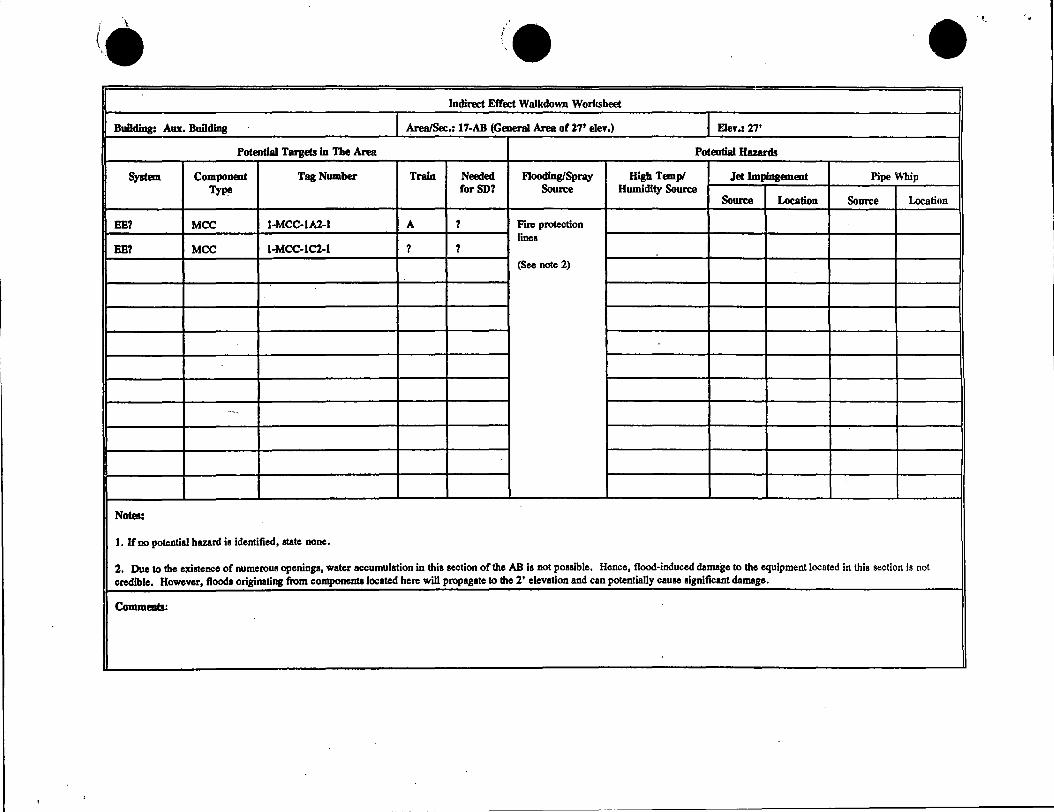
Building: Am:. Building Area/Sec.: 17-AB (General Area or279 eleY.) Eley.: 27'
Potential Target! in The Area Potential Hazards
System Component Tag Number Train Needed F1ooding/Spray High Temp/ Jet Impingement Pipe Whip Type rorSD7 Source Humidity Source
Source Location Source Location
EE? MCC 1-MCC-lAl-1 A ? rll'C protection lines
EE? MCC I-MCC-1C2-1 ? ?
(See note 2)
·---
Notes:
I. It' no potential hazard is identified, state none.
2. Due to the exilltence of numerous openings, water accumulation in this aection of the AB Is not possible. Hence, flood-induced damage to the equipment located in this section is not credible. However, flood• originating from components located here will propagate to the 2' elevation and can potentially cause significant damage.
Comments:

(_··\ \
•,.
...... i •,
•.... ,,
FIGURE. 3: SURRY.AUXILIARY BUILDING 271-611 ZONE KEY PLAN . REV. 8
RC-188 RC-188 AB-27 AB.:27c ·
AB-27 A ---i--- AB-27D
AB 278 AB-27E
.... 0 As.:.21c
AB-27
AB-27F AB-27G
COLUMN NO. AB-138 7.625 8.125 9 10 10.5
Notes: 1) Bold designates EQ barrier 2) The floor and walls between AB-27 and AB-138 are EQ barriers . .

H:GH RAD SAMPLE SINK ROOM ( DRUMMING STATION)
1. 1-LW-533 2. 1-LW-532 3. 1-LW-531 4. 1-LW-538 5. 1-LW-520 6. 1-LW-514 7. 1-LW-517 8. 1 ".'LW-516. 9. 1"-POV-LW-515 10. 1"-LW-534 11. 1"-LW-521 · 12. 1'-LW-P-1 OOA 13. 1·-LW-P-1008
ALARA COMPONENT LOCATOR MAP

.. Clo -
t'.t·
. ~ I iJ
0
'1. • ..,
0
I ,.-
-CC SURGE TANK ROOM [,
1. 1-CC-RV-122 2. 1-CC-RV-123 3. 1-CC-849 4. 1-CC-610 5. 1-CC-611 6 •. , 1-CC-541 7. i-CC-985 8. 1-CC-543
9. 1-CC-544 1 0. 1-CC-986 11 . 1-CC-542 12. 1-CC-545 13. 1-CC-LC-100 14. 1-CC-HCV-100 15. 1-CC-RV-137 16. 1-CC-547 17. 1-CC-546
ALARA COMPONENT LOCATOR MAP
4 .,--:, -~ .. t. . • .,,,_
0
,., d
·f <I . • ~ • q . p ..
•

Ai 0
\ 0
4 ' f •
• "' 0 ... ~
' "
1. 1-CC-356 · · 2. 1-CC-RV-101 A 3. 1-BR-TCV-111A 4. 1-CC-357 5. 1-CC-351 6. 1-CC-RV-101 B 7. 1-BR-TCV-111 B 8. 1-CC-352 9. 1-CC-350 10. -1-CC-355 11 . 1-CC-944 12. 1-CC-812 13. 1-CC-889
Al =
BORON EVAFORATOR ROOM 27 ELEV. LOWER LEVEL
14. 1-BR-EV-1 B . 15. 1-BR-EV-1A 16. 1-BR-461 17. NOT LABELED 18. 1-BR-TK-18 19. 1-BR-TK-1A · 20. ;t -FX-BR-11 0 2L 1-BR-168 22. 1-BR-LCV-104A 23. 1-BR-315 24. 1-BR-166 25. 1-BR-E-2A 26. 1-CC-353
27. 1-CC-354 28. 1-BR-184 29. 1-BR-E-28 30. 1-CC-348 ~1. 1-BR-349 32. 1-BR-183 33. 1-BR-LCV-1048 34. 1-BR-182 35. 1-BR-167
ALARACOlVIPONENTLOCATORMAP
J 4 .. ·,.
4 •\. . •
' A
• C. •
\ • . f .
r
~1.
VALVES NOT SHOWN 1-BR-315 . 1-BR-316 1-BR-321 . 1-CC-686 . 1-CC-97 4 1-CC-975 1-CC-977

.. -. ..
• ,,, . }'1
(J
'~ ) f)
..,
' '"
1. 1-BR-161 2. 1-SR-FCV-102A 3. 1-CC-~30 4. 1-BR-PCV-11'9A 5. 1-BR-310 6. 1-BR-311 7. 1-BR-RV-101A 8 .. 1-BA-155 9. 1-BR-153 10. 1-BR-154 11 . 1-CC-978 12. 1-BR-E-7A 13. 1-BR-152
· 14. 1-BA-TCV-114A 15. 1-BR-151
BORON EVAPORATOR ROOM (UPPER LEVEL)
16. 1-CC-367 17. 1-CC-365 18. 1-BR-159 19. 1-CC-363 20. 1-CC-364 21. 1-BR-150 22. 1-BR-156 23. 1-BR-E-7B 24. 1-CC-359 25. 1-CC-358 26. t-CC-976 27 .. t-BA-162 28. t-BR-326. · 29. t-BR-160 30. 1'-BR-RV-1018
31. 1-BR-327 32.. 1-BR-4n 33. 1-BR-476 34. 1-BR-HCV-1128 35. 1-BR-FCV-1028 36. 1-CC-360 37. 1-CC-47 38. 1-BR-PCV-1098 39. 1-CC-362 40. 1-BR-157 41. 1-CC-359 42. 1-BR-TCV-1148
ALARA COMPONENT LOCATOR MAP
# <1
I"' •
d • 'r •
•
VALVES NOT SHOWN 1-BR-162 1-BR-155
•

..
}~
0
b ~ G) 0
• 0~
0 u.i
0. 0
01.. I>
U-1 VOLUME CONTROL TANK ROOM 27' ELEV. G~17
1. 1-CH-TK-2
VALVES NOT SHOWN 1-CH-199 1-CH-200 1-CH-201 1-CH-202
.ALARACOMPONENTLOCATORMAP
..
.. · ....
1
?o ~ ~-
41 1
~ D..
C
~ 4
/,1,,,,
0 " -v· 0
.-·.-.
}-·~· . _:: .. ·• . ·. ·-~·· . .:-:.·•

,,
.:.
.. 1. • . , -·
SAMPLE SINK RM. (LOVIER LEVEL)
27' ELEV.
1. 1-DA-5 2. 1-DA-9 3. 2-VG-8 4. 1-SS-70 5. 1-SS-69 6. 1-SS-66 7. 1-SS-65 8. 1-SS-61 9. 1-SS-74 10. 1-SS-62 11. 1-SS-63 12. 1-SS-64 13. 1-SS-395 14- 1-SS-67
15. 1--PG.:-go 16. ,-PG-89 17. 2-SS-67
· 18. 1-SS-394 19. 2-CH-185 20. 2-CH-184 21. 2-CH-186 22. 2:..cH-PCV-2117 23. 2-CH-187 24. 1 :-CH-185 25. 1"-CH-184 26. 1·-CH-186 27. 1'-CH-PCV-1117 28. 1'-CH-187
•• " . ~ ., .
"l.
• 0 , .
ALARA COMPONENT LOCATOR MAP _________ ...... ___________ .................. ------.....1 ..