Embed Size (px)
Citation preview
Subscribe to Issue Stories
Hearing Review - March 2010
Issue Stories
Hearing Instrument Technology
Digital Wireless Hearing Aids, Part 1: A Primer
by Francis Kuk, PhD; Bryan Crose; Petri Korhonen, MSc; Thomas Kyhn; Martin Mørkebjerg,MSc; Mike Lind Rank, PhD; Preben Kidmose, PhD; Morten Holm Jensen, PhD; Søren MøllskovLarsen, MSc; and Michael Ungstrup, MSc
Taking an audio signal and transmitting/receiving it digitally is a multi-stage process, with each step influencingthe quality of the transmitted sounds. This article provides a primer about the steps involved in the process forboth near- and far-field transmission of signals.
Digital signal processing has opened up innovative ways where an audio signal can be manipulated. Thisflexibility allows the development of algorithms to improve the sound quality of the audio signal and opens upnew ways in which audio signals can be stored and transmitted. Whereas FM has been the standard of analogwireless transmission used in the hearing aid world, digital is fast becoming the new norm for wirelesstransmission. This paper takes a behind-the-scenes look at some of the basic components of a wireless digitalhearing aid that transmits audio data so that readers may appreciate the complexity of such a system.
All wireless digital hearing aids share the same functional stages shown in Figure 1. All analog audio signalsmust be digitized first through a process called analog-to-digital conversion (ADC). The sampled data is thencoded in a specific way (audio codec) for wireless transmission. An antenna (or transmitter) using radio waves(a form of electromagnetic (EM) waves) is used to transmit these signals, and a receiving antenna (or receiver)paired to the transmitter detects the transmitted signal. The signal is then decoded (audio codec) and sent to thedigital hearing aid for processing. The processed signal then goes through a digital-to-analog conversion(DAC) process again before it is output through the hearing aid receiver.
FIGURE 1. Functional stages of a wireless digital hearing aid.
4/26/2010 Digital Wireless Hearing Aids, Part 1: …
hearingreview.com/…/2010-03_09.asp… 1/14
Each one of these steps can have significant impact on the final power consumption of the hearing aids, thedelay of the transmitted sounds, and the overall sound quality of the signal (to be discussed in Part 2). Thus, tounderstand wireless digital hearing aids, it is necessary that one understands some principles of digital sampling,audio codec (coding and decoding), and transceiver (transmitter and receiver) technology.
Digital Sampling
Francis Kuk, PhD, is director of audiology, and Bryan Crose, BS, and Petri Korhonen, MSc, areresearch engineers at the Widex Office of Research in Clinical Amplification (ORCA), Lisle, Ill, a division ofWidex Hearing Aid Co, Long Island City, NY. Thomas Kyhn, BS, Martin Mørkebjerg, MSc, Mike LindRank, PhD, Preben Kidmose, PhD, Morten Holm Jensen, PhD, Søren Møllskov Larsen, MSc, andMichael Ungstrup, MSc, are research engineers at Widex A/S in Lynge, Denmark.
The process in which a digital system takes a continuous signal (ie, analog), samples it, and quantizes theamplitude so that the signal is discrete in amplitude (ie, no longer continuous) is known as analog-to-digitalconversion (ADC). The digitized signal is a sequence of data samples (strings of “1” and “0”) which representthe finite amplitudes of the audio signal over time.
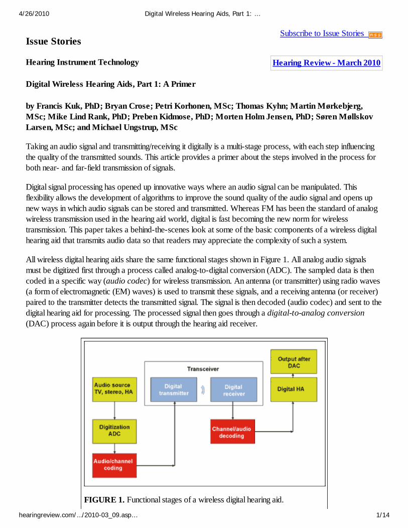
Sampling frequency. The number of times at which we measure the amplitude of an analog signal in onesecond is the sampling frequency or sampling rate. To capture all the frequencies within a signal, thesampling frequency must be at least twice the highest frequency in that signal. For example, if an audio signalhas frequencies up to 8000 Hz, a sampling frequency of 16,000 Hz or higher must be used to sample the audio.Figure 2 shows an example of a 1000 Hz sine wave that is sampled at two different frequencies: 1333 Hz and2000 Hz. As can be seen, the sampling frequency of 1333 Hz incorrectly sampled the 1000 Hz sinusoid as a333 Hz sinusoid (Figure 2a, below left). When the same signal is sampled at 2000 Hz, the original waveform isaccurately reconstructed as a 1000 Hz sine wave (Figure 2b, below right).
FIGURE 2. The effect of sampling frequency on a 1000 Hz waveform. The sample on theleft (A) was reconstructed using a sampling frequency of 1333 Hz, causing distortion,whereas the 2000 Hz sampling frequency produced an accurate rendering of the signal.
Bit depth (or bit resolution). Digital systems use binary digits (0, 1) or bits to represent the amplitudeof the sampled signal. The precision at which the amplitude variations within the audio signal can be reflected is
4/26/2010 Digital Wireless Hearing Aids, Part 1: …
hearingreview.com/…/2010-03_09.asp… 2/14
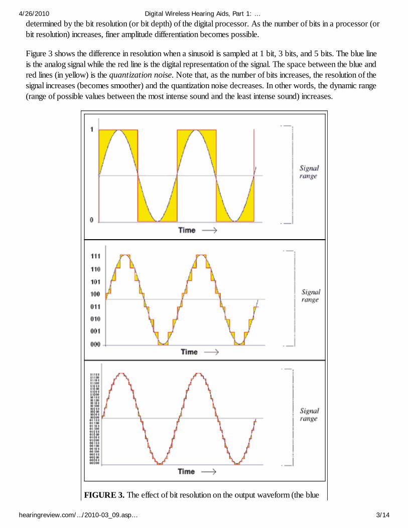
determined by the bit resolution (or bit depth) of the digital processor. As the number of bits in a processor (orbit resolution) increases, finer amplitude differentiation becomes possible.
Figure 3 shows the difference in resolution when a sinusoid is sampled at 1 bit, 3 bits, and 5 bits. The blue lineis the analog signal while the red line is the digital representation of the signal. The space between the blue andred lines (in yellow) is the quantization noise. Note that, as the number of bits increases, the resolution of thesignal increases (becomes smoother) and the quantization noise decreases. In other words, the dynamic range(range of possible values between the most intense sound and the least intense sound) increases.
FIGURE 3. The effect of bit resolution on the output waveform (the blue
4/26/2010 Digital Wireless Hearing Aids, Part 1: …
hearingreview.com/…/2010-03_09.asp… 3/14
line is the original sinusoid). The red line represents the digitized sinusoid.The difference between the red and blue lines (in yellow) is the quantizationnoise.
Perceptually, a signal that is processed with a high bit resolution will sound clearer, sharper, and cleaner thanthe same signal that is processed with a lower bit resolution. One shouldn’t think that more bits are needed torepresent a more intense signal (or fewer bits for a soft sound); however, more bits are needed when loud andsoft sounds are presented together (ie, fluctuations in level) and one is interested in preserving the relativeamplitudes of these sounds (ie, dynamic range).
Sampling trade-offs: current drain. When an analog signal is converted into a digital form, the amountof information (number of bits) or size of the digital signal is a product of the sampling frequency, the bitresolution, and the duration of the sampling. A digital processor that uses a high bit resolution sampling at a highfrequency results in more bits than ones that use a lower bit resolution and/or a lower sampling frequency. Thismeans that more of the nuances of the input signal are available. Perceptually, this corresponds to a less noisysignal with a better sound quality. Unfortunately, more bits also mean more computations, larger memory, andlonger time to transmit. Ultimately, this demands a higher current drain. Thus, a constant challenge for engineersis to seek the highest sampling frequency and the greatest bit resolution without significantly increasing thecurrent drain.
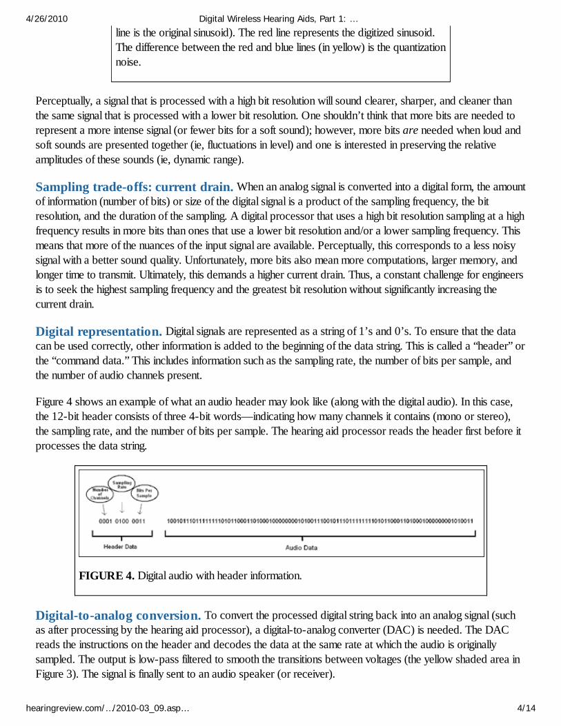
Digital representation. Digital signals are represented as a string of 1’s and 0’s. To ensure that the datacan be used correctly, other information is added to the beginning of the data string. This is called a “header” orthe “command data.” This includes information such as the sampling rate, the number of bits per sample, andthe number of audio channels present.
Figure 4 shows an example of what an audio header may look like (along with the digital audio). In this case,the 12-bit header consists of three 4-bit words—indicating how many channels it contains (mono or stereo),the sampling rate, and the number of bits per sample. The hearing aid processor reads the header first before itprocesses the data string.
FIGURE 4. Digital audio with header information.
Digital-to-analog conversion. To convert the processed digital string back into an analog signal (suchas after processing by the hearing aid processor), a digital-to-analog converter (DAC) is needed. The DACreads the instructions on the header and decodes the data at the same rate at which the audio is originallysampled. The output is low-pass filtered to smooth the transitions between voltages (the yellow shaded area inFigure 3). The signal is finally sent to an audio speaker (or receiver).
4/26/2010 Digital Wireless Hearing Aids, Part 1: …
hearingreview.com/…/2010-03_09.asp… 4/14
Audio Data Compression or Audio Codec
Rationale for data compression. When audio is converted from an analog to a digital format, theresulting size of the digital audio data can be quite large. For example, one minute of stereo audio recorded at asampling frequency of 44,100 Hz (or samples per second) at a 16-bit resolution results in over 84 Mbits ofinformation. This requires 10.5 Mbytes (MB) of storage (1 byte = 8 bits). That’s why an audio CD with acapacity of 783 Mbytes (MB) can hold only 74 minutes of songs.
To increase the number of songs that can be stored on the CD, one can either digitize the songs with a lower bitresolution, or sample them at a lower sampling frequency. Unfortunately, a lower bit resolution will decrease theamplitude resolution of the audio signal and increase the quantization noise. Decreasing the sampling frequencywill limit the range of frequencies that are captured and lose some details of the songs. Thus, neither approachoffers an acceptable solution to reduce the size of the data file and yet maintain the sound quality of the music.
Data compression (or data codec, short for “data coding and decoding”) allows digital data to be stored moreefficiently, thus reducing the amount of physical memory required to store the data. Authors’ Note: Datacompression should not be confused with amplitude compression, which is the compression or reductionof the dynamic range of an audio signal. Unless specifically intended, data compression generally doesnot reduce or alter the amplitude of the audio signal, but it does reduce the physical size (number ofbits) that the audio signal occupies.
The transmission bit rate—or how much data (in number of bits) a transmitter is capable of sending in unit time—is a property of the transmitting channel. It depends on the available power supply, the criterion foracceptable sound quality of the transmitted signal, and also the integrity of the codec that is used to code anddecode the transmitted signal. So, for example, while a higher bit rate usually means more data can betransmitted (and a better sound quality by inference), it does not guarantee sound quality because sound qualityalso depends on how well the codec system works.
How quickly an audio sample is transmitted (or downloaded) is important in the music world. The amount ofdownloading time is related to the size of the file and the bit rate of the transmitting channel. For example, a 4-minute song of 35 MB takes over 9 minutes to download using an average high-speed Internet connection (bitrate of 512 KB). If the same song is compressed using mp3 encoding technique, it is approximately 4 MB insize and takes approximately 1 minute to download. Thus, another reason for data compression (or codec) isto reduce the size of the “load” (or file) so the same data can be transmitted faster within the limits of thetransmission channel without losing its quality.
A digital wireless hearing aid that transmits audio from one hearing aid to the other, or from a TV/cell phone,etc, to the hearing aid, has the same (or more) constraints as a music download. Because of the need foracceptable current consumption, the bit rate of current wireless digital hearing aids is typically lower than thehigh-speed Internet. In order to transmit the online digital audio without any noticeable delays or artifacts, someintelligent means for reducing the size of the audio data file is critical. (Note: this is not a necessary considerationfor transmission of parametric data, such as hearing aid gain settings, because of the relatively small size andnon-redundant nature of such data.)
Audio coding. The various algorithms that are used to code and decode an audio signal are called audiocodec. The choice of a codec is based on several factors, such as the maximum available transmission bit rate,the desired audio quality of the transmitted signal, the complexity of the wireless platform, and the ingenuity of
4/26/2010 Digital Wireless Hearing Aids, Part 1: …
hearingreview.com/…/2010-03_09.asp… 5/14
the design engineers. These decisions affect the effectiveness of the codec.
One can code a signal intelligently so it has good sound quality but fewer bits (thus requiring a lowertransmission bit rate). Conversely, if the codec is not “intelligent” or if the original signal does not have a goodsound quality, no transmission system at any bit rate can improve the sound quality.
There are two components in the audio encoding process: 1) Audio coding which involves “packaging” of theaudio signals to a smaller size, and 2) Channel coding which involves adding error correction codes to handlepotential corrupted data during the transmission. Protocol data, such as header information for data exchange,is also included prior to transmission.
Approaches to audio coding: lossless vs lossy. The objective for audio coding is to reduce the sizeof the audio file without removing pertinent information. Luckily, audio signals have large amounts of redundantinformation. These redundancies may be eliminated without affecting the identity and quality of the signal. Audiocoding takes advantage of this property to reduce the size of the audio files. The two common approaches—lossless and lossy—may be used alone or in combination (these approaches may be used with otherproprietary approaches as well).
Lossless codec. The systems that take advantage of the informational redundancy in audio signals arecalled lossless systems. These systems use “redundancy prediction algorithms” to compile all the redundant orrepeated information in the audio signal. They then store the audio more efficiently with fewer bits but noinformation is lost. For example, the number 454545454545 can be coded as a 12-digit number by thecomputer. But the same number can also be coded as 6(45) to be read as 45 repeated 6 times.
This is the process used when computers compress files into a ZIP file. It is used in applications where exactdata retention—such as computer programs, spreadsheets, computer text, etc—is necessary.
Lossy codec. The systems that take advantage of perceptual redundancy in audio coding are called lossysystems. They use “irrelevance algorithms” which apply existing knowledge of psychoacoustics to aid ineliminating sounds that are outside the normal perceptual limits of the human auditory system. For example, it isknown that, when two sounds are presented simultaneously, the louder sound will exert a masking effect on thesofter sound. The amount of masking depends on the closeness of the spectra of the two sounds. Because ofmasking effects, it is inconsequential perceptually if one does not code the softer sound while a louder one ispresent. Lossy audio coding algorithms are capable of very high data reduction, yet in these systems the outputsignal is not an exact replica of the input signal (even though they may be perceptually identical).
This type of codec is commonly used in mp3 technology. JPEG (Joint Photographic Experts Group)compression is another example of lossy data compression used in the visual domain.
Channel coding. One important consideration when sending any type of data (analog or digital) is thepotential of the introduction of errors into the signal from electromagnetic interference during the transmissionprocess. This is especially pertinent for wireless systems. Consequently, efforts must be made to ensure that thetransmitted data are received correctly.
Channel coding algorithms provide a method to handle transmission errors. To achieve that objective, channelcoding algorithms specify ways to check the accuracy of the received data. They also include additional codesthat specify how errors can be handled.
4/26/2010 Digital Wireless Hearing Aids, Part 1: …
hearingreview.com/…/2010-03_09.asp… 6/14
Because there are no required standards on how these errors must be handled, channel coding algorithms varywidely among manufacturers. Some devices simply ignore and drop the data that are in error; some wait for thecorrect data to be sent; and others can correct the data that are in error. The various approaches can affect therobustness of the transmission and the sound quality of the transmitted signal.
Before sending the encoded digital audio (and the error correction codes), the encoder generates a header tothe data following the protocol for wireless transmission. In this case, the header includes the address of thereceiver, command data, and a data-type identification code that specifies which data are instructions, whichare audio data, and which are error-correction codes. In addition, it also includes information on how to makesure that the transmitted data are correct; and how to handle “errors” if and when they are encountered.
Audio decoding. When a coded audio signal is received, it needs to be decoded so the original informationcan be retrieved. The receiver first examines the header information from the received coded signals so itknows how the received data should be handled. The received data then go through the channel decoder toensure that the transmitted data are correct. Any transmission errors are handled at this channel decoding stageaccording to the error-correction codes of the channel codec. The channel-decoded signal then feeds throughthe audio decoder which unpacks the compressed digital audio data to restore the “original” digital audio.
“Bit-true” vs “non bit-true” decoding. There are two approaches to audio codec: bit-true and nonbit-true. A bit-true codec means the decoder knows the encoder so it can decode the audio faithfully with theleast current drain. Because it knows how the data are coded, it is prepared to handle any “errors” that itencounters during the transmission. A bit-true system is a dedicated system.
A non bit-true codec is an open system that allows multiple manufacturers to produce files that can bedecoded by the same decoder. An example is the codec used in mp3 players. The advantage of a non bit-truesystem is its flexibility, adaptability, and ease of implementation by various manufacturers; it can savedevelopment time and resources. A potential problem is that the quality is not always ensured because differentimplementations are allowed. And because the decoder does not know the encoder, errors that are introducedduring the transmission may not be corrected effectively and/or efficiently. This leads to drop outs andincreased noise, and it may degrade the quality of the transmitted audio.
Wireless Transmission
Why wireless? Wireless allows the transfer of information (or audio data) over distance (from less than a meterto over thousands of miles) without the use of any wires or cables. Although wireless opens up the transmitteddata to potential interference by other signals, the convenience that it offers and the possibility that data can betransferred over a long distance (such as a satellite) make it a desirable tool for data transmission.
The challenge for engineers is to minimize the potential for transmission errors (from interference) while keepingreasonable power consumption. Today, wireless transmission technology is also applied to hearing aids to bringabout improvements in communication performance never before possible.
Vehicles for transmission: Electromagnetic (EM) waves. Wireless transmission is achievedthrough the use of electromagnetic (EM) waves. This is a type of transverse wave which has both an electriccomponent and a magnetic component. EM waves by themselves are not audible unless they are converted toa sound wave (a longitudinal wave). One property of an EM wave is its ease of being modified by another
4/26/2010 Digital Wireless Hearing Aids, Part 1: …
hearingreview.com/…/2010-03_09.asp… 7/14
signal. This makes EM waves excellent carriers of data.
Electromagnetic waves cover a wide range of frequencies. The choice of carrier frequency depends on howmuch information needs to be sent, how much power is available, the transmission distance, how many otherdevices are using that frequency, local laws and regulations, and terrestrial factors such as mountains orbuildings that may be in the path of the transmission. Higher carrier frequencies can carry more information thanlower frequency carriers. On the other hand, lower frequencies require less power for transmission.
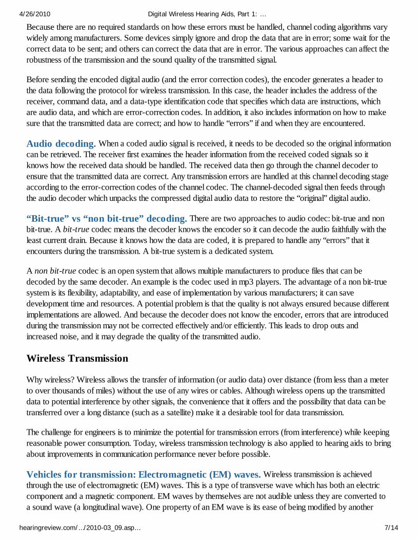
The spectra of electromagnetic waves that are used today can be divided into different categories. Visible lightis one form of electromagnetic waves and it is marked in the center of Figure 5. On the left side of the spectrumare the frequencies for radio transmission (or radio waves). These waves have a longer wavelength (and thuslower frequencies) than light and are commonly used for most types of wireless communication. One can seethat most of the AM and FM radios use frequencies between the 106 and 108 Hz regions.
FIGURE 5. The electromagnetic (EM) spectra, with visible light near the center and mostof our transmission carrier frequencies in the lower/longer frequency regions.
Far-field vs near-field transmission. Traditional wireless transmission systems use an antenna totransmit an EM wave through the air. The farther the wave is from the transmitter, the weaker its strength.However, the rate of decrease of the EM wave amplitude depends on how far the signal propagates.
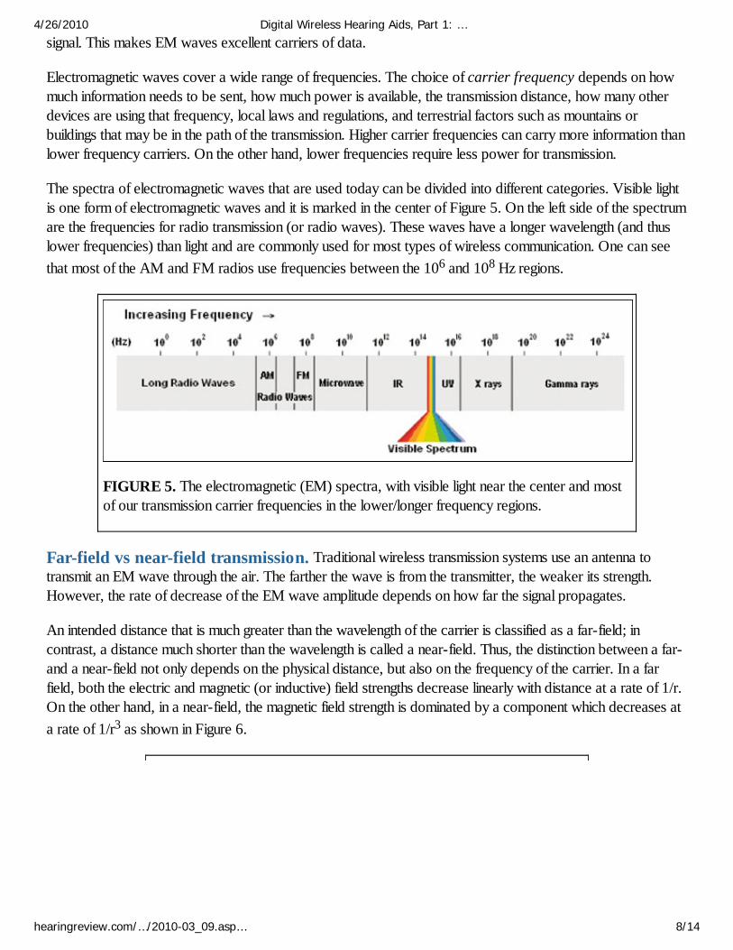
An intended distance that is much greater than the wavelength of the carrier is classified as a far-field; incontrast, a distance much shorter than the wavelength is called a near-field. Thus, the distinction between a far-and a near-field not only depends on the physical distance, but also on the frequency of the carrier. In a farfield, both the electric and magnetic (or inductive) field strengths decrease linearly with distance at a rate of 1/r.On the other hand, in a near-field, the magnetic field strength is dominated by a component which decreases ata rate of 1/r3 as shown in Figure 6.
4/26/2010 Digital Wireless Hearing Aids, Part 1: …
hearingreview.com/…/2010-03_09.asp… 8/14
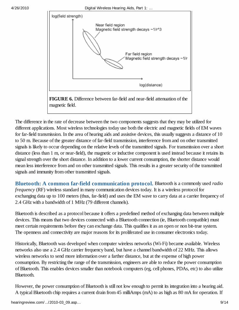
FIGURE 6. Difference between far-field and near-field attenuation of themagnetic field.
The difference in the rate of decrease between the two components suggests that they may be utilized fordifferent applications. Most wireless technologies today use both the electric and magnetic fields of EM wavesfor far-field transmission. In the area of hearing aids and assistive devices, this usually suggests a distance of 10to 50 m. Because of the greater distance of far-field transmission, interference from and on other transmittedsignals is likely to occur depending on the relative levels of the transmitted signals. For transmission over a shortdistance (less than 1 m, or near-field), the magnetic or inductive component is used instead because it retains itssignal strength over the short distance. In addition to a lower current consumption, the shorter distance wouldmean less interference from and on other transmitted signals. This results in a greater security of the transmittedsignals and immunity from other transmitted signals.
Bluetooth: A common far-field communication protocol. Bluetooth is a commonly used radiofrequency (RF) wireless standard in many communication devices today. It is a wireless protocol forexchanging data up to 100 meters (thus, far-field) and uses the EM wave to carry data at a carrier frequency of2.4 GHz with a bandwidth of 1 MHz (79 different channels).
Bluetooth is described as a protocol because it offers a predefined method of exchanging data between multipledevices. This means that two devices connected with a Bluetooth connection (ie, Bluetooth compatible) mustmeet certain requirements before they can exchange data. This qualifies it as an open or non bit-true system.The openness and connectivity are major reasons for its proliferated use in consumer electronics today.
Historically, Bluetooth was developed when computer wireless networks (Wi-Fi) became available. Wirelessnetworks also use a 2.4 GHz carrier frequency band, but have a channel bandwidth of 22 MHz. This allowswireless networks to send more information over a farther distance, but at the expense of high powerconsumption. By restricting the range of the transmission, engineers are able to reduce the power consumptionof Bluetooth. This enables devices smaller than notebook computers (eg, cell phones, PDAs, etc) to also utilizeBluetooth.
However, the power consumption of Bluetooth is still not low enough to permit its integration into a hearing aid.A typical Bluetooth chip requires a current drain from 45 milliAmps (mA) to as high as 80 mA for operation. If
4/26/2010 Digital Wireless Hearing Aids, Part 1: …
hearingreview.com/…/2010-03_09.asp… 9/14
a Bluetooth chip were embedded in a hearing aid that uses a #10 battery (with a capacity of 80 mAh), thebattery would only last 1 to 2 hours before it expires!
Another problem with Bluetooth is the audio delay inherent in the standard Bluetooth audio profile. In creating astandard that is adaptable to many different devices, Bluetooth has to satisfy many procedures to ensure aproper communication link between devices. This delays the immediate transmission of signals. For example, adelay of up to 150 ms may be noted between the direct sound and the transmitted sound from a TV usingBluetooth. When a delayed audio signal is mixed with the direct signal, a poorer sound quality—ranging from a“metallic” sound to an “echo”—may be perceived depending on the amount of delay. Excessive delay, such as150 ms, could lead to a dis-synchrony between the visual and audio signals. Figure 7 shows the perceptualartifacts that may result from mixing direct sounds with transmitted sounds at various delays.
FIGURE 7. The consequences of direct and delayed transmitted signalson the perception of sound. Delays in excess of 10 ms becomeproblematic.
Near-field magnetic induction (NFMI). The limited capacity of today’s hearing aid batteries makes itimpractical to use Bluetooth exclusively for far-field transmission to the hearing aids.
The rapid rate of attenuation of the magnetic field (shown in Figure 6) would suggest high signal strength withina close proximity and low signal strength beyond. This ensures accurate transmission of data between intendeddevices (such as hearing aids). The rapid decay characteristics mean that its signal strength will not be sufficientto interfere with other near-field devices in the environment, nor will it be interfered with by other unintendednear-field devices. A shorter range of transmission will also require a lower carrier frequency, reducing thepower consumption.
This makes magnetic or inductive EM wave an ideal technology to be integrated within hearing aids for near-field or short-range communication. On the other hand, the orientation of the antennae (between the transmitterand the receiver) may affect the sensitivity of the reception. A remote control and wireless CROS hearing aidsare prime examples of this form of technology.
Streamers and relay: A solution that incorporates inductive and Bluetooth. Using an inductive signal forwireless communication between hearing aids makes sense because of the security and low power requirement.
4/26/2010 Digital Wireless Hearing Aids, Part 1: …
hearingreview.com/…/2010-03_09.asp… 10/14
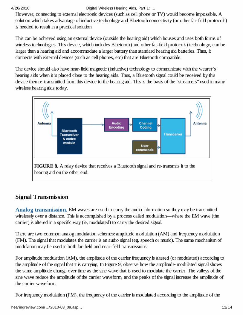
However, connecting to external electronic devices (such as cell phone or TV) would become impossible. Asolution which takes advantage of inductive technology and Bluetooth connectivity (or other far-field protocols)is needed to result in a practical solution.
This can be achieved using an external device (outside the hearing aid) which houses and uses both forms ofwireless technologies. This device, which includes Bluetooth (and other far-field protocols) technology, can belarger than a hearing aid and accommodate a larger battery than standard hearing aid batteries. Thus, itconnects with external devices (such as cell phones, etc) that are Bluetooth compatible.
The device should also have near-field magnetic (inductive) technology to communicate with the wearer’shearing aids when it is placed close to the hearing aids. Thus, a Bluetooth signal could be received by thisdevice then re-transmitted from this device to the hearing aid. This is the basis of the “streamers” used in manywireless hearing aids today.
FIGURE 8. A relay device that receives a Bluetooth signal and re-transmits it to thehearing aid on the other end.
Signal Transmission
Analog transmission. EM waves are used to carry the audio information so they may be transmittedwirelessly over a distance. This is accomplished by a process called modulation—where the EM wave (thecarrier) is altered in a specific way (ie, modulated) to carry the desired signal.
There are two common analog modulation schemes: amplitude modulation (AM) and frequency modulation(FM). The signal that modulates the carrier is an audio signal (eg, speech or music). The same mechanism ofmodulation may be used in both far-field and near-field transmissions.
For amplitude modulation (AM), the amplitude of the carrier frequency is altered (or modulated) according tothe amplitude of the signal that it is carrying. In Figure 9, observe how the amplitude-modulated signal showsthe same amplitude change over time as the sine wave that is used to modulate the carrier. The valleys of thesine wave reduce the amplitude of the carrier waveform, and the peaks of the signal increase the amplitude ofthe carrier waveform.
For frequency modulation (FM), the frequency of the carrier is modulated according to the amplitude of the
4/26/2010 Digital Wireless Hearing Aids, Part 1: …
hearingreview.com/…/2010-03_09.asp… 11/14
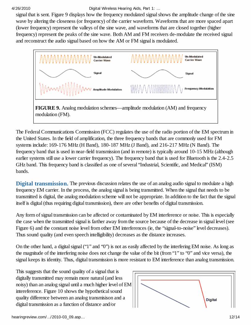
signal that is sent. Figure 9 displays how the frequency modulated signal shows the amplitude change of the sinewave by altering the closeness (or frequency) of the carrier waveform. Waveforms that are more spaced apart(lower frequency) represent the valleys of the sine wave, and waveforms that are closed together (higherfrequency) represent the peaks of the sine wave. Both AM and FM receivers de-modulate the received signaland reconstruct the audio signal based on how the AM or FM signal is modulated.
FIGURE 9. Analog modulation schemes—amplitude modulation (AM) and frequencymodulation (FM).
The Federal Communications Commission (FCC) regulates the use of the radio portion of the EM spectrum inthe United States. In the field of amplification, the three frequency bands that are commonly used for FMsystems include: 169-176 MHz (H Band), 180-187 MHz (J Band), and 216-217 MHz (N Band). Thefrequency band that is used in near-field transmission (and in remote) is typically around 10-15 MHz (althoughearlier systems still use a lower carrier frequency). The frequency band that is used for Bluetooth is the 2.4-2.5GHz band. This frequency band is classified as one of several “Industrial, Scientific, and Medical” (ISM)bands.
Digital transmission. The previous discussion relates the use of an analog audio signal to modulate a highfrequency EM carrier. In the process, the analog signal is being transmitted. When the signal that needs to betransmitted is digital, the analog modulation scheme will not be appropriate. In addition to the fact that the signalitself is digital (thus requiring digital transmission), there are other benefits of digital transmission.
Any form of signal transmission can be affected or contaminated by EM interference or noise. This is especiallythe case when the transmitted signal is farther away from the source because of the decrease in signal level (seeFigure 6) and the constant noise level from other EM interferences (ie, the “signal-to-noise” level decreases).Thus sound quality (and even speech intelligibility) decreases as the distance increases.
On the other hand, a digital signal (“1” and “0”) is not as easily affected by the interfering EM noise. As long asthe magnitude of the interfering noise does not change the value of the bit (from “1” to “0” and vice versa), thesignal keeps its identity. Thus, digital transmission is more resistant to EM interference than analog transmission.
This suggests that the sound quality of a signal that isdigitally transmitted may remain more natural (and lessnoisy) than an analog signal until a much higher level of EMintereference. Figure 10 shows the hypothetical soundquality difference between an analog transmisison and adigital transmission as a function of distance and/or
4/26/2010 Digital Wireless Hearing Aids, Part 1: …
hearingreview.com/…/2010-03_09.asp… 12/14
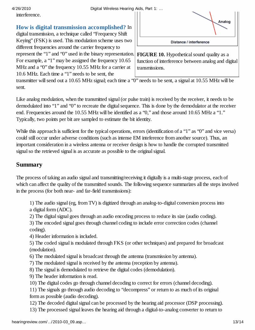
FIGURE 10. Hypothetical sound quality as afunction of interference between analog and digitaltransmissions.
interference.
How is digital transmission accomplished? Indigital transmission, a technique called “Frequency ShiftKeying” (FSK) is used. This modulation scheme uses twodifferent frequencies around the carrier frequency torepresent the “1” and “0” used in the binary representation.For example, a “1” may be assigned the frequency 10.65MHz and a “0” the frequency 10.55 MHz for a carrier at10.6 MHz. Each time a “1” needs to be sent, thetransmitter will send out a 10.65 MHz signal; each time a “0” needs to be sent, a signal at 10.55 MHz will besent.
Like analog modulation, when the transmitted signal (or pulse train) is received by the receiver, it needs to bedemodulated into “1” and “0” to recreate the digital sequence. This is done by the demodulator at the receiverend. Frequencies around the 10.55 MHz will be identified as a “0,” and those around 10.65 MHz a “1.”Typically, two points per bit are sampled to estimate the bit identity.
While this approach is sufficient for the typical operations, errors (identification of a “1” as “0” and vice versa)could still occur under adverse conditions (such as intense EM inteference from another source). Thus, animportant consideration in a wireless antenna or receiver design is how to handle the corrupted transmittedsignal so the retrieved signal is as accurate as possible to the original signal.
Summary
The process of taking an audio signal and transmitting/receiving it digitally is a multi-stage process, each ofwhich can affect the quality of the transmitted sounds. The following sequence summarizes all the steps involvedin the process (for both near- and far-field transmissions):
1) The audio signal (eg, from TV) is digitized through an analog-to-digital conversion process intoa digital form (ADC).2) The digital signal goes through an audio encoding process to reduce its size (audio coding).3) The encoded signal goes through channel coding to include error correction codes (channelcoding).4) Header information is included.5) The coded signal is modulated through FKS (or other techniques) and prepared for broadcast(modulation).6) The modulated signal is broadcast through the antenna (transmission by antenna).7) The modulated signal is received by the antenna (reception by antenna).8) The signal is demodulated to retrieve the digital codes (demodulation).9) The header information is read.10) The digital codes go through channel decoding to correct for errors (channel decoding).11) The signals go through audio decoding to “decompress” or return to as much of its originalform as possible (audio decoding).12) The decoded digital signal can be processed by the hearing aid processor (DSP processing).13) The processed signal leaves the hearing aid through a digital-to-analog converter to return to
4/26/2010 Digital Wireless Hearing Aids, Part 1: …
hearingreview.com/…/2010-03_09.asp… 13/14
its analog form (DAC).
Correspondence can be addressed to HR or Francis Kuk, PhD, at [email protected].
Citation for this article:
Kuk F, Crose B, Korhonen P, Kyhn T, Mørkebjerg M, Rank ML, Kidmose P, Jensen MH, Larsen SM,Ungstrup M. Digital wireless hearing aids, Part 1: A primer. Hearing Review. 2010;17(3):54-67.
Normal Version
4/26/2010 Digital Wireless Hearing Aids, Part 1: …
hearingreview.com/…/2010-03_09.asp… 14/14
This article was submitted to HR by Francis Kuk, PhD,
Petri Korhonen, MSc, and Bryan Crose, BSc, of
Widex ORCA, Lisle, Ill; and Thomas Kyhn, Martin
Mørkebjerg, MS, Mike Lind Rank, PhD, Preben
Kidmose, PhD, Morten Holm Jensen, PhD, Søren
Møllskov Larsen, MS, and Michael Ungstrup, MS, of
Widex A/S, Lynge, Denmark. Correspondence can be
addressed to HR or Francis Kuk, PhD, at
Subscribe to Issue Stories
Hearing Review - June 2011
Issue Stories
New Technology
Digital Wireless Hearing Aids, Part 2: Considerations in Developing a New Wireless Platform
by Francis Kuk, PhD; Petri Korhonen, MSc; Bryan Crose, BSc; Thomas Kyhn; Martin Mørkebjerg, MS;
Mike Lind Rank, PhD; Prebin Kidmose, PhD; Morten Holm Jensen, PhD; Søren Møllskov Larsen, MS; and
Michael Ungstrup, MS
The factors involved in assessing wireless hearing aid platforms, and how these factors impact the performance and use of wireless
hearing aids.
In a previous paper,1 we provided a tutorial on the principles of digital audio codec and outlined some of the components
in a wireless hearing aid. In this paper, we will discuss the important factors to consider in a digital wireless hearing aid and
how those considerations are integrated into the design of the digital wireless platform used by WidexLink, a new
technology that enables the C-Integrated Signal Processing (C-ISP) used in the CLEAR440 hearing aids.
Three Important Factors in the Design of a Digital Wireless System
Because WidexLink is designed for hearing aid
applications, the description here is applicable for both
audio and data exchange between the two partner hearing
aids and external devices. In particular, a technical
description on how WidexLink considers the important
design criteria of 1) excellent sound quality, 2) robust
communication, and 3) efficient battery life is provided. The
audiological applications of such coordinated data
exchange in a binaural fitting (InterEar) will be described in
Part 3.
#1) Sound Quality
Hearing aid. In previous papers, we have considered the factors that affect the sound quality of a hearing aid.2,3 Adigital wireless hearing aid that possesses excellent sound quality obviously needs to have good sound quality from both the
hearing aid and the wireless codec system. As a quick review, a low noise floor, a high input dynamic range, a high
sampling rate, a high bit resolution, a broad bandwidth, an adequate MPO, and advanced compression algorithms at the
various stages of the signal flow are key components to ensure a good sound quality. The use of slow-acting compression
as the primary mode of signal processing also preserves the natural dynamics of the input sounds and retains all the nuances
of the inputs.
Codec. The sound quality provided by the wireless codec is highly dependent on the method that is used to compress thedata, how the data are transmitted, and the tolerance of the audio codec toward errors that may occur during the
transmission process. As indicated in the previous paper, a codec compresses the audio data to reduce the size of the data
set so that the same information can be transmitted more efficiently without appreciable delays and artifacts. Thus, an
effective codec algorithm would more likely retain the full range of sounds without any loss of perceptually significant
information. This ensures superior sound quality of the transmitted sounds.
Bit rate. The channel capacity of a wireless system also plays an important role in the sound quality of the transmitted
sounds. Typically, a system that has a higher capacity or bit rate would have a better sound quality because more
information can be transmitted per unit time.
However, a higher bit rate does not guarantee a good sound quality. This is because the original uncompressed signal may
be of poor quality or the codec algorithm may not have preserved the important cues critical for good sound quality (eg,
introducing more noise and missing important details). In both cases, a high transmission bit rate cannot compensate for the
poor quality of the original signals.
Coding delay. It is inevitable that, during transmission, electromagnetic interference occurs from other wireless sources,corrupting the integrity of the transmitted signal. How the codec handles errors from interference during transmission could
delay the transmission and affect sound quality.
Coding delay may be inconsequential when the listener simply listens to transmitted sounds (such as playback from an MP3
player). On the other hand, when the listener listens to the transmitted sounds along with the direct sound (or amplified
direct sound, such as in an open or vented fitting), or listens to the transmitted sound while watching its source (such as a
TV), the effects of the delay can be consequential. A small delay that is less than 10 ms may not be perceptible; a delay of
30-50 ms could lead to a "metallic" sound quality and the perception of an "echo."4 A delay of over 100 ms could lead to a
dys-synchrony between the visual and auditory information.
A low delay is a prerequisite to ensure good sound quality in a digital wireless communication system that is integrated into
a hearing aid.
#2) Robust Communication
Long-range versus short-range. Protecting the audio data from the effects of interfering electromagnetic noise inthe environment is a real and serious design issue. A system that is robust ensures continuity of the data transmission and
goodness of the audio data; a non-robust system can experience drop-outs of the signals and/or poor sound quality from
interference.
Factors that affect the robustness of the communication system include the distance of the transmission, the method that is
used for the transmission, and how the system handles errors. As indicated earlier, audio data can be transmitted over a
short range or over a long range. The closer the transmitter is to the receiver, the stronger the received signal and the lower
the likelihood of transmission errors.
Typically, short-range transmissions are less likely to interfere with and less susceptible to interference from other short-
range transmissions. Conversely, long-range transmissions are more susceptible to interference.
Codec. A codec has several ways to ensure the accuracy and robustness of the data transmission. This is done in theencoding stage through the channel coding process where details of the data set, along with error correction codes, are
provided. A codec that has a robust way of encoding is less susceptible to errors.
Transceiver. A transceiver that has a reliable way of detecting and identifying the transmitted bits makes fewer errorswhen decoding the transmitted signals. Indeed, minimizing the potential sources of errors during the transmission stage and
correcting them during the decoding stage is the most critical step in ensuring a robust system.
Previously, we indicated that digital wireless transmission is less susceptible to interference than analog wireless
transmission. Most power-limited wireless digital transmission systems use Frequency Shift Keying (FSK) to transmit
digital signals. How this radio technology identifies the coded audio in the presence of noise is important to ensure the
integrity of the signal. And, just as important, how it handles errors affects the outcome.
For example, many Bluetooth systems handle errors by requiring the encoder to re-send the data. This means the decoder
will not use the incorrect data but instead waits for the correct data to be sent. This is one reason why a Bluetooth system
can experience a delay as long as 150 ms. Other systems, like the earlier version of the Digital Audio Broadcast (DAB)
system, do not permit data re-send and have limited ability to correct errors. This leads to drop-outs of sounds and periods
of silence until the correct data are received.
It is desirable to have a system that does not encounter any errors during the transmission process. But, since that is not
possible, a system that can handle errors without drop-outs, severe artifacts, and/or delays is desirable.
#3) Efficient Current Drain
Many of the issues with sound quality and robustness are non-issues if the power supply to the wireless hearing aid system
is unlimited. This is obviously neither practical nor possible in hearing aid applications because of size constraints. In real
life, a design that uses the least amount of power from the hearing aid while achieving an acceptable level of robustness and
good sound quality is adopted. Several factors that affect the current drain include the complexity of the codec, the
transmission bit rate, the transmission power, and the complexity of the transceiver.
A codec that does minimal data compression (ie, no data reduction) requires a lower current drain than one that does a lot
of data compression. But little data reduction also means a larger data set to be transmitted—which ultimately increases
current drain. One way to have complex processing while keeping an acceptable current drain on the hearing aid is to keep
the coding complexity in the audio encoder and have minimal complexity and sophisticated processing in the decoder. This
is because the encoder (for external sources) is typically outside of the hearing aid where a larger battery or direct power
from the line supply is possible. By keeping most of the processes that require very high computing power outside the
hearing aid, it is possible to optimize the life of the hearing aid battery while maintaining the complexity of the processing.
In real life, a compromise between the amount of data compression (to reduce data size), the transmission bit rate and/or
bandwidth, sound quality, and power consumption needs to be made. The degree and form of compromise varies among
designers. Thus, no two wireless platforms are identical in their effectiveness. The quality of each platform must be
evaluated based on the "trade-offs" that the system makes to achieve wireless connectivity and how those trade-offs may
(or may not) affect performance.
WidexLink Digital Wireless Platform
The WidexLink digital wireless platform was developed to provide customized wireless communication solutions with a
design imperative to preserve the high sound quality provided by CLEAR440 hearing aids.
WidexLink covers both short-range and long-range communications, and allows coordination and synchronization of
hearing aid parameters between the left and right hearing aids. It also allows optional user control of selected hearing aid
features through the use of the new versatile remote control. Most notably, it allows high-fidelity transmission of audio
signals between hearing aids and from external sound sources (eg, TV, cell phone, MP3, telecoil, etc) to the hearing aids.
The system is developed on a proprietary technology platform based on Widex's vision of future needs. The criteria for this
platform include a very robust audio codec, a superior sound quality with a low delay, and a reasonable current drain.
Audio codec. Figure 1 shows a schematic block diagram of the components of the WidexLink as it is integrated within
the CLEAR hearing aid. Although all wireless systems include an encoding (or coding) stage, a decoding stage, and a
transceiver that transmits and receives the signals, the encoding stage is not included in Figure 1 because it is external to the
hearing aid. The general utility and a description of each stage have been described in the previous paper.1
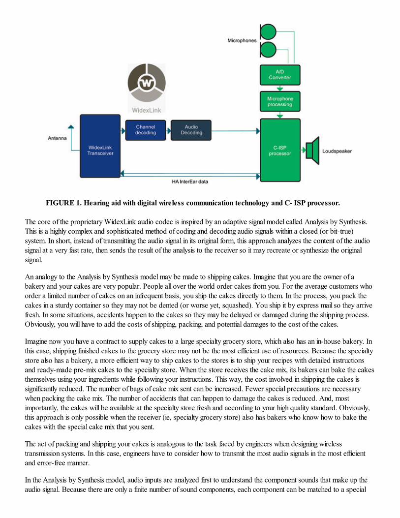
FIGURE 1. Hearing aid with digital wireless communication technology and C- ISP processor.
The core of the proprietary WidexLink audio codec is inspired by an adaptive signal model called Analysis by Synthesis.
This is a highly complex and sophisticated method of coding and decoding audio signals within a closed (or bit-true)
system. In short, instead of transmitting the audio signal in its original form, this approach analyzes the content of the audio
signal at a very fast rate, then sends the result of the analysis to the receiver so it may recreate or synthesize the original
signal.
An analogy to the Analysis by Synthesis model may be made to shipping cakes. Imagine that you are the owner of a
bakery and your cakes are very popular. People all over the world order cakes from you. For the average customers who
order a limited number of cakes on an infrequent basis, you ship the cakes directly to them. In the process, you pack the
cakes in a sturdy container so they may not be dented (or worse yet, squashed). You ship it by express mail so they arrive
fresh. In some situations, accidents happen to the cakes so they may be delayed or damaged during the shipping process.
Obviously, you will have to add the costs of shipping, packing, and potential damages to the cost of the cakes.
Imagine now you have a contract to supply cakes to a large specialty grocery store, which also has an in-house bakery. In
this case, shipping finished cakes to the grocery store may not be the most efficient use of resources. Because the specialty
store also has a bakery, a more efficient way to ship cakes to the stores is to ship your recipes with detailed instructions
and ready-made pre-mix cakes to the specialty store. When the store receives the cake mix, its bakers can bake the cakes
themselves using your ingredients while following your instructions. This way, the cost involved in shipping the cakes is
significantly reduced. The number of bags of cake mix sent can be increased. Fewer special precautions are necessary
when packing the cake mix. The number of accidents that can happen to damage the cakes is reduced. And, most
importantly, the cakes will be available at the specialty store fresh and according to your high quality standard. Obviously,
this approach is only possible when the receiver (ie, specialty grocery store) also has bakers who know how to bake the
cakes with the special cake mix that you sent.
The act of packing and shipping your cakes is analogous to the task faced by engineers when designing wireless
transmission systems. In this case, engineers have to consider how to transmit the most audio signals in the most efficient
and error-free manner.
In the Analysis by Synthesis model, audio inputs are analyzed first to understand the component sounds that make up the
audio signal. Because there are only a finite number of sound components, each component can be matched to a special
code. This code, rather than the actual sound or sound components, is transmitted wirelessly. Because both the transmitter
and the receiver (transceiver) are designed by Widex, the special code that is received can be easily translated into the
appropriate sound components. Afterward, the sound components are synthesized to recover the original audio signal. This
is only possible for a bit-true system used in the WidexLink.
There are several important benefits from using this approach. First, it dramatically reduces the number of transmitted bits
and saves on the current consumption. Second, the same number of bits carried by the system will have more details or
information of the audio data than the same number of bits carried by another codec that uses a simpler method of coding
and decoding. And third, since only the special codes are transmitted, its interception by an unintended receiver will not be
meaningful because it cannot be decoded back. Thus, data security is enhanced. Kuk et al1 described some simpler
methods of codec in the primer paper.
In WidexLink, the transmitted signals are sampled at 25 kHz to result in a realizable transmission bandwidth from 100 Hz
to 11.2 kHz—which is even broader than the broad bandwidth (10 kHz) of the CLEAR440 ClearBand model (CL4-m-
CB) when it is in the typical mode of operation (ie, microphone mode).
As is common in digitization, audio codec introduces quantization noise at the output. In many codec, the level of the noise
is independent of the level of the signal (ie, it is fixed). As a result, the signal-to-noise ratio (SNR) decreases when signal
level decreases. In the WidexLink codec, the quantization noise level adapts to the level of the input signal. As the signal
level decreases, the quantization noise decreases in order to maintain a fixed SNR. This SNR level is set to be inaudible to
the user, while still allowing for a significant amount of digital audio compression.
Channel coding. In designing the WidexLink, special attention has been paid to ensure a robust system that can
tolerate electromagnetic interference during transmission. When interference occurs, the content of the transmitted signals
may change. The difference between the "intended-for-transmission" signals and the transmitted signals is called an error.
Channel-coding algorithms provide a method to ensure and check the accuracy of the received data. They also include
additional codes that specify how errors are handled, and these error correction codes are different among manufacturers.
The codes can range from simply identifying an error to those that can anticipate the errors and correct for them—an
approach called Forward Error Correction (FEC).
The error correction method in the WidexLink is a FEC type that is capable of anticipating what types of errors will likely
occur. As a consequence, a high proportion of the transmitted 212 kbits are designated for error correction purposes so
when errors occur, they are corrected immediately. As a result, audio information is continuously passed to the user to
ensure minimum drop-out of sounds and that the transmitted sounds are of good quality. This differs from simpler digital
audio transmission systems where corrupted audio samples are either removed (resulting in a complete drop-out of the
audio) or the data are re-transmitted (which delay the transmission). The error correction codes in the WidexLink are one
of the many lines of defense in ensuring exceptional sound quality and robustness of the wireless communication system.
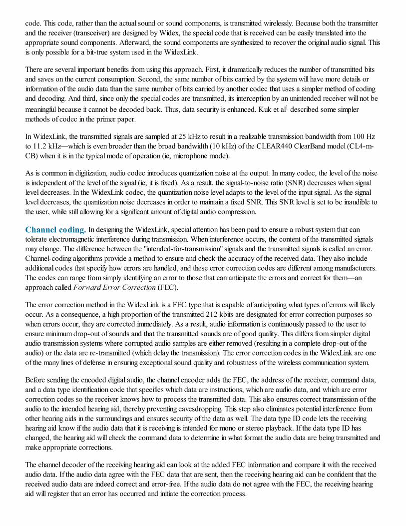
Before sending the encoded digital audio, the channel encoder adds the FEC, the address of the receiver, command data,
and a data type identification code that specifies which data are instructions, which are audio data, and which are error
correction codes so the receiver knows how to process the transmitted data. This also ensures correct transmission of the
audio to the intended hearing aid, thereby preventing eavesdropping. This step also eliminates potential interference from
other hearing aids in the surroundings and ensures security of the data as well. The data type ID code lets the receiving
hearing aid know if the audio data that it is receiving is intended for mono or stereo playback. If the data type ID has
changed, the hearing aid will check the command data to determine in what format the audio data are being transmitted and
make appropriate corrections.
The channel decoder of the receiving hearing aid can look at the added FEC information and compare it with the received
audio data. If the audio data agree with the FEC data that are sent, then the receiving hearing aid can be confident that the
received audio data are indeed correct and error-free. If the audio data do not agree with the FEC, the receiving hearing
aid will register that an error has occurred and initiate the correction process.
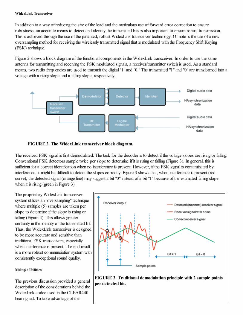
FIGURE 3. Traditional demodulation principle with 2 sample points
per detected bit.
WidexLink Transceiver
In addition to a way of reducing the size of the load and the meticulous use of forward error correction to ensure
robustness, an accurate means to detect and identify the transmitted bits is also important to ensure robust transmission.
This is achieved through the use of the patented, robust WidexLink transceiver technology. Of note is the use of a new
oversampling method for receiving the wirelessly transmitted signal that is modulated with the Frequency Shift Keying
(FSK) technique.
Figure 2 shows a block diagram of the functional components in the WidexLink transceiver. In order to use the same
antenna for transmitting and receiving the FSK modulated signals, a receiver/transmitter switch is used. As a standard
means, two radio frequencies are used to transmit the digital "1" and "0." The transmitted "1" and "0" are transformed into a
voltage with a rising slope and a falling slope, respectively.
FIGURE 2. The WidexLink transceiver block diagram.
The received FSK signal is first demodulated. The task for the decoder is to detect if the voltage slopes are rising or falling.
Conventional FSK detectors sample twice per slope to determine if it is rising or falling (Figure 3). In general, this is
sufficient for a correct identification when no interference is present. However, if the FSK signal is contaminated by
interference, it might be difficult to detect the slopes correctly. Figure 3 shows that, when interference is present (red
curve), the detected signal (orange line) may suggest a bit "0" instead of a bit "1" because of the estimated falling slope
when it is rising (green in Figure 3).
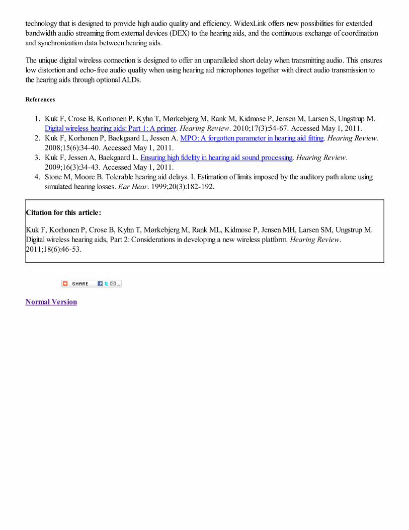
The proprietary WidexLink transceiver
system utilizes an "oversampling" technique
where multiple (5) samples are taken per
slope to determine if the slope is rising or
falling (Figure 4). This allows greater
certainty in the identity of the transmitted bit.
Thus, the WidexLink transceiver is designed
to be more accurate and sensitive than
traditional FSK transceivers, especially
when interference is present. The end result
is a more robust communciation system with
consistently exceptional sound quality.
Multiple Utilities
The previous discussion provided a general
description of the considerations behind the
WidexLink codec used in the CLEAR440
hearing aid. To take advantage of the
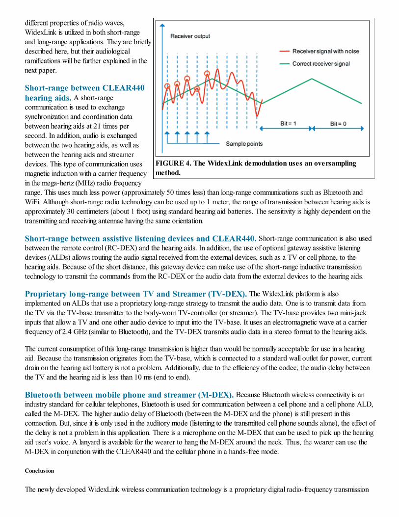
FIGURE 4. The WidexLink demodulation uses an oversampling
method.
different properties of radio waves,
WidexLink is utilized in both short-range
and long-range applications. They are briefly
described here, but their audiological
ramifications will be further explained in the
next paper.
Short-range between CLEAR440
hearing aids. A short-rangecommunication is used to exchange
synchronization and coordination data
between hearing aids at 21 times per
second. In addition, audio is exchanged
between the two hearing aids, as well as
between the hearing aids and streamer
devices. This type of communication uses
magnetic induction with a carrier frequency
in the mega-hertz (MHz) radio frequency
range. This uses much less power (approximately 50 times less) than long-range communications such as Bluetooth and
WiFi. Although short-range radio technology can be used up to 1 meter, the range of transmission between hearing aids is
approximately 30 centimeters (about 1 foot) using standard hearing aid batteries. The sensitivity is highly dependent on the
transmitting and receiving antennae having the same orientation.
Short-range between assistive listening devices and CLEAR440. Short-range communication is also usedbetween the remote control (RC-DEX) and the hearing aids. In addition, the use of optional gateway assistive listening
devices (ALDs) allows routing the audio signal received from the external devices, such as a TV or cell phone, to the
hearing aids. Because of the short distance, this gateway device can make use of the short-range inductive transmission
technology to transmit the commands from the RC-DEX or the audio data from the external devices to the hearing aids.
Proprietary long-range between TV and Streamer (TV-DEX). The WidexLink platform is also
implemented on ALDs that use a proprietary long-range strategy to transmit the audio data. One is to transmit data from
the TV via the TV-base transmitter to the body-worn TV-controller (or streamer). The TV-base provides two mini-jack
inputs that allow a TV and one other audio device to input into the TV-base. It uses an electromagnetic wave at a carrier
frequency of 2.4 GHz (similar to Bluetooth), and the TV-DEX transmits audio data in a stereo format to the hearing aids.
The current consumption of this long-range transmission is higher than would be normally acceptable for use in a hearing
aid. Because the transmission originates from the TV-base, which is connected to a standard wall outlet for power, current
drain on the hearing aid battery is not a problem. Additionally, due to the efficiency of the codec, the audio delay between
the TV and the hearing aid is less than 10 ms (end to end).
Bluetooth between mobile phone and streamer (M-DEX). Because Bluetooth wireless connectivity is anindustry standard for cellular telephones, Bluetooth is used for communication between a cell phone and a cell phone ALD,
called the M-DEX. The higher audio delay of Bluetooth (between the M-DEX and the phone) is still present in this
connection. But, since it is only used in the auditory mode (listening to the transmitted cell phone sounds alone), the effect of
the delay is not a problem in this application. There is a microphone on the M-DEX that can be used to pick up the hearing
aid user's voice. A lanyard is available for the wearer to hang the M-DEX around the neck. Thus, the wearer can use the
M-DEX in conjunction with the CLEAR440 and the cellular phone in a hands-free mode.
Conclusion
The newly developed WidexLink wireless communication technology is a proprietary digital radio-frequency transmission
technology that is designed to provide high audio quality and efficiency. WidexLink offers new possibilities for extended
bandwidth audio streaming from external devices (DEX) to the hearing aids, and the continuous exchange of coordination
and synchronization data between hearing aids.
The unique digital wireless connection is designed to offer an unparalleled short delay when transmitting audio. This ensures
low distortion and echo-free audio quality when using hearing aid microphones together with direct audio transmission to
the hearing aids through optional ALDs.
References
1. Kuk F, Crose B, Korhonen P, Kyhn T, Mørkebjerg M, Rank M, Kidmose P, Jensen M, Larsen S, Ungstrup M.
Digital wireless hearing aids: Part 1: A primer. Hearing Review. 2010;17(3):54-67. Accessed May 1, 2011.
2. Kuk F, Korhonen P, Baekgaard L, Jessen A. MPO: A forgotten parameter in hearing aid fitting. Hearing Review.
2008;15(6):34-40. Accessed May 1, 2011.
3. Kuk F, Jessen A, Baekgaard L. Ensuring high fidelity in hearing aid sound processing. Hearing Review.
2009;16(3):34-43. Accessed May 1, 2011.
4. Stone M, Moore B. Tolerable hearing aid delays. I. Estimation of limits imposed by the auditory path alone using
simulated hearing losses. Ear Hear. 1999;20(3):182-192.
Citation for this article:
Kuk F, Korhonen P, Crose B, Kyhn T, Mørkebjerg M, Rank ML, Kidmose P, Jensen MH, Larsen SM, Ungstrup M.
Digital wireless hearing aids, Part 2: Considerations in developing a new wireless platform. Hearing Review.
2011;18(6):46-53.
Normal Version
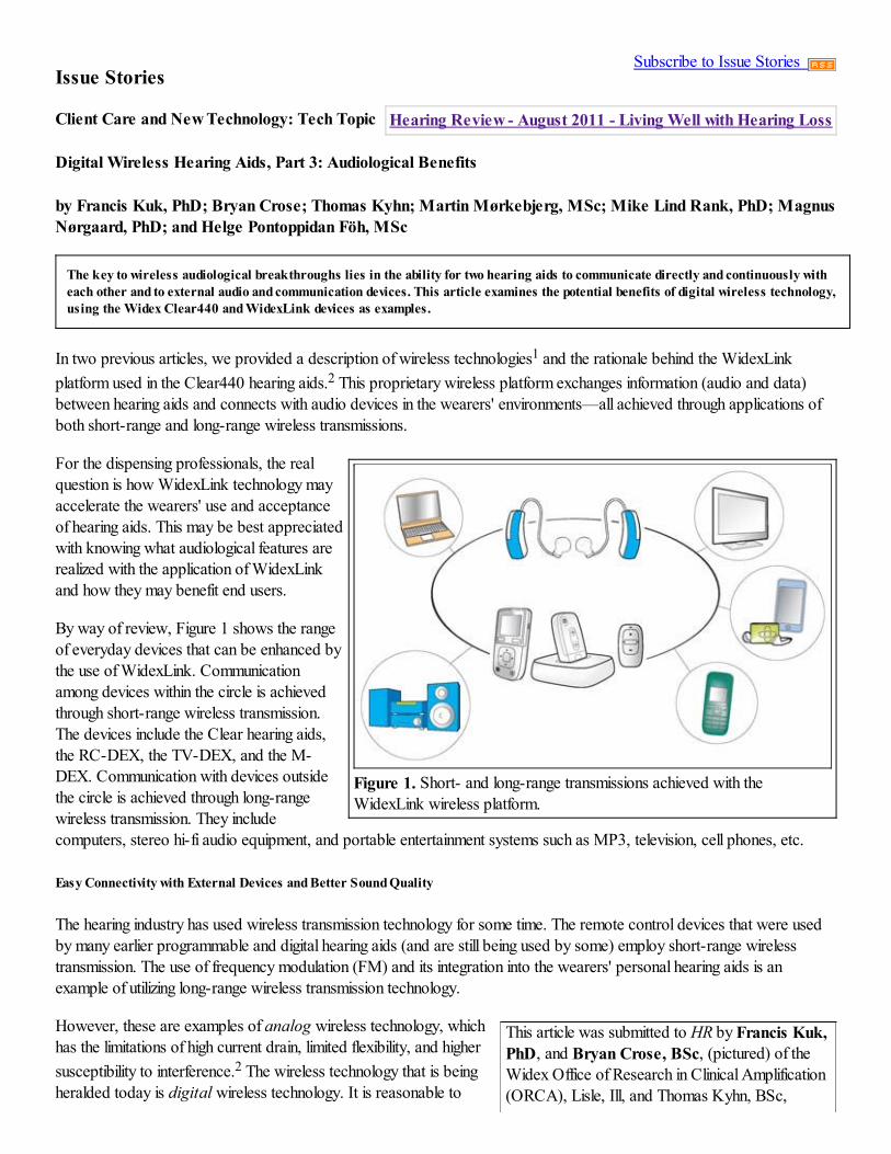
Figure 1. Short- and long-range transmissions achieved with the
WidexLink wireless platform.
This article was submitted to HR by Francis Kuk,
PhD, and Bryan Crose, BSc, (pictured) of the
Widex Office of Research in Clinical Amplification
(ORCA), Lisle, Ill, and Thomas Kyhn, BSc,
Subscribe to Issue Stories
Hearing Review - August 2011 - Living Well with Hearing Loss
Issue Stories
Client Care and New Technology: Tech Topic
Digital Wireless Hearing Aids, Part 3: Audiological Benefits
by Francis Kuk, PhD; Bryan Crose; Thomas Kyhn; Martin Mørkebjerg, MSc; Mike Lind Rank, PhD; Magnus
Nørgaard, PhD; and Helge Pontoppidan Föh, MSc
The key to wireless audiological breakthroughs lies in the ability for two hearing aids to communicate directly and continuously with
each other and to external audio and communication devices. This article examines the potential benefits of digital wireless technology,
using the Widex Clear440 and WidexLink devices as examples.
In two previous articles, we provided a description of wireless technologies1 and the rationale behind the WidexLink
platform used in the Clear440 hearing aids.2 This proprietary wireless platform exchanges information (audio and data)
between hearing aids and connects with audio devices in the wearers' environments—all achieved through applications of
both short-range and long-range wireless transmissions.
For the dispensing professionals, the real
question is how WidexLink technology may
accelerate the wearers' use and acceptance
of hearing aids. This may be best appreciated
with knowing what audiological features are
realized with the application of WidexLink
and how they may benefit end users.
By way of review, Figure 1 shows the range
of everyday devices that can be enhanced by
the use of WidexLink. Communication
among devices within the circle is achieved
through short-range wireless transmission.
The devices include the Clear hearing aids,
the RC-DEX, the TV-DEX, and the M-
DEX. Communication with devices outside
the circle is achieved through long-range
wireless transmission. They include
computers, stereo hi-fi audio equipment, and portable entertainment systems such as MP3, television, cell phones, etc.
Easy Connectivity with External Devices and Better Sound Quality
The hearing industry has used wireless transmission technology for some time. The remote control devices that were used
by many earlier programmable and digital hearing aids (and are still being used by some) employ short-range wireless
transmission. The use of frequency modulation (FM) and its integration into the wearers' personal hearing aids is an
example of utilizing long-range wireless transmission technology.
However, these are examples of analog wireless technology, which
has the limitations of high current drain, limited flexibility, and higher
susceptibility to interference.2 The wireless technology that is being
heralded today is digital wireless technology. It is reasonable to
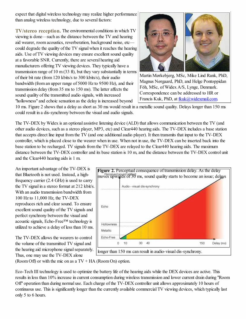
Martin Mørkebjerg, MSc, Mike Lind Rank, PhD,
Magnus Nørgaard, PhD, and Helge Pontoppidan
Föh, MSc, of Widex A/S, Lynge, Denmark.
Correspondence can be addressed to HR or
Francis Kuk, PhD, at [email protected].
Figure 2. Perceptual consequence of transmission delay. As the delay
moves upwards of 30 ms, sound quality starts to become an issue; delays
longer than 150 ms can result in audio-visual dis-synchrony.
expect that digital wireless technology may realize higher performance
than analog wireless technology, due to several factors:
TV/stereo reception. The environmental conditions in which TV
viewing is done—such as the distance between the TV and hearing
aid wearer, room acoustics, reverberation, background noise, etc—
could degrade the quality of the TV signal when it reaches the hearing
aids. Use of TV viewing devices may ensure excellent sound quality
at a favorable SNR. Currently, there are several hearing aid
manufacturers offering TV viewing devices. They typically have a
transmission range of 10 m (33 ft), but they vary substantially in terms
of their bit rate (from 120 kbits/s to 300 kbits/s), their audio
bandwidth (from an upper range of 5000 Hz to 9500 Hz), and their
transmission delay (from 35 ms to 150 ms). The latter affects the
sound quality of the transmitted audio signals, with increased
"hollowness" and echoic sensation as the delay is increased beyond
10 ms. Figure 2 shows that a delay as short as 30 ms would result in a metallic sound quality. Delays longer than 150 ms
could result in a dis-synchrony between the visual and audio signals.
The TV-DEX by Widex is an optional assistive listening device (ALD) that allows communication between the TV (and
other audio devices, such as a stereo player, MP3, etc) and Clear440 hearing aids. The TV-DEX includes a base station
that accepts direct line input from the TV (and one additional audio player). It then transmits that input to the TV-DEX
controller, which is placed close to the wearer when in use. When not in use, the TV-DEX can be inserted back into the
base station to be recharged. TV signals from the TV-DEX are relayed to the Clear440 hearing aids. The maximum
distance between the TV-DEX controller and its base station is 10 m, and the distance between the TV-DEX control unit
and the Clear440 hearing aids is 1 m.
An important advantage of the TV-DEX is
that Bluetooth is not used. Instead, a high-
frequency carrier (2.4 GHz) is used to carry
the TV signal in a stereo format at 212 kbit/s.
With an audio transmission bandwidth from
100 Hz to 11,000 Hz, the TV-DEX
reproduces rich and clear sound. To ensure
excellent sound quality of the TV signals and
perfect synchrony between the visual and
acoustic signals, Echo-Free™ technology is
utilized to achieve a delay of less than 10 ms.
The TV-DEX allows the wearers to control
the volume of the transmitted TV signal and
the hearing aid microphone signal separately.
Thus, one may use the TV-DEX alone
(Room Off) or with the mic on as a TV + HA (Room On) option.
Eco-Tech III technology is used to optimize the battery life of the hearing aids while the DEX devices are active. This
results in less than 10% increase in current consumption during wireless transmission and lower current drain during "Room
Off" operation than during normal use. Each charge of the TV-DEX controller unit allows approximately 10 hours of
continuous use. This is significantly longer than the currently available commercial TV viewing devices, which typically last
only 5 to 6 hours.
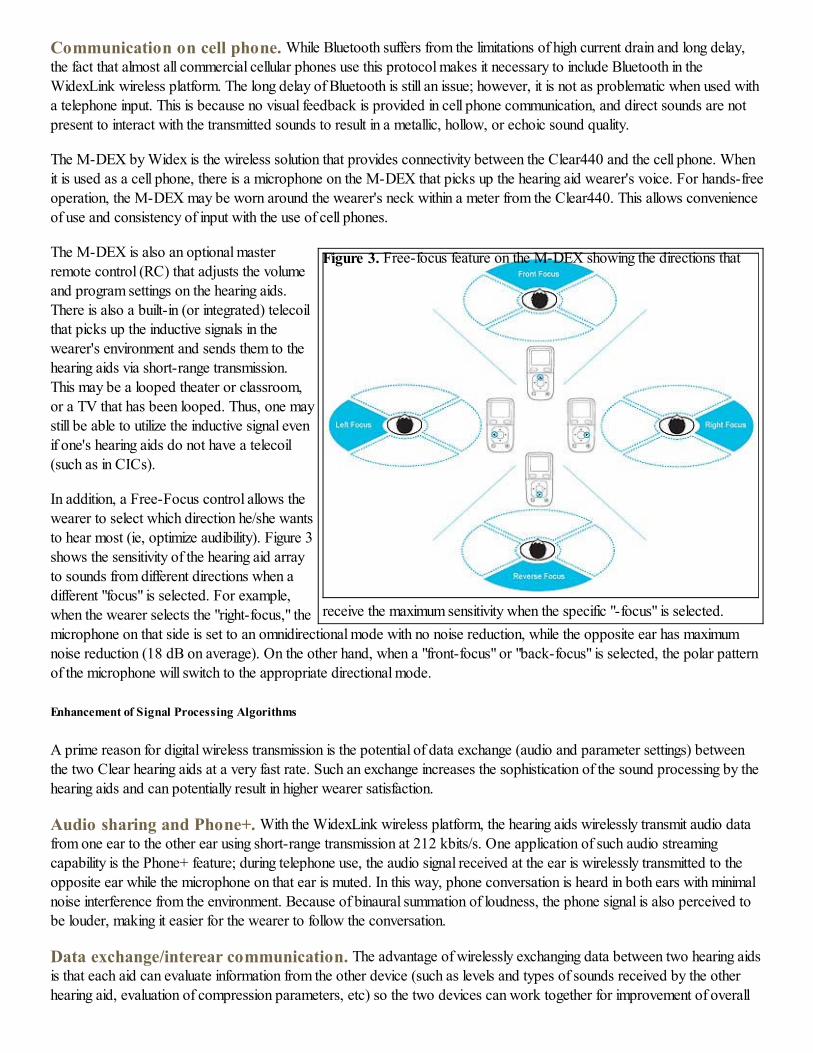
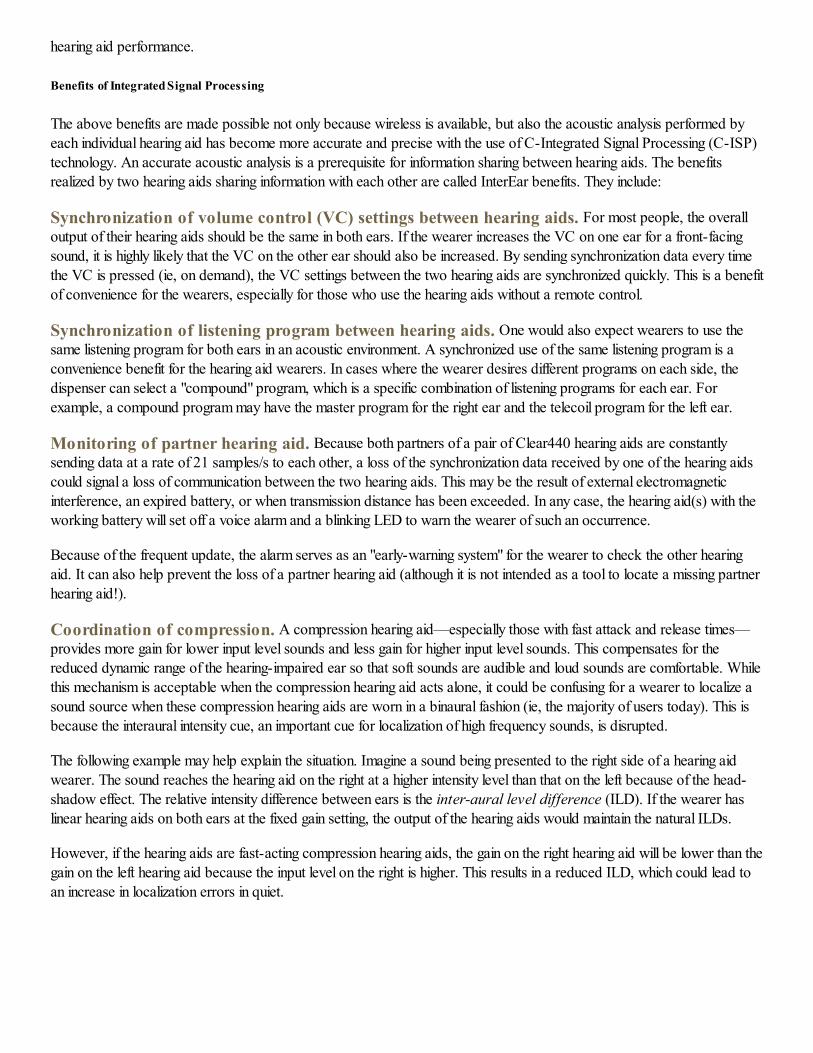
Figure 3. Free-focus feature on the M-DEX showing the directions that
receive the maximum sensitivity when the specific "-focus" is selected.
Communication on cell phone. While Bluetooth suffers from the limitations of high current drain and long delay,
the fact that almost all commercial cellular phones use this protocol makes it necessary to include Bluetooth in the
WidexLink wireless platform. The long delay of Bluetooth is still an issue; however, it is not as problematic when used with
a telephone input. This is because no visual feedback is provided in cell phone communication, and direct sounds are not
present to interact with the transmitted sounds to result in a metallic, hollow, or echoic sound quality.
The M-DEX by Widex is the wireless solution that provides connectivity between the Clear440 and the cell phone. When
it is used as a cell phone, there is a microphone on the M-DEX that picks up the hearing aid wearer's voice. For hands-free
operation, the M-DEX may be worn around the wearer's neck within a meter from the Clear440. This allows convenience
of use and consistency of input with the use of cell phones.
The M-DEX is also an optional master
remote control (RC) that adjusts the volume
and program settings on the hearing aids.
There is also a built-in (or integrated) telecoil
that picks up the inductive signals in the
wearer's environment and sends them to the
hearing aids via short-range transmission.
This may be a looped theater or classroom,
or a TV that has been looped. Thus, one may
still be able to utilize the inductive signal even
if one's hearing aids do not have a telecoil
(such as in CICs).
In addition, a Free-Focus control allows the
wearer to select which direction he/she wants
to hear most (ie, optimize audibility). Figure 3
shows the sensitivity of the hearing aid array
to sounds from different directions when a
different "focus" is selected. For example,
when the wearer selects the "right-focus," the
microphone on that side is set to an omnidirectional mode with no noise reduction, while the opposite ear has maximum
noise reduction (18 dB on average). On the other hand, when a "front-focus" or "back-focus" is selected, the polar pattern
of the microphone will switch to the appropriate directional mode.
Enhancement of Signal Processing Algorithms
A prime reason for digital wireless transmission is the potential of data exchange (audio and parameter settings) between
the two Clear hearing aids at a very fast rate. Such an exchange increases the sophistication of the sound processing by the
hearing aids and can potentially result in higher wearer satisfaction.
Audio sharing and Phone+. With the WidexLink wireless platform, the hearing aids wirelessly transmit audio data
from one ear to the other ear using short-range transmission at 212 kbits/s. One application of such audio streaming
capability is the Phone+ feature; during telephone use, the audio signal received at the ear is wirelessly transmitted to the
opposite ear while the microphone on that ear is muted. In this way, phone conversation is heard in both ears with minimal
noise interference from the environment. Because of binaural summation of loudness, the phone signal is also perceived to
be louder, making it easier for the wearer to follow the conversation.
Data exchange/interear communication. The advantage of wirelessly exchanging data between two hearing aids
is that each aid can evaluate information from the other device (such as levels and types of sounds received by the other
hearing aid, evaluation of compression parameters, etc) so the two devices can work together for improvement of overall
hearing aid performance.
Benefits of Integrated Signal Processing
The above benefits are made possible not only because wireless is available, but also the acoustic analysis performed by
each individual hearing aid has become more accurate and precise with the use of C-Integrated Signal Processing (C-ISP)
technology. An accurate acoustic analysis is a prerequisite for information sharing between hearing aids. The benefits
realized by two hearing aids sharing information with each other are called InterEar benefits. They include:
Synchronization of volume control (VC) settings between hearing aids. For most people, the overall
output of their hearing aids should be the same in both ears. If the wearer increases the VC on one ear for a front-facing
sound, it is highly likely that the VC on the other ear should also be increased. By sending synchronization data every time
the VC is pressed (ie, on demand), the VC settings between the two hearing aids are synchronized quickly. This is a benefit
of convenience for the wearers, especially for those who use the hearing aids without a remote control.
Synchronization of listening program between hearing aids. One would also expect wearers to use the
same listening program for both ears in an acoustic environment. A synchronized use of the same listening program is a
convenience benefit for the hearing aid wearers. In cases where the wearer desires different programs on each side, the
dispenser can select a "compound" program, which is a specific combination of listening programs for each ear. For
example, a compound program may have the master program for the right ear and the telecoil program for the left ear.
Monitoring of partner hearing aid. Because both partners of a pair of Clear440 hearing aids are constantly
sending data at a rate of 21 samples/s to each other, a loss of the synchronization data received by one of the hearing aids
could signal a loss of communication between the two hearing aids. This may be the result of external electromagnetic
interference, an expired battery, or when transmission distance has been exceeded. In any case, the hearing aid(s) with the
working battery will set off a voice alarm and a blinking LED to warn the wearer of such an occurrence.
Because of the frequent update, the alarm serves as an "early-warning system" for the wearer to check the other hearing
aid. It can also help prevent the loss of a partner hearing aid (although it is not intended as a tool to locate a missing partner
hearing aid!).
Coordination of compression. A compression hearing aid—especially those with fast attack and release times—
provides more gain for lower input level sounds and less gain for higher input level sounds. This compensates for the
reduced dynamic range of the hearing-impaired ear so that soft sounds are audible and loud sounds are comfortable. While
this mechanism is acceptable when the compression hearing aid acts alone, it could be confusing for a wearer to localize a
sound source when these compression hearing aids are worn in a binaural fashion (ie, the majority of users today). This is
because the interaural intensity cue, an important cue for localization of high frequency sounds, is disrupted.
The following example may help explain the situation. Imagine a sound being presented to the right side of a hearing aid
wearer. The sound reaches the hearing aid on the right at a higher intensity level than that on the left because of the head-
shadow effect. The relative intensity difference between ears is the inter-aural level difference (ILD). If the wearer has
linear hearing aids on both ears at the fixed gain setting, the output of the hearing aids would maintain the natural ILDs.
However, if the hearing aids are fast-acting compression hearing aids, the gain on the right hearing aid will be lower than the
gain on the left hearing aid because the input level on the right is higher. This results in a reduced ILD, which could lead to
an increase in localization errors in quiet.
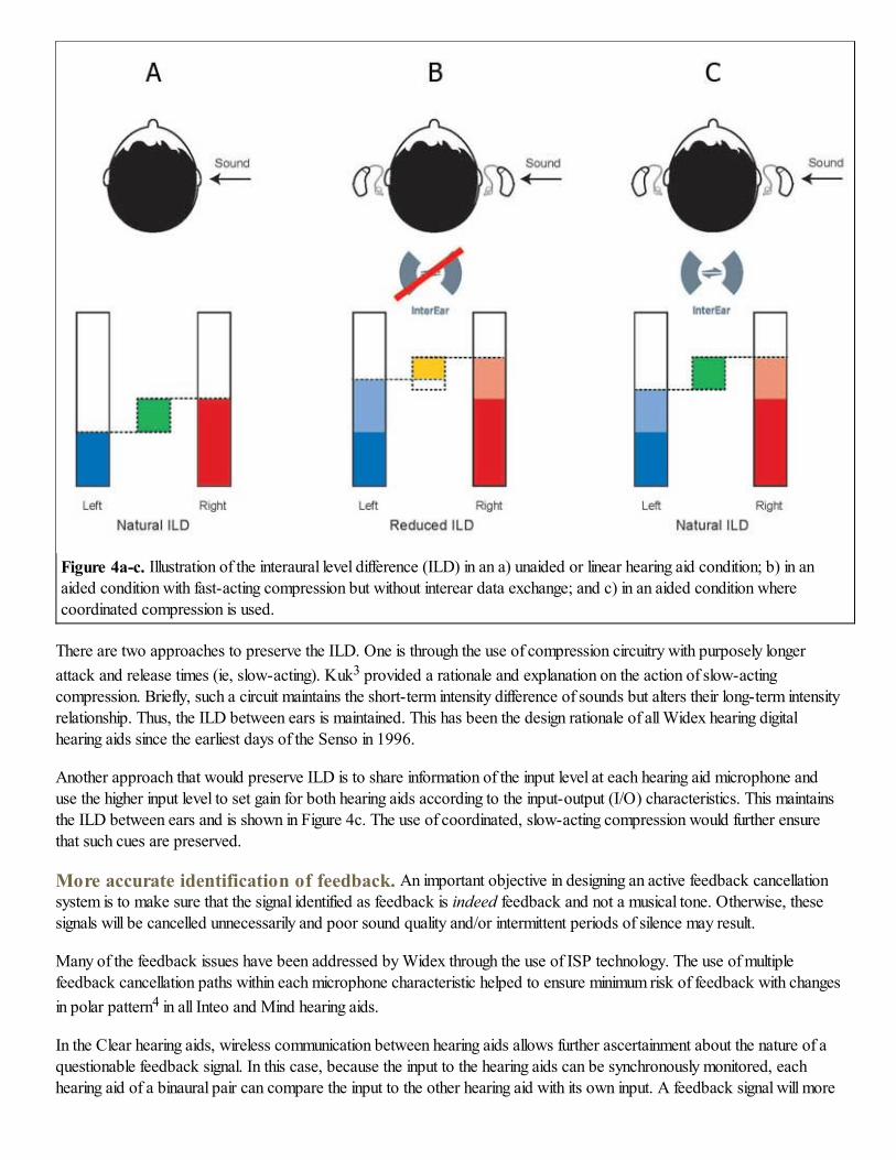
Figure 4a-c. Illustration of the interaural level difference (ILD) in an a) unaided or linear hearing aid condition; b) in an
aided condition with fast-acting compression but without interear data exchange; and c) in an aided condition where
coordinated compression is used.
There are two approaches to preserve the ILD. One is through the use of compression circuitry with purposely longer
attack and release times (ie, slow-acting). Kuk3 provided a rationale and explanation on the action of slow-acting
compression. Briefly, such a circuit maintains the short-term intensity difference of sounds but alters their long-term intensity
relationship. Thus, the ILD between ears is maintained. This has been the design rationale of all Widex hearing digital
hearing aids since the earliest days of the Senso in 1996.
Another approach that would preserve ILD is to share information of the input level at each hearing aid microphone and
use the higher input level to set gain for both hearing aids according to the input-output (I/O) characteristics. This maintains
the ILD between ears and is shown in Figure 4c. The use of coordinated, slow-acting compression would further ensure
that such cues are preserved.
More accurate identification of feedback. An important objective in designing an active feedback cancellation
system is to make sure that the signal identified as feedback is indeed feedback and not a musical tone. Otherwise, these
signals will be cancelled unnecessarily and poor sound quality and/or intermittent periods of silence may result.
Many of the feedback issues have been addressed by Widex through the use of ISP technology. The use of multiple
feedback cancellation paths within each microphone characteristic helped to ensure minimum risk of feedback with changes
in polar pattern4 in all Inteo and Mind hearing aids.
In the Clear hearing aids, wireless communication between hearing aids allows further ascertainment about the nature of a
questionable feedback signal. In this case, because the input to the hearing aids can be synchronously monitored, each
hearing aid of a binaural pair can compare the input to the other hearing aid with its own input. A feedback signal will more
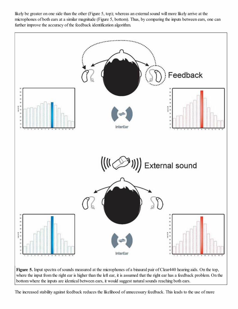
likely be greater on one side than the other (Figure 5, top); whereas an external sound will more likely arrive at the
microphones of both ears at a similar magnitude (Figure 5, bottom). Thus, by comparing the inputs between ears, one can
further improve the accuracy of the feedback identification algorithm.
Figure 5. Input spectra of sounds measured at the microphones of a binaural pair of Clear440 hearing aids. On the top,
where the input from the right ear is higher than the left ear, it is assumed that the right ear has a feedback problem. On the
bottom where the inputs are identical between ears, it would suggest natural sounds reaching both ears.
The increased stability against feedback reduces the likelihood of unnecessary feedback. This leads to the use of more
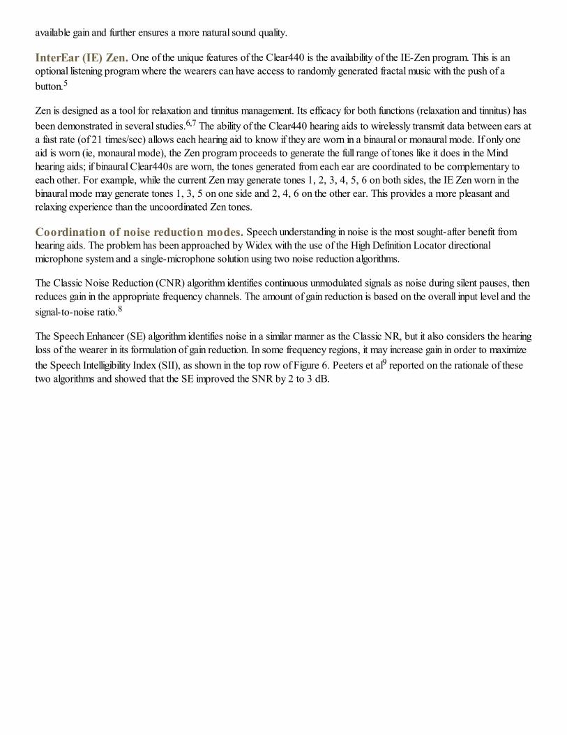
available gain and further ensures a more natural sound quality.
InterEar (IE) Zen. One of the unique features of the Clear440 is the availability of the IE-Zen program. This is an
optional listening program where the wearers can have access to randomly generated fractal music with the push of a
button.5
Zen is designed as a tool for relaxation and tinnitus management. Its efficacy for both functions (relaxation and tinnitus) has
been demonstrated in several studies.6,7 The ability of the Clear440 hearing aids to wirelessly transmit data between ears at
a fast rate (of 21 times/sec) allows each hearing aid to know if they are worn in a binaural or monaural mode. If only one
aid is worn (ie, monaural mode), the Zen program proceeds to generate the full range of tones like it does in the Mind
hearing aids; if binaural Clear440s are worn, the tones generated from each ear are coordinated to be complementary to
each other. For example, while the current Zen may generate tones 1, 2, 3, 4, 5, 6 on both sides, the IE Zen worn in the
binaural mode may generate tones 1, 3, 5 on one side and 2, 4, 6 on the other ear. This provides a more pleasant and
relaxing experience than the uncoordinated Zen tones.
Coordination of noise reduction modes. Speech understanding in noise is the most sought-after benefit from
hearing aids. The problem has been approached by Widex with the use of the High Definition Locator directional
microphone system and a single-microphone solution using two noise reduction algorithms.
The Classic Noise Reduction (CNR) algorithm identifies continuous unmodulated signals as noise during silent pauses, then
reduces gain in the appropriate frequency channels. The amount of gain reduction is based on the overall input level and the
signal-to-noise ratio.8
The Speech Enhancer (SE) algorithm identifies noise in a similar manner as the Classic NR, but it also considers the hearing
loss of the wearer in its formulation of gain reduction. In some frequency regions, it may increase gain in order to maximize
the Speech Intelligibility Index (SII), as shown in the top row of Figure 6. Peeters et al9 reported on the rationale of these
two algorithms and showed that the SE improved the SNR by 2 to 3 dB.
Figure 6. Illustration on the mechanism of the IE-speech enhancer. When IE is activated, speech
detected on the dominant side will maintain maximum speech intelligibility index (SII) with gain
increase, while the other side will reduce gain for the noise and not increase gain for speech on that
side.
The IE-speech enhancer (IE-SE) noise management program brings noise reduction to a higher level of sophistication. By
sharing the results of the acoustic analyses conducted between ears wirelessly, each hearing aid decides if it has a dominant
speech input or dominant noise content. Once that decision is made, the side with the dominant speech will be set to the SE
noise reduction to optimize the SII through appropriate gain reduction AND gain increase. The side with the dominant
noise will be set for SE but with gain reduction only. In essence, it raises the level of the speech input on one side and
reduces the level of the noise input on the opposite side (Figure 6, bottom).
Convenient Programming
Almost all modern hearing aids are programmed with computers. Not too long ago, hearing aids had to be physically
connected to an interface called the Hi-Pro box, which in turn was connected to the computer via cables. This tied the
clinicians and the wearers to the computer during programming. It also required manufacturer-specific and model-specific
programming cables.
The application of Bluetooth in the wireless Noahlink programmer is a major step forward. It brings flexibility and speed to
hearing aid programming. The Noahlink is wirelessly connected to the computer via Bluetooth, and the hearing aids are
physically connected (via cables) to the portable Noahlink. This arrangement provides tremendous flexibility and efficiency
to the programming over the wired interface Hi-Pro box. Tasks such as paired comparison of program settings, real-time
display of input to the hearing aids,10 and increased speed of programming are possible. It also frees the wearers from
being "tied" to the programming station, allowing movement of the wearer into different acoustic environments during
programming. A practical advantage is that clinicians can perform hearing aid programming outside a booth while patients
sit inside the booth.11
Despite the wireless nature of Bluetooth, the wearers' hearing aids are still physically connected to the Noahlink via
connecting cables. Different programming cables are needed for different manufacturers and for their various models. On
the other hand, one can replace the cable functions by integrating short-range wireless transmission within the current
Noahlink Bluetooth. A new programming device, the nEarCom, is a "neck-hook" attachment to the current Noahlink
interface that enables data to/from the hearing aids to be transmitted wirelessly to Noahlink. The advantage of the nEarCom
is that no programming cables are needed regardless of the hearing aid styles (such as BTE vs CIC style) for the
participating manufacturers. Only a manufacturer-specific programming module needs to be inserted into the neck hook for
access. This removes one source of clutter and/or confusion in the hearing aid clinic and streamlines programming.
Conclusion
The key to wireless audiological breakthroughs lies in the ability for two hearing aids to communicate directly and
continuously with each other and to external audio and communication devices. The WidexLink digital wireless transmission
technology provides this convenient physical basis for more thorough analysis of the environment. It also provides a more
flexible and sophisticated processing that allows hearing aid wearers better control of their acoustic environments. The end
result is a richer and cleaner sound quality, which may further improve wearer satisfaction for hearing aids. In selecting a
wireless hearing aid system, it is important that clinicians are fully aware of the wireless features and how they may help
their patients. Wireless brings the world closer—clearly and conveniently.
References
1. Kuk F, Crose B, Korhonen P, Kyhn T, Mørkebjerg M, Rank M, Kidmose P, Jensen M, Larsen S, Ungstrup M.
Digital wireless hearing aids, Part 1: A primer. Hearing Review. 2010;17(3):54-67. Accessed May 1, 2011.
2. Kuk F, Korhonen P, Crose B, Kyhn T, Mørkebjerg M, Rank ML, Kidmose P, Jensen MH, Larsen SM, Ungstrup
M. Digital wireless hearing aids, Part 2: Considerations in developing a new wireless platform. Hearing Review.
2011;18(6):46-53.
3. Kuk F. Rationale and requirements for a slow acting compression hearing aid. Hear Jour. 1998;51(6):45-53,79.
4. Kuk F, Jessen A, Klingby K, Henningsen L, Peeters H, Keenan D. Changing with the times: additional criteria to
judge the effectiveness of active feedback cancellation algorithm. Hearing Review. 2006;13(10):38-48. Accessed
July 11, 2011.
5. Kuk F, Peeters H. Hearing aids as music synthesizer. Hearing Review. 2008;15(11):28-38. Accessed July 11,
2011.
6. Sweetow R, Henderson-Sabes J. Effects of acoustical stimuli delivered through hearing aids on tinnitus. J Am Acad
Audiol. 2010;21(7):461-473.
7. Kuk F, Peeters H, Lau C. The efficacy of fractal music employed in hearing aids for tinnitus management. Hearing
Review. 2010;17(10):32-42. Accessed July 11, 2011.
8. Kuk F, Ludvigsen C, Paludan-Muller C. Improving hearing aid performance in noise: challenges and strategies.
Hear Jour. 2002;55(4):34-46.
9. Peeters H, Kuk F, Lau C, Keenan D. Subjective and objective measures of noise management algorithms. J Am
Acad Audiol. 2009;20(2):89-98.
10. Kuk F, Damsgaard A, Bulow M, Ludvigsen C. Using digital hearing aids to visualize real-life effects of signal
processing. Hear Jour. 2004;57(4):40-49.
11. Ingrao B. Bluetooth technology: toward more wireless hearing care solutions. Hearing Review. 2005;12(1):26-
27,88. Accessed July 11, 2011.

0
Citation for this article:
Kuk F, Crose B, Kyhn T, Mørkebjerg M, Rank ML, Nørgaard M, Pontoppidan H. Digital Wireless Hearing Aids, Part 3:
Audiological Benefits. Hearing Review. 2011;18(8):48-56.
Normal Version