Embed Size (px)
Citation preview

Project: Kiddie Acadamy
Address: 1400 N. Vasco Rd.
Livermore, CA 94551
Job No. D031014
Revision: Delta 1 - Plan Check
Date:
Client: Ferreri & Blau
Structural Calculations For:
May 8, 2015

1 piece(s) 20" TJI® 560 @ 32" OC
• Blocking Panels are assumed to carry no loads applied directly above them and the full load is applied to the member being designed.• At hanger supports, the Total Bearing dimension is equal to the width of the material that is supporting the hanger• ¹ See Connector grid below for additional information and/or requirements.
Bearing Length Loads to Supports (lbs)
Supports Total Available Required Dead Roof Live Total Accessories
1 - Beveled Plate - DF 3.50" 3.50" 2.55" 943 900 1843 Blocking
2 - Hanger on 20" DF beam 3.50" Hanger¹ 2.80" 1049 904 1953 See note ¹
All locations are measured from the outside face of left support (or left cantilever end). All dimensions are horizontal.
Design Results Actual @ Location Allowed Result LDF Load: Combination (Pattern)
Member Reaction (lbs) 1926 @ 33' 6 1/2" 1926 (2.80") Passed (100%) 1.25 1.0 D + 1.0 Lr (All Spans) Shear (lbs) 1926 @ 33' 6 1/2" 4181 Passed (46%) 1.25 1.0 D + 1.0 Lr (All Spans) Moment (Ft-lbs) 16955 @ 16' 6" 20206 Passed (84%) 1.25 1.0 D + 1.0 Lr (All Spans) Live Load Defl. (in) 0.786 @ 16' 10 1/2" 1.667 Passed (L/509) -- 1.0 D + 1.0 Lr (All Spans) Total Load Defl. (in) 1.765 @ 17' 1/16" 2.223 Passed (L/227) -- 1.0 D + 1.0 Lr (All Spans)
System : Roof
Member Type : Joist
Building Use : Residential
Building Code : IBC
Design Methodology : ASD
Member Pitch: 0.25/12
• Deflection criteria: LL (L/240) and TL (L/180).• Bracing (Lu): All compression edges (top and bottom) must be braced at 4' 9 7/8" o/c unless detailed otherwise. Proper attachment and positioning of lateral
bracing is required to achieve member stability.
Roof, Typical Roof Joist with MechanicalMEMBER REPORT PASSED
Connector: Simpson Strong-Tie Connectors Support Model Seat Length Top Nails Face Nails Member Nails Accessories
2 - Face Mount Hanger Connector not found N/A N/A N/A N/A
Weyerhaeuser warrants that the sizing of its products will be in accordance with Weyerhaeuser product design criteria and published design values. Weyerhaeuser expressly disclaims any other warranties related to the software. Refer to current Weyerhaeuser literature for installation details. (www.woodbywy.com) Accessories (Rim Board, Blocking Panels and Squash Blocks) are not designed by this software. Use of this software is not intended to circumvent the need for a design professional as determined by the authority having jurisdiction. The designer of record, builder or framer is responsible to assure that this calculation is compatible with the overall project. Products manufactured at Weyerhaeuser facilities are third-party certified to sustainable forestry standards.
The product application, input design loads, dimensions and support information have been provided by Forte Software Operator
Weyerhaeuser Notes
Dead Roof LiveLoads Location Spacing (0.90) (non-snow: 1.25) Comments
1 - Uniform (PSF) 0 to 33' 10" 32" 16.0 20.0 Roof
2 - Point (lb) 16' 6" N/A 274 -
3 - Point (lb) 23' 6" N/A 274 -
5/12/2015 5:43:02 PMForte v4.6, Design Engine: V6.1.1.5
Page 1 of 1
Roof Joist Calcs.4te
Forte Software Operator
Justen PeekDP Advanced Engineering Inc.(925) [email protected]
Job Notes

INPUT DATA
TOTAL SHEAR FORCE (ASD) Fp = 23.727 kips
NUMBER OF SEGMENTS n = 3
Segment 1 2 3
Length, ft 14.75 39.25 13
Shear Wall ? YES NO YES
ANALYSIS
TOTAL DRAG LENGTH Ldrag = 67 ft
TOTAL SHEAR WALL LENGTH Lwall = 27.75 ft
DIAPHRAGM SHEAR STRESS vdiaphragm = Fp / vdrag = 354 plf
SHEAR WALL SHEAR STRESS vshear wall = Fp / vwall = 855 plf
Section Point 0 1 2 3
Distance, ft 0 14.75 54 67
Axial Force 0 7.39 -6.51 0.00
DRAG / COLLECTOR FORCE DIAGRAM
SHEAR WALL & DRAG ELEVATION
Drag / Collector Force Diagram Generator
-8-6-4-202468
10
Dra
g A
xia
l F
orc
e,
kip
s
Distance, ft

INPUT DATA
TOTAL SHEAR FORCE (ASD) Fp = 23.568 kips
NUMBER OF SEGMENTS n = 2
Segment 1 2
Length, ft 26.25 40
Shear Wall ? NO YES
ANALYSIS
TOTAL DRAG LENGTH Ldrag = 66.25 ft
TOTAL SHEAR WALL LENGTH Lwall = 40 ft
DIAPHRAGM SHEAR STRESS vdiaphragm = Fp / vdrag = 356 plf
SHEAR WALL SHEAR STRESS vshear wall = Fp / vwall = 589 plf
Section Point 0 1 2
Distance, ft 0 26.25 66.25
Axial Force 0 -9.34 0.00
DRAG / COLLECTOR FORCE DIAGRAM
SHEAR WALL & DRAG ELEVATION
Drag / Collector Force Diagram Generator
-10
-8
-6
-4
-2
0
2
Dra
g A
xia
l F
orc
e,
kip
s
Distance, ft
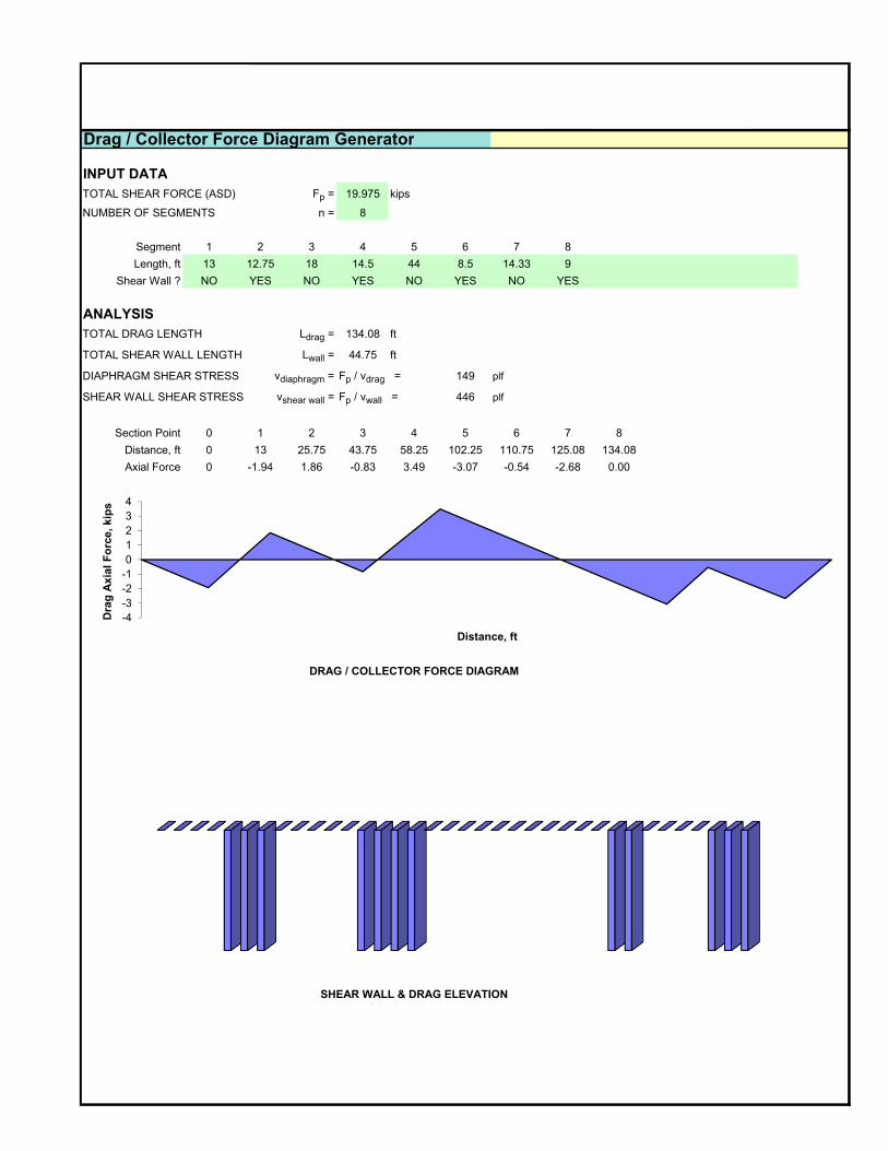
INPUT DATA
TOTAL SHEAR FORCE (ASD) Fp = 19.975 kips
NUMBER OF SEGMENTS n = 8
Segment 1 2 3 4 5 6 7 8
Length, ft 13 12.75 18 14.5 44 8.5 14.33 9
Shear Wall ? NO YES NO YES NO YES NO YES
ANALYSIS
TOTAL DRAG LENGTH Ldrag = 134.08 ft
TOTAL SHEAR WALL LENGTH Lwall = 44.75 ft
DIAPHRAGM SHEAR STRESS vdiaphragm = Fp / vdrag = 149 plf
SHEAR WALL SHEAR STRESS vshear wall = Fp / vwall = 446 plf
Section Point 0 1 2 3 4 5 6 7 8
Distance, ft 0 13 25.75 43.75 58.25 102.25 110.75 125.08 134.08
Axial Force 0 -1.94 1.86 -0.83 3.49 -3.07 -0.54 -2.68 0.00
DRAG / COLLECTOR FORCE DIAGRAM
SHEAR WALL & DRAG ELEVATION
Drag / Collector Force Diagram Generator
-4
-3
-2
-1
0
1
2
3
4
Dra
g A
xia
l F
orc
e,
kip
s
Distance, ft

INPUT DATA
TOTAL SHEAR FORCE (ASD) Fp = 23.287 kips
NUMBER OF SEGMENTS n = 3
Segment 1 2 3
Length, ft 68.67 16 49.75
Shear Wall ? NO YES NO
ANALYSIS
TOTAL DRAG LENGTH Ldrag = 134.42 ft
TOTAL SHEAR WALL LENGTH Lwall = 16 ft
DIAPHRAGM SHEAR STRESS vdiaphragm = Fp / vdrag = 173 plf
SHEAR WALL SHEAR STRESS vshear wall = Fp / vwall = 1455 plf
Section Point 0 1 2 3
Distance, ft 0 68.67 84.67 134.42
Axial Force 0 -11.90 8.62 0.00
DRAG / COLLECTOR FORCE DIAGRAM
SHEAR WALL & DRAG ELEVATION
Drag / Collector Force Diagram Generator
-15
-10
-5
0
5
10
Dra
g A
xia
l F
orc
e,
kip
s
Distance, ft

INPUT DATA
TOTAL SHEAR FORCE (ASD) Fp = 4.032 kips
NUMBER OF SEGMENTS n = 9
Segment 1 2 3 4 5 6 7 8 9
Length, ft 16 3 16 3 16 3 16 3 16
Shear Wall ? NO YES NO YES NO YES NO YES NO
ANALYSIS
TOTAL DRAG LENGTH Ldrag = 92 ft
TOTAL SHEAR WALL LENGTH Lwall = 12 ft
DIAPHRAGM SHEAR STRESS vdiaphragm = Fp / vdrag = 44 plf
SHEAR WALL SHEAR STRESS vshear wall = Fp / vwall = 336 plf
Section Point 0 1 2 3 4 5 6 7 8 9
Distance, ft 0 16 19 35 38 54 57 73 76 92
Axial Force 0 -0.70 0.18 -0.53 0.35 -0.35 0.53 -0.18 0.70 0.00
DRAG / COLLECTOR FORCE DIAGRAM
SHEAR WALL & DRAG ELEVATION
Drag / Collector Force Diagram Generator
-0.8
-0.6
-0.4
-0.2
0
0.2
0.4
0.6
0.8
Dra
g A
xia
l F
orc
e,
kip
s
Distance, ft
PROJECT: Kiddie Acadamy
CLIENT: Ferreri & Blau
JOB NO.: D031014 CALCS BY: J. Peek DATE: 5/8/2015
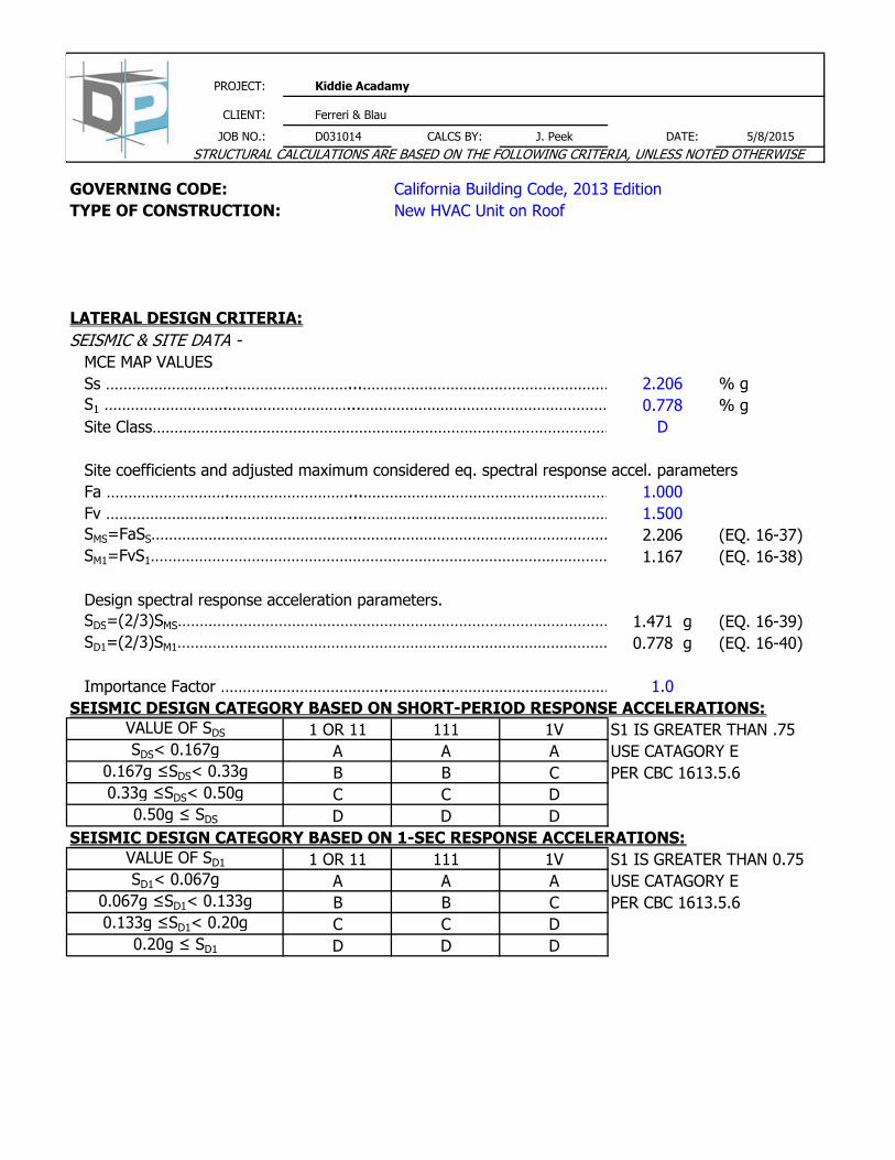
GOVERNING CODE: California Building Code, 2013 Edition
TYPE OF CONSTRUCTION: New HVAC Unit on Roof
Lateral Load System - Wood Framed Shear Walls
SEISMIC & SITE DATA -
MCE MAP VALUES
Ss ……………………….………………………...………………………………………………………………………….2.206 % g
S1 ……………………….………………………...……………………………………………………………………………………..0.778 % g
Site Class………………………………………………………………………………………………………………………….D
Site coefficients and adjusted maximum considered eq. spectral response accel. parameters
Fa ……………………….………………………...…………………………………………………………………………1.000
Fv ……………………….………………………...………………………………………………………………………..1.500
SMS=FaSS……………………………………………………………………………………………………………………………..2.206 (EQ. 16-37)
SM1=FvS1………………………………………………………………………………………………………………………………………………..1.167 (EQ. 16-38)
Design spectral response acceleration parameters.
SDS=(2/3)SMS…………………………………………………………………………………………………………………………………………………1.471 g (EQ. 16-39)
SD1=(2/3)SM1………………………………………………………………………………………………………………………………………….0.778 g (EQ. 16-40)
Importance Factor ………………………………..………….………………………………………………..1.0
SEISMIC DESIGN CATEGORY BASED ON SHORT-PERIOD RESPONSE ACCELERATIONS:
1 OR 11 111 1V S1 IS GREATER THAN .75
A A A USE CATAGORY E
B B C PER CBC 1613.5.6
C C D USE CATEGORY D
D D D USE CATEGORY D
SEISMIC DESIGN CATEGORY BASED ON 1-SEC RESPONSE ACCELERATIONS:
1 OR 11 111 1V S1 IS GREATER THAN 0.75
A A A USE CATAGORY E
B B C PER CBC 1613.5.6
C C D USE CATEGORY D
D D D USE CATEGORY D
0.067g ≤SD1< 0.133g
0.133g ≤SD1< 0.20g
0.20g ≤ SD1
SDS< 0.167g
0.167g ≤SDS< 0.33g
0.33g ≤SDS< 0.50g
0.50g ≤ SDS
VALUE OF SD1
SD1< 0.067g
LATERAL DESIGN CRITERIA:
VALUE OF SDS
STRUCTURAL CALCULATIONS ARE BASED ON THE FOLLOWING CRITERIA, UNLESS NOTED OTHERWISE

4 0
PROJECT: Kiddie Acadamy
CLIENT: Ferreri & Blau
JOB NO.: D031014 CALCS BY: J. Peek DATE: 5/8/2015
SEISMIC DESIGN FORCE (48HC-05): 4
ASCE 7-10 Table 13.6-1, a p ………………………………………………………………………………………………………2.5
ASCE 7-10 Table 13.6-1, R p ………………………………………………………………………………………………………6.0
Height of Equipment, Z …………………………………………………………………………..16.0 ft
Height of Roof, h …………………………………………………………………………..16.0 ft
Weight of Equipment, W P …………………………………………………………………………..590.0 lbs
0.4a P SDSWP
(R P /I P )
FP-MAX= 1.6SDSWPIP ……………………………………………………………………….. 1388 lbs
FP-min= 0.3SDSWPIP ………………………………………………………………………… 260 lbs
2.0
FP-DESIGN= FP …………………………………………………………………………………………….434 lbs
Fv-DESIGN= 0.2SDSWP…………………………………………………………………………… 174 lbs
WIND DESIGN FORCE:
Exposure Type………………………………………………………………………………… C 3
q h = 0.00256*Kz*Kzt*Kd*V2…………………………………………………………………………23.70 lb/sf
KZ= ASCE 7-10 Table 29.3-1 ……………………………………………0.85
KZt= ASCE 7-10 Section 26.8.2 ……………………………………………1.0
Kd= ASCE 7-10 Table 26.6-1 ……………………………………………0.9
V= Basic Wind Speed ……………………………………… 110 mph
(GCr)h= ASCE 7-10 Section 29.5.1…………………………………………………….. 1.90
(GCr)v= ASCE 7-10 Section 29.5.1…………………………………………………….. 1.50
Af= Area of Equipment ……………………………………………………………………..21.4 sq-ft
Ar= Area of Equipment ……………………………………………………………………..24.1 sq-ft
Fh= q h ( GCr ) h Af ………………………………………………………………………… 962 lbs
Fv= q h ( GCr ) v Ar ………………………………………………………………………… 858 lbs
[1+2(Z /h )] …………………………………………… 434 lbsFP=
STRUCTURAL CALCULATIONS ARE BASED ON THE FOLLOWING CRITERIA, UNLESS NOTED OTHERWISE

4 0
PROJECT: Kiddie Acadamy
CLIENT: Ferreri & Blau
JOB NO.: D031014 CALCS BY: J. Peek DATE: 5/8/2015
OVERTURNING DESIGN:
Equipment Dimensions:
Depth, D= 3.90 ft
Length, L= 6.20 ft
Height, H= 3.45 ft
SEISMIC:
Worst Case Uplift Reaction
Load Case: 0.6D+0.7E
R1= 18 lbs
Worst Case Downward Reaction
Load Case: 1.0D+0.7E
R2= -369 lbs
WIND:
Worst Case Uplift Reaction
Load Case: 0.6D+0.6W
R1= 336 lbs
Worst Case Downward Reaction
Load Case: 1.0D+0.6W
R2= -293 lbs
Net Uplift, Anchors Required
Net Uplift, Anchors Required
STRUCTURAL CALCULATIONS ARE BASED ON THE FOLLOWING CRITERIA, UNLESS NOTED OTHERWISE

4 0
PROJECT: Kiddie Acadamy
CLIENT: Ferreri & Blau
JOB NO.: D031014 CALCS BY: J. Peek DATE: 5/8/2015
ANCHORAGE RESULTS FOR UNIT TO CURB:
ALLOWABLE DOWEL SHEAR VALUES
ALLOWABLE SHEAR VALUE PER 2012 NDS TABLE 11K
0.625 4 0.5
Minimum embedment 4"
Load Duration increase taken as, CD=1.6 for seismic loading
VERIFY CAPACITY EXCEEDS DEMAND:
Number of Bolts in Shear= 4
Capacity Perpendicular to Grain= 704 lbs per bolt
Required Capacity Perpendicular to Grain= 144 lbs per bolt
ALLOWABLE WITHDRAWAL VALUES
ALLOWABLE WITHDRAWAL VALUE PER 2012 NDS TABLE 11.2A
0.625 4 0.50 1788
*Unthreaded upper 1.5" of embedment ignored for allowable withdrawal
Load Duration increase taken as, CD=1.6 for seismic loading
VERIFY CAPACITY EXCEEDS NEW DEMAND:
Number of Bolts in Withdrawal= 2
Capacity= 1788 lbs per anchor
Required Uplift= 168 lbs per anchor
VERIFY CAPACITY FOR COMBINED SHEAR AND TENSION:
ALLOWABLE DESIGN VALUE IN DIRECTION ALPHA PER NDS EQN 11.4-1
W'p………………………………………………………………………………………………………………………………..1788 LBS
Z'………………………………………………………………………………………………………………………………………………….704 LBS
a……………………………………………………………………………………………………………………………………. 49 DEG
Required =221 LBS
Force Ratio =0.20 Design OK
=1081 LBS
STRUCTURAL CALCULATIONS ARE BASED ON THE FOLLOWING CRITERIA, UNLESS NOTED OTHERWISE
Capacity = Z'a = (W'p)Z'
ANCHOR
DIAMETER
(W'p)cos2 a + Z' sin
2 a
1200 704
ALLOWABLE SHEAR
PERPENDICULAR TO GRAIN (LBS)
The new unit is to be installed with (4) 5/8" diameter lag screws, (1) in each corner, embedded 4" into
4x6 purlin
ANCHOR
DIAMETER
EMBEDMENT
DEPTH
SPECIFIC
GRAVITY, G
EMBEDMENT
DEPTH
SPECIFIC
GRAVITY
ALLOWABLE
WITHDRAWAL*
ALLOWABLE SHEAR PARALLEL TO
GRAIN (LBS)
4 0
PROJECT: Kiddie Acadamy
CLIENT: Ferreri & Blau
JOB NO.: D031014 CALCS BY: J. Peek DATE: 5/8/2015
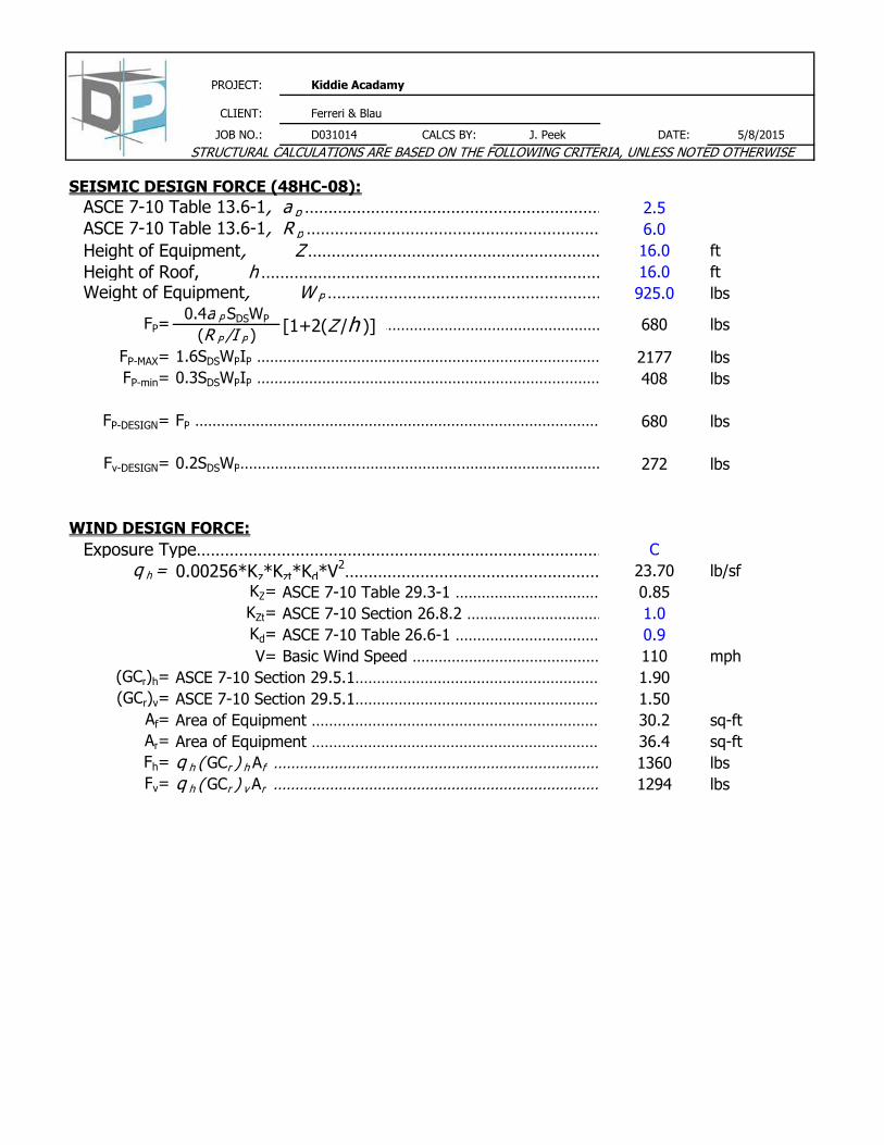
SEISMIC DESIGN FORCE (48HC-08): 4
ASCE 7-10 Table 13.6-1, a p ………………………………………………………………………………………………………2.5
ASCE 7-10 Table 13.6-1, R p ………………………………………………………………………………………………………6.0
Height of Equipment, Z …………………………………………………………………………..16.0 ft
Height of Roof, h …………………………………………………………………………..16.0 ft
Weight of Equipment, W P …………………………………………………………………………..925.0 lbs
0.4a P SDSWP
(R P /I P )
FP-MAX= 1.6SDSWPIP ……………………………………………………………………….. 2177 lbs
FP-min= 0.3SDSWPIP ………………………………………………………………………… 408 lbs
2.0
FP-DESIGN= FP …………………………………………………………………………………………….680 lbs
Fv-DESIGN= 0.2SDSWP…………………………………………………………………………… 272 lbs
WIND DESIGN FORCE:
Exposure Type………………………………………………………………………………… C 3
q h = 0.00256*Kz*Kzt*Kd*V2…………………………………………………………………………23.70 lb/sf
KZ= ASCE 7-10 Table 29.3-1 ……………………………………………0.85
KZt= ASCE 7-10 Section 26.8.2 ……………………………………………1.0
Kd= ASCE 7-10 Table 26.6-1 ……………………………………………0.9
V= Basic Wind Speed ……………………………………… 110 mph
(GCr)h= ASCE 7-10 Section 29.5.1…………………………………………………….. 1.90
(GCr)v= ASCE 7-10 Section 29.5.1…………………………………………………….. 1.50
Af= Area of Equipment ……………………………………………………………………..30.2 sq-ft
Ar= Area of Equipment ……………………………………………………………………..36.4 sq-ft
Fh= q h ( GCr ) h Af …………………………………………………………………………1360 lbs
Fv= q h ( GCr ) v Ar …………………………………………………………………………1294 lbs
FP= [1+2(Z /h )] …………………………………………… 680 lbs
STRUCTURAL CALCULATIONS ARE BASED ON THE FOLLOWING CRITERIA, UNLESS NOTED OTHERWISE

4 0
PROJECT: Kiddie Acadamy
CLIENT: Ferreri & Blau
JOB NO.: D031014 CALCS BY: J. Peek DATE: 5/8/2015
OVERTURNING DESIGN:
Equipment Dimensions:
Depth, D= 4.96 ft
Length, L= 7.34 ft
Height, H= 4.12 ft
SEISMIC:
Worst Case Uplift Reaction
Load Case: 0.6D+0.7E
R1= 15 lbs
Worst Case Downward Reaction
Load Case: 1.0D+0.7E
R2= -565 lbs
WIND:
Worst Case Uplift Reaction
Load Case: 0.6D+0.6W
R1= 449 lbs
Worst Case Downward Reaction
Load Case: 1.0D+0.6W
R2= -413 lbs
Net Uplift, Anchors Required
Net Uplift, Anchors Required
STRUCTURAL CALCULATIONS ARE BASED ON THE FOLLOWING CRITERIA, UNLESS NOTED OTHERWISE

4 0
PROJECT: Kiddie Acadamy
CLIENT: Ferreri & Blau
JOB NO.: D031014 CALCS BY: J. Peek DATE: 5/8/2015
ANCHORAGE RESULTS FOR UNIT TO CURB:
ALLOWABLE DOWEL SHEAR VALUES
ALLOWABLE SHEAR VALUE PER 2012 NDS TABLE 11K
0.625 4 0.5
Minimum embedment 4"
Load Duration increase taken as, CD=1.6 for seismic loading
VERIFY CAPACITY EXCEEDS DEMAND:
Number of Bolts in Shear= 4
Capacity Perpendicular to Grain= 704 lbs per bolt
Required Capacity Perpendicular to Grain= 204 lbs per bolt
ALLOWABLE WITHDRAWAL VALUES
ALLOWABLE WITHDRAWAL VALUE PER 2012 NDS TABLE 11.2A
0.625 4 0.50 1788
*Unthreaded upper 1.5" of embedment ignored for allowable withdrawal
Load Duration increase taken as, CD=1.6 for seismic loading
VERIFY CAPACITY EXCEEDS NEW DEMAND:
Number of Bolts in Withdrawal= 2
Capacity= 1788 lbs per anchor
Required Uplift= 225 lbs per anchor
VERIFY CAPACITY FOR COMBINED SHEAR AND TENSION:
ALLOWABLE DESIGN VALUE IN DIRECTION ALPHA PER NDS EQN 11.4-1
W'p………………………………………………………………………………………………………………………………..1788 LBS
Z'………………………………………………………………………………………………………………………………………………….704 LBS
a……………………………………………………………………………………………………………………………………. 48 DEG
Required =304 LBS
Force Ratio =0.29 Design OK
Z'a = (W'p)Z'
=1054 LBS(W'p)cos
2 a + Z' sin
2 a
Capacity =
ANCHOR
DIAMETER
EMBEDMENT
DEPTH
SPECIFIC
GRAVITY
ALLOWABLE
WITHDRAWAL*
ANCHOR
DIAMETER
EMBEDMENT
DEPTH
SPECIFIC
GRAVITY, G
ALLOWABLE SHEAR PARALLEL TO
GRAIN (LBS)
ALLOWABLE SHEAR
PERPENDICULAR TO GRAIN (LBS)
1200 704
STRUCTURAL CALCULATIONS ARE BASED ON THE FOLLOWING CRITERIA, UNLESS NOTED OTHERWISE
The new unit is to be installed with (4) 5/8" diameter lag screws, (1) in each corner, embedded 4" into
4x6 purlin