Embed Size (px)
Citation preview
SLIVE LIFE. TRAVEL WELL.Design Standards ManualStructuralDenver Internaonal AirportAirport Infrastructure Management
2016

January 2017 ii Denver International Airport
Copyright ©1989-2017 by Denver International Airport
All rights reserved No part of this manual may be reproduced or transmitted in any form or by any means, electronic or mechanical, including photocopying, recording, or by any information storage and retrieval system, without the permission in writing from the publisher. Printed in the United States of America
Structural Design Standards Manual Table of Contents
January 2017 iii Denver International Airport
Table of Contents
Chapter 1 - General ....................................................................................................................................................5 Section 501 - General .............................................................................................................................................5 Section 502 - Structural Codes and Standards ......................................................................................................5 Section 503 - Quality Assurance Program ..............................................................................................................5
Chapter 2 - Task Requirements by Phase .................................................................................................................7 Section 200 - Task Requirements by Phase ..........................................................................................................7 Section 201 - Schematic Design Requirements .....................................................................................................7 Section 202 - Design Development Requirements .................................................................................................7 Section 203 - 60% Design Review ..........................................................................................................................8 Section 204 - Final (100%) Review .........................................................................................................................8 Section 205 - Bid Document Requirements ............................................................................................................9 Section 206 - Bidding Period Requirements ...........................................................................................................9 Section 207 - Construction Period Requirements ...................................................................................................9
Chapter 3 - Structural Systems ............................................................................................................................... 10 Section 300 - Structural Systems ......................................................................................................................... 10 Section 301 - Foundations ................................................................................................................................... 10 Section 302 - Superstructure Types .................................................................................................................... 10
Chapter 4 - Structural Design .................................................................................................................................. 13 Section 400 - Structural Design ........................................................................................................................... 13 Section 401 - Passenger Terminal ....................................................................................................................... 15 Section 402 - Other Buildings - Minimum Floor Live Loads................................................................................. 16 Section 403 - Miscellaneous Structures Other Than Buildings ........................................................................... 23
Chapter 5 - Geotechnical ......................................................................................................................................... 24 Section 500 - Geotechnical .................................................................................................................................. 24 Section 501 - Geotechnical Conditions ................................................................................................................ 24 Section 502 - Subsurface Investigations.............................................................................................................. 25 Section 503 - Laboratory Testing ......................................................................................................................... 27 Section 504 - Foundation Design Criteria ............................................................................................................ 28 Section 505 - Slabs At Grade .............................................................................................................................. 33 Section 506 - Lateral Earth Pressure Design Criteria .......................................................................................... 35 Section 507 - Excavation Stability Design Criteria ............................................................................................... 38 Section 508 - Groundwater Control Criteria ......................................................................................................... 38 Section 509 - Protection of Adjacent Structures .................................................................................................. 41 Section 510 - Field Instrumentation ..................................................................................................................... 42
Appendix A - Abbreviations ..................................................................................................................................... 44 Appendix B – References ........................................................................................................................................ 46
Structural Design Standards Manual Preface
January 2017 iv Denver International Airport
Preface
The Denver International Airport (DEN) Design Standards have been developed to insure a unified and consistent approach to the thematic and technical design for the Denver International Airport. These standards are for use and strict implementation by all Consultants under contract to DEN, to Tenants, and all other Consultants under contract to any other entity for the design of projects at the Denver International Airport.
The Standards Manuals are intended to be working documents, which will be revised and updated, as required, to address the general, conceptual, design, and technical standards for all areas of design for the DEN.
This Design Standards Manual for the Denver International Airport has been prepared for use by competent, professionally licensed architectural and engineering Consultants under the direction of DEN Maintenance and Engineering or Tenants of DEN.
The Design Standards shall not be quoted, copied, or referenced in any bidding or construction contract documents. All information contained in these standards must be fully explained and shown in all bidding and contract documents.
The Design Standards Manuals are intended to be used as a whole, as each manual is complimentary to the others. In order to understand the overall thematic and design standards for the Denver International Airport, the manuals must be utilized together and not separated from the Design Standards Manuals as a whole.
The Consultant shall not reproduce, duplicate in any manner, transmit to other consultants or other entities or use in conjunction with other projects without the express written consent of Denver International Airport.
Structural Design Standards Manual Chapter 1 - General
January 2017 5 Denver International Airport
Chapter 1 - General
Section 501 - General
This manual establishes minimum criteria to which the structural systems must be designed to provide protection of life, health, and property in the environments provided.
Section 502 - Structural Codes and Standards
2006 International Building Code with 2008 Denver Building Code Amendments or latest edition
502.1 Applicable Standards
A. American Concrete Institute (ACI) ACI 318
B. American Institute of Steel Construction (AISC)
1. "Specification for the Design Fabrication, and Erection of Structural Steel for Buildings" including comments and supplements, Ninth Edition.
2. "Code of Standard Practice"
3. "Load & Resistance Factor Design", First Edition
4. "Specification for Structural Joints Using ASTM A325 or A490 Bolts"
5. "Engineering for Steel Construction, A Source Book on Connections"
C. American National Standards Institute, Inc. (ANSI)
1. A58.1 "Minimum Design Loads for Buildings and Other Structures"
D. American Welding Society (AWS) D1.1
1. "Structural Welding Code-Steel"
E. American Water Works Association (AWWA)
1. "Standard for Steel Tanks, Standpipes, Reservoirs and Elevated Tanks, for Water Storage" AWWA D-100-59
F. American Society of Testing Materials (ASTM)
1. Standard properties of miscellaneous building materials
G. Portland Cement Association (PCA)
1. Applicable Standards
H. Post-Tensioning Institute (PTI)
1. "Post-Tensioning Manual"
I. Prestressed Concrete Institute (PCI)
1. Applicable Standards
J. Miscellaneous standards for properties, manufacture and installation of specific items not fully covered by above standards.
Section 503 - Quality Assurance Program
The structural systems design shall be thoroughly coordinated by the Design Consultant with the work of all other trades. The contract drawings shall reflect a design as completely engineered as possible. Provide design loads for any connections that are to be designed by contractor. Provisions for attachment of equipment to structure are to be noted and support points located.

Structural Design Standards Manual Chapter 1 - General
January 2017 6 Denver International Airport
If the design of structural steel elements results in components that require nondestructive testing, that requirement must be indicated on the drawings. Nondestructive testing should only be specified where visual inspection by a certified inspector cannot provide reasonable assurance of structural integrity. Procedures, techniques, acceptance criteria, etc., shall conform to AWS D1.1 structural welding code and AWS B1.0 guide for nondestructive inspection of welds.
Refer to Standards and Criteria Design Standards Manual for the overall project quality control program. Note especially that the Design Consultants must submit a quality control program for review and approval prior to commencement of the work. There are specific quality assurance procedures required during the preparation of calculations, drawings, and specifications.
End of Chapter
Structural Design Standards Manual Chapter 2 - Task Requirements by Phase
January 2017 7 Denver International Airport
Chapter 2 - Task Requirements by Phase
Section 200 - Task Requirements by Phase
During the design phase of new facilities or facility improvements at the Denver International Airport, and after the initial design scope development stage, submittals are required for review by the owner at the following stages of completion. The owner's comments, corrections, notations, etc., shall be revised by the Design Consultant and incorporated into the design before the next stage of completion is submitted. Refer to Standards and Criteria Design Standards Manual for the material included in each phase.
Section 201 - Schematic Design Requirements
Refer to Standards and Criteria Design Standards Manual.
This phase includes a preliminary one-line schematic design layout of the structural systems, alternative systems if appropriate, and a cost estimate refined to the 15% level. Conduct meetings with owner, facility users, and operators for design input.
Section 202 - Design Development Requirements
Refer to Standards and Criteria Design Standards Manual.
Perform design development tasks for the contract that shall include general areas of work for floors and roofs, floor framing, columns, bracing, foundations, and miscellaneous structures.
202.1 Calculations
Perform definitive structural calculations. They should include sizing for all main components and most secondary members exclusive of bracing and connections.
202.2 Plans and Elevations
A. Plans and elevations showing major components; general arrangements; and location of all major framing
B. Location of doors, windows, stairs, and other openings
C. Lateral force resisting systems. Define systems and locate diaphragms, braces, and moment resisting connections
D. Layout of standards, schedules, and details.
Indicate scope of information to be provided in final design drawings.
E. Standard drawings, schedules, charts, and details.
Layout drawings indicating information to be supplied in subsequent phases. Include any information available at this time to show concepts of construction details, materials, and overall structural systems.
202.3 Coordination Requirements
A. Coordinate overall plan and elevation views with Architectural Design Consultant.
B. Coordinate all access openings in floors and walls with Architectural Design Consultant.
C. Coordinate all floor and wall penetrations for ducts, pipes, conduits, etc. with mechanical and electrical Design Consultants.
D. Coordinate locations, sizes, and loadings from all equipment to structural system.
E. Meet with any other consultants at review meetings to verify direction and progress during design development work.

Structural Design Standards Manual Chapter 2 - Task Requirements by Phase
January 2017 8 Denver International Airport
202.4 Specification Requirements
Outline specifications including brief technical descriptions of all system, members, and materials.
202.5 Cost Estimates
A. Prepare preliminary cost estimates on a per square foot or similar basis.
B. Preliminary cost estimate shall include a list of quantities of materials and unit prices.
C. Prepare cost estimates for alternative support systems, including schedule impacts of different systems.
202.6 Documentation Requirements
Design development documents to be completed for the structural systems shall include the following:
A. Preliminary Design Analysis Report. For information about this report, refer to Standards and Criteria Design Standards Manual
B. Drawings shall be prepared using the AutoCAD system approved by the City. Refer to EDCI Compliance Design Standards Manual.
Drawings shall include, but not be limited to, the following:
A. Foundation plan showing all footings, grade beams, walls, trenches, etc. Locate and orient columns and equipment foundations.
B. Structural floor and roof plans.
Types and dimensions of floors, including grating and floor plates. Define all major equipment supports, openings, framing systems.
C. Elevations and building sections.
Locate all floor levels, beams, columns, struts and framing around openings. Locate braces or moment resisting connections.
D. Standard drawings, details, schedules, and charts.
Show standard details selected at this phase for bracing, girt system, beam connections, concrete slab edges, handrails, ladders, stairs, etc. Provide format for schedules for columns, connections, foundations, etc.
Section 203 - 60% Design Review
Refer to Standards and Criteria Design Standards Manual
Tasks to be completed by the 60% completion level:
A. Rough draft of specifications.
B. Drawings - Plans should be at least 80% complete.
C. Elevations - Should be at least 70% complete.
D. Details - Should be at least 50% complete.
E. Schedules - Should be at least 70% complete.
F. Updated and completed calculations.
G. All notes, details, schedules and charts shown.
H. Identify, in tabular form, work required to complete drawings.
Note that a Final Design Analysis Report is required. Refer to Standards and Criteria Design Standards Manual.
Section 204 - Final (100%) Review
All work complete and checked. Submit for final review.

Structural Design Standards Manual Chapter 2 - Task Requirements by Phase
January 2017 9 Denver International Airport
Refer to Standards and Criteria Design Standards Manual
Section 205 - Bid Document Requirements
All comments and corrections from final review have been incorporated.
Refer to Standards and Criteria Design Standards Manual
Section 206 - Bidding Period Requirements
Once the project is ready for bidding purposes, a complete set of project documents shall be submitted to the Owner along with any addenda.
Refer to the Standards and Criteria Design Standards Manual for an explanation of the Design Consultant's responsibilities during bidding.
Section 207 - Construction Period Requirements
Refer to Standards and Criteria Design Standards Manual.
End of Chapter
Structural Design Standards Manual Chapter 3 - Structural Systems
January 2017 10 Denver International Airport
Chapter 3 - Structural Systems
Section 300 - Structural Systems
The structural system of each building, structure, or portion thereof shall be selected to support its own weight and that of all structural and nonstructural components attached to it. It must also resist all forces applied to it from pedestrian or vehicular traffic, wind, seismic movement, thermal movement, and all loads from equipment or other sources.
The structural systems shall be selected to provide a safe, healthy, and comfortable environment for all persons or equipment occupying or affected by their presence. They shall also be coordinated for a pleasing, unified appearance, efficient circulation of personnel and other traffic, and economical construction.
Section 301 - Foundations
Foundations for all structures are to provide a supporting platform on which to erect the structure. They shall resist all loads from the superstructure and all lateral or swelling forces from the soil without exceeding acceptable limits for bearing pressures, pile capacities, or settlement. Uplift of any part of a structure is also to be resisted by anchorage to the foundation.
A subsurface investigation will be required for each facility and a report prepared that will include a recommended foundation system and design and construction parameters.
301.1 Shallow Foundations
Shallow foundations are those that are constructed a relatively short distance below grade and derive their support from bearing pressure on the underlying soil. Tops of slabs or mats will be located as required for ground floor or basement floor elevations. Footings subject to outside temperatures are to be located below frost penetration depth, a minimum of 3'-0" below ground surface. Soils investigations will be made to determine permissible bearing pressures.
301.2 Deep Foundations
Deep foundations shall be employed where shallow foundations do not provide satisfactory bearing capacity or resistance to settlement or heaving. Footings or mats are supported by piles or drilled shafts. Load-carrying capacity is provided by end bearing, skin friction, or a combination of both. Type of pile or shaft will be determined from soils investigation. Select type of deep foundation that will be most capable of supporting the imposed loads efficiently and economically.
Section 302 - Superstructure Types
302.1 Steel Structures
Steel structures are essentially frames that support floors, roofs, and walls of a building. Vertical loads from floors, roofs, and other structural components are supported on beams, joists, or trusses that are in turn supported by columns. Walls are supported by beams or by girts spanning between columns.
Lateral loads from wind, seismic or temperature movements, etc. are resisted by shear walls, diagonal bracing, or by moment resisting members and connections.
Materials used in steel structure shall be those with proportions and properties that provide the best performance in the overall design. The use of stainless, high strength or corrosion resistant steels may be warranted in special areas.
Members used in fabricating a steel frame may be rolled sections, factory built joists and joist girders, or custom designed and built up sections. Connections may be welded, bolted or a combination of both. Composite design may be used where required or economically advantageous.
Connections both bolted and welded, may be designed by the Design Consultant or the fabricator. If designed by the Design Consultant, they must be thoroughly detailed in the construction documents. If designed by the fabricator, the drawings must clearly define that responsibility and provide all the design loads, restrictions, and
Structural Design Standards Manual Chapter 3 - Structural Systems
January 2017 11 Denver International Airport
special provisions. Connections designed by the fabricator must be under the direct supervision of a professional engineer registered in the State of Colorado. The construction documents must specify that the fabricator furnish documentation, under a licensed professional engineer's seal and signature, that a professional engineer has designed the connections.
In either case, the Design Consultant must review and approve the connection details and retain responsibility for conformance with overall design requirements and information given in the construction documents. However, the review and approval by the Design Consultant do not relieve the fabricator and his professional engineer of their design responsibility.
302.2 Cast-In-Place Concrete Structures
Cast-in-place structures are essentially frames of reinforced concrete members, cast in their final position at the construction site. The typical structure is a moment resisting frame with connecting members placed to form monolithic joints. Reinforcing steel extends through joints to provide continuity between members.
Cast-in-place members and components may include, but are not limited to, foundations, columns, beams, floors, walls, tunnels, and machinery pedestals.
Construction joints may be used between successive pours. Extend reinforcing bars through joints to splice onto bars in following pours.
Where appropriate, post-tensioning may be used with the cast-in-place construction. It may be used to limit deflections of long-span members, to develop frame action, to control cracking in slabs, etc.
Forms for concrete members are to be constructed of materials that have the strength to support the fluid concrete and any loads that may be applied during construction. Form surfaces that are in contact with the concrete must be of a material that will give the concrete a satisfactory finish. Reuse of forms can be achieved by designing members of the same sizes where practical.
Foundations are to be placed on the earth below them. Vertical sides of excavations may be used for forming where the earth is capable of retaining its excavated shape. Forming of sides is required for all exposed foundations.
302.3 Precast Concrete
Precast concrete structures or members are those cast other than in their final position. They may be standard manufactured items or custom designed. Precast members may include, but are not limited to,
A. Floor and roof deck panels
B. Wall panels
C. Columns or posts
D. Beams
E. Other precast items are wall copings, door and window frames, stair segments, etc.
Precast members may be prestressed (pre-tensioned or post-tensioned) or non-prestressed. All are to be reinforced to give the members their desired strength and durability.
Attachment to other members of the overall structure is to be made by bolting, welding, anchoring by use of dowels into cast-in-place segments, or other approved methods.
Design of precast elements must include the forces due to removing sections from forms, lifting, transporting, anchoring, etc., in addition to those forces to be resisted after the element is incorporated into the framing system.
302.4 Tilt-Up Concrete
Tilt-up construction is a special case of pre-cast concrete. Wall panels are poured in beds or on the grade floor slab with embedded devices for attachment to the building frame. After curing, the panels are tilted to a vertical position and connected to the building. Tilt slabs may serve as the building frame or merely as a skin enclosing it.

Structural Design Standards Manual Chapter 3 - Structural Systems
January 2017 12 Denver International Airport
302.5 Concrete Masonry Units (Concrete Blocks)
Concrete blocks are used for construction of both interior partitions and exterior walls. Depending on the size and use of the buildings, walls may be load bearing and provide the entire means of resisting vertical and lateral loads. Block walls may also be incorporated as shear walls to resist lateral loads in other types of building frames.
Depending on the size or use, concrete block walls may be reinforced or non-reinforced. Special purpose blocks are available for anchorage of various items, spanning openings, etc.
End of Chapter
Structural Design Standards Manual Chapter 4 - Structural Design
January 2017 13 Denver International Airport
Chapter 4 - Structural Design
Section 400 - Structural Design
The structural systems of each building or portion thereof shall provide a safe environment for all persons and equipment occupying or affected by it. All forces which may be expected to act upon it shall be considered in designing and members proportioned to resist these loads without exceeding stresses, deflections, or other limits defined by the applicable codes and standards. Loads to be used in designing include, but are not limited to the following:
400.1 Dead Load
Dead load is defined as the weight of structure, supported structures and building components, and all stationary equipment and furnishings. Floor dead load includes ceilings and services hung from the floor.
400.2 Live Load
A. Temporary loading imposed by snow, traffic, machines, etc.
B. Live loads for small spaces, toilet rooms, corridors, etc. should be the same as the live load for the surrounding spaces if the surrounding live load is heavier.
C. Catwalks and equipment access platforms shall be designed for at least 40 psf live load. Lay-down areas may require substantially heavier loads.
Airports need to be flexible to accommodate various uses of space throughout the life of airport operations. Therefore, it is the responsibility of the Design Consultant to examine spaces that may be used for something other than for what they were initially intended. Use the higher loading requirement when it is reasonably justifiable. (i.e., airline office space, due to future remodeling, may become circulation corridor space. Therefore, design for 125 psf.) All assumptions should be listed in the Preliminary Analysis Report for comment and/or approval by PM.
400.3 Snow Load
Design for load specified in the proposed Denver Building Code Amendments. Roof loads shall account for roof slopes and potential accumulation of snow at valleys, parapets, roof structures, and offsets of roofs of uneven configuration.
400.4 Wind Load
Design for a basic wind speed of 85 mph and exposure category C. Design pressures shall be calculated for individual structures on basis of shape, height, size, and locations as specified by ANSI A58.1, but not less than 30 psf for exterior walls and any interior partitions subject to jet blast.
400.5 Earthquake Load
Design for forces specified by UBC-1988 for Seismic Zone 1.
400.6 Other Loads
A. Fire lane loads
Design for worst condition for AASHTO HS20-44 or actual firetruck loads including tankers, and outrigger loads.
B. Mechanical rooms
Design for actual equipment loads, but not less than 125 psf.
C. Elevators
Use loading data from manufacturer for specific elevators used with 100% impact.

Structural Design Standards Manual Chapter 4 - Structural Design
January 2017 14 Denver International Airport
D. Computer rooms
Design for actual equipment loads, but not less than 125 psf.
E. Lateral loads
The Structural Design Consultant shall submit a plan showing the path of resistance for all lateral loads as part of the design development (35%) submittal.
F. Handrails and railing systems
Require contractor to design, engineer, fabricate, and install handrails and railing systems to withstand the following structural loads without exceeding the allowable design working stress of the materials for handrails, railing systems, anchors, and connections. Apply each load to produce the maximum stress in each of the respective components comprising handrails and railing systems.
G. Top rail of guardrail system
Capable of withstanding the following loads applied as indicated:
1. Concentrated load of 200 lbf applied at any point nonconcurrently, in any direction.
2. Uniform load of 50 lbf per linear foot applied nonconcurrently, in any direction.
3. Concentrated and uniform loads above need not be assumed to act concurrently.
H. Handrails not serving as top rails
Capable of withstanding the following loads applied as indicated:
1. Concentrated load of 200 lbf applied at any point nonconcurrently
2. Uniform load of 50 lbf per linear foot applied nonconcurrently, vertically downward or horizontally
3. Concentrated and uniform loads above need not be assumed to act concurrently.
I. Infill area of guardrail system
Capable of withstanding a horizontal concentrated load of 200 lbf applied to one square foot at any point in the system including panels, intermediate rails, balusters, or other elements composing the infill area.
Above load need not be assumed to act concurrently with uniform horizontal loads on top rails of railing system in determining stress on guard.
J. Glass-supported railing systems
Capable of withstanding loads indicated for top rails and infill area of guardrail systems based on safety factor of 4, with each section of top rail supported by a minimum of 3 glass panels or by another means so that it remains in place should one panel fail.
K. Interior walls and partitions
Design to resist all loads to which they are subjected but not less than 5 pounds per square foot applied perpendicular to the walls. Deflection shall not exceed L/360 of the span.
When the structural framing members, either concrete or steel, are left exposed as an architectural element, coordinate the finish of these members with the Architectural Design Consultant.
400.7 Major Structural Components
A. Roofs
Roofs over all enclosed areas shall protect the interiors from the outside environment. Forces acting on the roof include the dead load of the roof and all structure and equipment supported, live loads including snow and traffic or other temporary forces, and wind effects. Any roof that may become a future floor shall be designed for a minimum uniform live load of 100 psf or greater load if required.
B. Walls and partitions
Structural Design Standards Manual Chapter 4 - Structural Design
January 2017 15 Denver International Airport
All walls and partitions shall be designed to support their own weight and any building components or equipment supported by them. Lateral loads from wind or earthquake forces shall be applied as well as collision or other forces. Walls to be stiffened or provided with lateral support by girts as indicated.
C. Main structural framing system
All beams, columns, bracing, and other parts of the main load-resisting frame shall be designed to resist gravity, lateral, and thermal loads applied directly or through floors, roofs, and walls. Reactions from traffic or mechanical systems shall be included. Member types and sizes are to be selected to give a uniform appearance. Lateral loads are to be resisted by shear walls, diagonal bracing, moment-resisting members and connections, or combinations thereof.
D. Foundations
Design foundations to support structures on the underlying soil. All gravity and lateral loads are to be resisted without exceeding permissible loading or total or differential settlement limits determined from soils investigations. Uplift of any portion to be resisted by foundation. Foundations may be slabs on grade or piles, individual spread footings, or footings on piles or drilled shafts.
E. Floors
Floors are to be designed for the floor dead load plus uniform or concentrated live loads pertinent to given areas. Include loads from all equipment, furnishings, piping, lighting and structures supported upon or suspended from them. Design all stairs, ramps, escalators, and walkways for 100 psf (pounds per square foot) except as noted for individual zones or buildings.
F. Ground transportation and parking lots
Ground transportation and parking lots that are exposed to weather shall be designed for snow removal equipment loads.
Section 401 - Passenger Terminal
401.1 Minimum Floor Live Loads
The Design Consultant is responsible for verifying all loads.
A. Ticketing level
Design for 100 psf except for areas occupied by baggage conveyors or where baggage conveyors could potentially be hung from the floor where minimum live load shall be 125 psf.
B. Baggage claim
Design for 100 psf except for areas occupied by baggage conveyors and distribution equipment, including bag carousels. Design these areas for actual equipment loads, but not less than 160 psf. Any conditions, such as multiple levels of suspended conveyors that may exceed the additional 60 psf shall be investigated in detail by the Design Consultant.
C. Feature piedmont (Observation lounge)
Design for 100 psf.
D. Train stations
1. Security (office, lockers, restrooms and showers)
Design for 100 psf except where communications, mechanical, or other equipment exceeds this.
2. Exit and boarding platforms
Design for 100 psf. With dead load, include weight of barriers or other structures supported.
3. Train support structures
Structural Design Standards Manual Chapter 4 - Structural Design
January 2017 16 Denver International Airport
Design for dead load of structure, track and accessories, stops, etc. Live load to include weight of loaded train (to be supplied by manufacturer), impact, and any lateral and longitudinal loads resulting from the operation of the train.
E. Concessions and service
Design for 100 psf in public areas and 125 psf in storerooms. Consider weights of vending machines, appliances, and miscellaneous equipment and increase live loads as required.
F. Restrooms
Design for the same load as the adjacent occupancy. For example, restrooms in ticketing areas shall be designed for 125 psf; in baggage claim areas, 160 psf.
G. Ground transportation levels
1. For areas usable by passenger cars only and height limitations do not allow busses or trucks, design for uniform live load of 50 psf or individual wheel loads of 2000 lbf acting on areas of 20 in.2, spaced 5 feet on center in any direction; whichever produces the greater stress.
2. For areas usable by busses and trucks and any area that may be used for busses and trucks in the future, design for lane loads or axle loads as specified by American Association of State Highway and Transportation Officials (AASHTO) latest edition "Standard Specifications for Highway Bridges," with interim specifications. Design for HS20-44 loads plus impact unless reduced loading is approved by the City and County of Denver.
H. Baggage system
A structural analysis shall be performed by the Design Consultant regarding the baggage system including both static and dynamic loadings.
I. Vibrating loads
The Design Consultant shall address the problem of transfer of unacceptable vibrations to the public areas including hold rooms, waiting rooms, concession areas, observation lounge, restaurants, etc. Isolation joints, isolation dampers, absorbers or other means shall be used to control the transfer of vibrations from the baggage system, tug drive, conveyors, moving walkways, trains, or any other source.
Section 402 - Other Buildings - Minimum Floor Live Loads
402.1 International Concourse
Use same live loads as for corresponding use areas in Terminal. For areas where baggage conveyors could potentially be hung, follow the guidelines for the Terminal Ticketing Level. Comply with the requirements for the baggage system and vibrating loads stated in the Terminal section.
A. Public access and waiting areas
Use 100 psf.
B. Train stations
Use 100 psf on platforms, design train support structure for dead load of structure, track and accessories, stops, etc. Live load to include weight of loaded train (to be supplied by manufacturer), impact and any lateral and longitudinal forces resulting from the operation of the train.
C. Concessions and services
Design for 100 psf in public areas and 125 psf in store rooms.
D. Restrooms
Design for live loads for the occupancy with which they are associated, but not less than 100 psf.
E. Escalators and moving walks
Structural Design Standards Manual Chapter 4 - Structural Design
January 2017 17 Denver International Airport
Design for at least 100 psf live load plus the added equipment loads. Dimensional requirements for end pits and the depth between the end pits shall be sized to accommodate all qualified escalator and moving walk systems. For moving walks, support points shall be provided at the column lines only. Any additional supports required for a particular moving walk system shall be provided by the manufacturer of that system.
402.2 Domestic Concourse
Use same live loads as for corresponding use areas in Terminal. For areas where baggage conveyors could potentially be hung, follow the guidelines for the Terminal Ticketing Level. Comply with requirements for the DCV baggage system and vibrating loads stated in the Terminal section.
A. Public access and waiting areas
Use 100 psf.
B. Train stations
Use 100 psf on platforms, design train support structure for dead load of structure, track and accessories, stops, etc. Live load to include weight of loaded train (to be supplied by manufacturer), impact and any lateral or longitudinal loads resulting from the operation of the train.
C. Concessions and services
Design for 100 psf in public areas and 125 psf in storerooms.
D. Restrooms
Design for live loads for the occupancy with which they are associated, but not less than 100 psf.
E. Escalators and moving walks
Design for at least 100 psf live load plus the added equipment loads. Dimensional requirements for end pits and the depth between the end pits shall be sized to accommodate all qualified escalator and moving walk systems. For moving walks, support points shall be provided at the column lines only. Any additional supports required for a particular moving walk system shall be provided by the manufacturer of that system.
402.3 Control Tower
Refer to the FAA Web site.
402.4 Hotel
A. Lobby, meeting, and public assembly rooms
100 psf
B. Sleeping rooms and corridors on sleeping floors
40 psf
C. Restaurants and kitchens
100 psf
D. Concessions and services
100 psf in public areas, 125 psf for storerooms.
E. Stairs, corridors on public assembly levels, and miscellaneous pedestrian traffic areas
100 psf.
F. Offices
50 psf + 20 psf partitions
G. Restrooms
Structural Design Standards Manual Chapter 4 - Structural Design
January 2017 18 Denver International Airport
Design for live loads for the occupancy with which they are associated, but not less than 50 psf.
H. Parking garages
For areas usable by passenger cars only, and height limitations do not allow busses or trucks, design for uniform live load of 50 psf or individual wheel loads of 2000 lbf acting on areas of 20 in.2, spaced 5 feet on center in any direction; whichever produces the greater stress. For areas usable by busses and trucks, design for lane loads or axle loads as specified by American Association of State Highway and Transportation Officials (AASHTO) latest edition "Standard Specifications for Highway Bridges" with interim specifications. Design for HS20-44 loads plus impact unless reduced loading is approved by the City and County of Denver.
The designer shall investigate whether window washing will be manual or automated and consider related loads in designing supports for washing system equipment and personnel.
402.5 Structured Parking
A. Vehicular loading
1. For areas usable by passenger cars only, and height limitations do not allow busses or trucks, design for uniform live load of 50 psf or individual wheel loads of 2000 lbf acting on areas of 20 in.2, spaced 5 feet on center in any direction; whichever produces the greater stress.
2. For areas usable by busses and trucks, and any areas that may be used for busses and trucks in the future, design for lane loads or axle loads as specified by AASHTO- latest edition "Standard Specifications for Highway Bridges" with interim specifications. Design for HS20-44 loads plus impact.
B. Garage roofs
Garage roofs shall be designed for a non-reducible live load of 55 psf that includes snow and snow-removal equipment. Garage roofs that provide access for fire trucks shall be designed for the live loads required. Contact the Fire Department for specifications.
Provide positive roof slopes to ensure drainage. Consider the use of epoxy-coated reinforcing, microsilica concrete, and/or silane or siloxane sealers to reduce chloride penetration and corrosion of reinforcing in all slabs subject to freeze-thaw cycles and chemical deicing materials.
C. Stairs, ramps, etc.
100 psf
D. Restrooms
Design for live loads for the occupancy with which they are associated, but not less than 50 psf.
402.6 Parking Toll Plaza
A. Office, restrooms, locker areas
50 psf
B. Store rooms
125 psf.
C. Toll collection, communications, and miscellaneous equipment live loads as provided by manufacturers
402.7 Office Building
A. Offices
0 psf + 20 psf partitions.
B. Restrooms
Design for live loads for the occupancy with which they are associated, but not less than 50 psf.
Structural Design Standards Manual Chapter 4 - Structural Design
January 2017 19 Denver International Airport
C. Lobby, main access passageways, stairs, etc.
100 psf
D. Store rooms (light storage)
125 psf.
E. File and computer rooms
File and computer rooms shall be designed for heavier loads based on weights of actual equipment to be provided, but not less than 125 psf.
402.8 Central Power Plant
Central power plant houses equipment for providing steam, chilled water, compressed air, and other items to all the main airport buildings. Structural design to include loads for the support of all mechanical, electrical, and other equipment, floors, platforms, stairs, hoisting equipment and other items used. Loads for these items to be provided by manufacturers. Other loads not governed by specific equipment are as follows:
A. Offices
50 psf + 20 psf partitions and miscellaneous dead load.
B. Restrooms
Design for live loads for the occupancy with which they are associated, but not less than 50 psf.
C. Storage
125 psf or as required for heavy parts.
D. General access floors, platforms, and stairs
100 psf.
E. Platforms provided for access to equipment
As indicated for lay down or transport of heavy parts and equipment.
402.9 Maintenance Facility
A. Offices, restrooms and lockers - 50 psf.
B. Storage - 125 psf or larger loads such as 250 psf for heavy storage, based on specific supplies or equipment.
402.10 Air Cargo Facility (Handling and Short-Term Storage on Air Cargo)
A. Offices, lockers, restrooms - 50 psf
B. Storage areas - 250 psf.
C. Main floor loading - design for traffic and storage loads from cargo handling equipment (forklifts, carts, tugs, cranes, etc.). Use design loads for specific items used.
402.11 Aircraft Hangars
A. Small hangars
Maintenance performed on small aircraft from the ground floor or platforms and machines operating from the ground floor.
1. General facilities (offices, restrooms, lockers, etc.)
50 psf + 20 psf partitions and miscellaneous dead load.
2. Storage (light)
125 psf.
Structural Design Standards Manual Chapter 4 - Structural Design
January 2017 20 Denver International Airport
3. Main floor
Design for loading from aircraft, highway type trucks, cranes, and miscellaneous vehicles used for transporting aircraft engines, airframe assemblies, and parts.
4. Roof system
Design for roof loads, support of HVAC and other mechanical, electrical, or other suspended equipment and access catwalks and platforms.
B. Large hangars
Design for all maintenance of large aircraft including inspection, repair, and major overhaul.
1. General facilities (offices, restrooms, lockers, etc.)
50 psf + 20 psf partitions and miscellaneous dead load.
2. Storage (light and heavy)
Light 125 psf and heavy 250 psf.
3. Main floor
Design for loading from specified aircraft in applicable zones and from aircraft tugs in others. Provide jacking points in floor for supporting aircraft without wheels. Design covers for trenches, manholes, and pits for traffic load applicable in specific areas.
4. Roof system
Design for usual roof loads support of HVAC and other mechanical, electrical, or other suspended equipment and access catwalks and platforms. Include loading to roof system from movable platforms providing access for servicing and overhaul of aircraft.
402.12 Flight Kitchens
A. General facilities (offices, restrooms, lockers)
50 psf + 20 psf partitions and miscellaneous dead load.
B. Pedestrian traffic (stairs, main entry and exit corridors)
100 psf.
C. Kitchens
100 psf except where exceeded by loading from specific appliances, mechanical, or other equipment.
D. Storage
125 psf minimum or as required for storage of specific foods, utensils, or equipment.
E. Loading and receiving docks
Design for vehicular live loads from the largest trucks, tugs, tractors, or other vehicles which may use any specific area.
402.13 Snow Removal Equipment Facilities
A. General facilities (offices, restrooms, lockers)
50 psf
B. Storage
125 psf for light storage.
C. Storage
250 psf for heavy storage.
Structural Design Standards Manual Chapter 4 - Structural Design
January 2017 21 Denver International Airport
D. Main floor loads
Design for heaviest vehicles to be stored or serviced. Design for wheel loads directly on floor or supported by lifts or hoists. Servicing equipment and any mechanical or electrical equipment must be considered.
402.14 Aircraft Rescue and Firefighting Facility (ARFF)
See Snow Removal Equipment Facility for loads.
402.15 Rental Car Support Facility
A. General Facilities (offices, restrooms, lockers)
50 psf
1. For areas usable by passenger cars only, and height limitations do not allow busses or trucks, design for uniform live load of 50 psf or individual wheel loads of 2000 lbf. acting on areas of 20 in.2, spaced 5 feet on centers in any direction; whichever produces the greater stress.
2. For areas occupied by equipment used in cleaning, repairing, lubricating and refueling automobiles, design for actual weights of these items, but not less than 100 psf.
B. Storage (light)
25 psf.
402.16 Auto Service Station
A. General facilities (office, restrooms)
50 psf
B. Garage and servicing areas
1. 100 psf or 2000 lbf wheel loads acting on areas of 20 in.2, spaced 5 feet on center in any direction; whichever produces the greater stress.
2. If truck servicing is provided, increase loads for vehicles included. Areas supporting any servicing or building equipment to be designed for their support if the loads exceed the vehicle loads.
3. For areas occupied by equipment used in cleaning, repairing, lubricating and refueling automobiles, design for actual weights of these items, but not less than 100 psf.
C. Storage
125 psf for supplies, parts, etc. plus parking for towed cars.
402.17 Aircraft Fueling Control Facility
A. General facilities (office, restroom, lockers)
50 psf
B. Control and monitoring center, small repair area
100 psf.
402.18 General Aviation Facilities (Small Aircraft Services)
A. General facilities (offices, restrooms)
50 psf
B. Business offices, concessions, and services
100 psf.
C. Storage areas

Structural Design Standards Manual Chapter 4 - Structural Design
January 2017 22 Denver International Airport
125 psf.
D. Maintenance areas, small aircraft
Design for heaviest aircraft or maintenance vehicle to be stored or serviced, but not less than 250 psf.
402.19 Communications Center
A. General facilities (offices, restrooms)
50 psf + 20 psf partitions and miscellaneous dead load.
B. Access passageways, stairs, etc.
100 psf.
C. Telephone switchgear and equipment
250 psf.
402.20 Security Guard House
A. Office and restroom
50 psf
402.21 Aviation Museum
A. General facilities (office, restrooms)
50 pcf + 20 psf partitions and miscellaneous dead load.
B. Pedestrian traffic areas, stairs, exits, and entries
100 psf.
C. Counters, display cases, etc.
100 psf.
D. Support for large displays (aircraft, etc.)
Design floors for large uniform or concentrated loads exceeding nominal uniform loads in all display areas. Design roof for suspension of aircraft. Location and magnitude of loads to be determined by weight of aircraft to be accommodated.
402.22 Warehouse Facility
A. General facilities (offices, restrooms)
50 psf
B. Storage areas
Load to be determined from proposed use, but never less than 250 psf.
C. Main floor loading and truck docks
Check design for traffic and storage loads from handling equipment (forklifts, carts, tugs, cranes, etc.).
402.23 Bulk Storage Facility
Special structure for storage of bulk sand and salt.
A. Design walls for lateral loads from sand and salt at rest, as well as dynamic loads, due to filling of bunkers and impact from front-end loaders.
B. Provide treatments or coatings as may be appropriate for abrasion and corrosion.
Structural Design Standards Manual Chapter 4 - Structural Design
January 2017 23 Denver International Airport
Section 403 - Miscellaneous Structures Other Than Buildings
The Design Consultant is responsible for verifying all loads. Check all aircraft loads, tug loads, firefighting, and ARFF equipment, etc.
403.1 Pedestrian Bridges
The minimum live load for the bridge deck shall be 100 psf. Where use by small vehicles is anticipated increase live loads accordingly.
403.2 Highway Bridges
Contact the DEN Project Manager
403.3 Aircraft Bridge Structures (All Bridges, Tunnels, Culverts and Other Structures Supporting Aircraft on Runways, Taxiways, or Aprons)
Contact the DEN Project Manager
403.4 Lighting and Sign Supports
Design lighting and sign supports, including poles, sign bridges, arms, and foundations for loads and criteria from following AASHTO specification: "Standard Specification for Structural Supports for Highway Signs, Luminaries, and Traffic Signals," – latest edition.
403.5 Retaining Walls
Retaining wall design shall be in accordance with applicable codes. For walls related to roadways use AASHTO and for others follow IBC.
Design for lateral soil and surcharge pressures and for any other loads supported by walls. Effect of wall movement from expansive soil pressures shall be included. Use safety factors against sliding and overturning as specified by applicable codes, but not less than 1.5. Provide drains on high sides to prevent excessive pressures in saturated backfill. Drains may be perforated pipe or gravel wrapped in geofabric. Provide weep holes at frequent intervals, generally less than 8 feet.
403.6 Tunnels
Contact the DEN Project Manager.
End of Chapter
Structural Design Standards Manual Chapter 5 - Geotechnical
January 2017 24 Denver International Airport
Chapter 5 - Geotechnical
Section 500 - Geotechnical
In this report, Geotechnical Criteria for design of structures at the Denver International Airport (DEN) are presented. Design of foundations for structures at the DEN will require site-specific evaluations of appropriate foundation types and supporting capacities, as well as estimates of settlement or heave, and other geotechnical considerations.
Section 501 - Geotechnical Conditions
501.1 General
Site-specific subsurface exploration should be performed at all proposed structure locations. Criteria for the explorations are presented in subsequent sections of this report. The following subsections include discussions of general subsurface conditions and the other site-specific considerations, which should be addressed during foundation designs for DEN structures.
501.2 Subsurface Conditions
A Preliminary subsurface exploration was conducted at the DEN site by AA Engineers & Associates, Inc. (AAE) (Reference 1). One hundred thirty-three borings were drilled. This subsurface information should be used in planning subsurface explorations for structures. The complete AAE preliminary exploration report is available from City and County of Denver.
The AAE borings generally encountered clay and silt soils overlying weathered claystone, siltstone, and sandstone bedrock. Depth of the natural soils was generally reported to vary between 5 (five) and 20 (twenty) feet. Localized groundwater was reported.
501.3 Swelling Soils
Clay and weathered claystone bedrock with swell potential were reported by AAE (Reference 1). Samples exhibited varying swelling characteristics, as swell percentages up to about 5 (five) percent and swell pressures up to about 15,000 (fifteen thousand) psf were noted.
The reported swell characteristics should not be used directly for structural design purposes, except for facilities at locations where the specific data were obtained. Rather, subsurface explorations should be planned to evaluate the structure-specific occurrence of swelling soils and weathered bedrock.
501.4 Erosion Potential
Surficial soil types reported at the DEN site by AAE included clay, silt, and sand (Reference 1). Each of these soil types is potentially highly erodible by wind and water. Construction sequencing and architectural detailing should take into consideration the potential for erosion and the associated fugitive dust potential. Appropriate measures should be implemented during design of structures and landscaping in order to control potential erosion problems at DEN building sites.
501.5 Frost Susceptibility
Soils reported at the DEN site by AAE (Reference 1) included clay, silt and sand soils that may be moderately to highly frost susceptible. Of the reported soils, silts generally exhibit the greatest heave tendencies upon freezing.
Subsurface explorations should assess the occurrence of frost susceptible soils. Generally, non-frost susceptible soils should be used within 3 (three) feet of the ground surface, particularly beneath paved surfaces.
501.6 Groundwater
Groundwater was reported in some borings at the DEN site by AAE (Reference 1). Groundwater was encountered in drainages and as localized perched groundwater tables. Future regrading, coupled with landscape watering and altered run-off characteristics, could create localized perched groundwater tables at almost any DEN
Structural Design Standards Manual Chapter 5 - Geotechnical
January 2017 25 Denver International Airport
location. It is possible that the resulting increased moisture contents could result in heave of potentially swelling clays and weathered bedrock.
Structure specific subsurface explorations should evaluate the existing groundwater conditions at building sites, and the potential for development of perched groundwater tables. Building plans should account for the potential effects of perched groundwater tables and the generally increasing moisture contents of subsurface materials.
501.7 Soil Reactivity
General information on the chemical reactivity of subsurface soils at the DEN site is available from the U.S. Department of Agriculture Soil Conservation Service (SCS) (Reference 2). SCS soil information is for the upper 5 (five) feet of a soil profile, and, as such, has limited application for engineering purposes. However, SCS data presently represents the most readily available information at the DEN site as a whole.
In general, shallow soils at the DEN site are reported to have low potential for concrete attack and a high potential for steel corrosion. Site-specific soil reactivity data should be developed during building subsurface investigations
Soil reactivity should be accounted for as it pertains to foundation attack. Appropriate cement types should be used in concrete in contact with subsurface materials. The potential for loss of section needs to be evaluated for steel foundation elements. Effects of soil reactivity on buried utilities must also be considered during design on a facility-by-facility basis.
Section 502 - Subsurface Investigations
502.1 General
Site-specific subsurface investigations should be performed prior to foundation design at teach DEN structure. Subsurface investigations should include, as appropriate, geotechnical borings, field testing, material sampling, groundwater monitoring, and other testing and/or procedures. The subsurface investigations should be planned to gather site-specific information pertinent to particular foundation designs. A general discussion of the philosophy of subsurface investigations is presented in Reference 3.
502.2 Site Reconnaissance
A reconnaissance of site surface conditions should be performed as part of subsurface investigations. The reconnaissance should include as appropriate, but not necessarily be limited to, a review of: topography, vegetation, existing structures, roadways, utilities, and surface water.
502.3 Preliminary Subsurface Investigations
Preliminary subsurface investigations are appropriate for large or heavily loaded structures and/or where significant variations in subsurface conditions are anticipated. The information obtained by preliminary subsurface investigations should be utilized in preliminary foundation system design and site preparation planning, and to plan final subsurface investigations.
Preliminary investigations should include borings with field and laboratory testing. Although, the scope of preliminary investigations may vary by structure, typically about 25 (twenty-five) percent of the total anticipated borings would be included. The borings should be logged, sampled, and subjected to field tests in a manner consistent with final subsurface investigation borings. The preliminary borings should be distributed in a logical pattern across the site area to be integrated into a final subsurface investigation.
502.4 Final Subsurface Investigations
A. General
Final subsurface investigations should be performed during the design of all DEN structures. Final subsurface investigations should provide detailed information on the subsurface conditions and material properties pertinent to foundation design and site preparation. Final design investigations should include, as appropriate, geotechnical borings, field tests, sampling, and groundwater observations.
Structural Design Standards Manual Chapter 5 - Geotechnical
January 2017 26 Denver International Airport
Borings for final subsurface investigations should be arranged in a pattern to explore conditions throughout the site, as well as areas of special concern (e.g. areas with high foundation loads, or anticipated unfavorable subsurface material properties).
B. Boring locations and depths
The number of borings should be developed based on the structure size and complexity. However, borings should normally be at a spacing not exceeding approximately 150 (one hundred fifty) to 180 (one hundred eighty) feet.
The depth of borings should be based on site conditions encountered, but should extend through the zone of anticipated foundation installation, and to firm bearing materials, such as weathered bedrock. For example, borings should generally extend at least 10 (ten) feet below anticipated bottoms of deep foundations, such as driven piles or drilled piers (caissons).
C. Sampling and field testing
Sampling should be performed during boring programs to gather samples adequate for laboratory testing programs designed to provide foundation design information. Field testing should include Standard Penetration Tests and/or relatively undisturbed sampling attempts. The minimum sampling or field testing interval should be 5 (five) feet. Relatively undisturbed samples to be tested for strength, consolidation, or density properties should be obtained with tube-type samplers to minimize sample disturbance (i.e., California Tubes, Shelby Tubes, etc.).
Relatively undisturbed samples should be retained and transported in a manner that will protect the in-situ moisture and density, strength properties, etc.
All changes in strata should be recorded and various subsurface materials described on the boring log (descriptions should be verified by laboratory testing). All field test results and sampling locations should also be noted.
D. Groundwater
Groundwater levels should be recorded in all borings. Piezometers should be installed at locations where groundwater is encountered, or any location where surface features may indicate shallow groundwater (for example, near drainage ways, water bodies, and irrigation systems). Groundwater levels should be monitored at the time of drilling, 24 (twenty-four) hours later, and/or until they stabilize. A complete record of groundwater levels and times of measurement should be maintained.
E. Reporting
Subsurface investigation reporting should include a complete description of surface and subsurface conditions encountered, with emphasis on the effect of these conditions on design and construction of structures.
The report should include copies of all boring logs with sampling, field test information, groundwater elevations, and all laboratory test results.
The final report should also include results of engineering analyses, discussions of special areas of concern, final foundation design recommendations, site preparation recommendations, and construction detail recommendations.
502.5 Alternative Methods
Alternative methods of subsurface exploration may be used at the DEN site as supplements to boring programs. These methods may include, but are not limited to:
A. Geophysical methods such as seismic refraction, electrical resistivity, electrical conductivity, ground penetrating radar, geomagnetic, and gravitational methods.
B. Geotechnical methods such as static cone penetrometer, flat plate dilatometer, pressure meter surveys, etc.
These methods may be considered for augmentation of, but not in lieu of, geotechnical boring, sampling, and testing programs. Results of the alternate exploration methods must be correlated with results of the geotechnical boring programs.
Structural Design Standards Manual Chapter 5 - Geotechnical
January 2017 27 Denver International Airport
Section 503 - Laboratory Testing
503.1 General
Representative samples of soil and bedrock materials obtained during subsurface investigations should be subjected to pertinent laboratory testing. The following subsections provide criteria for laboratory testing including test types, test methods, test programs, quality control, and sample retention.
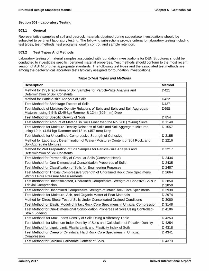
503.2 Test Types And Methods
Laboratory testing of material samples associated with foundation investigations for DEN Structures should be conducted to investigate specific, pertinent material properties. Test methods should conform to the most recent version of ASTM or other appropriate standards. The following test types and the associated test methods are among the geotechnical laboratory tests typically assigned for foundation investigations:
Table 1-Test Types and Methods
Description Method Method for Dry Preparation of Soil Samples for Particle-Size Analysis and Determination of Soil Constants
D421
Method for Particle-size Analysis of Soils D422 Test Method for Shrinkage Factors of Soils D427 Test Methods of Moisture-Density Relations of Soils and Soils and Soil-Aggregate Mixtures, using 5.5-lb (2.46-kg) Rammer & 12-in (305-mm) Drop
D698
Test Method for Specific Gravity of Soils D 854 Test Method for Amount of Material in Soils Finer then the No. 200 (75-um) Sieve D 1140 Test Methods for Moisture-Density Relations of Soils and Soil-Aggregate Mixtures, using 10-lb. (4.54-kg) Rammer and 18-in. (457-mm) Drop
D 1557
Test Methods for Unconfined Compressive Strength of Cohesive D 2155 Method for Laboratory Determination of Water (Moisture) Content of Soil Rock, and Soil-Aggregate Mixtures
D 2216
Method for Wet Preparation of Soil Samples for Particle-Size Analysis and Determination of Soil Constants
D 2217
Test Method for Permeability of Granular Soils (Constant Head) D 2434 Test Method for One-Dimensional Consolidation Properties of Soils D 2435 Test Method for Classification of Soils for Engineering Purposes D 2487 Test Method for Triaxial Compressive Strength of Undrained Rock Core Specimens Without Pore Pressure Measurements
D 2664
Test method for Unconsolidated, Undrained Compressive Strength of Cohesive Soils in Triaxial Compression
D 2850 D 2850
Test Method for Unconfined Compressive Strength of Intact Rock Core Specimens D 2938 Test Methods for Moisture, Ash, and Organic Matter of Peat Materials D 2974 Method for Direct Shear Test of Soils Under Consolidated Drained Conditions D 3080 Test Method for Elastic Moduli of Intact Rock Core Specimens in Uniaxial Compression D 3148 Test Method for One-Dimensional Consolidation Properties of Soils Using Controlled-Strain Loading
D 4186
Test Methods for Max. Index Density of Soils Using a Vibratory Table D 4253 Test Methods for Minimum Index Density of Soils and Calculation of Relative Density D 4254 Test Method for Liquid Limit, Plastic Limit, and Plasticity Index of Soils D 4318 Test Method for Creep of Cylindrical Hard Rock Core Specimens in Uniaxial Compression
D 4341
Test Method for Calcium Carbonate Content of Soils D 4373
Structural Design Standards Manual Chapter 5 - Geotechnical
January 2017 28 Denver International Airport
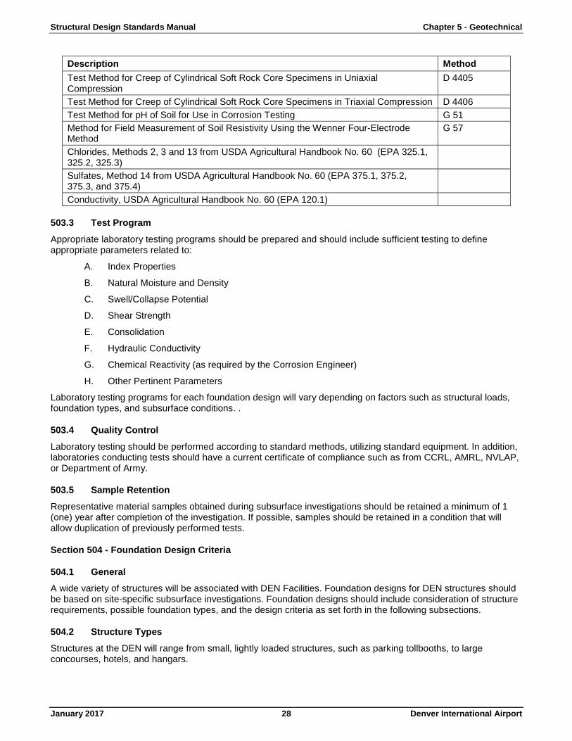
Description Method Test Method for Creep of Cylindrical Soft Rock Core Specimens in Uniaxial Compression
D 4405
Test Method for Creep of Cylindrical Soft Rock Core Specimens in Triaxial Compression D 4406 Test Method for pH of Soil for Use in Corrosion Testing G 51 Method for Field Measurement of Soil Resistivity Using the Wenner Four-Electrode Method
G 57
Chlorides, Methods 2, 3 and 13 from USDA Agricultural Handbook No. 60 (EPA 325.1, 325.2, 325.3)
Sulfates, Method 14 from USDA Agricultural Handbook No. 60 (EPA 375.1, 375.2, 375.3, and 375.4)
Conductivity, USDA Agricultural Handbook No. 60 (EPA 120.1)
503.3 Test Program
Appropriate laboratory testing programs should be prepared and should include sufficient testing to define appropriate parameters related to:
A. Index Properties
B. Natural Moisture and Density
C. Swell/Collapse Potential
D. Shear Strength
E. Consolidation
F. Hydraulic Conductivity
G. Chemical Reactivity (as required by the Corrosion Engineer)
H. Other Pertinent Parameters
Laboratory testing programs for each foundation design will vary depending on factors such as structural loads, foundation types, and subsurface conditions. .
503.4 Quality Control
Laboratory testing should be performed according to standard methods, utilizing standard equipment. In addition, laboratories conducting tests should have a current certificate of compliance such as from CCRL, AMRL, NVLAP, or Department of Army.
503.5 Sample Retention
Representative material samples obtained during subsurface investigations should be retained a minimum of 1 (one) year after completion of the investigation. If possible, samples should be retained in a condition that will allow duplication of previously performed tests.
Section 504 - Foundation Design Criteria
504.1 General
A wide variety of structures will be associated with DEN Facilities. Foundation designs for DEN structures should be based on site-specific subsurface investigations. Foundation designs should include consideration of structure requirements, possible foundation types, and the design criteria as set forth in the following subsections.
504.2 Structure Types
Structures at the DEN will range from small, lightly loaded structures, such as parking tollbooths, to large concourses, hotels, and hangars.
Structural Design Standards Manual Chapter 5 - Geotechnical
January 2017 29 Denver International Airport
In terms of foundation design, the principal distinction between structures is the magnitude of foundation loads and the method that these loads are transmitted to foundations. This information should be obtained from the Design Engineer and provide the basis for foundation design.
504.3 Foundation Types
A variety of foundation types will be appropriate for supporting structures associated with DEN facilities. Foundation types will include shallow foundations and deep foundations. Selection of appropriate foundation type must consider structural requirements, foundation loadings, subsurface conditions, foundation performance criteria, constructability, and economic feasibility. The following subsections should serve as a guideline in the selection of foundation types. Selection of specific structural foundations should be based on the results of site-specific subsurface investigations.
A. Shallow foundations
Shallow foundations include spread footings and post-tensioned mats. Shallow foundations transmit structural loads to competent soil or bedrock layers at shallow depths beneath the structure base. Competent layers will be located at shallow depths at many DEN locations.
An important limitation on the use of shallow foundations at the DEN site will be the swell potential of the supporting soils or weathered bedrock. Plans to utilize shallow foundations must include a demonstration that the proposed foundation system will support anticipated loads and limit settlement or heave to allowable levels. Proposed shallow foundations must also be constructible and economically feasible.
B. Deep foundations
Deep foundations such as driven piles and drilled piers (caissons) are used to transmit structural loads to competent soil or bedrock layers below the structure base. Loads may be supported by end bearing pressure, by side (skin) friction, or a combination of both. Piles may be driven, pre-drilled, or cast-in-place. Drilled piers (caissons) may be cast-in-place.
Plans to utilize deep foundations must include demonstrations that the proposed foundation system will support anticipated loads and limit settlement or heave to allowable levels. Deep foundations should also be constructible and economically feasible.
504.4 Design Criteria
Foundation designs should be developed for each structure based on site-specific foundation loadings and subsurface conditions. Selection of an appropriate foundation system should be based on the structure and its loadings, the nature and depth of bearing strata, overall site stability, comparative economics, and construction considerations.
Preliminary foundation designs and cost estimates may be based on standard engineering practices and the general recommendations in the following subsections.
A. Foundation loads
Foundation design loads shall be a combination of structural loads and geotechnical loads.
1. Structural Loads
Foundation loads shall be developed by the Design Engineer and shall include the unfactored dead loads and an appropriate combination of live and environmental loads. Typically foundations are designed for full dead load and at least 50 (fifty) percent of the live loads. Appropriate foundation loads should be calculated separately for each component of the foundation.
2. Geotechnical loads
Geotechnical loads should be estimated by the Geotechnical Engineer as the most severe combination of overburden, surcharge, uplift, downdrag, and lateral earth pressures. If groundwater is present, the geotechnical loads should consider the effective pressure loads plus hydrostatic loads and/or the total soil pressure loads. The Geotechnical Engineer should supply geotechnical loadings to the Design Engineer.
Structural Design Standards Manual Chapter 5 - Geotechnical
January 2017 30 Denver International Airport
B. Shallow foundations
Design of shallow foundations such as spread footings and mats should include consideration of bearing capacity, settlement, and resistance to lateral loads.
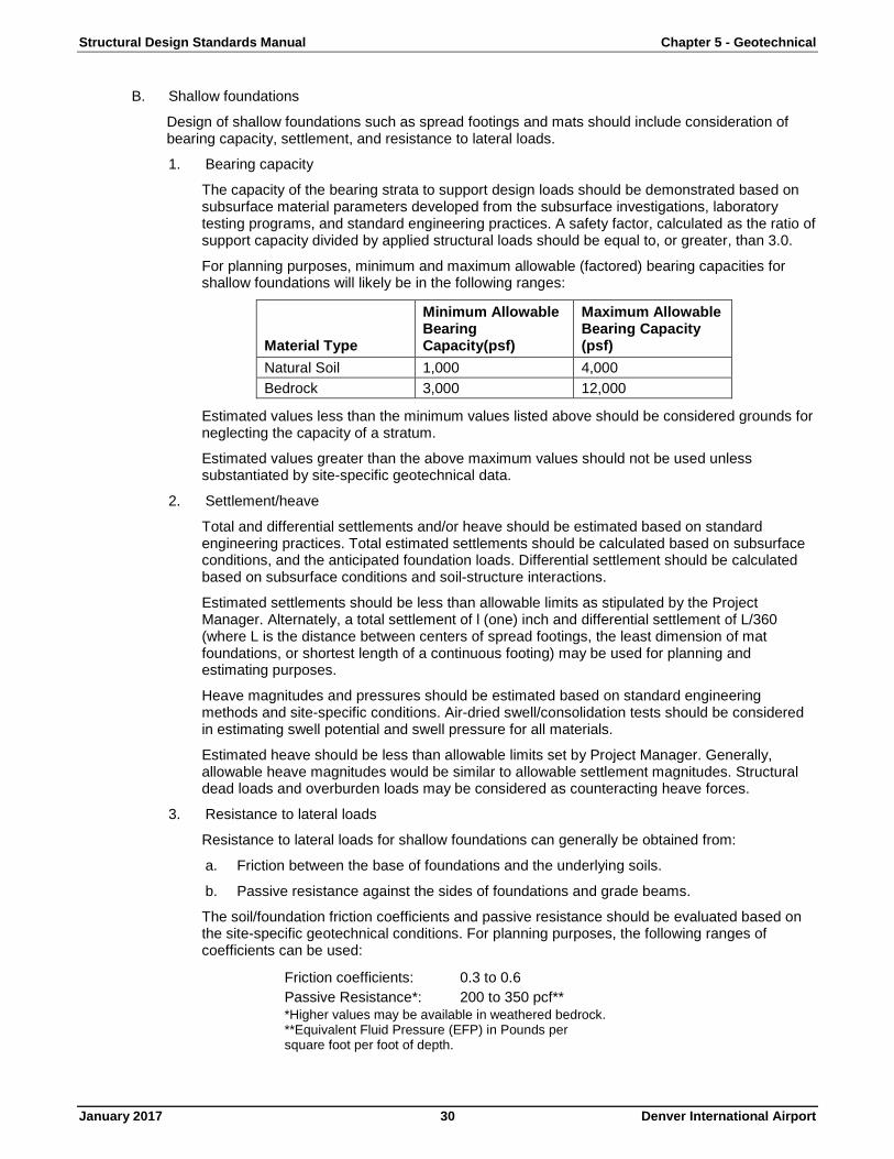
1. Bearing capacity
The capacity of the bearing strata to support design loads should be demonstrated based on subsurface material parameters developed from the subsurface investigations, laboratory testing programs, and standard engineering practices. A safety factor, calculated as the ratio of support capacity divided by applied structural loads should be equal to, or greater, than 3.0.
For planning purposes, minimum and maximum allowable (factored) bearing capacities for shallow foundations will likely be in the following ranges:
Material Type
Minimum Allowable Bearing Capacity(psf)
Maximum Allowable Bearing Capacity (psf)
Natural Soil 1,000 4,000 Bedrock 3,000 12,000
Estimated values less than the minimum values listed above should be considered grounds for neglecting the capacity of a stratum.
Estimated values greater than the above maximum values should not be used unless substantiated by site-specific geotechnical data.
2. Settlement/heave
Total and differential settlements and/or heave should be estimated based on standard engineering practices. Total estimated settlements should be calculated based on subsurface conditions, and the anticipated foundation loads. Differential settlement should be calculated based on subsurface conditions and soil-structure interactions.
Estimated settlements should be less than allowable limits as stipulated by the Project Manager. Alternately, a total settlement of l (one) inch and differential settlement of L/360 (where L is the distance between centers of spread footings, the least dimension of mat foundations, or shortest length of a continuous footing) may be used for planning and estimating purposes.
Heave magnitudes and pressures should be estimated based on standard engineering methods and site-specific conditions. Air-dried swell/consolidation tests should be considered in estimating swell potential and swell pressure for all materials.
Estimated heave should be less than allowable limits set by Project Manager. Generally, allowable heave magnitudes would be similar to allowable settlement magnitudes. Structural dead loads and overburden loads may be considered as counteracting heave forces.
3. Resistance to lateral loads
Resistance to lateral loads for shallow foundations can generally be obtained from:
a. Friction between the base of foundations and the underlying soils.
b. Passive resistance against the sides of foundations and grade beams.
The soil/foundation friction coefficients and passive resistance should be evaluated based on the site-specific geotechnical conditions. For planning purposes, the following ranges of coefficients can be used:
Friction coefficients: 0.3 to 0.6 Passive Resistance*: 200 to 350 pcf** *Higher values may be available in weathered bedrock. **Equivalent Fluid Pressure (EFP) in Pounds per square foot per foot of depth.
Structural Design Standards Manual Chapter 5 - Geotechnical
January 2017 31 Denver International Airport
Passive resistance should only be considered for soils permanently bearing against the foundation, and below depths of frost penetration.
C. Deep foundations
Design of deep foundations such as driven piles and drilled piers (caissons) should include consideration of support capacity, minimum dead lead, settlement (including elastic shortening), resistance to lateral loads, and foundation installation methods.
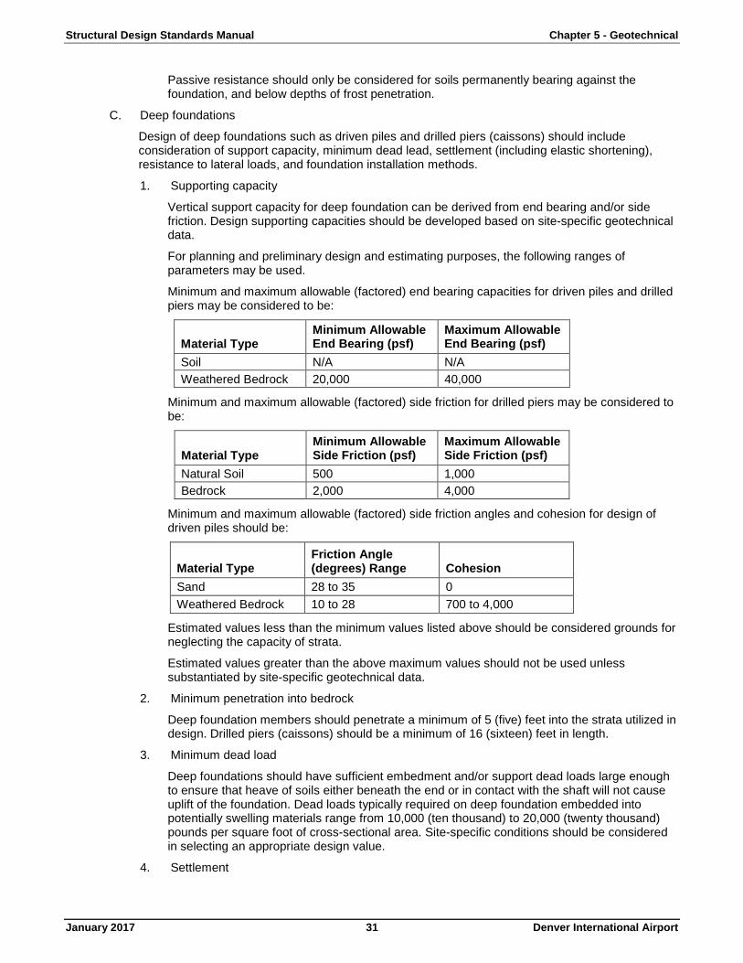
1. Supporting capacity
Vertical support capacity for deep foundation can be derived from end bearing and/or side friction. Design supporting capacities should be developed based on site-specific geotechnical data.
For planning and preliminary design and estimating purposes, the following ranges of parameters may be used.
Minimum and maximum allowable (factored) end bearing capacities for driven piles and drilled piers may be considered to be:
Material Type Minimum Allowable End Bearing (psf)
Maximum Allowable End Bearing (psf)
Soil N/A N/A Weathered Bedrock 20,000 40,000
Minimum and maximum allowable (factored) side friction for drilled piers may be considered to be:
Material Type Minimum Allowable Side Friction (psf)
Maximum Allowable Side Friction (psf)
Natural Soil 500 1,000 Bedrock 2,000 4,000
Minimum and maximum allowable (factored) side friction angles and cohesion for design of driven piles should be:
Material Type Friction Angle (degrees) Range Cohesion
Sand 28 to 35 0 Weathered Bedrock 10 to 28 700 to 4,000
Estimated values less than the minimum values listed above should be considered grounds for neglecting the capacity of strata.
Estimated values greater than the above maximum values should not be used unless substantiated by site-specific geotechnical data.
2. Minimum penetration into bedrock
Deep foundation members should penetrate a minimum of 5 (five) feet into the strata utilized in design. Drilled piers (caissons) should be a minimum of 16 (sixteen) feet in length.
3. Minimum dead load
Deep foundations should have sufficient embedment and/or support dead loads large enough to ensure that heave of soils either beneath the end or in contact with the shaft will not cause uplift of the foundation. Dead loads typically required on deep foundation embedded into potentially swelling materials range from 10,000 (ten thousand) to 20,000 (twenty thousand) pounds per square foot of cross-sectional area. Site-specific conditions should be considered in selecting an appropriate design value.
4. Settlement
Structural Design Standards Manual Chapter 5 - Geotechnical
January 2017 32 Denver International Airport
Settlement of deep foundations should be analyzed based on site-specific subsurface data and the structural properties of the deep foundation materials. For planning purposes for driven piles and drilled piers (caissons) designed and installed as described herein, settlements should be one-quarter inch, or less. The Design Engineer should add elastic compression of the pile/pier materials to the estimated geotechnical settlements.
5. Resistance to lateral loads
Lateral loads on deep foundations are generally associated with lateral structural loadings. Resistance of deep foundations to lateral loads is derived from lateral bearing of the foundation shaft on soils and/or weathered bedrock. Lateral load capacities of deep foundations should be estimated by use of p-y curves. Complete solutions for pile forces and deformations generally require computer simulations. For structures at the DEN site, a computer program should be used to model lateral loads on piles. The results of lateral load modeling should be reviewed by the Geotechnical Engineer.
6. Group action
For deep foundations to act as individual support members and realize their full capacity, the minimum center-to-center spacings must be at least 3 (three) times the shaft diameter. End bearing and side friction for groups of deep foundation members spaced closer may be reduced and the potential for settlements or heave may be increased.
Support capacity reductions and settlement/heave analyses should be performed for deep foundation groups not meeting the minimum spacing cited above.
7. Installation criteria
Deep foundations should meet specified vertical and horizontal installation tolerances.
Pile driving should include verification of pile stresses and capacities with Pile Driving Analyzers (PDA) (Reference 4). Exposed portions of driven piles should be inspected to verify they were not damaged during driving. Driven pile lengths should be modified during driving to account for actual subsurface conditions encountered.
Where caissons are to be installed beneath the groundwater table, specific dewatering and concrete placement methods must be specified by the Design Engineer. For example, casing may need to be set into the bedrock to cut off inflow. Alternatively, the piers should be large enough so that pumps can be installed to dewater the caisson hole immediately before concrete is placed. Concrete should be pumped into the bottom of the caisson. Under special conditions, as where caissons are to be installed through saturated sands, it may be necessary to use bentonite slurries to maintain open holes during drilling.
D. Subsurface perimeter drains
In potentially swelling soils, it is important to minimize changes in moisture content in soils beneath and adjacent to foundations. One method that can be beneficial is a properly installed and functioning subsurface perimeter drain.
The potential exists for perched groundwater table development. Additional lateral drains may be required in large and/or deep structures where the distance between subsurface perimeter drains may not be adequate for effective drainage. In addition, utility lines can transmit water below structure. The use of impervious collars on utility lines should be considered to minimize transmission of groundwater into structural areas.
Design and installation of subsurface perimeter drains should include consideration of at least the following:
1. Locations
Subsurface perimeter drains should be considered around the periphery of all structures unless the Subsurface Investigation report specifically says drains are not required.
Structural Design Standards Manual Chapter 5 - Geotechnical
January 2017 33 Denver International Airport
2. Installation requirements
Subsurface perimeter drains should be constructed with HDPE drainpipe, perforated PVC, or equivalent. The drain should be sized to transmit expected inflows, but in no case be smaller than 4 (four) inches in diameter. Perforations should be sufficient to accept the expected inflow, but should not exceed l/4 inch diameter and should not be less than l (one) square inch per lineal foot of drainpipe.
The drain pipes should be installed in gravel filled trenches, approximately 3 (three) times the drainpipe diameter in width. To avoid clogging of the drain by fine-grained soils, the gravel encapsulating the pipe should be wrapped in drain geofabric.
Perimeter drains should be below the base of the lowest foundation level. Drain spacing and depth should be sufficient to maintain the cone of depression below the depth of facilities to be protected. Drains should slope uniformly and positively with a slope of at least l (one) percent. The base of the drain excavation should also slope uniformly in the direction of the drain slope.
3. Discharge
All perimeter drains should discharge to a positive, frost-free outlet such as a frost-free gravity draining outfall and/or sump system. Preferably, the sumps should be inside the structure, for frost protection and ease of maintenance. Sumps should be equipped with pumps, or prepared for future pump installation in the event that water enters and rises in the sump.
In cases where sump failure could lead to flooding of floor areas, a back-up sump and an alarm system should be included in the design and construction of the subsurface perimeter drain system.
Section 505 - Slabs At Grade
505.1 General
Floor systems for the lowest levels of buildings and parking structures are generally constructed with concrete slabs. Ideally, these slabs are placed directly on underlying stable soils. In areas where the subgrade soils exhibit swell potential, special design considerations must be incorporated to prevent excessive heave, distortion, and/or cracking of the slab. The following slab design alternatives and design criteria should be considered for design of all lower level slabs.
505.2 Slab Design Alternatives
A. Slab-on-grade
A concrete slab placed directly on natural subgrade soils represents the simplest form of slab construction. Slab-on-grade construction is appropriate when subgrade soils exhibit adequate strength and have "none" or "low" swell potential. Slabs-on-grade should be separated from surrounding structural members. Adequate subgrade drainage is required.
B. Slab-on-fill
A concrete slab may be placed directly on structural fill. Slab on fill construction is appropriate where non-swell potential (NSP) fill is used to replace inadequate soils, or the slab elevation is higher than existing ground surface elevations. Fill used to replace inadequate soils should be thick enough to replace or overcome natural soil inadequacies. In the case of swelling soils, this thickness should be adequate to replace the swelling layer or provide enough surcharge to limit heave due to swell. Fill beneath slabs should be compacted to specified criteria and adequately drained. Generally, it is impractical to consider replacement fills thicker than about 6 (six) feet. Where replacement fills thicker (six) feet are indicated, it is usually more economical to consider structural slabs.
C. Structural slabs (slab on void)
Structural slab systems may be utilized which isolate slabs from subgrade soils and transfer floor loads to surrounding structural members. A structural slab system is appropriate when subgrade soil properties have swelling soils, or are inadequate to support the slab and the inadequate soil cannot be sufficiently improved or replaced. In the case of swelling subgrade soils, adequate void space
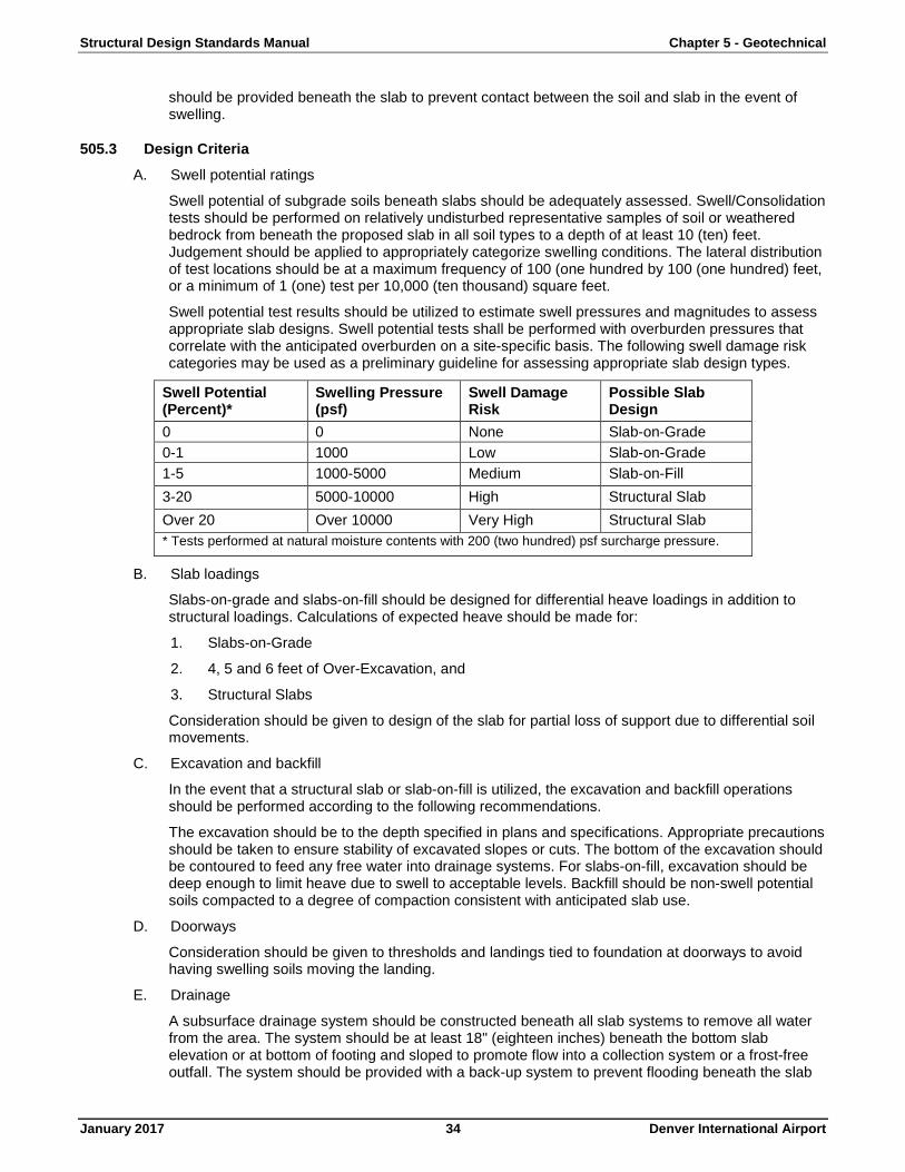
Structural Design Standards Manual Chapter 5 - Geotechnical
January 2017 34 Denver International Airport
should be provided beneath the slab to prevent contact between the soil and slab in the event of swelling.
505.3 Design Criteria
A. Swell potential ratings
Swell potential of subgrade soils beneath slabs should be adequately assessed. Swell/Consolidation tests should be performed on relatively undisturbed representative samples of soil or weathered bedrock from beneath the proposed slab in all soil types to a depth of at least 10 (ten) feet. Judgement should be applied to appropriately categorize swelling conditions. The lateral distribution of test locations should be at a maximum frequency of 100 (one hundred by 100 (one hundred) feet, or a minimum of 1 (one) test per 10,000 (ten thousand) square feet.
Swell potential test results should be utilized to estimate swell pressures and magnitudes to assess appropriate slab designs. Swell potential tests shall be performed with overburden pressures that correlate with the anticipated overburden on a site-specific basis. The following swell damage risk categories may be used as a preliminary guideline for assessing appropriate slab design types.
Swell Potential (Percent)*
Swelling Pressure (psf)
Swell Damage Risk
Possible Slab Design
0 0 None Slab-on-Grade 0-1 1000 Low Slab-on-Grade 1-5 1000-5000 Medium Slab-on-Fill 3-20 5000-10000 High Structural Slab Over 20 Over 10000 Very High Structural Slab * Tests performed at natural moisture contents with 200 (two hundred) psf surcharge pressure.
B. Slab loadings
Slabs-on-grade and slabs-on-fill should be designed for differential heave loadings in addition to structural loadings. Calculations of expected heave should be made for:
1. Slabs-on-Grade
2. 4, 5 and 6 feet of Over-Excavation, and
3. Structural Slabs
Consideration should be given to design of the slab for partial loss of support due to differential soil movements.
C. Excavation and backfill
In the event that a structural slab or slab-on-fill is utilized, the excavation and backfill operations should be performed according to the following recommendations.
The excavation should be to the depth specified in plans and specifications. Appropriate precautions should be taken to ensure stability of excavated slopes or cuts. The bottom of the excavation should be contoured to feed any free water into drainage systems. For slabs-on-fill, excavation should be deep enough to limit heave due to swell to acceptable levels. Backfill should be non-swell potential soils compacted to a degree of compaction consistent with anticipated slab use.
D. Doorways
Consideration should be given to thresholds and landings tied to foundation at doorways to avoid having swelling soils moving the landing.
E. Drainage
A subsurface drainage system should be constructed beneath all slab systems to remove all water from the area. The system should be at least 18" (eighteen inches) beneath the bottom slab elevation or at bottom of footing and sloped to promote flow into a collection system or a frost-free outfall. The system should be provided with a back-up system to prevent flooding beneath the slab
Structural Design Standards Manual Chapter 5 - Geotechnical
January 2017 35 Denver International Airport
in case of subsurface drainage system failure. The subsurface drainage may be a subsurface perimeter drain.
Section 506 - Lateral Earth Pressure Design Criteria
506.1 General
Lateral earth pressures will be exerted on retaining walls, basement walls, culverts, shoring, and other members supporting earth materials. These earth retaining structures must be designed to resist the forces imposed by the supported soil and groundwater.
506.2 Earth Retaining Structure Types
A. Rigid
Structural elements that resist earth pressures by their internal structural strength as rigid bodies and transmit the loads to foundations or other bearing elements with minimal elastic structural deformations are known as rigid type earth retaining structures. Rigid retaining structures may or may not yield, but do not deform. Typical rigid retaining structures include basement walls, reinforced concrete retaining walls, grade beams, wing walls, etc. Temporary bracing of normally "flexible" material (for example, steel with wood lagging) may act as rigid elements if constructed with sufficient restraints.
B. Flexible
Flexible earth retaining structures include sheet pile bulkheads, shoring, and other support elements that may deform as they restrain imposed loads. At the DEN, flexible bulkheads will likely be temporary being utilized only during the construction period.
Flexible supports differ from rigid earth retaining structures in that they can yield within acceptable limits to accommodate the forces imposed on them. Flexible systems include both free standing and tied-back soldier piles and lagging, sheet piles, etc.
506.3 DESIGN CRITERIA
A. Loads
1. Lateral earth pressure
Lateral earth pressure is the pressure exerted by earth material against a structure. The magnitude of the earth pressure is determined by the physical properties of the earth materials, and the amount and direction of structure and earth displacements (Reference 5).
The three general conditions of displacement often considered in design of earth retaining structures are the active, passive and at-rest conditions, and are defined as follows:
a. The active case results when the restraint moves away from the supported earth. An example of active pressure would be against a cantilever retaining wall.
b. The passive case results when a structural element moves towards the restrained earth. An example would be where a footing or grade beam is used to resist lateral loads imposed on a structure.
c. The at-rest case occurs where there is no relative movement between earth and the restraint. Such a condition may occur against a stiff, unyielding wall, such as a deep basement wall.
To select the design lateral earth pressure, the Design Engineer will need to evaluate whether the active, at-rest or passive condition (or some intermediate condition) applies. Earth pressure data can then be developed considering the physical properties of the earth material.
Generally, the earth materials are subdivided into two groups, cohesionless (sandy) and cohesive (clayey). Two general theories used to evaluate lateral earth pressure coefficients for cohesionless and cohesive soils are the Coulomb and Rankin methods, which are described in soil mechanics textbooks (Reference 6). .
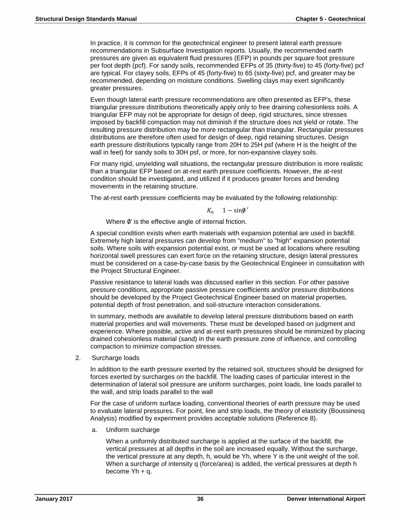
Structural Design Standards Manual Chapter 5 - Geotechnical
January 2017 36 Denver International Airport
In practice, it is common for the geotechnical engineer to present lateral earth pressure recommendations in Subsurface Investigation reports. Usually, the recommended earth pressures are given as equivalent fluid pressures (EFP) in pounds per square foot pressure per foot depth (pcf). For sandy soils, recommended EFPs of 35 (thirty-five) to 45 (forty-five) pcf are typical. For clayey soils, EFPs of 45 (forty-five) to 65 (sixty-five) pcf, and greater may be recommended, depending on moisture conditions. Swelling clays may exert significantly greater pressures.
Even though lateral earth pressure recommendations are often presented as EFP's, these triangular pressure distributions theoretically apply only to free draining cohesionless soils. A triangular EFP may not be appropriate for design of deep, rigid structures, since stresses imposed by backfill compaction may not diminish if the structure does not yield or rotate. The resulting pressure distribution may be more rectangular than triangular. Rectangular pressures distributions are therefore often used for design of deep, rigid retaining structures. Design earth pressure distributions typically range from 20H to 25H psf (where H is the height of the wall in feet) for sandy soils to 30H psf, or more, for non-expansive clayey soils.
For many rigid, unyielding wall situations, the rectangular pressure distribution is more realistic than a triangular EFP based on at-rest earth pressure coefficients. However, the at-rest condition should be investigated, and utilized if it produces greater forces and bending movements in the retaining structure.
The at-rest earth pressure coefficients may be evaluated by the following relationship:
𝐾𝐾0 = 1 − sin0/ ′
Where 0/ ' is the effective angle of internal friction.
A special condition exists when earth materials with expansion potential are used in backfill. Extremely high lateral pressures can develop from "medium" to "high" expansion potential soils. Where soils with expansion potential exist, or must be used at locations where resulting horizontal swell pressures can exert force on the retaining structure, design lateral pressures must be considered on a case-by-case basis by the Geotechnical Engineer in consultation with the Project Structural Engineer.
Passive resistance to lateral loads was discussed earlier in this section. For other passive pressure conditions, appropriate passive pressure coefficients and/or pressure distributions should be developed by the Project Geotechnical Engineer based on material properties, potential depth of frost penetration, and soil-structure interaction considerations.
In summary, methods are available to develop lateral pressure distributions based on earth material properties and wall movements. These must be developed based on judgment and experience. Where possible, active and at-rest earth pressures should be minimized by placing drained cohesionless material (sand) in the earth pressure zone of influence, and controlling compaction to minimize compaction stresses.
2. Surcharge loads
In addition to the earth pressure exerted by the retained soil, structures should be designed for forces exerted by surcharges on the backfill. The loading cases of particular interest in the determination of lateral soil pressure are uniform surcharges, point loads, line loads parallel to the wall, and strip loads parallel to the wall
For the case of uniform surface loading, conventional theories of earth pressure may be used to evaluate lateral pressures. For point, line and strip loads, the theory of elasticity (Boussinesq Analysis) modified by experiment provides acceptable solutions (Reference 8).
a. Uniform surcharge
When a uniformly distributed surcharge is applied at the surface of the backfill, the vertical pressures at all depths in the soil are increased equally. Without the surcharge, the vertical pressure at any depth, h, would be Yh, where Y is the unit weight of the soil. When a surcharge of intensity q (force/area) is added, the vertical pressures at depth h become Yh + q.
Structural Design Standards Manual Chapter 5 - Geotechnical
January 2017 37 Denver International Airport
The lateral pressure, σH, due to the uniform surcharge q, is equal to Kg.
The K value is either the active co-efficient, Ka, the at-rest coefficient, Ko, or the passive coefficient, Kp, depending upon whether the wall tends to move away from, or toward, the surcharge area. The uniform lateral pressure due to the surcharge is then added to the lateral earth pressures.
b. Point loads
The lateral pressure distribution on a vertical line on the retaining structure closest to a point load may be calculated. Away from the line closest to the point load, the lateral stress decreases.
c. Line loads
Continuous wall footings of narrow width, or similar loads, parallel to a retaining structure may be taken as line loads. For this case, the lateral pressure increases from zero at the ground surface, to a maximum value at a given depth, and gradually diminishes at greater depths. The lateral pressure distribution on a vertical plane parallel to a line load may be calculated.
d. Strip loads
Wider wall footings or other similar loads parallel to a retaining structure may be taken as strip loads. The lateral pressure distribution on the wall may be calculated.
3. Hydrostatic loads
Where retaining structures support an unbalance in hydrostatic water levels, such as where a water level exists in the backfill but not in front of the wall, the hydrostatic pressures must be carried by the wall. Hydrostatic pressures are equal to an equivalent fluid pressure of Ywh, where Yw is the unit weight of water, and h is the depth below the water level.
Below the hydrostatic water level, lateral earth pressures should be evaluated based on the buoyant weight of the earth material.
Because the hydrostatic loading condition is ordinarily more severe than the drained loading condition, it is desirable to prevent hydrostatic water levels in wall backfill. For basement walls and retaining walls, this can be accomplished by using free draining backfill material with proper subsurface drainage to carry water away from the base of the fill. Alternate methods including geodrains and geofabrics may also be considered.
Subsurface drainage may be accomplished by properly designed weep holes through retaining walls, or lateral drains at the base of basement walls leading to a positive outlet.
B. Resistance to overturning
Retaining structures must be supported so as not to turn over under the earth pressure and surcharge loads. Basement and other structure walls are typically restrained by the structure. Freestanding walls need to be analyzed so the restraining moments are at least 1.5 times greater than the activating moments.
C. Resistance to sliding
Retaining structures must be able to resist the horizontal thrust of the earth pressures and other loads. This can be done structurally for basement walls. For free standing walls, the sum of the available friction on the base of the wall and passive resistance at the toe of the wall must be at least 1.5 times the activating loads. Shear keys on the base of foundations often assist in resisting sliding forces.
D. Structural requirements
Earth retaining structures must be designated to resist the imposed loads in accordance with the Building Code and other structural requirements.
Structural Design Standards Manual Chapter 5 - Geotechnical
January 2017 38 Denver International Airport
Section 507 - Excavation Stability Design Criteria
507.1 General
Excavations at the DEN site may be either permanent or temporary, and braced or unbraced. In planning excavations, consideration must be given to the stability of the sides of the excavation. All excavations in which men will work must be braced, sloped back, or otherwise engineered to meet all the requirements of OSHA and all other regulatory agencies with jurisdiction over the project.
507.2 Excavation Types
A. Braced
When excavations extend into soil that will not stand stable at the required inclination, the sides of the excavation are usually braced. Narrow excavations are typically braced by struts that support one side of the excavation against the other. The struts hold sheeting, lagging, sheet piles, H-piles, etc. in-place against the face of the excavations. Where excavations are not narrow, the bracing may be by the structural strength of the bracing, as in sheet piles or soldier piles extending into the subgrade below the excavation, by tiebacks into the supported soil, or rakers extending into the excavation.
B. Unbraced
Where excavations extend into competent materials, such as the weathered bedrock at the DEN site, excavations may not need to be braced. The need for bracing depends on the depth and duration of the excavation, and the strength and jointing of the weathered bedrock. It may be possible to construct fairly deep unbraced excavations into weathered bedrock for periods of time typically associated with structure construction activities.
C. Sloped
Where bracing is not appropriate or economical, the sides of an excavation may be sloped to a stable inclination. At a minimum, the slopes should meet OSHA and other regulatory agency requirements. The sides of sloped excavations should be analyzed using slope stability analysis procedures so that the sum of the forces and moments resisting movement should be at least 1.5 times the sum of the forces and moments tending to produce movement.
507.3 Design Criteria
A. Lateral loads
Lateral loads on braced excavations will be the result of lateral earth pressures, surcharge, and hydrostatic loads.
B. Bracing
The bracing that transmits compressional forces from one side of the excavation to the other should be structurally designed to carry the earth pressure and other loads. Where expansive soils are to be retained, the Geotechnical Engineer should evaluate if additional earth pressures should be included in the design, or specify replacement backfill material.
Section 508 - Groundwater Control Criteria
508.1 General
Control of groundwater will be a very important aspect of design and construction of structures at the DEN site, especially for locations underlain by potentially expansive soils and bedrock. The extent of groundwater control will depend on the depth of proposed excavations, the materials into which the excavations will extend, and the site-specific geohydrology. At a minimum, all structures should have subsurface perimeter drains.
508.2 Groundwater Occurrence
Based on the data presented in the AAE Preliminary Report (Reference 1), local perched groundwater tables may exist naturally at the DEN site. However, at most locations within the DEN site, there is the possibility of the
Structural Design Standards Manual Chapter 5 - Geotechnical
January 2017 39 Denver International Airport
development of locally perched groundwater tables, as site development proceeds. This is because at most locations permeability deceases with depth until essentially impervious bedrock is encountered. Thus, water infiltrating into the ground from the surface, landscaped areas, leaking pipes, etc. will tend to migrate downward to the impervious bedrock layers and then mound up or dissipate laterally. At many structure locations, the required excavations will extend into low permeability material such as clay or weathered bedrock. Thus, as water seeps into the ground it may be trapped in the "bath tub" in which the structure is set. In addition, groundwater may be transmitted by sand and sandstone layers, and by subsurface soils in old drainageways.
Where existing drainages cross the site, there may be shallow groundwater tables within the flood plain soils. Preparation of such sites for structure construction should include provisions for surface and subsurface drainage to make the location suitable for the proposed construction.
508.3 Construction Dewatering
A. Infiltration rate
At those locations where naturally occurring perched groundwater is encountered during construction, the infiltration rate should be estimated by the Design Engineer based on site-specific subsurface conditions. It is anticipated that most naturally occurring groundwater will be contained within and just above the surface of weathered claystone and sandstone bedrock. Within weathered claystone, the groundwater will be in joints and fractures. High infiltration rates would not be expected. In weathered sandstone, locally high infiltration could occur upon initial excavation. It is expected that in both weathered claystone and weathered sandstone, the infiltration rates will diminish with time to relatively low base rates as construction progresses.
Where excavations extend into alluvial materials in drainages, infiltration rates should be estimated based on the site-specific geohydrology.
B. Dewatering techniques
There are many dewatering techniques available depending on the depth and geometry of the excavation and site geohydrological conditions. Dewatering techniques include such methods as deep wells and well points. However, given the site conditions prevalent at the DEN site, it is anticipated that simple ditch and sump type dewatering will be sufficient at most structure locations. This should be defined for each excavation by the Design Engineer.
The ditch and sump dewatering method consists of digging a collector ditch around the perimeter of the excavation, sloped to sump(s) from where the collected inflow is pumped from the excavation. If an open ditch is inconvenient, a geotextile lined gravel drain can be installed to carry water to the sumps.
Other simple techniques include trenches outside the excavation limits that extend to depths below the excavation limit, or into impervious weathered bedrock.
C. Water disposition
Water obtained from dewatering systems should be discharged into the site surface drainage system. Water from dewatering operations could be discharged to the storm sewer system.
D. Colorado Department of Health (CDOH)
All dewatering system discharge water shall meet the water quality standards of the CDOH, DEN Environmental, and all appropriate permits obtained before discharge to the site surface water system.
508.4 Long Term Control
A. Applications
Groundwater control should be considered for:
1. All structures extending below final exterior grades and/or below hydrostatic water levels.
2. Deep permanent excavations, including all excavations extending within 4 (four) feet of weathered bedrock elevation.
Structural Design Standards Manual Chapter 5 - Geotechnical
January 2017 40 Denver International Airport
3. Slopes cut into native subsurface materials.
4. Other locations where undesirable groundwater seepage may occur.
The purpose of long-term control of groundwater is to:
1. Maintain hydrostatic levels below the bottoms of basements, occupied space, excavations, etc.
2. Control groundwater that emerges on cut slopes, or prevent groundwater from emerging on cut slopes.
B. Infiltration rate
Design infiltration rates should be established on a structure or site-specific basis by the Design Engineer. For planning and cost estimating purposes only, based ont he general site specific data presented by AAE (Reference 1), it is expected that infiltration rates for most long term groundwater control systems will be low, probably as the order of 10 (ten) gpm or less for structures and 50 (fifty) to 120 (one hundred twenty) gpm or less for large slopes and other deep excavations, except for excavations into alluvial aquifers.
C. Typical drain sections
Drain sections will vary depending on the purpose and location of the drain and the type of structure/slope to be protected.
The following general principles apply to design of typical drain sections.
1. The drain must be deep enough to maintain the hydrostatic levels at or below design levels. That is, the drain depths must be sufficient to keep the groundwater "mound" between the drains below design levels.
2. Where there are no anticipated or potential permanent hydrostatic levels, but rather where intermittent perched water or other seepage may develop, the drain should extend through the zone of seepage to a depth sufficient to maintain potential hydrostatic levels below design levels.
3. The drain must slope continuously and positively to an outlet. Minimum drain slopes would typically be l (one) percent, unless the Design engineer demonstrates the effectiveness of drains with lesser slopes.
4. The base of the drain excavations should slope continuously and positively to an outlet with a minimum slope of l (one) percent, as described for the drain in Step 3, above.
5. The drainpipe should be sized to carry the maximum expected flow, with a factor of safety of 1.2 for less than 100 (one hundred) gpm and 1.5 for flows in excess of 100 (one hundred) pgm, but should be a minimum of 4 (four) inches in diameter.
6. The drainpipe should be embedded in washed drain rock (filter material per the applicable CDOH Standard Specification) that is encased in geofabric, or equivalent drain section, that will transmit water to the drain without transporting fines or other subsurface materials.
7. The drain must discharge to a positive outfall that does not freeze and has a capacity to accept the design inflow without backup.
D. Outfall
Drains that constitute portions of long-term groundwater control should discharge to positive, frost free outfalls. Outfalls may be gravity discharges to a surface water course, sumps in which discharge pumps may be placed, gravel drains, storm or sanitary sewers (if allowed by the sewer authority), etc.
A note of caution with respect to gravel drains, the Design Engineer must demonstrate that the drain has sufficient cross-sectional area to transmit the design flow with an appropriate factor of safety, and that the drain has a positive discharge.
Structural Design Standards Manual Chapter 5 - Geotechnical
January 2017 41 Denver International Airport
Sump-pump discharges to a surface drainage shall extend at least 10 (ten) feet away from the structure and discharge to a swale with sufficient capacity to carry the flow. The outlet area must be armored against erosion due to the discharge velocity.
Other outfall details should be developed by the Design Engineer as needed to develop a properly designed and engineered facility.
Section 509 - Protection of Adjacent Structures
509.1 General
When proposed facilities are to be constructed adjacent to existing DEN facilities, steps should be taken to protect the existing facilities from excessive vibrations or displacements. The Design Engineer should assure that construction documents contain specific methods or performance standards for protection to adjacent structures.
509.2 Vibration
A. Occurrence
Impact energy from construction operations may produce vibrations on adjacent structures. The level of vibrations is a function of the impact energy, the distance from the impact to the existing facility, and the dynamic stress strain characteristics of the intervening soils. The level of vibration that an existing facility can accept depends on the type of structure and the structure use. Vibration effects are most critical when the existing facility contains vibration sensitive equipment such as computers, switchgear, etc. With respect to people occupying or working in the building, people in quiet office space will be disturbed more by vibrations than people in hallways, reception areas, etc.
Experience indicates that high energy construction procedures such as pile driving, ripper excavation and light blasting may produce problem vibrations.
It is assumed that all DEN structures will conform to current building codes and will be designed for the current Denver Building Code Seismic addendum.
B. Protection
In order to maintain vibrations within acceptable limits, strict limitations should be placed on high energy impact construction activities. For example, blasting should be closely regulated adjacent to existing structures. In addition, drilled piers should be considered in lieu of driven piles.
For planning purposes, it may be considered that to minimize the potential for damage, vibrations due to construction activity should be limited 1.0 in/sec at existing facilities. If the facility is occupied, construction activity should be performed to keep peak particle velocities at 0.5 in/sec or less. However, some facilities may have more stringent criteria. Acceptable vibration levels should be established on a structure specific basis by the Design Engineer. These studies should include preconstruction surveys of ambient vibration levels. In areas of critical concern, vibration monitoring should be conducted during the vibration-producing construction activities.
509.3 Excavation
A. Occurrence
Where construction of proposed facilities will require excavation adjacent to existing DEN structures, the existing facility may need to be protected against movements into the excavation. The effect on the existing facility will depend primarily on the geometry of the proposed excavation, and the type of foundation and floor slab system in the existing facility.
B. Protection
The best protection for existing structures is to plan proposed excavations so that existing floor slabs and foundations will be outside the zone of influence of the excavation. Where excavations must be performed within the zone of influence, existing foundations should be supported by underpinning or bracing as required to prevent unacceptable movements. Underpinning must be planned on a case-by-case basis by the Design Engineer.
Structural Design Standards Manual Chapter 5 - Geotechnical
January 2017 42 Denver International Airport
To document the potential for actual damage due to excavation, a detailed pre-excavation survey should be performed on the condition of the existing structure, noting all cracks, displacements, etc.
Section 510 - Field Instrumentation
510.1 General
Field instrumentation should be installed and monitored as necessary to develop foundation design parameters and evaluate foundation performance. The need for field instrumentation should be evaluated on a structure-by-structure basis by the Design Engineer. Field instrumentation, such as simple piezometers, is routinely installed to measure groundwater levels. High quality monitoring wells should be installed if groundwater contamination is known or suspected.
Settlement monitoring is typically not performed at normal structure foundation locations. However, it may be considered where there are unusual or exceptionally large foundation loads, or where foundations are adjacent to the zone of influence of an adjacent excavation.
510.2 Groundwater
A. Monitoring requirements
As previously noted, except in alluvial aquifers in drainages, groundwater at the DEN site is typically expected to exist as local perched groundwater tables. To assess the presence of groundwater on the zone affected by the proposed construction, groundwater levels should be evaluated as a part of all structure subsurface investigations. Groundwater levels should be noted in each boring at the time of drilling, and at later dates so that stabilized water levels can be evaluated. Simple standpipe piezometers should be installed in representative borings so that longer term groundwater measurements can be made.
A condition that may be encountered at the DEN site is localized confined aquifers. These may exist, for example, in weathered sandstone layers confined between weathered claystone beds. The water levels in the sandstone layer may be under artesian conditions. Where subsurface conditions encountered in borings suggest the presence of these locally confined groundwater zones, installation of sealed piezometers should be considered.
Where groundwater contamination is known or suspected monitoring wells should be installed to evaluate the nature and extent of the contamination. The monitor well locations should be selected based on a site geohydrologic investigation.
B. Monitoring techniques
As indicated above, the most basic type of ground water monitoring is to observe groundwater levels in open boreholes. Groundwater encountered during drilling should be noted on the boring logs, along with other observations that may indicate groundwater, such as very wet materials, water seeping into the boring, etc. Water levels should be measured in open boreholes 24 (twenty-four) hours after completion of drilling, and up to 7 (seven) days after drilling, or until groundwater levels stabilize.
Simple piezometers may be constructed by installing slotted PVC pipe, or other similar materials, into open boreholes. The PVC pipe should be backfilled with properly graded sand to a depth above the static groundwater level. Groundwater levels should be observed 24 (twenty-four) hours after installation, and periodically thereafter, as necessary to evaluate stabilized and/or changing ground water levels.
Where groundwater levels are to be measured in isolated portions of boreholes, sealed piezometers should be installed. Groundwater levels in sealed piezometers should be monitored as necessary to establish stabilized and/or changing water levels.
All piezometer standpipes, both sealed and unsealed, should be numbered and clearly identified in the field.
Monitoring wells installed to monitor groundwater contamination should be designed by the Design Engineer and comply with applicable EPA, Colorado Department of Health (CDOH) and other regulatory agency requirements. As groundwater characterization is usually a requirement of such
Structural Design Standards Manual Chapter 5 - Geotechnical
January 2017 43 Denver International Airport
groundwater studies, monitor wells should be of sufficient diameter (normally 4 inches minimum) so that water samples can be obtained.
C. Reporting
Groundwater data obtained during Subsurface Investigations should be reported in the subsurface investigation reports. Borehole groundwater data should be included in the boring logs. Piezometer data should be tabulated on tables indicating groundwater depths/elevations with dates of observations. Groundwater levels can also be presented graphically.
Groundwater data from monitoring wells should be presented in Geohydrological Reports to meet current EPA or CDOH reporting requirements.
510.3 Settlement/Heave
A. Monitoring requirements
As noted earlier, it is appropriate to monitor foundation settlement/heave at unusual or exceptionally heavily loaded foundations, or at foundations within or adjacent to the zone of influence of adjacent excavations. It may also be appropriate to monitor movement of slabs-on-grade supported on potentially expansive materials.
B. Monitoring techniques
The simplest form of settlement/heave monitoring is to establish survey monuments on the foundation/floor slabs of interest. To facilitate future monitoring programs it is very important to obtain elevations on the top of all as built foundations.
C. Reporting
Settlement/heave monitoring data should be reported as elevation survey data by the dates observed.
End of Chapter
Structural Design Standards Manual Appendix A - Abbreviations
January 2017 44 Denver International Airport
Appendix A - Abbreviations
AAE AA Engineers and Associates, Inc. AASHTO American Association of State Highway and Transportation Officials AMRL AASHTO Materials Reference Laboratory ASCE American Society of Civil Engineers ASTM American Society for Testing and Materials CCRL Cement and Concrete Reference Laboratory CDOH Colorado Department of Highways DEN Denver International Airport EFP Equivalent Fluid Pressure EPA Environmental Protection Agency F Bracing Strut Loads FSB Factor of Safety Against Bottom Instability H Depth Below Ground Surface H Height of Retaining Structure HDPE High Density Polyethylene K Lateral Earth Pressure Coefficient Ka Active Earth Pressure Coefficient Ko At-rest Earth Pressure Coefficient Kp Passive Earth Pressure Coefficient l Excavation Strut Spacing L Distance between Centers of Spread Footings, the Least Dimension of
Mat Foundations, or Shortest Length of a Continuous Footing m Horizontal Distance Coefficient n Vertical Depth Coefficient No Cohesive Soil Strength Coefficient NSP Non-Swell Potential NVLAP National Voluntary Laboratory Accreditation Program OSHA Occupational Health and Safety Administration pcf Pounds Per Square Foot Per Foot Depth PDA Pile Driving Analyzer PH Resultant Horizontal Earth Pressure psf Pounds Per Square Foot PVC Polyvinyl Chloride P-Y Load Versus Deflection, as used in Pile Lateral Load Modeling q Surcharge or Areal Load Pressure Intensity Q1 Line Load Intensity Qp Point Load Intensity R Distance from Blast Point SCS Soil Conservation Service
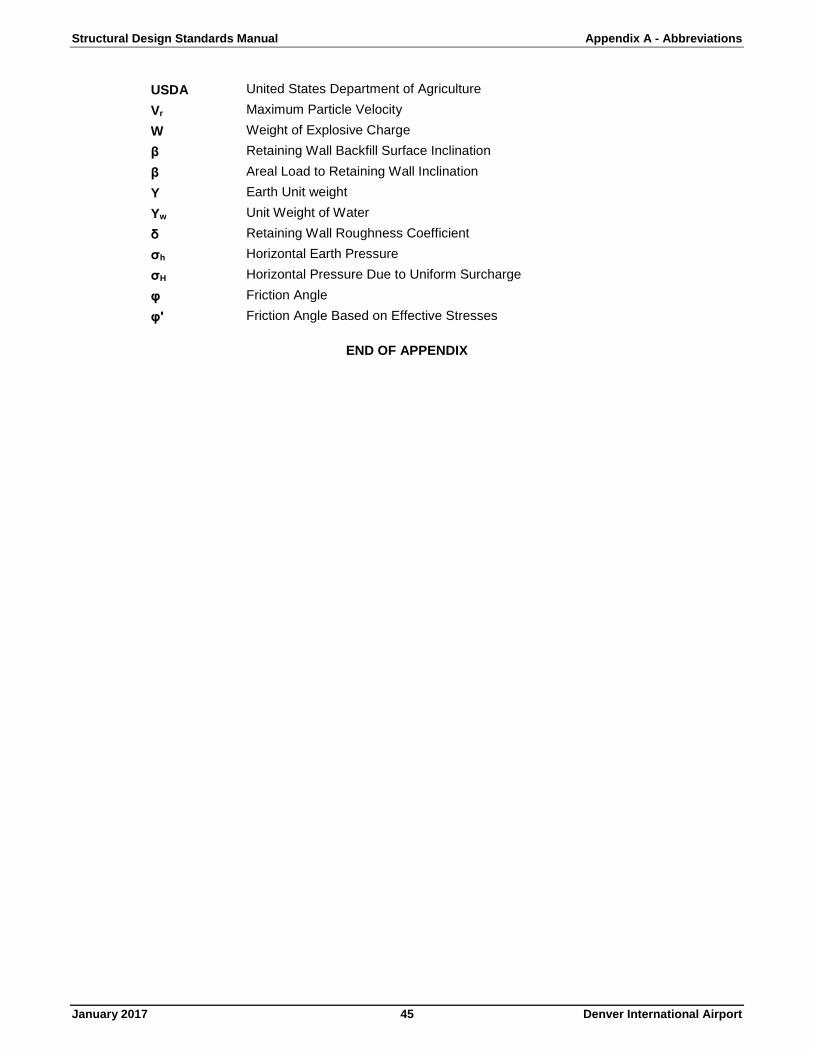
Structural Design Standards Manual Appendix A - Abbreviations
January 2017 45 Denver International Airport
USDA United States Department of Agriculture Vr Maximum Particle Velocity W Weight of Explosive Charge β Retaining Wall Backfill Surface Inclination β Areal Load to Retaining Wall Inclination Y Earth Unit weight Yw Unit Weight of Water δ Retaining Wall Roughness Coefficient σh Horizontal Earth Pressure σH Horizontal Pressure Due to Uniform Surcharge φ Friction Angle φ' Friction Angle Based on Effective Stresses
END OF APPENDIX
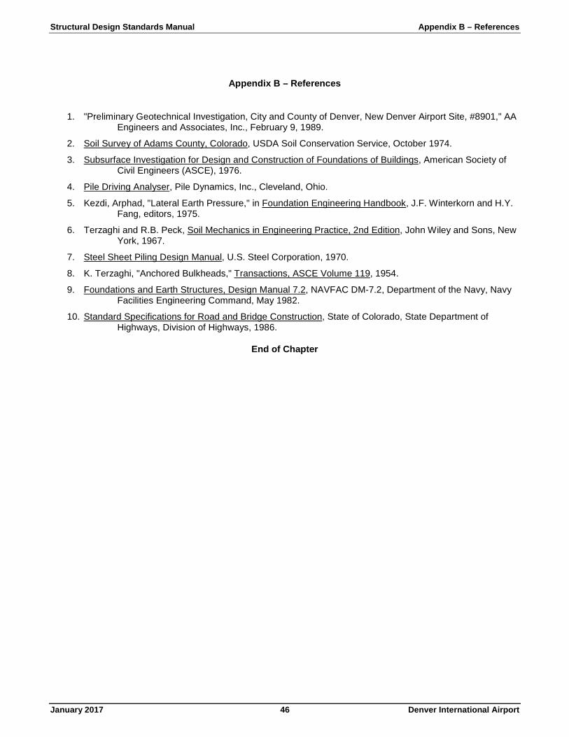
Structural Design Standards Manual Appendix B – References
January 2017 46 Denver International Airport
Appendix B – References
1. "Preliminary Geotechnical Investigation, City and County of Denver, New Denver Airport Site, #8901," AA Engineers and Associates, Inc., February 9, 1989.
2. Soil Survey of Adams County, Colorado, USDA Soil Conservation Service, October 1974.
3. Subsurface Investigation for Design and Construction of Foundations of Buildings, American Society of Civil Engineers (ASCE), 1976.
4. Pile Driving Analyser, Pile Dynamics, Inc., Cleveland, Ohio.
5. Kezdi, Arphad, "Lateral Earth Pressure," in Foundation Engineering Handbook, J.F. Winterkorn and H.Y. Fang, editors, 1975.
6. Terzaghi and R.B. Peck, Soil Mechanics in Engineering Practice, 2nd Edition, John Wiley and Sons, New York, 1967.
7. Steel Sheet Piling Design Manual, U.S. Steel Corporation, 1970.
8. K. Terzaghi, "Anchored Bulkheads," Transactions, ASCE Volume 119, 1954.
9. Foundations and Earth Structures, Design Manual 7.2, NAVFAC DM-7.2, Department of the Navy, Navy Facilities Engineering Command, May 1982.
10. Standard Specifications for Road and Bridge Construction, State of Colorado, State Department of Highways, Division of Highways, 1986.
End of Chapter

Structural Design Standards Manual Appendix B – References
January 2017 47 Denver International Airport