Embed Size (px)
Citation preview
Structural Calculations –Phenolic Composite, Acrylic, Tempered Glass Panel Systems- 1/4 in Low
Profile System, with Connection Elements & Fasteners Analysis WALL PANEL SYSTEMS, Inc. 421 Business Center Ct, Redlands, CA 92373
JN 3311 C
Louis Waldo Flores, P.E. Civil Engineer RCE 31666 (909) 213-3957
[email protected] 2164 Larimore Lane, Mentone, CA 92359
1
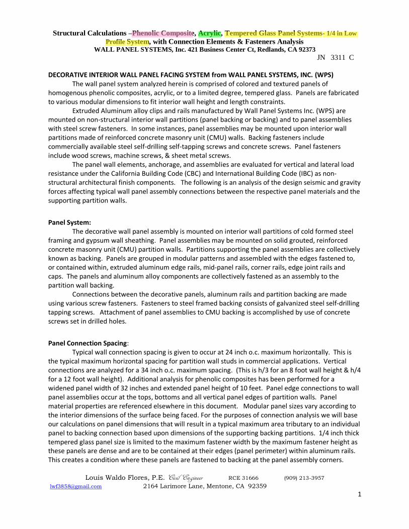
DECORATIVE INTERIOR WALL PANEL FACING SYSTEM from WALL PANEL SYSTEMS, INC. (WPS) The wall panel system analyzed herein is comprised of colored and textured panels of
homogenous phenolic composites, acrylic, or to a limited degree, tempered glass. Panels are fabricated to various modular dimensions to fit interior wall height and length constraints.
Extruded Aluminum alloy clips and rails manufactured by Wall Panel Systems Inc. (WPS) are mounted on non-structural interior wall partitions (panel backing or backing) and to panel assemblies with steel screw fasteners. In some instances, panel assemblies may be mounted upon interior wall partitions made of reinforced concrete masonry unit (CMU) walls. Backing fasteners include commercially available steel self-drilling self-tapping screws and concrete screws. Panel fasteners include wood screws, machine screws, & sheet metal screws.
The panel wall elements, anchorage, and assemblies are evaluated for vertical and lateral load resistance under the California Building Code (CBC) and International Building Code (IBC) as non-structural architectural finish components. The following is an analysis of the design seismic and gravity forces affecting typical wall panel assembly connections between the respective panel materials and the supporting partition walls.
Panel System: The decorative wall panel assembly is mounted on interior wall partitions of cold formed steel
framing and gypsum wall sheathing. Panel assemblies may be mounted on solid grouted, reinforced concrete masonry unit (CMU) partition walls. Partitions supporting the panel assemblies are collectively known as backing. Panels are grouped in modular patterns and assembled with the edges fastened to, or contained within, extruded aluminum edge rails, mid-panel rails, corner rails, edge joint rails and caps. The panels and aluminum alloy components are collectively fastened as an assembly to the partition wall backing.
Connections between the decorative panels, aluminum rails and partition backing are made using various screw fasteners. Fasteners to steel framed backing consists of galvanized steel self-drilling tapping screws. Attachment of panel assemblies to CMU backing is accomplished by use of concrete screws set in drilled holes.
Panel Connection Spacing: Typical wall connection spacing is given to occur at 24 inch o.c. maximum horizontally. This is
the typical maximum horizontal spacing for partition wall studs in commercial applications. Vertical connections are analyzed for a 34 inch o.c. maximum spacing. (This is h/3 for an 8 foot wall height & h/4 for a 12 foot wall height). Additional analysis for phenolic composites has been performed for a widened panel width of 32 inches and extended panel height of 10 feet. Panel edge connections to wall panel assemblies occur at the tops, bottoms and all vertical panel edges of partition walls. Panel material properties are referenced elsewhere in this document. Modular panel sizes vary according to the interior dimensions of the surface being faced. For the purposes of connection analysis we will base our calculations on panel dimensions that will result in a typical maximum area tributary to an individual panel to backing connection based upon dimensions of the supporting backing partitions. 1/4 inch thick tempered glass panel size is limited to the maximum fastener width by the maximum fastener height as these panels are dense and are to be contained at their edges (panel perimeter) within aluminum rails. This creates a condition where these panels are fastened to backing at the panel assembly corners.

Structural Calculations –Phenolic Composite, Acrylic, Tempered Glass Panel Systems- 1/4 in Low
Profile System, with Connection Elements & Fasteners Analysis WALL PANEL SYSTEMS, Inc. 421 Business Center Ct, Redlands, CA 92373
JN 3311 C
Louis Waldo Flores, P.E. Civil Engineer RCE 31666 (909) 213-3957
[email protected] 2164 Larimore Lane, Mentone, CA 92359
2
Tempered Glass Panel Dead Load (DL) = 3.2 PSF = [152.3 pcf x (0.25 in / 12 in per ft)]. Max. panel size = (fastener width max)(fastener height max) = (24 in)( 34 in)/12 in/ft2 = 5.67 sq.ft 19.1 lbs, DL = (3.2psf)(5.67sf+0.3) = Design DL Wt of Tempered Glass Assembly, 1/4 in thick.
1/4 in phenolic large panel limits DL/ fastener at 19.6 lbs. < 4.8 lbs = 19.1 lb / 4 fasteners at corners, OK. 5.67 sq. ft. = Typical maximum tributary area per connection = (24 in)(34 in)/ ( 12 in/ft )2. 26.7 sq. ft = Extended panel size = 32 in/(12 in/ft)(10 ft).
Panel System Unit Dead Loads ( DL ) per square foot (psf) are listed below. Each system is comprised of decorative panels, alloy components, and fasteners that collectively comprise each panel assembly.
2.2 PSF, DL = 1/4 in. thick Phenolic Composite Panel Assembly Design DL – Weight with clips. 1/4 in thick Panel Dead Load (DL) = 1.84 PSF = [88.3 pcf x (0.25 in / 12 in per ft)].
Tributary Dead Loads per connection for various Panel Assemblies: 12.5 lbs = 1/4 in. Phenolic Composite Panel Assembly Tributary DL = ( 5.67 sq.ft )( 2.2 psf ) 58.74 lbs = 1/4 in. Phenolic Composite Panel Assembly Tributary DL = ( 26.7 sq.ft )( 2.2 psf) 19.1 lbs = 1/4 in. Tempered Glass Panel Assembly Tributary DL = ( 5.67 sq.ft )( 3.2 psf ) 11.9 lbs = 1/4 in. Acrylic Composite Panel Assembly Tributary DL = ( 5.67 sq.ft )( 2.1 psf )
Therefore for system consistency we will analyze various connections based upon the maximum values each connection will likely support utilizing similarly sized fasteners for the various panel materials: Use 12.5 lbs / connection DL for design of backing screw seismic out of plane perpendicular to load. Use 58.74 lbs /connection DL for design of backing screw gravity connections, vertical condition.
Panel connections were analyzed for inverted sloping wall applications, including ceiling applications. Each panel assembly consists of: Modular Panels & extruded aluminum alloy edge rails are fastened to panel backing at all panel edges. Panel assembly vertical and horizontal joints utilize aluminum alloy joint rails fastened to panel backing at 24 in to 34 in spacing vertically; and horizontally at spacing that may vary from 16 in to 32 in oc. Edge rails and corner rails are connected to backing with galvanized steel self-drilling tapping screws conforming to AISI Standard for cold formed steel framing, or with hardened steel concrete screws set in drilled holes for reinforced concrete masonry unit walls (CMU). Aluminum alloy panel edge rails have formed pockets that contain the decorative phenolic, acrylic, and glass wall panels at the panel edges. ALUMINUM ALLOY EDGE RAILS & TRIM FOR 1/4 IN LOW PROFILE PANEL SYSTEMS ARE AS FOLLOWS: Edge Joint ( Part # 301 ), Wainscot Cap ( Part # 302 ), Square Cap ( Part # 303 ), Vertical Edge Trim ( Part # 305 ), Vertical Joint ( Part # 310 ), Wall Clip ( Part # 320 ), Corner Guard ( Part # 333 ) Cap B ( Part # 334 ) Cap A ( Part # 335 ) Inside Corner Guard ( Part # 341 ) Cap ( Part # 342 ) Horizontal Joint ( Part # 350 )
Structural Calculations –Phenolic Composite, Acrylic, Tempered Glass Panel Systems- 1/4 in Low
Profile System, with Connection Elements & Fasteners Analysis WALL PANEL SYSTEMS, Inc. 421 Business Center Ct, Redlands, CA 92373
JN 3311 C
Louis Waldo Flores, P.E. Civil Engineer RCE 31666 (909) 213-3957
[email protected] 2164 Larimore Lane, Mentone, CA 92359
3
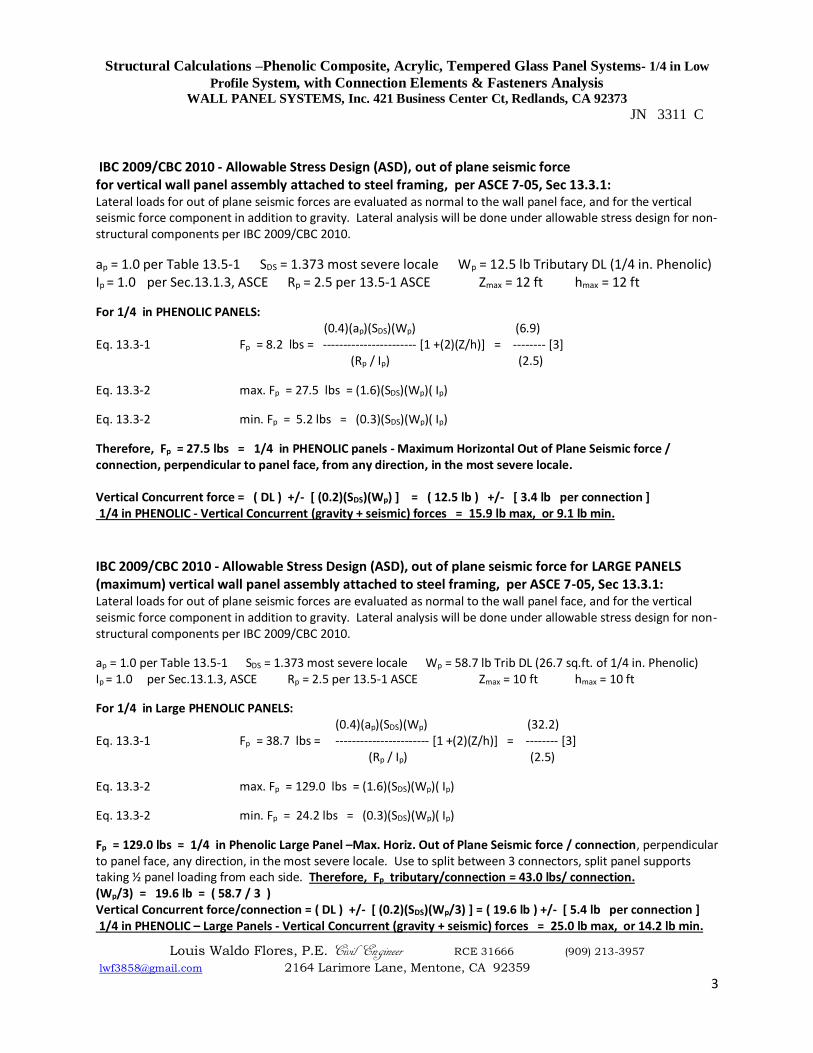
IBC 2009/CBC 2010 - Allowable Stress Design (ASD), out of plane seismic force for vertical wall panel assembly attached to steel framing, per ASCE 7-05, Sec 13.3.1: Lateral loads for out of plane seismic forces are evaluated as normal to the wall panel face, and for the vertical seismic force component in addition to gravity. Lateral analysis will be done under allowable stress design for non-structural components per IBC 2009/CBC 2010.
ap = 1.0 per Table 13.5-1 SDS = 1.373 most severe locale Wp = 12.5 lb Tributary DL (1/4 in. Phenolic) Ip = 1.0 per Sec.13.1.3, ASCE Rp = 2.5 per 13.5-1 ASCE Zmax = 12 ft hmax = 12 ft
For 1/4 in PHENOLIC PANELS: (0.4)(ap)(SDS)(Wp) (6.9) Eq. 13.3-1 Fp = 8.2 lbs = ----------------------- [1 +(2)(Z/h)] = -------- [3] (Rp / Ip) (2.5)
Eq. 13.3-2 max. Fp = 27.5 lbs = (1.6)(SDS)(Wp)( Ip)
Eq. 13.3-2 min. Fp = 5.2 lbs = (0.3)(SDS)(Wp)( Ip)
Therefore, Fp = 27.5 lbs = 1/4 in PHENOLIC panels - Maximum Horizontal Out of Plane Seismic force / connection, perpendicular to panel face, from any direction, in the most severe locale. Vertical Concurrent force = ( DL ) +/- [ (0.2)(SDS)(Wp) ] = ( 12.5 lb ) +/- [ 3.4 lb per connection ] 1/4 in PHENOLIC - Vertical Concurrent (gravity + seismic) forces = 15.9 lb max, or 9.1 lb min.
IBC 2009/CBC 2010 - Allowable Stress Design (ASD), out of plane seismic force for LARGE PANELS (maximum) vertical wall panel assembly attached to steel framing, per ASCE 7-05, Sec 13.3.1: Lateral loads for out of plane seismic forces are evaluated as normal to the wall panel face, and for the vertical seismic force component in addition to gravity. Lateral analysis will be done under allowable stress design for non-structural components per IBC 2009/CBC 2010.
ap = 1.0 per Table 13.5-1 SDS = 1.373 most severe locale Wp = 58.7 lb Trib DL (26.7 sq.ft. of 1/4 in. Phenolic) Ip = 1.0 per Sec.13.1.3, ASCE Rp = 2.5 per 13.5-1 ASCE Zmax = 10 ft hmax = 10 ft
For 1/4 in Large PHENOLIC PANELS: (0.4)(ap)(SDS)(Wp) (32.2) Eq. 13.3-1 Fp = 38.7 lbs = ----------------------- [1 +(2)(Z/h)] = -------- [3] (Rp / Ip) (2.5)
Eq. 13.3-2 max. Fp = 129.0 lbs = (1.6)(SDS)(Wp)( Ip)
Eq. 13.3-2 min. Fp = 24.2 lbs = (0.3)(SDS)(Wp)( Ip)
Fp = 129.0 lbs = 1/4 in Phenolic Large Panel –Max. Horiz. Out of Plane Seismic force / connection, perpendicular to panel face, any direction, in the most severe locale. Use to split between 3 connectors, split panel supports taking ½ panel loading from each side. Therefore, Fp tributary/connection = 43.0 lbs/ connection. (Wp/3) = 19.6 lb = ( 58.7 / 3 ) Vertical Concurrent force/connection = ( DL ) +/- [ (0.2)(SDS)(Wp/3) ] = ( 19.6 lb ) +/- [ 5.4 lb per connection ] 1/4 in PHENOLIC – Large Panels - Vertical Concurrent (gravity + seismic) forces = 25.0 lb max, or 14.2 lb min.
Structural Calculations –Phenolic Composite, Acrylic, Tempered Glass Panel Systems- 1/4 in Low
Profile System, with Connection Elements & Fasteners Analysis WALL PANEL SYSTEMS, Inc. 421 Business Center Ct, Redlands, CA 92373
JN 3311 C
Louis Waldo Flores, P.E. Civil Engineer RCE 31666 (909) 213-3957
[email protected] 2164 Larimore Lane, Mentone, CA 92359
4
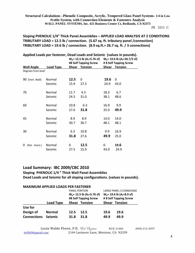
Sloping PHENOLIC 1/4” Thick Panel Assemblies – APPLIED LOAD ANALYSIS AT 2 CONDITIONS TRIBUTARY LOAD = 12.5 lb / connection. (5.67 sq. ft. tributary panel /connection) TRIBUTARY LOAD = 19.6 lb / connection. (8.9 sq.ft.= 26.7 sq. ft. / 3 connections) Applied Loads per fastener, Dead Loads and Seismic (values in pounds). Wp= 12.5 lb (At=5.76 sf) Wp= 19.6 lb (At=26.7/3 sf) #8 Self Tapping Screw # 8 Self Tapping Screw
Wall Angle Load Type Shear Tension Shear Tension Degrees from level
90 (Vert. Wall) Normal 12.5 0 19.6 0 Seismic 15.9 27.5 24.9 43.0
70 Normal 11.7 4.3 18.3 6.7 Seismic 24.3 31.0 38.1 48.6
60 Normal 10.8 6.3 16.9 9.9
Seismic 27.6 31.8 25.0 49.9 45 Normal 8.9 8.9 14.0 14.0
Seismic 30.7 30.7 48.1 48.1 30 Normal 6.3 10.8 9.9 16.9
Seismic 31.8 27.6 49.9 25.0
0 (flat - Horiz.) Normal 0 12.5 0 19.6 Seismic 27.5 15.9 43.0 24.9
Load Summary: IBC 2009/CBC 2010 Sloping PHENOLIC 1/4 ” Thick Wall Panel Assemblies Dead Loads and Seismic for all sloping configurations. (values in pounds). MAXIMUM APPLIED LOADS PER FASTENER PANEL PORTION LARGE PANEL-3 CONN/EDGE
Wp= 12.5 lb (At=5.76 sf) Wp= 19.6 lb (At=8.9 sf) #8 Self Tapping Screw # 8 Self Tapping Screw
Load Type Shear Tension Shear Tension Use for Design of Normal 12.5 12.5 19.6 19.6 Connections Seismic 31.8 31.8 49.9 49.9
Structural Calculations –Phenolic Composite, Acrylic, Tempered Glass Panel Systems- 1/4 in Low
Profile System, with Connection Elements & Fasteners Analysis WALL PANEL SYSTEMS, Inc. 421 Business Center Ct, Redlands, CA 92373
JN 3311 C
Louis Waldo Flores, P.E. Civil Engineer RCE 31666 (909) 213-3957
[email protected] 2164 Larimore Lane, Mentone, CA 92359
5
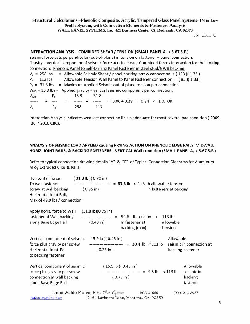
INTERACTION ANALYSIS – COMBINED SHEAR / TENSION (SMALL PANEL AP < 5.67 S.F.) Seismic force acts perpendicular (out-of-plane) in tension on fastener – panel connection. Gravity + vertical component of seismic force acts in shear. Combined forces interaction for the limiting connection: Phenolic Panel to Self-Drilling Panel Fastener in steel stud/GWB backing. Va = 258 lbs = Allowable Seismic Shear / panel backing screw connection = ( 193 )( 1.33 ). Pa = 113 lbs = Allowable Tension Wall Panel to Panel Fastener connection = ( 85 )( 1.33 ). Ps = 31.8 lbs = Maximum Applied Seismic out of plane tension per connection. VG+S = 15.9 lbs = Applied gravity + vertical seismic component per connection. VG+S Ps 15.9 31.8 ------ + ---- = ------ + ------ = 0.06 + 0.28 = 0.34 < 1.0, OK Va Pa 258 113 Interaction Analysis indicates weakest connection link is adequate for most severe load condition ( 2009 IBC / 2010 CBC). ANALYSIS OF SEISMIC LOAD APPLIED causing PRYING ACTION ON PHENOLIC EDGE RAILS, MIDWALL HORIZ. JOINT RAILS, & BACKING FASTENERS - VERTICAL Wall condition (SMALL PANEL AP < 5.67 S.F.) Refer to typical connection drawing details “A” & “E” of Typical Connection Diagrams for Aluminum Alloy Extruded Clips & Rails. Horizontal force ( 31.8 lb )( 0.70 in) To wall fastener -------------------------- = 63.6 lb < 113 lb allowable tension screw at wall backing, ( 0.35 in) in fasteners at backing Horizontal Joint Rail, Max of 49.9 lbs / connection. Apply horiz. force to Wall (31.8 lb)(0.75 in) fastener at Wall backing ------------------------ = 59.6 lb tension < 113 lb along Base Edge Rail (0.40 in) In fastener at allowable backing (max) tension Vertical component of seismic ( 15.9 lb )( 0.45 in ) Allowable force plus gravity per screw ------------------------- = 20.4 lb < 113 lb seismic in connection at Horizontal Joint Rail ( 0.35 in ) backing fastener to backing fastener Vertical component of seismic ( 15.9 lb )( 0.45 in ) Allowable force plus gravity per screw -------------------------- = 9.5 lb < 113 lb seismic in connection at wall backing ( 0.75 in ) backing along Base Edge Rail fastener
Structural Calculations –Phenolic Composite, Acrylic, Tempered Glass Panel Systems- 1/4 in Low
Profile System, with Connection Elements & Fasteners Analysis WALL PANEL SYSTEMS, Inc. 421 Business Center Ct, Redlands, CA 92373
JN 3311 C
Louis Waldo Flores, P.E. Civil Engineer RCE 31666 (909) 213-3957
[email protected] 2164 Larimore Lane, Mentone, CA 92359
6
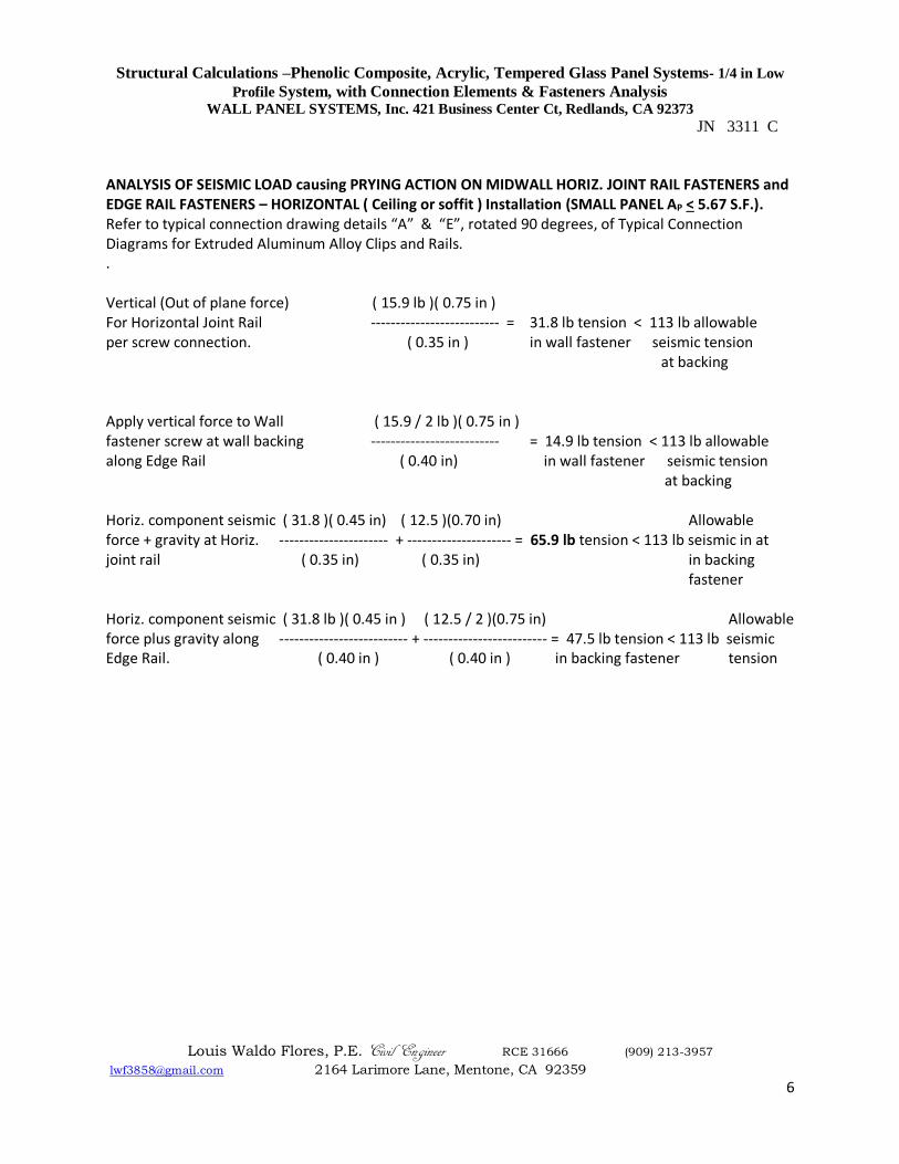
ANALYSIS OF SEISMIC LOAD causing PRYING ACTION ON MIDWALL HORIZ. JOINT RAIL FASTENERS and EDGE RAIL FASTENERS – HORIZONTAL ( Ceiling or soffit ) Installation (SMALL PANEL AP < 5.67 S.F.). Refer to typical connection drawing details “A” & “E”, rotated 90 degrees, of Typical Connection Diagrams for Extruded Aluminum Alloy Clips and Rails. . Vertical (Out of plane force) ( 15.9 lb )( 0.75 in ) For Horizontal Joint Rail -------------------------- = 31.8 lb tension < 113 lb allowable per screw connection. ( 0.35 in ) in wall fastener seismic tension at backing Apply vertical force to Wall ( 15.9 / 2 lb )( 0.75 in ) fastener screw at wall backing -------------------------- = 14.9 lb tension < 113 lb allowable along Edge Rail ( 0.40 in) in wall fastener seismic tension at backing Horiz. component seismic ( 31.8 )( 0.45 in) ( 12.5 )(0.70 in) Allowable force + gravity at Horiz. ---------------------- + --------------------- = 65.9 lb tension < 113 lb seismic in at joint rail ( 0.35 in) ( 0.35 in) in backing fastener Horiz. component seismic ( 31.8 lb )( 0.45 in ) ( 12.5 / 2 )(0.75 in) Allowable force plus gravity along -------------------------- + ------------------------- = 47.5 lb tension < 113 lb seismic Edge Rail. ( 0.40 in ) ( 0.40 in ) in backing fastener tension
Structural Calculations –Phenolic Composite, Acrylic, Tempered Glass Panel Systems- 1/4 in Low
Profile System, with Connection Elements & Fasteners Analysis WALL PANEL SYSTEMS, Inc. 421 Business Center Ct, Redlands, CA 92373
JN 3311 C
Louis Waldo Flores, P.E. Civil Engineer RCE 31666 (909) 213-3957
[email protected] 2164 Larimore Lane, Mentone, CA 92359
7
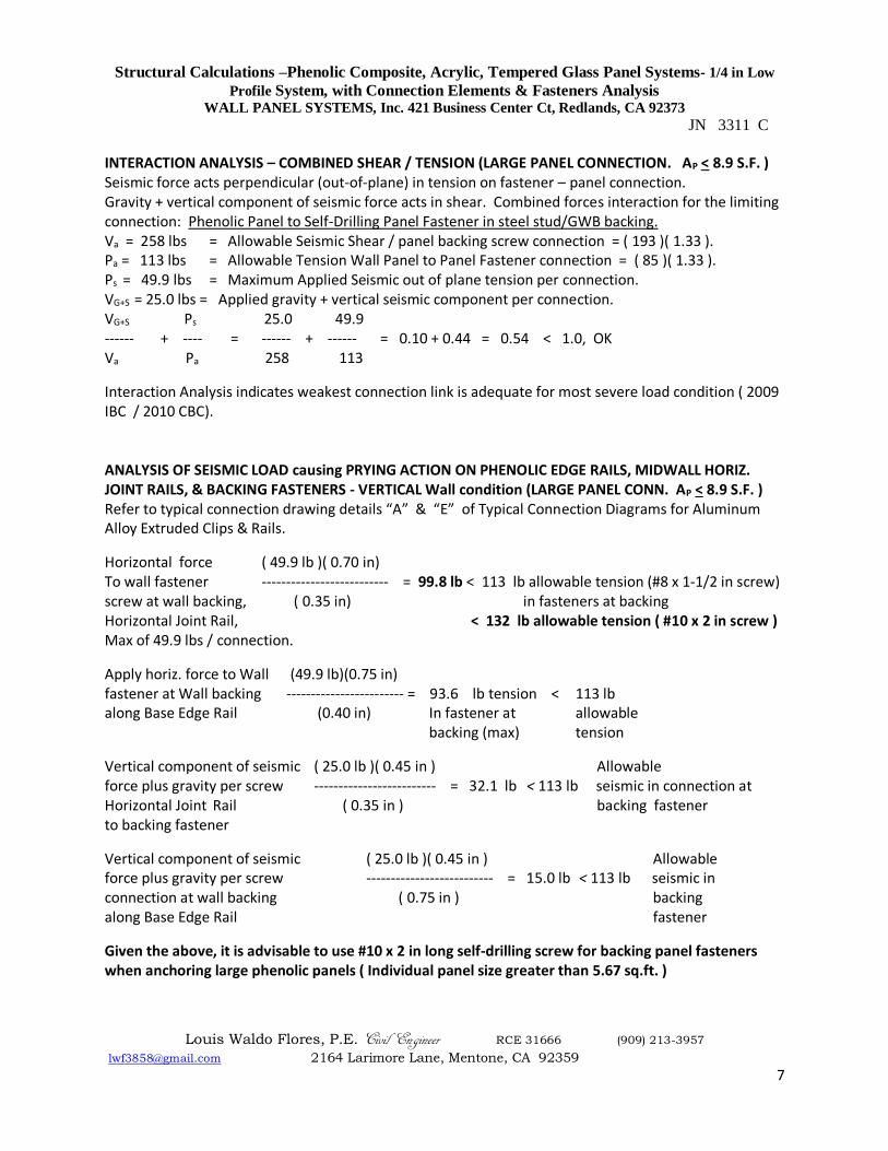
INTERACTION ANALYSIS – COMBINED SHEAR / TENSION (LARGE PANEL CONNECTION. AP < 8.9 S.F. ) Seismic force acts perpendicular (out-of-plane) in tension on fastener – panel connection. Gravity + vertical component of seismic force acts in shear. Combined forces interaction for the limiting connection: Phenolic Panel to Self-Drilling Panel Fastener in steel stud/GWB backing. Va = 258 lbs = Allowable Seismic Shear / panel backing screw connection = ( 193 )( 1.33 ). Pa = 113 lbs = Allowable Tension Wall Panel to Panel Fastener connection = ( 85 )( 1.33 ). Ps = 49.9 lbs = Maximum Applied Seismic out of plane tension per connection. VG+S = 25.0 lbs = Applied gravity + vertical seismic component per connection. VG+S Ps 25.0 49.9 ------ + ---- = ------ + ------ = 0.10 + 0.44 = 0.54 < 1.0, OK Va Pa 258 113
Interaction Analysis indicates weakest connection link is adequate for most severe load condition ( 2009 IBC / 2010 CBC). ANALYSIS OF SEISMIC LOAD causing PRYING ACTION ON PHENOLIC EDGE RAILS, MIDWALL HORIZ. JOINT RAILS, & BACKING FASTENERS - VERTICAL Wall condition (LARGE PANEL CONN. AP < 8.9 S.F. ) Refer to typical connection drawing details “A” & “E” of Typical Connection Diagrams for Aluminum Alloy Extruded Clips & Rails.
Horizontal force ( 49.9 lb )( 0.70 in) To wall fastener -------------------------- = 99.8 lb < 113 lb allowable tension (#8 x 1-1/2 in screw) screw at wall backing, ( 0.35 in) in fasteners at backing Horizontal Joint Rail, < 132 lb allowable tension ( #10 x 2 in screw ) Max of 49.9 lbs / connection.
Apply horiz. force to Wall (49.9 lb)(0.75 in) fastener at Wall backing ------------------------ = 93.6 lb tension < 113 lb along Base Edge Rail (0.40 in) In fastener at allowable backing (max) tension
Vertical component of seismic ( 25.0 lb )( 0.45 in ) Allowable force plus gravity per screw ------------------------- = 32.1 lb < 113 lb seismic in connection at Horizontal Joint Rail ( 0.35 in ) backing fastener to backing fastener
Vertical component of seismic ( 25.0 lb )( 0.45 in ) Allowable force plus gravity per screw -------------------------- = 15.0 lb < 113 lb seismic in connection at wall backing ( 0.75 in ) backing along Base Edge Rail fastener
Given the above, it is advisable to use #10 x 2 in long self-drilling screw for backing panel fasteners when anchoring large phenolic panels ( Individual panel size greater than 5.67 sq.ft. )
Structural Calculations –Phenolic Composite, Acrylic, Tempered Glass Panel Systems- 1/4 in Low
Profile System, with Connection Elements & Fasteners Analysis WALL PANEL SYSTEMS, Inc. 421 Business Center Ct, Redlands, CA 92373
JN 3311 C
Louis Waldo Flores, P.E. Civil Engineer RCE 31666 (909) 213-3957
[email protected] 2164 Larimore Lane, Mentone, CA 92359
8
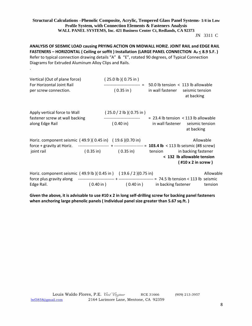
ANALYSIS OF SEISMIC LOAD causing PRYING ACTION ON MIDWALL HORIZ. JOINT RAIL and EDGE RAIL FASTENERS – HORIZONTAL ( Ceiling or soffit ) Installation (LARGE PANEL CONNECTION AP < 8.9 S.F. ) Refer to typical connection drawing details “A” & “E”, rotated 90 degrees, of Typical Connection Diagrams for Extruded Aluminum Alloy Clips and Rails. . Vertical (Out of plane force) ( 25.0 lb )( 0.75 in ) For Horizontal Joint Rail -------------------------- = 50.0 lb tension < 113 lb allowable per screw connection. ( 0.35 in ) in wall fastener seismic tension at backing Apply vertical force to Wall ( 25.0 / 2 lb )( 0.75 in ) fastener screw at wall backing -------------------------- = 23.4 lb tension < 113 lb allowable along Edge Rail ( 0.40 in) in wall fastener seismic tension at backing Horiz. component seismic ( 49.9 )( 0.45 in) ( 19.6 )(0.70 in) Allowable force + gravity at Horiz. ---------------------- + --------------------- = 103.4 lb < 113 lb seismic (#8 screw) joint rail ( 0.35 in) ( 0.35 in) tension in backing fastener
< 132 lb allowable tension ( #10 x 2 in screw )
Horiz. component seismic ( 49.9 lb )( 0.45 in ) ( 19.6 / 2 )(0.75 in) Allowable force plus gravity along -------------------------- + ------------------------- = 74.5 lb tension < 113 lb seismic Edge Rail. ( 0.40 in ) ( 0.40 in ) in backing fastener tension Given the above, it is advisable to use #10 x 2 in long self-drilling screw for backing panel fasteners when anchoring large phenolic panels ( Individual panel size greater than 5.67 sq.ft. )
Structural Calculations –Phenolic Composite, Acrylic, Tempered Glass Panel Systems- 1/4 in Low
Profile System, with Connection Elements & Fasteners Analysis WALL PANEL SYSTEMS, Inc. 421 Business Center Ct, Redlands, CA 92373
JN 3311 C
Louis Waldo Flores, P.E. Civil Engineer RCE 31666 (909) 213-3957
[email protected] 2164 Larimore Lane, Mentone, CA 92359
9
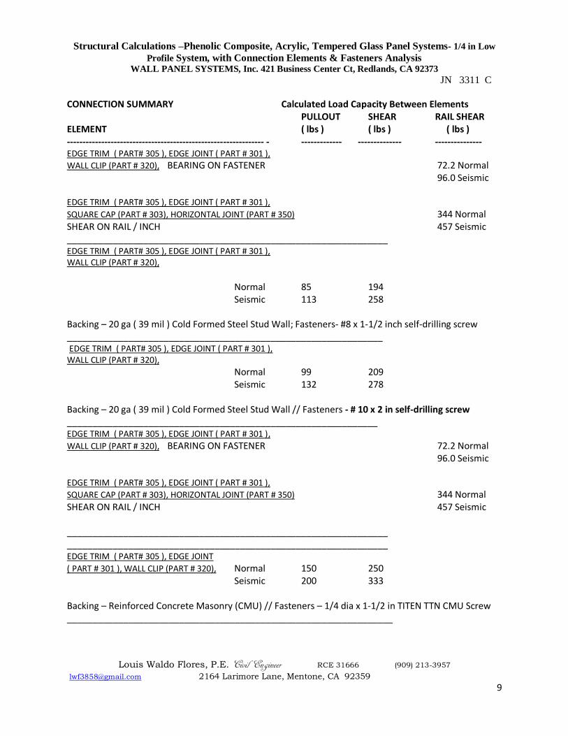
CONNECTION SUMMARY Calculated Load Capacity Between Elements PULLOUT SHEAR RAIL SHEAR ELEMENT ( lbs ) ( lbs ) ( lbs ) --------------------------------------------------------------- - ------------- -------------- --------------- EDGE TRIM ( PART# 305 ), EDGE JOINT ( PART # 301 ),
WALL CLIP (PART # 320), BEARING ON FASTENER 72.2 Normal 96.0 Seismic EDGE TRIM ( PART# 305 ), EDGE JOINT ( PART # 301 ),
SQUARE CAP (PART # 303), HORIZONTAL JOINT (PART # 350) 344 Normal SHEAR ON RAIL / INCH 457 Seismic _______________________________________________________________ EDGE TRIM ( PART# 305 ), EDGE JOINT ( PART # 301 ), WALL CLIP (PART # 320), Normal 85 194 Seismic 113 258 Backing – 20 ga ( 39 mil ) Cold Formed Steel Stud Wall; Fasteners- #8 x 1-1/2 inch self-drilling screw ______________________________________________________________ EDGE TRIM ( PART# 305 ), EDGE JOINT ( PART # 301 ), WALL CLIP (PART # 320), Normal 99 209 Seismic 132 278 Backing – 20 ga ( 39 mil ) Cold Formed Steel Stud Wall // Fasteners - # 10 x 2 in self-drilling screw _____________________________________________________________ EDGE TRIM ( PART# 305 ), EDGE JOINT ( PART # 301 ),
WALL CLIP (PART # 320), BEARING ON FASTENER 72.2 Normal 96.0 Seismic EDGE TRIM ( PART# 305 ), EDGE JOINT ( PART # 301 ),
SQUARE CAP (PART # 303), HORIZONTAL JOINT (PART # 350) 344 Normal SHEAR ON RAIL / INCH 457 Seismic _______________________________________________________________ _______________________________________________________________ EDGE TRIM ( PART# 305 ), EDGE JOINT
( PART # 301 ), WALL CLIP (PART # 320), Normal 150 250 Seismic 200 333 Backing – Reinforced Concrete Masonry (CMU) // Fasteners – 1/4 dia x 1-1/2 in TITEN TTN CMU Screw ________________________________________________________________
Structural Calculations –Phenolic Composite, Acrylic, Tempered Glass Panel Systems- 1/4 in Low
Profile System, with Connection Elements & Fasteners Analysis WALL PANEL SYSTEMS, Inc. 421 Business Center Ct, Redlands, CA 92373
JN 3311 C
Louis Waldo Flores, P.E. Civil Engineer RCE 31666 (909) 213-3957
[email protected] 2164 Larimore Lane, Mentone, CA 92359
10
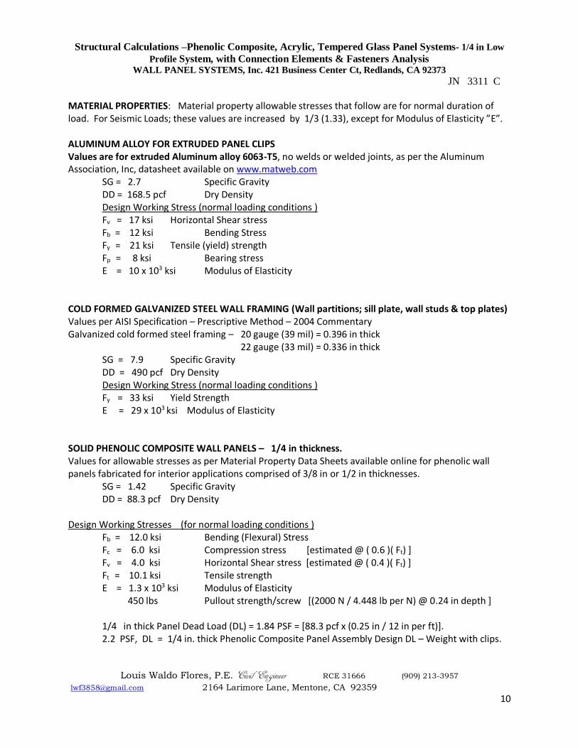
MATERIAL PROPERTIES: Material property allowable stresses that follow are for normal duration of load. For Seismic Loads; these values are increased by 1/3 (1.33), except for Modulus of Elasticity ”E”. ALUMINUM ALLOY FOR EXTRUDED PANEL CLIPS Values are for extruded Aluminum alloy 6063-T5, no welds or welded joints, as per the Aluminum Association, Inc, datasheet available on www.matweb.com
SG = 2.7 Specific Gravity DD = 168.5 pcf Dry Density Design Working Stress (normal loading conditions )
Fv = 17 ksi Horizontal Shear stress Fb = 12 ksi Bending Stress Fy = 21 ksi Tensile (yield) strength Fp = 8 ksi Bearing stress
E = 10 x 103 ksi Modulus of Elasticity COLD FORMED GALVANIZED STEEL WALL FRAMING (Wall partitions; sill plate, wall studs & top plates) Values per AISI Specification – Prescriptive Method – 2004 Commentary Galvanized cold formed steel framing – 20 gauge (39 mil) = 0.396 in thick
22 gauge (33 mil) = 0.336 in thick SG = 7.9 Specific Gravity
DD = 490 pcf Dry Density Design Working Stress (normal loading conditions )
Fy = 33 ksi Yield Strength E = 29 x 103 ksi Modulus of Elasticity
SOLID PHENOLIC COMPOSITE WALL PANELS – 1/4 in thickness. Values for allowable stresses as per Material Property Data Sheets available online for phenolic wall panels fabricated for interior applications comprised of 3/8 in or 1/2 in thicknesses.
SG = 1.42 Specific Gravity DD = 88.3 pcf Dry Density
Design Working Stresses (for normal loading conditions )
Fb = 12.0 ksi Bending (Flexural) Stress Fc = 6.0 ksi Compression stress [estimated @ ( 0.6 )( Ft) ] Fv = 4.0 ksi Horizontal Shear stress [estimated @ ( 0.4 )( Ft) ]
Ft = 10.1 ksi Tensile strength E = 1.3 x 10³ ksi Modulus of Elasticity
450 lbs Pullout strength/screw [(2000 N / 4.448 lb per N) @ 0.24 in depth ] 1/4 in thick Panel Dead Load (DL) = 1.84 PSF = [88.3 pcf x (0.25 in / 12 in per ft)]. 2.2 PSF, DL = 1/4 in. thick Phenolic Composite Panel Assembly Design DL – Weight with clips.
Structural Calculations –Phenolic Composite, Acrylic, Tempered Glass Panel Systems- 1/4 in Low
Profile System, with Connection Elements & Fasteners Analysis WALL PANEL SYSTEMS, Inc. 421 Business Center Ct, Redlands, CA 92373
JN 3311 C
Louis Waldo Flores, P.E. Civil Engineer RCE 31666 (909) 213-3957
[email protected] 2164 Larimore Lane, Mentone, CA 92359
11
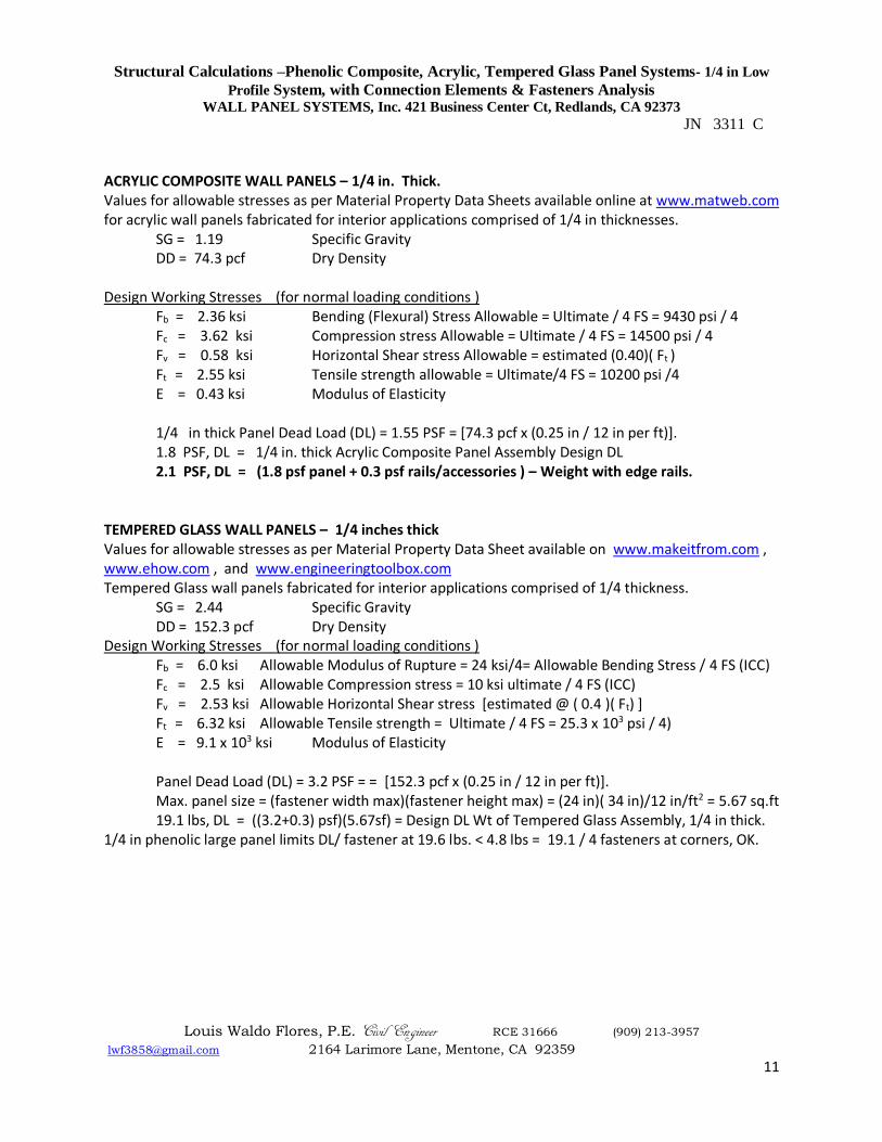
ACRYLIC COMPOSITE WALL PANELS – 1/4 in. Thick. Values for allowable stresses as per Material Property Data Sheets available online at www.matweb.com for acrylic wall panels fabricated for interior applications comprised of 1/4 in thicknesses.
SG = 1.19 Specific Gravity DD = 74.3 pcf Dry Density Design Working Stresses (for normal loading conditions )
Fb = 2.36 ksi Bending (Flexural) Stress Allowable = Ultimate / 4 FS = 9430 psi / 4 Fc = 3.62 ksi Compression stress Allowable = Ultimate / 4 FS = 14500 psi / 4 Fv = 0.58 ksi Horizontal Shear stress Allowable = estimated (0.40)( Ft )
Ft = 2.55 ksi Tensile strength allowable = Ultimate/4 FS = 10200 psi /4 E = 0.43 ksi Modulus of Elasticity
1/4 in thick Panel Dead Load (DL) = 1.55 PSF = [74.3 pcf x (0.25 in / 12 in per ft)]. 1.8 PSF, DL = 1/4 in. thick Acrylic Composite Panel Assembly Design DL 2.1 PSF, DL = (1.8 psf panel + 0.3 psf rails/accessories ) – Weight with edge rails.
TEMPERED GLASS WALL PANELS – 1/4 inches thick Values for allowable stresses as per Material Property Data Sheet available on www.makeitfrom.com , www.ehow.com , and www.engineeringtoolbox.com Tempered Glass wall panels fabricated for interior applications comprised of 1/4 thickness.
SG = 2.44 Specific Gravity DD = 152.3 pcf Dry Density Design Working Stresses (for normal loading conditions )
Fb = 6.0 ksi Allowable Modulus of Rupture = 24 ksi/4= Allowable Bending Stress / 4 FS (ICC) Fc = 2.5 ksi Allowable Compression stress = 10 ksi ultimate / 4 FS (ICC) Fv = 2.53 ksi Allowable Horizontal Shear stress [estimated @ ( 0.4 )( Ft) ]
Ft = 6.32 ksi Allowable Tensile strength = Ultimate / 4 FS = 25.3 x 10³ psi / 4) E = 9.1 x 10³ ksi Modulus of Elasticity
Panel Dead Load (DL) = 3.2 PSF = = [152.3 pcf x (0.25 in / 12 in per ft)]. Max. panel size = (fastener width max)(fastener height max) = (24 in)( 34 in)/12 in/ft2 = 5.67 sq.ft 19.1 lbs, DL = ((3.2+0.3) psf)(5.67sf) = Design DL Wt of Tempered Glass Assembly, 1/4 in thick.
1/4 in phenolic large panel limits DL/ fastener at 19.6 lbs. < 4.8 lbs = 19.1 / 4 fasteners at corners, OK.
Structural Calculations –Phenolic Composite, Acrylic, Tempered Glass Panel Systems- 1/4 in Low
Profile System, with Connection Elements & Fasteners Analysis WALL PANEL SYSTEMS, Inc. 421 Business Center Ct, Redlands, CA 92373
JN 3311 C
Louis Waldo Flores, P.E. Civil Engineer RCE 31666 (909) 213-3957
[email protected] 2164 Larimore Lane, Mentone, CA 92359
12
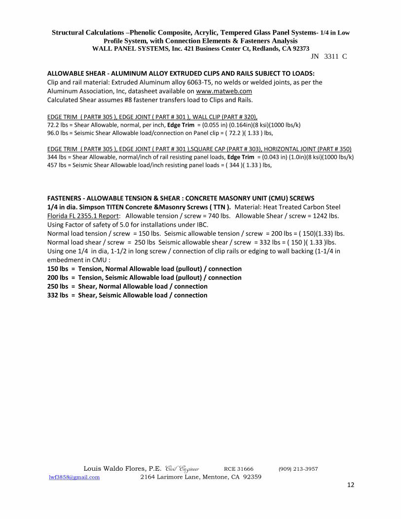
ALLOWABLE SHEAR - ALUMINUM ALLOY EXTRUDED CLIPS AND RAILS SUBJECT TO LOADS: Clip and rail material: Extruded Aluminum alloy 6063-T5, no welds or welded joints, as per the Aluminum Association, Inc, datasheet available on www.matweb.com Calculated Shear assumes #8 fastener transfers load to Clips and Rails. EDGE TRIM ( PART# 305 ), EDGE JOINT ( PART # 301 ), WALL CLIP (PART # 320), 72.2 lbs = Shear Allowable, normal, per inch, Edge Trim = (0.055 in) (0.164in)(8 ksi)(1000 lbs/k) 96.0 lbs = Seismic Shear Allowable load/connection on Panel clip = ( 72.2 )( 1.33 ) lbs, EDGE TRIM ( PART# 305 ), EDGE JOINT ( PART # 301 ),SQUARE CAP (PART # 303), HORIZONTAL JOINT (PART # 350) 344 lbs = Shear Allowable, normal/inch of rail resisting panel loads, Edge Trim = (0.043 in) (1.0in)(8 ksi)(1000 lbs/k) 457 lbs = Seismic Shear Allowable load/inch resisting panel loads = ( 344 )( 1.33 ) lbs,
FASTENERS - ALLOWABLE TENSION & SHEAR : CONCRETE MASONRY UNIT (CMU) SCREWS 1/4 in dia. Simpson TITEN Concrete &Masonry Screws ( TTN ). Material: Heat Treated Carbon Steel Florida FL 2355.1 Report: Allowable tension / screw = 740 lbs. Allowable Shear / screw = 1242 lbs. Using Factor of safety of 5.0 for installations under IBC. Normal load tension / screw = 150 lbs. Seismic allowable tension / screw = 200 lbs = ( 150)(1.33) lbs. Normal load shear / screw = 250 lbs Seismic allowable shear / screw = 332 lbs = ( 150 )( 1.33 )lbs. Using one 1/4 in dia, 1-1/2 in long screw / connection of clip rails or edging to wall backing (1-1/4 in embedment in CMU : 150 lbs = Tension, Normal Allowable load (pullout) / connection 200 lbs = Tension, Seismic Allowable load (pullout) / connection 250 lbs = Shear, Normal Allowable load / connection 332 lbs = Shear, Seismic Allowable load / connection
Structural Calculations –Phenolic Composite, Acrylic, Tempered Glass Panel Systems- 1/4 in Low
Profile System, with Connection Elements & Fasteners Analysis WALL PANEL SYSTEMS, Inc. 421 Business Center Ct, Redlands, CA 92373
JN 3311 C
Louis Waldo Flores, P.E. Civil Engineer RCE 31666 (909) 213-3957
[email protected] 2164 Larimore Lane, Mentone, CA 92359
13
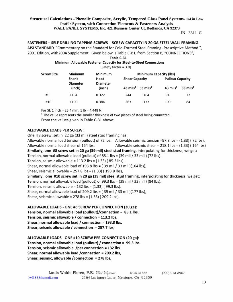
FASTENERS – SELF DRILLING TAPPING SCREWS – SCREW CAPACITY IN 20 GA STEEL WALL FRAMING. AISI STANDARD “Commentary on the Standard for Cold-Formed Steel Framing -Prescriptive Method ”, 2001 Edition, with2004 Supplement. Given below is Table C-B1, from Section B, “CONNECTIONS”,
Table C-B1 Minimum Allowable Fastener Capacity for Steel-to-Steel Connections
[Safety factor = 3.0]
Screw Size Minimum Minimum Minimum Capacity (lbs) Shank Head Shear Capacity Pullout Capacity
Diameter Diameter (inch) (inch) 43 mils1 33 mils1 43 mils1 33 mils1
#8 0.164 0.322 244 164 94 72
#10 0.190 0.384 263 177 109 84
For SI: 1 inch = 25.4 mm, 1 lb = 4.448 N. 1 The value represents the smaller thickness of two pieces of steel being connected.
From the values given in Table C-B1 above: ALLOWABLE LOADS PER SCREW: One #8 screw, set in 22 ga (33 mil) steel stud framing has: Allowable normal load tension (pullout) of 72 lbs. Allowable seismic tension =97.8 lbs = (1.33) ( 72 lbs). Allowable normal load shear of 164 lbs. Allowable seismic shear = 218.1 lbs = (1.33) ( 164 lbs) Similarly, one #8 screw set in 20 ga (39 mil) steel stud framing, interpolating for thickness, we get: Tension, normal allowable load (pullout) of 85.1 lbs = (39 mil / 33 mil ) (72 lbs). Tension, seismic allowable = 113.2 lbs = (1.33) ( 85.3 lbs). Shear, normal allowable load of 193.8 lbs = ( 39 mil / 33 mil )(164 lbs), Shear, seismic allowable = 257.8 lbs = (1.33) ( 193.8 lbs), Similarly, one #10 screw set in 20 ga (39 mil) steel stud framing, interpolating for thickness, we get: Tension, normal allowable load (pullout) of 99.3 lbs = (39 mil / 33 mil ) (84 lbs). Tension, seismic allowable = 132 lbs = (1.33) ( 99.3 lbs). Shear, normal allowable load of 209.2 lbs = ( 39 mil / 33 mil )(177 lbs), Shear, seismic allowable = 278 lbs = (1.33) ( 209.2 lbs), ALLOWABLE LOADS - ONE #8 SCREW PER CONNECTION (20 ga): Tension, normal allowable load (pullout)/connection = 85.1 lbs. Tension, seismic allowable / connection = 113.2 lbs. Shear, normal allowable load / connection = 193.8 lbs, Shear, seismic allowable / connection = 257.7 lbs, ALLOWABLE LOADS - ONE #10 SCREW PER CONNECTION (20 ga): Tension, normal allowable load (pullout) / connection = 99.3 lbs. Tension, seismic allowable /per connection = 132 lbs. Shear, normal allowable load /connection = 209.2 lbs, Shear, seismic, allowable /connection = 278 lbs,
Structural Calculations –Phenolic Composite, Acrylic, Tempered Glass Panel Systems- 1/4 in Low
Profile System, with Connection Elements & Fasteners Analysis WALL PANEL SYSTEMS, Inc. 421 Business Center Ct, Redlands, CA 92373
JN 3311 C
Louis Waldo Flores, P.E. Civil Engineer RCE 31666 (909) 213-3957
[email protected] 2164 Larimore Lane, Mentone, CA 92359
14
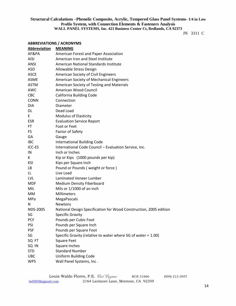
ABBREVIATIONS / ACRONYMS Abbreviation MEANING AF&PA American Forest and Paper Association AISI American Iron and Steel Institute ANSI American National Standards Institute ASD Allowable Stress Design ASCE American Society of Civil Engineers ASME American Society of Mechanical Engineers ASTM American Society of Testing and Materials AWC American Wood Council CBC California Building Code CONN Connection DIA Diameter DL Dead Load E Modulus of Elasticity ESR Evaluation Service Report FT Foot or Feet FS Factor of Safety GA Gauge IBC International Building Code ICC-ES International Code Council – Evaluation Service, Inc. IN Inch or Inches K Kip or Kips (1000 pounds per kip) KSI Kips per Square Inch LB Pound or Pounds ( weight or force ) LL Live Load LVL Laminated Veneer Lumber MDF Medium Density Fiberboard MIL Mils or 1/1000 of an inch MM Millimeters MPa MegaPascals N Newtons NDS-2005 National Design Specification for Wood Construction, 2005 edition SG Specific Gravity PCF Pounds per Cubic Foot PSI Pounds per Square Inch PSF Pounds per Square Foot SG Specific Gravity (relative to water where SG of water = 1.00) SQ FT Square Feet SQ IN Square Inches STD Standard Number UBC Uniform Building Code WPS Wall Panel Systems, Inc .
Structural Calculations –Phenolic Composite, Acrylic, Tempered Glass Panel Systems- 1/4 in Low
Profile System, with Connection Elements & Fasteners Analysis WALL PANEL SYSTEMS, Inc. 421 Business Center Ct, Redlands, CA 92373
JN 3311 C
Louis Waldo Flores, P.E. Civil Engineer RCE 31666 (909) 213-3957
[email protected] 2164 Larimore Lane, Mentone, CA 92359
15
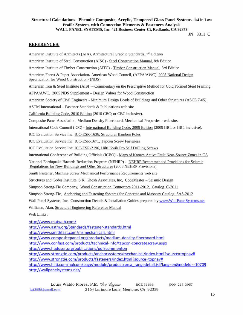
REFERENCES: American Institute of Architects (AIA), Architectural Graphic Standards, 7th Edition
American Institute of Steel Construction (AISC) - Steel Construction Manual, 8th Edition
American Institute of Timber Construction (AITC) - Timber Construction Manual, 3rd Edition
American Forest & Paper Association/ American Wood Council, (AFPA/AWC) 2005 National Design
Specification for Wood Construction- (NDS)
American Iron & Steel Institute (AISI) – Commentary on the Prescriptive Method for Cold Formed Steel Framing,
AFPA/AWC, 2005 NDS Supplement – Design Values for Wood Construction
American Society of Civil Engineers - Minimum Design Loads of Buildings and Other Structures (ASCE 7-05)
ASTM International – Fastener Standards & Publications web site.
California Building Code, 2010 Edition (2010 CBC; or CBC inclusive).
Composite Panel Association, Medium Density Fiberboard, Mechanical Properties - web site.
International Code Council (ICC) - International Building Code, 2009 Edition (2009 IBC, or IBC, inclusive).
ICC Evaluation Service Inc. ICC-ESR-1636, Structural Bamboo Poles
ICC Evaluation Service Inc. ICC-ESR-1671, Tapcon Screw Fasteners
ICC Evaluation Service Inc. ICC-ESR-2196, Hilti Kwik Pro Self Drilling Screws
International Conference of Building Officials (ICBO) - Maps of Known Active Fault Near-Source Zones in CA
National Earthquake Hazards Reduction Program (NEHRP) - NEHRP Recommended Provisions for Seismic
Regulations for New Buildings and Other Structures (2003 NEHRP Provisions).
Smith Fastener, Machine Screw Mechanical Performance Requirements web site
Structures and Codes Institute, S.K. Ghosh Associates, Inc, CodeMaster – Seismic Design
Simpson Strong-Tie Company, Wood Construction Connectors 2011-2012, Catalog C-2011
Simpson Strong-Tie, Anchoring and Fastening Systems for Concrete and Masonry Catalog SAS-2012
Wall Panel Systems, Inc, Construction Details & Installation Guides prepared by www.WallPanelSystems.net
Williams, Alan, Structural Engineering Reference Manual
Web Links :
http://www.matweb.com/ http://www.astm.org/Standards/fastener-standards.html http://www.smithfast.com/msmechanicals.html http://www.compositepanel.org/products/medium-density-fiberboard.html http://www.confast.com/products/technical-info/tapcon-concretescrew.aspx http://www.huduser.org/publications/pdf/commenton http://www.strongtie.com/products/anchorsystems/mechanical/index.html?source=topnav# http://www.strongtie.com/products/fasteners/index.html?source=topnav# http://www.hilti.com/holcom/page/module/product/prca_rangedetail.jsf?lang=en&nodeId=-10709 http://wallpanelsystems.net/