Embed Size (px)
Citation preview
STRUCTURAL CALCULATIONS – EXTERIOR WALL CLADDING PANEL SYSTEM Phenolic Panels, Laminated Wood on Resin composites, Compressed Wood Fiber Resin Composite Panels,
Alloy Extrusion Components and Cladding Panel Assemblies, Connections, & Fasteners Analysis
WALL PANEL SYSTEMS, Inc. 421 Business Center Ct, Redlands, CA 92373
JN 3404
Louis Waldo Flores, P.E. Civil Engineer RCE 31666 (909) 213-3957 [email protected]
2164 Larimore Lane, Mentone, CA 92359
DECORATIVE EXTERIOR WALL PANEL FACING SYSTEM from WALL PANEL SYSTEMS, INC. (WPS) The wall panel system analyzed herein is comprised of colored and textured panels of phenolic composites. Panels are fabricated to various modular and custom dimensions to fit exterior wall height and length constraints as specified by the Architect of Record.
Extruded Aluminum alloy clips, brackets, and rails manufactured by Wall Panel Systems Inc. (WPS) are mounted on structural exterior walls, non-structural exterior wall framing, façade panels, and to panel assemblies with stainless steel screw fasteners. Fasteners include commercially available stainless steel self-drilling self-tapping screws, wood screws, machine screws and concrete screws.
The panel wall elements, anchorage, and assemblies are evaluated for vertical and lateral load resistance under the California Building Code (CBC) and International Building Code (IBC) as non-structural architectural finish components. The following is an analysis of the design wind, seismic and gravity forces affecting typical wall panel assembly connections between the respective panel materials and the supporting partition walls or exterior curtain walls. Panel System:
The decorative wall panel assembly is regarded as a non-structural decorative building element known as cladding. The wall panel systems are not intended to provide structural support to the building being clad. They may be mounted various exterior wall substrate materials. The architect of record or their consultant structural engineer is expected to account for and provide design load capacity for all expected dead and live loads that may be experienced by structural elements of buildings providing support to WPS panel assemblies. These calculations are intended to demonstrate the panel assemblies are fastened and connected to the building elements in accordance with current building codes as non-structural decorative wall cladding.
Exterior wall backing may be of cold formed steel framing and other various wall sheathing materials protected from weather by laminating or other means. Sheathing may be laminated gypsum wall board, laminated treated wood sheathing, or other sheathing manufactured with the intent to resist moisture intrusion.
Panel assemblies may also be mounted on exterior solid grouted, reinforced concrete masonry unit (CMU) walls or upon exterior concrete curtain walls. Exterior walls and building façades are regarded as part of the building structure that supports the decorative panel assemblies. They are collectively known as backing or wall substrate. Decorative Panels are grouped in modular patterns, are assembled and fastened to a framework of extruded aluminum edge rails, mid-panel rails, adjustable mounting brackets, corner rails and clips. The panels and aluminum alloy framework is collectively fastened as an assembly to the partition wall backing.
Connections between the decorative panels, aluminum components, and backing are made using various types of screw fasteners that may differ, depending upon the connection materials being fastened. Fasteners consist of stainless steel self-tapping screws, stainless steel machine screws, wood screws, or sheet metal screws, as appropriate. Attachment of panel assemblies to CMU and concrete wall backing is accomplished by use of concrete screws set in drilled holes. Attachment to backing with cold formed steel framing is done by self-drilling self-tapping screws. Fastening of aluminum components to each other and to WPS panels are done by other screw fasteners as mentioned above.
STRUCTURAL CALCULATIONS – EXTERIOR WALL CLADDING PANEL SYSTEM Phenolic Panels, Laminated Wood on Resin composites, Compressed Wood Fiber Resin Composite Panels,
Alloy Extrusion Components and Cladding Panel Assemblies, Connections, & Fasteners Analysis
WALL PANEL SYSTEMS, Inc. 421 Business Center Ct, Redlands, CA 92373
JN 3404
Louis Waldo Flores, P.E. Civil Engineer RCE 31666 (909) 213-3957 [email protected]
2164 Larimore Lane, Mentone, CA 92359
Panel Connection Spacing: Typical panel connection spacing to wall backing is given to occur at 16 inch o.c. maximum
horizontally. This is the typical maximum horizontal spacing for partition wall studs in commercial applications. Vertical connections are analyzed for a 34 inch o.c. maximum spacing for exterior wall sections more than 48 in (4ft) from edges and roof of building. (This is h/3 for an 8 foot wall height & h/4 for a 12 foot wall height). For portions of wall within 48 in (4 ft) of Building edges and corners, vertical connections are to occur at 24 in oc maximum due to higher wind forces occurring at building edges and corners. Panel edge connections to wall panel assemblies occur at the tops, bottoms and all vertical panel edges of partition walls. Various panel material properties are referenced elsewhere in this document. Modular panel sizes vary according to the interior dimensions of the surface being faced. For the purposes of connection analysis we will base our calculations on panel dimensions that will result in a typical maximum area tributary to an individual panel to backing connection based upon dimensions of the supporting backing partitions. Building Zones noted below refer to those given in the latest editions of the IBC and CBC.
3.78 sq. ft. = (Bldg zone A) Typical max. tributary area wall per connection = (16 in)(34 in)/ ( 12 in/ft )2. 2.67 sq. ft. = (Bldg zone C) Typical max. trib. area edges/corners / conn. = (16 in)(24 in)/ ( 12 in/ft )2. Panel System Unit Dead Loads ( DL ) per square foot (psf) are listed below. Each system is comprised of decorative panels, alloy components, and fasteners that collectively comprise each panel assembly. Phenolic Composite Panels - Dry Density = DD = 88.3 pcf
4.5 psf DL = Phenolic Composite, 1/2 in thick, Nominal DL for wall panel assembly. 3.5 psf DL = Phenolic Composite, 3/8 in thick, Nominal DL for wall panel assembly. 3.1 psf DL = Phenolic Composite, 5/16 in thick, Nominal DL for wall panel assembly.
Laminated Wood Veneer over Wood Fiber Resin Composite Wall Panels. DD= 84.2 pcf Laminated High Density Timber Composite Wall Panels of Wood Fibers Compressed with Thermosetting Resins. DD = 84.2 pcf. Both materials have same dry density.
4.3 psf, DL = 1/2 in. thick Panel Assembly – Weight with clips. 3.5 psf, DL = 3/8 in. thick Panel Assembly – Weight with clips. 3.0 psf, DL = 5/16 in. thick Panel Assembly – Weight with clips.
Therefore for system consistency we will analyze various connections based upon Panel Tributary DL. We will also analyze various connections using the maximum values each connection will likely support utilizing similarly sized fasteners for the various panel materials:
Tributary Dead Loads per connection for various Composite Panel Assemblies: Using 3.78 sq. ft. maximum panel tributary area per connection:
17.0 lbs = 1/2 in. Panel = ( 3.78 sq.ft )( 4.5 psf )
13.2 lbs = 3/8 in. Panel = ( 3.78 sq.ft )( 3.5 psf )
11.7 lbs = 5/16 in. Panel = ( 3.78 sq.ft )( 3.1 psf )
STRUCTURAL CALCULATIONS – EXTERIOR WALL CLADDING PANEL SYSTEM Phenolic Panels, Laminated Wood on Resin composites, Compressed Wood Fiber Resin Composite Panels,
Alloy Extrusion Components and Cladding Panel Assemblies, Connections, & Fasteners Analysis
WALL PANEL SYSTEMS, Inc. 421 Business Center Ct, Redlands, CA 92373
JN 3404
Louis Waldo Flores, P.E. Civil Engineer RCE 31666 (909) 213-3957 [email protected]
2164 Larimore Lane, Mentone, CA 92359
Maximum Tributary Panel Dead Load per Connection 17.0 lbs DL ; 1-1/8 in long self-tapping cladding screws. 17.0 lbs DL ; 1/2 in long machine screws.
17.0 lbs DL ; 1/2 in thick Panel assembly to backing. 13.2 lbs DL ; 3/8 in thick Panel assembly to backing. 11.7 lbs DL ; 5/16 in thick Panel assembly to backing.
Each panel assembly consists of: Modular Panels and an extruded aluminum alloy component framework assembly that is fastened to wall backing. The aluminum alloy framework consists of panel clips, edge rails, joint rails fastened to each panel at its vertical edges, top panel edges, bottom panel edges, and at mid-panel with vertical joint rails spaced at 16 inches o.c. and horizontal joint rails spaced at 34 inches o.c. maximum. In exterior applications where exterior cladding panels must contain a larger or variable air space due to backing texture, shape, or other architectural need, a framework of aluminum alloy adjustable mounting brackets and rails is noted and evaluated herein.
Aluminum alloy edge rails, vertical joint rails, horizontal joint rails, and adjustable mounting brackets are connected to the steel framed wall backing with self-drilling self-tapping screws conforming to AISI Standard 200 for connections to cold formed steel framing. Extrusions connected to wood
framed wall backing are done with self-drilling wood screws conforming to National Design Specification for Wood Construction, 2005 edition ( NDS-2005).
Alternative backing may include reinforced concrete masonry unit walls (CMU) or concrete walls or panels. In this case, extrusions are fastened to the CMU backing with hardened steel concrete screws set in drilled holes to the CMU or concrete wall backing. Fastener spacing evaluated and specified is intended to match that of the steel framed backing.
Aluminum alloy panel clips are connected to the modular panels with stainless steel machine screws set into the panel material in drilled holes. There are two screws fastening each panel clip to the modular panel material. Aluminum alloy edge rails or joint rails are fastened to the panel clips with the tapered edge of the panel clip held in tension by the thickness of the rail. Panel Clip tapered ends are designed to be in tension against the edge and joint rails. WPS Aluminum Alloy Panel Clips, Edge Rails, or Joint Rails on the Exterior Panel System consist of:
Panel Clip ( GEN-018 ), Edge Trim Rail ( ES-801 ), Horizontal Joint Rail ( ES-820 ), Vertical Joint Rail ( ES-820 ). Vent Screen Rail ( ES-802 ). Adjustable Mounting Bracket - Wall Component ( AMB-W ). Adjustable Mounting Bracket – Adjustable Face ( AMB-AF ).
STRUCTURAL CALCULATIONS – EXTERIOR WALL CLADDING PANEL SYSTEM Phenolic Panels, Laminated Wood on Resin composites, Compressed Wood Fiber Resin Composite Panels,
Alloy Extrusion Components and Cladding Panel Assemblies, Connections, & Fasteners Analysis
WALL PANEL SYSTEMS, Inc. 421 Business Center Ct, Redlands, CA 92373
JN 3404
Louis Waldo Flores, P.E. Civil Engineer RCE 31666 (909) 213-3957 [email protected]
2164 Larimore Lane, Mentone, CA 92359
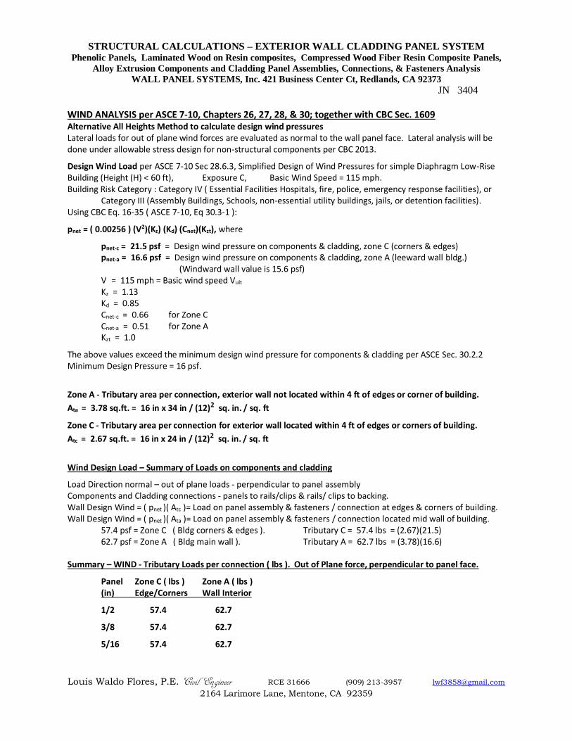
WIND ANALYSIS per ASCE 7-10, Chapters 26, 27, 28, & 30; together with CBC Sec. 1609 Alternative All Heights Method to calculate design wind pressures Lateral loads for out of plane wind forces are evaluated as normal to the wall panel face. Lateral analysis will be done under allowable stress design for non-structural components per CBC 2013.
Design Wind Load per ASCE 7-10 Sec 28.6.3, Simplified Design of Wind Pressures for simple Diaphragm Low-Rise Building (Height (H) < 60 ft), Exposure C, Basic Wind Speed = 115 mph. Building Risk Category : Category IV ( Essential Facilities Hospitals, fire, police, emergency response facilities), or
Category III (Assembly Buildings, Schools, non-essential utility buildings, jails, or detention facilities). Using CBC Eq. 16-35 ( ASCE 7-10, Eq 30.3-1 ):
pnet = ( 0.00256 ) (V2)(Kz) (Kd) (Cnet)(Kzt), where
pnet-c = 21.5 psf = Design wind pressure on components & cladding, zone C (corners & edges) pnet-a = 16.6 psf = Design wind pressure on components & cladding, zone A (leeward wall bldg.) (Windward wall value is 15.6 psf) V = 115 mph = Basic wind speed Vult
Kz = 1.13 Kd = 0.85 Cnet-c = 0.66 for Zone C Cnet-a = 0.51 for Zone A Kzt = 1.0
The above values exceed the minimum design wind pressure for components & cladding per ASCE Sec. 30.2.2 Minimum Design Pressure = 16 psf.
Zone A - Tributary area per connection, exterior wall not located within 4 ft of edges or corner of building.
Ata = 3.78 sq.ft. = 16 in x 34 in / (12)2 sq. in. / sq. ft
Zone C - Tributary area per connection for exterior wall located within 4 ft of edges or corners of building.
Atc = 2.67 sq.ft. = 16 in x 24 in / (12)2 sq. in. / sq. ft
Wind Design Load – Summary of Loads on components and cladding
Load Direction normal – out of plane loads - perpendicular to panel assembly Components and Cladding connections - panels to rails/clips & rails/ clips to backing. Wall Design Wind = ( pnet )( Atc )= Load on panel assembly & fasteners / connection at edges & corners of building. Wall Design Wind = ( pnet )( Ata )= Load on panel assembly & fasteners / connection located mid wall of building.
57.4 psf = Zone C ( Bldg corners & edges ). Tributary C = 57.4 lbs = (2.67)(21.5) 62.7 psf = Zone A ( Bldg main wall ). Tributary A = 62.7 lbs = (3.78)(16.6)
Summary – WIND - Tributary Loads per connection ( lbs ). Out of Plane force, perpendicular to panel face.
Panel Zone C ( lbs ) Zone A ( lbs ) (in) Edge/Corners Wall Interior
1/2 57.4 62.7
3/8 57.4 62.7
5/16 57.4 62.7
STRUCTURAL CALCULATIONS – EXTERIOR WALL CLADDING PANEL SYSTEM Phenolic Panels, Laminated Wood on Resin composites, Compressed Wood Fiber Resin Composite Panels,
Alloy Extrusion Components and Cladding Panel Assemblies, Connections, & Fasteners Analysis
WALL PANEL SYSTEMS, Inc. 421 Business Center Ct, Redlands, CA 92373
JN 3404
Louis Waldo Flores, P.E. Civil Engineer RCE 31666 (909) 213-3957 [email protected]
2164 Larimore Lane, Mentone, CA 92359
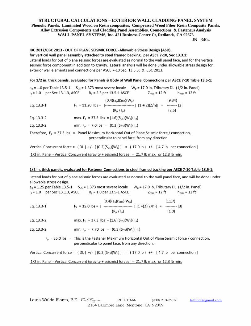
IBC 2012/CBC 2013 - OUT OF PLANE SEISMIC FORCE -Allowable Stress Design (ASD), for vertical wall panel assembly attached to steel framed backing, per ASCE 7-10, Sec 13.3.1: Lateral loads for out of plane seismic forces are evaluated as normal to the wall panel face, and for the vertical seismic force component in addition to gravity. Lateral analysis will be done under allowable stress design for exterior wall elements and connections per ASCE 7-10 Sec. 13.5.3; & CBC 2013. For 1/2 in. thick panels, evaluated for Panels & Body of Wall Panel Connections per ASCE 7-10 Table 13.5-1:
ap = 1.0 per Table 13.5-1 SDS = 1.373 most severe locale Wp = 17.0 lb, Tributary DL (1/2 in. Panel) Ip = 1.0 per Sec.13.1.3, ASCE Rp = 2.5 per 13.5-1 ASCE Zmax = 12 ft hmax = 12 ft
(0.4)(ap)(SDS)(Wp) (9.34) Eq. 13.3-1 Fp = 11.20 lbs = [----------------------- ] [1 +(2)(Z/h)] = -------- [3] (Rp / Ip) (2.5)
Eq. 13.3-2 max. Fp = 37.3 lbs = (1.6)(SDS)(Wp)( Ip)
Eq. 13.3-2 min. Fp = 7.0 lbs = (0.3)(SDS)(Wp)( Ip)
Therefore, Fp = 37.3 lbs = Panel Maximum Horizontal Out of Plane Seismic force / connection, perpendicular to panel face, from any direction.
Vertical Concurrent force = ( DL ) +/- [ (0.2)(SDS)(Wp) ] = ( 17.0 lb ) +/- [ 4.7 lb per connection ]
1/2 in. Panel - Vertical Concurrent (gravity + seismic) forces = 21.7 lb max, or 12.3 lb min. 1/2 in. thick panels, evaluated for Fastener Connections to steel framed backing per ASCE 7-10 Table 13.5-1:
Lateral loads for out of plane seismic forces are evaluated as normal to the wall panel face, and will be done under allowable stress design. ap = 1.25 per Table 13.5-1 SDS = 1.373 most severe locale Wp = 17.0 lb, Tributary DL (1/2 in. Panel) Ip = 1.0 per Sec.13.1.3, ASCE Rp = 1.0 per 13.5-1 ASCE Zmax = 12 ft hmax = 12 ft
(0.4)(ap)(SDS)(Wp) (11.7) Eq. 13.3-1 Fp = 35.0 lbs = [ ----------------------- ] [1 +(2)(Z/h)] = --------- [3] (Rp / Ip) (1.0)
Eq. 13.3-2 max. Fp = 37.3 lbs = (1.6)(SDS)(Wp)( Ip)
Eq. 13.3-2 min. Fp = 7.70 lbs = (0.3)(SDS)(Wp)( Ip)
Fp = 35.0 lbs = This is the Fastener Maximum Horizontal Out of Plane Seismic force / connection, perpendicular to panel face, from any direction.
Vertical Concurrent force = ( DL ) +/- [ (0.2)(SDS)(Wp) ] = ( 17.0 lb ) +/- [ 4.7 lb per connection ]
1/2 in. Panel - Vertical Concurrent (gravity + seismic) forces = 21.7 lb max, or 12.3 lb min.
STRUCTURAL CALCULATIONS – EXTERIOR WALL CLADDING PANEL SYSTEM Phenolic Panels, Laminated Wood on Resin composites, Compressed Wood Fiber Resin Composite Panels,
Alloy Extrusion Components and Cladding Panel Assemblies, Connections, & Fasteners Analysis
WALL PANEL SYSTEMS, Inc. 421 Business Center Ct, Redlands, CA 92373
JN 3404
Louis Waldo Flores, P.E. Civil Engineer RCE 31666 (909) 213-3957 [email protected]
2164 Larimore Lane, Mentone, CA 92359
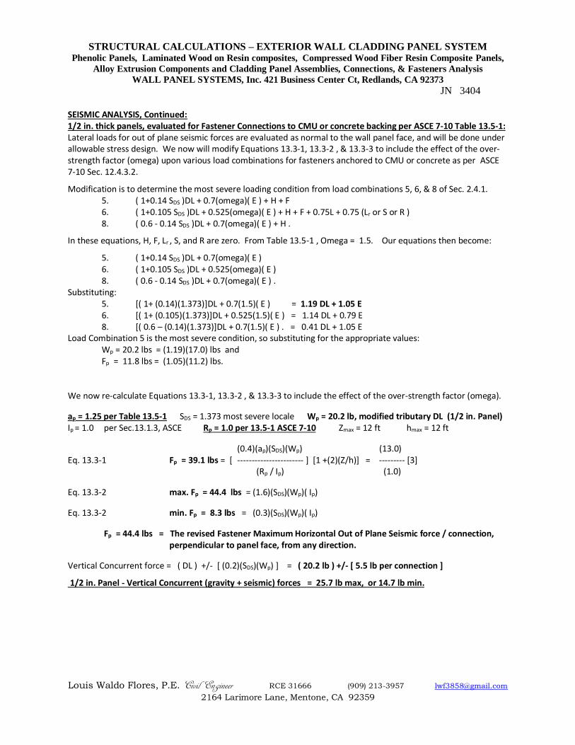
SEISMIC ANALYSIS, Continued: 1/2 in. thick panels, evaluated for Fastener Connections to CMU or concrete backing per ASCE 7-10 Table 13.5-1: Lateral loads for out of plane seismic forces are evaluated as normal to the wall panel face, and will be done under allowable stress design. We now will modify Equations 13.3-1, 13.3-2 , & 13.3-3 to include the effect of the over-strength factor (omega) upon various load combinations for fasteners anchored to CMU or concrete as per ASCE 7-10 Sec. 12.4.3.2.
Modification is to determine the most severe loading condition from load combinations 5, 6, & 8 of Sec. 2.4.1. 5. ( 1+0.14 SDS )DL + 0.7(omega)( E ) + H + F 6. ( 1+0.105 SDS )DL + 0.525(omega)( E ) + H + F + 0.75L + 0.75 (Lr or S or R ) 8. ( 0.6 - 0.14 SDS )DL + 0.7(omega)( E ) + H .
In these equations, H, F, Lr , S, and R are zero. From Table 13.5-1 , Omega = 1.5. Our equations then become:
5. ( 1+0.14 SDS )DL + 0.7(omega)( E ) 6. ( 1+0.105 SDS )DL + 0.525(omega)( E ) 8. ( 0.6 - 0.14 SDS )DL + 0.7(omega)( E ) . Substituting:
5. [( 1+ (0.14)(1.373)]DL + 0.7(1.5)( E ) = 1.19 DL + 1.05 E 6. [( 1+ (0.105)(1.373)]DL + 0.525(1.5)( E ) = 1.14 DL + 0.79 E 8. [( 0.6 – (0.14)(1.373)]DL + 0.7(1.5)( E ) . = 0.41 DL + 1.05 E Load Combination 5 is the most severe condition, so substituting for the appropriate values: Wp = 20.2 lbs = (1.19)(17.0) lbs and
Fp = 11.8 lbs = (1.05)(11.2) lbs.
We now re-calculate Equations 13.3-1, 13.3-2 , & 13.3-3 to include the effect of the over-strength factor (omega).
ap = 1.25 per Table 13.5-1 SDS = 1.373 most severe locale Wp = 20.2 lb, modified tributary DL (1/2 in. Panel) Ip = 1.0 per Sec.13.1.3, ASCE Rp = 1.0 per 13.5-1 ASCE 7-10 Zmax = 12 ft hmax = 12 ft
(0.4)(ap)(SDS)(Wp) (13.0) Eq. 13.3-1 Fp = 39.1 lbs = [ ----------------------- ] [1 +(2)(Z/h)] = --------- [3] (Rp / Ip) (1.0)
Eq. 13.3-2 max. Fp = 44.4 lbs = (1.6)(SDS)(Wp)( Ip)
Eq. 13.3-2 min. Fp = 8.3 lbs = (0.3)(SDS)(Wp)( Ip)
Fp = 44.4 lbs = The revised Fastener Maximum Horizontal Out of Plane Seismic force / connection, perpendicular to panel face, from any direction.
Vertical Concurrent force = ( DL ) +/- [ (0.2)(SDS)(Wp) ] = ( 20.2 lb ) +/- [ 5.5 lb per connection ]
1/2 in. Panel - Vertical Concurrent (gravity + seismic) forces = 25.7 lb max, or 14.7 lb min.
STRUCTURAL CALCULATIONS – EXTERIOR WALL CLADDING PANEL SYSTEM Phenolic Panels, Laminated Wood on Resin composites, Compressed Wood Fiber Resin Composite Panels,
Alloy Extrusion Components and Cladding Panel Assemblies, Connections, & Fasteners Analysis
WALL PANEL SYSTEMS, Inc. 421 Business Center Ct, Redlands, CA 92373
JN 3404
Louis Waldo Flores, P.E. Civil Engineer RCE 31666 (909) 213-3957 [email protected]
2164 Larimore Lane, Mentone, CA 92359
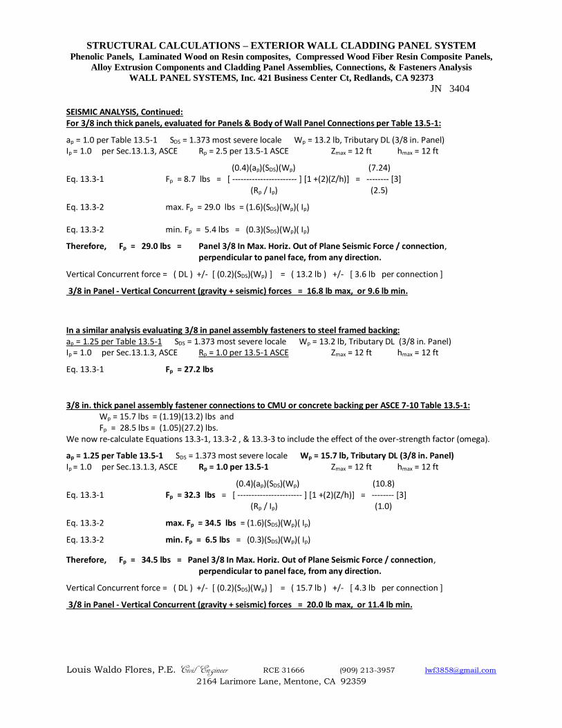
SEISMIC ANALYSIS, Continued: For 3/8 inch thick panels, evaluated for Panels & Body of Wall Panel Connections per Table 13.5-1:
ap = 1.0 per Table 13.5-1 SDS = 1.373 most severe locale Wp = 13.2 lb, Tributary DL (3/8 in. Panel) Ip = 1.0 per Sec.13.1.3, ASCE Rp = 2.5 per 13.5-1 ASCE Zmax = 12 ft hmax = 12 ft
(0.4)(ap)(SDS)(Wp) (7.24) Eq. 13.3-1 Fp = 8.7 lbs = [ ----------------------- ] [1 +(2)(Z/h)] = -------- [3] (Rp / Ip) (2.5)
Eq. 13.3-2 max. Fp = 29.0 lbs = (1.6)(SDS)(Wp)( Ip) Eq. 13.3-2 min. Fp = 5.4 lbs = (0.3)(SDS)(Wp)( Ip)
Therefore, Fp = 29.0 lbs = Panel 3/8 In Max. Horiz. Out of Plane Seismic Force / connection, perpendicular to panel face, from any direction.
Vertical Concurrent force = ( DL ) +/- [ (0.2)(SDS)(Wp) ] = ( 13.2 lb ) +/- [ 3.6 lb per connection ]
3/8 in Panel - Vertical Concurrent (gravity + seismic) forces = 16.8 lb max, or 9.6 lb min.
In a similar analysis evaluating 3/8 in panel assembly fasteners to steel framed backing: ap = 1.25 per Table 13.5-1 SDS = 1.373 most severe locale Wp = 13.2 lb, Tributary DL (3/8 in. Panel) Ip = 1.0 per Sec.13.1.3, ASCE Rp = 1.0 per 13.5-1 ASCE Zmax = 12 ft hmax = 12 ft
Eq. 13.3-1 Fp = 27.2 lbs 3/8 in. thick panel assembly fastener connections to CMU or concrete backing per ASCE 7-10 Table 13.5-1: Wp = 15.7 lbs = (1.19)(13.2) lbs and
Fp = 28.5 lbs = (1.05)(27.2) lbs. We now re-calculate Equations 13.3-1, 13.3-2 , & 13.3-3 to include the effect of the over-strength factor (omega).
ap = 1.25 per Table 13.5-1 SDS = 1.373 most severe locale Wp = 15.7 lb, Tributary DL (3/8 in. Panel) Ip = 1.0 per Sec.13.1.3, ASCE Rp = 1.0 per 13.5-1 Zmax = 12 ft hmax = 12 ft
(0.4)(ap)(SDS)(Wp) (10.8) Eq. 13.3-1 Fp = 32.3 lbs = [ ----------------------- ] [1 +(2)(Z/h)] = -------- [3] (Rp / Ip) (1.0)
Eq. 13.3-2 max. Fp = 34.5 lbs = (1.6)(SDS)(Wp)( Ip)
Eq. 13.3-2 min. Fp = 6.5 lbs = (0.3)(SDS)(Wp)( Ip)
Therefore, Fp = 34.5 lbs = Panel 3/8 In Max. Horiz. Out of Plane Seismic Force / connection, perpendicular to panel face, from any direction.
Vertical Concurrent force = ( DL ) +/- [ (0.2)(SDS)(Wp) ] = ( 15.7 lb ) +/- [ 4.3 lb per connection ]
3/8 in Panel - Vertical Concurrent (gravity + seismic) forces = 20.0 lb max, or 11.4 lb min.
STRUCTURAL CALCULATIONS – EXTERIOR WALL CLADDING PANEL SYSTEM Phenolic Panels, Laminated Wood on Resin composites, Compressed Wood Fiber Resin Composite Panels,
Alloy Extrusion Components and Cladding Panel Assemblies, Connections, & Fasteners Analysis
WALL PANEL SYSTEMS, Inc. 421 Business Center Ct, Redlands, CA 92373
JN 3404
Louis Waldo Flores, P.E. Civil Engineer RCE 31666 (909) 213-3957 [email protected]
2164 Larimore Lane, Mentone, CA 92359
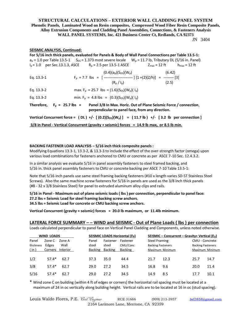
SEISMIC ANALYSIS, Continued: For 5/16 inch thick panels, evaluated for Panels & Body of Wall Panel Connections per Table 13.5-1: ap = 1.0 per Table 13.5-1 SDS = 1.373 most severe locale Wp = 11.7 lb, Tributary DL (5/16 in. Panel) Ip = 1.0 per Sec.13.1.3, ASCE Rp = 2.5 per 13.5-1 ASCE Zmax = 12 ft hmax = 12 ft
(0.4)(ap)(SDS)(Wp) (6.42) Eq. 13.3-1 Fp = 7.7 lbs = [ ----------------------- ] [1 +(2)(Z/h)] = -------- [3] (Rp / Ip) (2.5)
Eq. 13.3-2 max. Fp = 25.7 lbs = (1.6)(SDS)(Wp)( Ip)
Eq. 13.3-2 min. Fp = 4.8 lbs = (0.3)(SDS)(Wp)( Ip)
Therefore, Fp = 25.7 lbs = Panel 3/8 In Max. Horiz. Out of Plane Seismic Force / connection, perpendicular to panel face, from any direction.
Vertical Concurrent force = ( DL ) +/- [ (0.2)(SDS)(Wp) ] = ( 11.7 lb ) +/- [ 3.2 lb per connection ]
3/8 in Panel - Vertical Concurrent (gravity + seismic) forces = 14.9 lb max, or 8.5 lb min.
BACKING FASTENER LOAD ANALYSIS – 5/16 inch thick composite panels : Modifying Equations 13.3-1, 13.3-2, & 13.3-3 to include the effect of the over-strength factor (omega) upon various load combinations for fasteners anchored to CMU or concrete as per ASCE 7-10 Sec. 12.4.3.2.
In a similar analysis we evaluate 5/16 in panel assembly fasteners to steel framed backing, and 5/16 in. thick panel assembly fasteners to CMU or concrete backing per ASCE 7-10 Table 13.5-1:
Note that 5/16 inch panels use same steel framing backing fasteners (#10 x length varies SD-ST Stainless Steel Screws). Also the same machine screw fasteners for 5/16 in panels are used as the 3/8 inch thick panels (#8 - 32 x 3/8 Stainless Steel) for panel to extruded aluminum alloy clips and rails.
5/16 in Panel - Maximum out of plane seismic loads ( lbs ) per connection, perpendicular to panel face: 27.2 lbs = Seismic Load for steel framing backing screw anchors. 34.5 lbs = Seismic Load for concrete or CMU backing screw anchors.
Vertical Concurrent (gravity + seismic) forces = 20.0 lb maximum, or 11.4lb minimum.
LATERAL FORCE SUMMARY – – WIND and SEISMIC - Out of Plane Loads ( lbs ) per connection Loads calculated perpendicular to panel face on Vertical Panel Cladding and Components, unless noted otherwise.
WIND LOADS SEISMIC LOADS Horizontal (FP) SEISMIC – Concurrent – Gravity+ Vertical (EV)
Panel Zone C Zone A Panel Fastener Fastener Steel Framing CMU - Concrete thickness Edges Wall steel steel CMU/Conc Backing Fasteners Backing Fasteners
( in ) Corners Interior Backing Backing Backing Maximum Minimum Maximum Minimum
1/2 57.4* 62.7 37.3 35.0 44.4 21.7 12.3 25.7 14.7
3/8 57.4* 62.7 29.0 27.2 34.5 16.8 9.6 20.0 11.4
5/16 57.4* 62.7 29.0 27.2 34.5 14.9 8.5 17.7 10.1
* Wind zone C on building (within 4 ft of edges or corners) the horizontal rail spacing must be located at a maximum of 24 in oc vertically along building height. Vertical rails are to be located at 16 in oc (stud spacing).
STRUCTURAL CALCULATIONS – EXTERIOR WALL CLADDING PANEL SYSTEM Phenolic Panels, Laminated Wood on Resin composites, Compressed Wood Fiber Resin Composite Panels,
Alloy Extrusion Components and Cladding Panel Assemblies, Connections, & Fasteners Analysis
WALL PANEL SYSTEMS, Inc. 421 Business Center Ct, Redlands, CA 92373
JN 3404
Louis Waldo Flores, P.E. Civil Engineer RCE 31666 (909) 213-3957 [email protected]
2164 Larimore Lane, Mentone, CA 92359
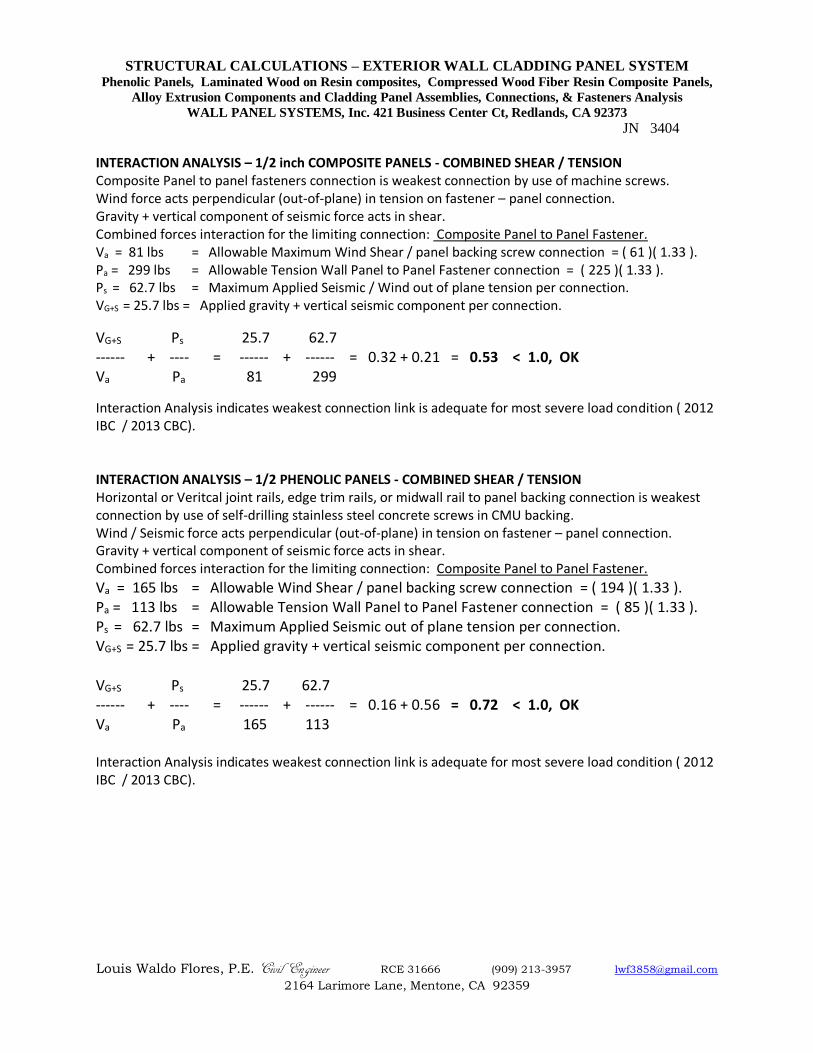
INTERACTION ANALYSIS – 1/2 inch COMPOSITE PANELS - COMBINED SHEAR / TENSION Composite Panel to panel fasteners connection is weakest connection by use of machine screws. Wind force acts perpendicular (out-of-plane) in tension on fastener – panel connection. Gravity + vertical component of seismic force acts in shear. Combined forces interaction for the limiting connection: Composite Panel to Panel Fastener. Va = 81 lbs = Allowable Maximum Wind Shear / panel backing screw connection = ( 61 )( 1.33 ). Pa = 299 lbs = Allowable Tension Wall Panel to Panel Fastener connection = ( 225 )( 1.33 ). Ps = 62.7 lbs = Maximum Applied Seismic / Wind out of plane tension per connection. VG+S = 25.7 lbs = Applied gravity + vertical seismic component per connection.
VG+S Ps 25.7 62.7 ------ + ---- = ------ + ------ = 0.32 + 0.21 = 0.53 < 1.0, OK Va Pa 81 299
Interaction Analysis indicates weakest connection link is adequate for most severe load condition ( 2012 IBC / 2013 CBC). INTERACTION ANALYSIS – 1/2 PHENOLIC PANELS - COMBINED SHEAR / TENSION Horizontal or Veritcal joint rails, edge trim rails, or midwall rail to panel backing connection is weakest connection by use of self-drilling stainless steel concrete screws in CMU backing. Wind / Seismic force acts perpendicular (out-of-plane) in tension on fastener – panel connection. Gravity + vertical component of seismic force acts in shear. Combined forces interaction for the limiting connection: Composite Panel to Panel Fastener.
Va = 165 lbs = Allowable Wind Shear / panel backing screw connection = ( 194 )( 1.33 ). Pa = 113 lbs = Allowable Tension Wall Panel to Panel Fastener connection = ( 85 )( 1.33 ). Ps = 62.7 lbs = Maximum Applied Seismic out of plane tension per connection. VG+S = 25.7 lbs = Applied gravity + vertical seismic component per connection. VG+S Ps 25.7 62.7 ------ + ---- = ------ + ------ = 0.16 + 0.56 = 0.72 < 1.0, OK Va Pa 165 113 Interaction Analysis indicates weakest connection link is adequate for most severe load condition ( 2012 IBC / 2013 CBC).
STRUCTURAL CALCULATIONS – EXTERIOR WALL CLADDING PANEL SYSTEM Phenolic Panels, Laminated Wood on Resin composites, Compressed Wood Fiber Resin Composite Panels,
Alloy Extrusion Components and Cladding Panel Assemblies, Connections, & Fasteners Analysis
WALL PANEL SYSTEMS, Inc. 421 Business Center Ct, Redlands, CA 92373
JN 3404
Louis Waldo Flores, P.E. Civil Engineer RCE 31666 (909) 213-3957 [email protected]
2164 Larimore Lane, Mentone, CA 92359
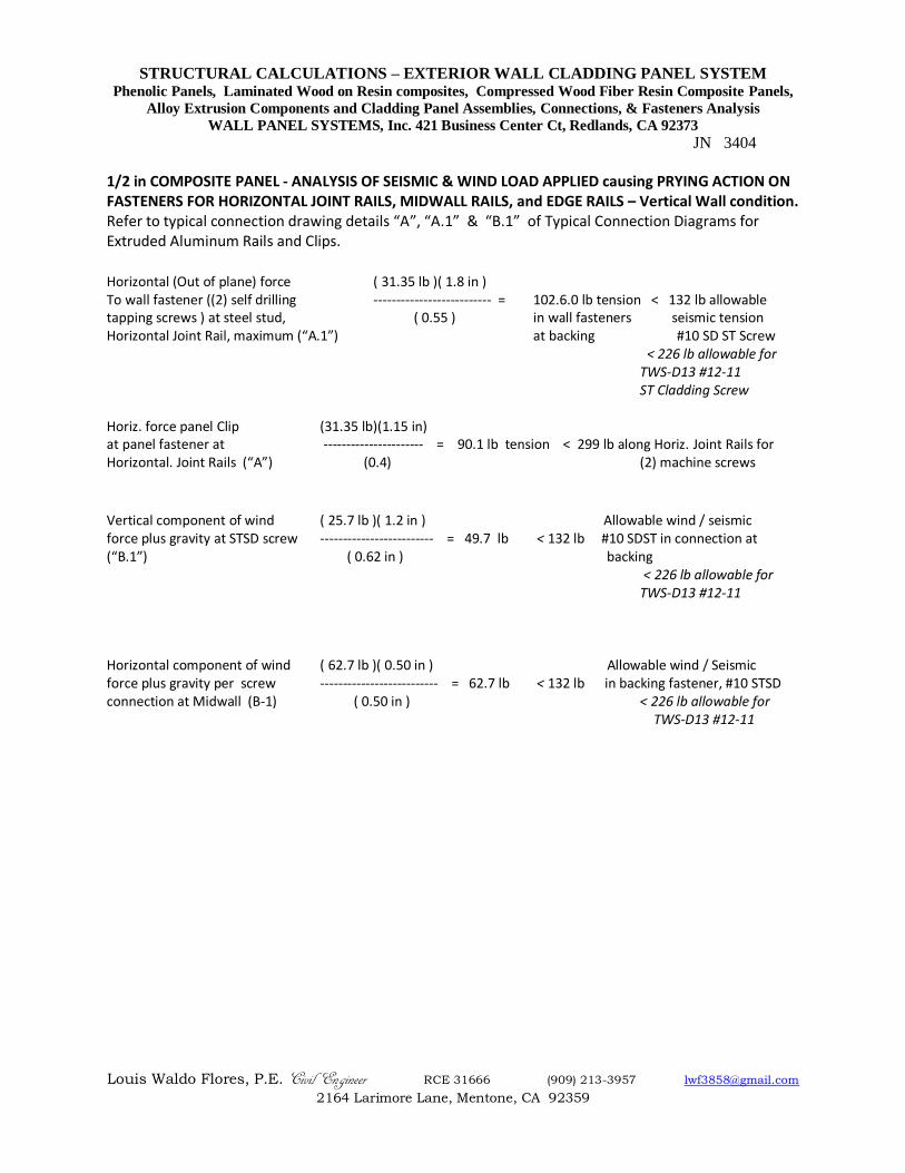
1/2 in COMPOSITE PANEL - ANALYSIS OF SEISMIC & WIND LOAD APPLIED causing PRYING ACTION ON FASTENERS FOR HORIZONTAL JOINT RAILS, MIDWALL RAILS, and EDGE RAILS – Vertical Wall condition. Refer to typical connection drawing details “A”, “A.1” & “B.1” of Typical Connection Diagrams for Extruded Aluminum Rails and Clips.
Horizontal (Out of plane) force ( 31.35 lb )( 1.8 in ) To wall fastener ((2) self drilling -------------------------- = 102.6.0 lb tension < 132 lb allowable tapping screws ) at steel stud, ( 0.55 ) in wall fasteners seismic tension Horizontal Joint Rail, maximum (“A.1”) at backing #10 SD ST Screw
< 226 lb allowable for TWS-D13 #12-11 ST Cladding Screw
Horiz. force panel Clip (31.35 lb)(1.15 in) at panel fastener at ---------------------- = 90.1 lb tension < 299 lb along Horiz. Joint Rails for Horizontal. Joint Rails (“A”) (0.4) (2) machine screws
Vertical component of wind ( 25.7 lb )( 1.2 in ) Allowable wind / seismic force plus gravity at STSD screw ------------------------- = 49.7 lb < 132 lb #10 SDST in connection at (“B.1”) ( 0.62 in ) backing
< 226 lb allowable for TWS-D13 #12-11
Horizontal component of wind ( 62.7 lb )( 0.50 in ) Allowable wind / Seismic force plus gravity per screw -------------------------- = 62.7 lb < 132 lb in backing fastener, #10 STSD connection at Midwall (B-1) ( 0.50 in ) < 226 lb allowable for
TWS-D13 #12-11
STRUCTURAL CALCULATIONS – EXTERIOR WALL CLADDING PANEL SYSTEM Phenolic Panels, Laminated Wood on Resin composites, Compressed Wood Fiber Resin Composite Panels,
Alloy Extrusion Components and Cladding Panel Assemblies, Connections, & Fasteners Analysis
WALL PANEL SYSTEMS, Inc. 421 Business Center Ct, Redlands, CA 92373
JN 3404
Louis Waldo Flores, P.E. Civil Engineer RCE 31666 (909) 213-3957 [email protected]
2164 Larimore Lane, Mentone, CA 92359
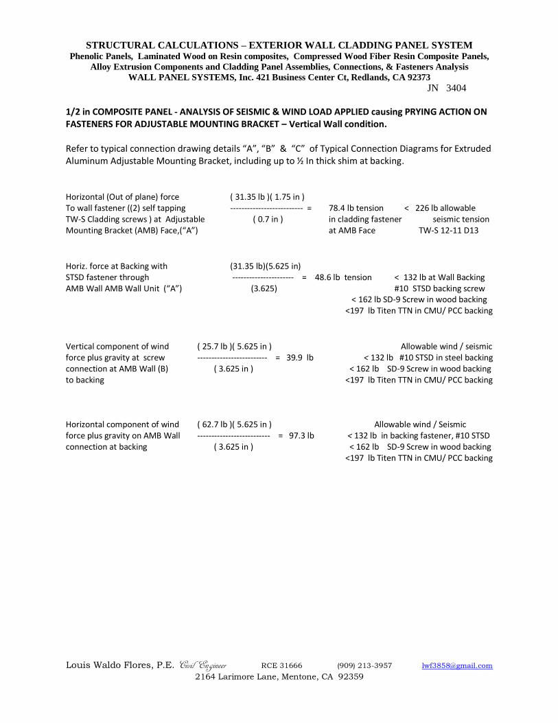
1/2 in COMPOSITE PANEL - ANALYSIS OF SEISMIC & WIND LOAD APPLIED causing PRYING ACTION ON FASTENERS FOR ADJUSTABLE MOUNTING BRACKET – Vertical Wall condition. Refer to typical connection drawing details “A”, “B” & “C” of Typical Connection Diagrams for Extruded Aluminum Adjustable Mounting Bracket, including up to ½ In thick shim at backing.
Horizontal (Out of plane) force ( 31.35 lb )( 1.75 in ) To wall fastener ((2) self tapping -------------------------- = 78.4 lb tension < 226 lb allowable TW-S Cladding screws ) at Adjustable ( 0.7 in ) in cladding fastener seismic tension Mounting Bracket (AMB) Face,(“A”) at AMB Face TW-S 12-11 D13
Horiz. force at Backing with (31.35 lb)(5.625 in) STSD fastener through ---------------------- = 48.6 lb tension < 132 lb at Wall Backing AMB Wall AMB Wall Unit (“A”) (3.625) #10 STSD backing screw < 162 lb SD-9 Screw in wood backing <197 lb Titen TTN in CMU/ PCC backing
Vertical component of wind ( 25.7 lb )( 5.625 in ) Allowable wind / seismic force plus gravity at screw ------------------------- = 39.9 lb < 132 lb #10 STSD in steel backing connection at AMB Wall (B) ( 3.625 in ) < 162 lb SD-9 Screw in wood backing to backing <197 lb Titen TTN in CMU/ PCC backing Horizontal component of wind ( 62.7 lb )( 5.625 in ) Allowable wind / Seismic force plus gravity on AMB Wall -------------------------- = 97.3 lb < 132 lb in backing fastener, #10 STSD connection at backing ( 3.625 in ) < 162 lb SD-9 Screw in wood backing <197 lb Titen TTN in CMU/ PCC backing
STRUCTURAL CALCULATIONS – EXTERIOR WALL CLADDING PANEL SYSTEM Phenolic Panels, Laminated Wood on Resin composites, Compressed Wood Fiber Resin Composite Panels,
Alloy Extrusion Components and Cladding Panel Assemblies, Connections, & Fasteners Analysis
WALL PANEL SYSTEMS, Inc. 421 Business Center Ct, Redlands, CA 92373
JN 3404
Louis Waldo Flores, P.E. Civil Engineer RCE 31666 (909) 213-3957 [email protected]
2164 Larimore Lane, Mentone, CA 92359
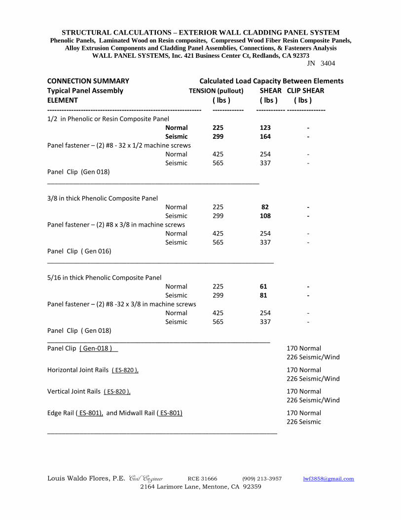
CONNECTION SUMMARY Calculated Load Capacity Between Elements Typical Panel Assembly TENSION (pullout) SHEAR CLIP SHEAR ELEMENT ( lbs ) ( lbs ) ( lbs ) ---------------------------------------------------------------- ------------- ------------ ---------------- 1/2 in Phenolic or Resin Composite Panel Normal 225 123 - Seismic 299 164 - Panel fastener – (2) #8 - 32 x 1/2 machine screws Normal 425 254 - Seismic 565 337 - Panel Clip (Gen 018) ___________________________________________________________ 3/8 in thick Phenolic Composite Panel Normal 225 82 - Seismic 299 108 - Panel fastener – (2) #8 x 3/8 in machine screws Normal 425 254 - Seismic 565 337 - Panel Clip ( Gen 016) _______________________________________________________________ 5/16 in thick Phenolic Composite Panel Normal 225 61 - Seismic 299 81 - Panel fastener – (2) #8 -32 x 3/8 in machine screws Normal 425 254 - Seismic 565 337 - Panel Clip ( Gen 018) ______________________________________________________________ Panel Clip ( Gen-018 ) 170 Normal 226 Seismic/Wind
Horizontal Joint Rails ( ES-820 ), 170 Normal 226 Seismic/Wind
Vertical Joint Rails ( ES-820 ), 170 Normal 226 Seismic/Wind
Edge Rail ( ES-801), and Midwall Rail ( ES-801) 170 Normal 226 Seismic
________________________________________________________________
STRUCTURAL CALCULATIONS – EXTERIOR WALL CLADDING PANEL SYSTEM Phenolic Panels, Laminated Wood on Resin composites, Compressed Wood Fiber Resin Composite Panels,
Alloy Extrusion Components and Cladding Panel Assemblies, Connections, & Fasteners Analysis
WALL PANEL SYSTEMS, Inc. 421 Business Center Ct, Redlands, CA 92373
JN 3404
Louis Waldo Flores, P.E. Civil Engineer RCE 31666 (909) 213-3957 [email protected]
2164 Larimore Lane, Mentone, CA 92359
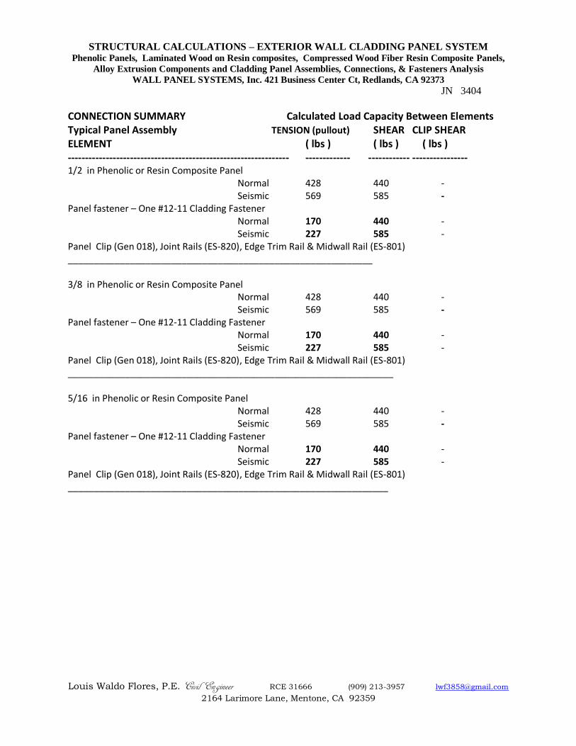
CONNECTION SUMMARY Calculated Load Capacity Between Elements Typical Panel Assembly TENSION (pullout) SHEAR CLIP SHEAR ELEMENT ( lbs ) ( lbs ) ( lbs ) ---------------------------------------------------------------- ------------- ------------ ---------------- 1/2 in Phenolic or Resin Composite Panel Normal 428 440 - Seismic 569 585 - Panel fastener – One #12-11 Cladding Fastener Normal 170 440 - Seismic 227 585 - Panel Clip (Gen 018), Joint Rails (ES-820), Edge Trim Rail & Midwall Rail (ES-801) ___________________________________________________________ 3/8 in Phenolic or Resin Composite Panel Normal 428 440 - Seismic 569 585 - Panel fastener – One #12-11 Cladding Fastener Normal 170 440 - Seismic 227 585 - Panel Clip (Gen 018), Joint Rails (ES-820), Edge Trim Rail & Midwall Rail (ES-801) _______________________________________________________________ 5/16 in Phenolic or Resin Composite Panel Normal 428 440 - Seismic 569 585 - Panel fastener – One #12-11 Cladding Fastener Normal 170 440 - Seismic 227 585 - Panel Clip (Gen 018), Joint Rails (ES-820), Edge Trim Rail & Midwall Rail (ES-801) ______________________________________________________________
STRUCTURAL CALCULATIONS – EXTERIOR WALL CLADDING PANEL SYSTEM Phenolic Panels, Laminated Wood on Resin composites, Compressed Wood Fiber Resin Composite Panels,
Alloy Extrusion Components and Cladding Panel Assemblies, Connections, & Fasteners Analysis
WALL PANEL SYSTEMS, Inc. 421 Business Center Ct, Redlands, CA 92373
JN 3404
Louis Waldo Flores, P.E. Civil Engineer RCE 31666 (909) 213-3957 [email protected]
2164 Larimore Lane, Mentone, CA 92359
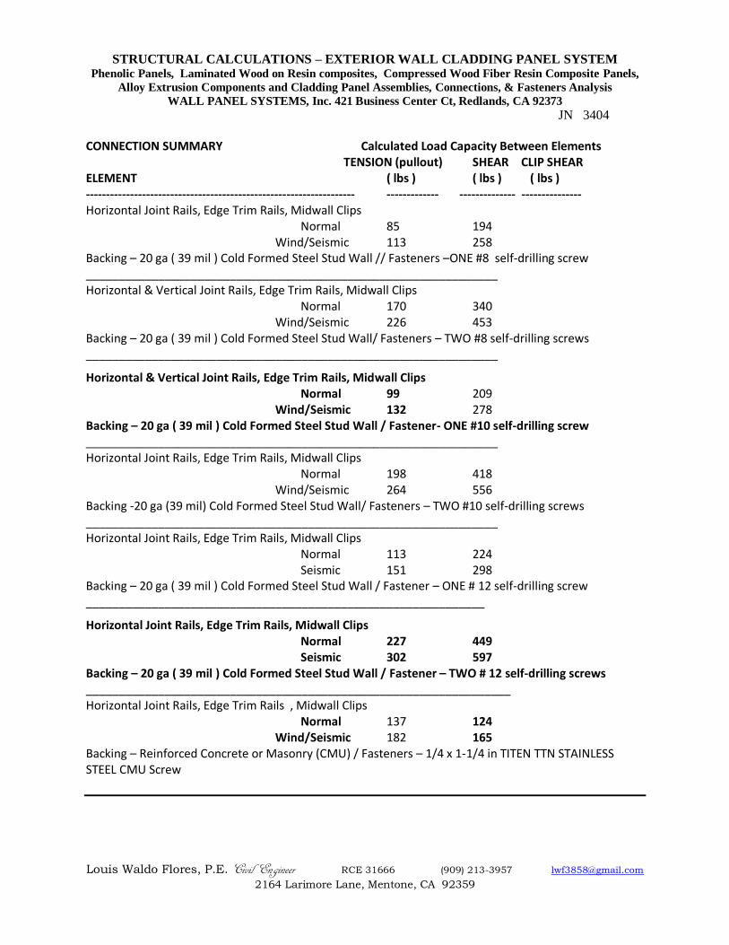
CONNECTION SUMMARY Calculated Load Capacity Between Elements TENSION (pullout) SHEAR CLIP SHEAR ELEMENT ( lbs ) ( lbs ) ( lbs ) ------------------------------------------------------------------- ------------- -------------- --------------- Horizontal Joint Rails, Edge Trim Rails, Midwall Clips Normal 85 194 Wind/Seismic 113 258 Backing – 20 ga ( 39 mil ) Cold Formed Steel Stud Wall // Fasteners –ONE #8 self-drilling screw _______________________________________________________________ Horizontal & Vertical Joint Rails, Edge Trim Rails, Midwall Clips Normal 170 340 Wind/Seismic 226 453 Backing – 20 ga ( 39 mil ) Cold Formed Steel Stud Wall/ Fasteners – TWO #8 self-drilling screws _______________________________________________________________
Horizontal & Vertical Joint Rails, Edge Trim Rails, Midwall Clips Normal 99 209 Wind/Seismic 132 278 Backing – 20 ga ( 39 mil ) Cold Formed Steel Stud Wall / Fastener- ONE #10 self-drilling screw _______________________________________________________________ Horizontal Joint Rails, Edge Trim Rails, Midwall Clips Normal 198 418 Wind/Seismic 264 556 Backing -20 ga (39 mil) Cold Formed Steel Stud Wall/ Fasteners – TWO #10 self-drilling screws _______________________________________________________________ Horizontal Joint Rails, Edge Trim Rails, Midwall Clips Normal 113 224 Seismic 151 298 Backing – 20 ga ( 39 mil ) Cold Formed Steel Stud Wall / Fastener – ONE # 12 self-drilling screw _____________________________________________________________
Horizontal Joint Rails, Edge Trim Rails, Midwall Clips Normal 227 449 Seismic 302 597 Backing – 20 ga ( 39 mil ) Cold Formed Steel Stud Wall / Fastener – TWO # 12 self-drilling screws _________________________________________________________________ Horizontal Joint Rails, Edge Trim Rails , Midwall Clips Normal 137 124 Wind/Seismic 182 165 Backing – Reinforced Concrete or Masonry (CMU) / Fasteners – 1/4 x 1-1/4 in TITEN TTN STAINLESS STEEL CMU Screw
STRUCTURAL CALCULATIONS – EXTERIOR WALL CLADDING PANEL SYSTEM Phenolic Panels, Laminated Wood on Resin composites, Compressed Wood Fiber Resin Composite Panels,
Alloy Extrusion Components and Cladding Panel Assemblies, Connections, & Fasteners Analysis
WALL PANEL SYSTEMS, Inc. 421 Business Center Ct, Redlands, CA 92373
JN 3404
Louis Waldo Flores, P.E. Civil Engineer RCE 31666 (909) 213-3957 [email protected]
2164 Larimore Lane, Mentone, CA 92359
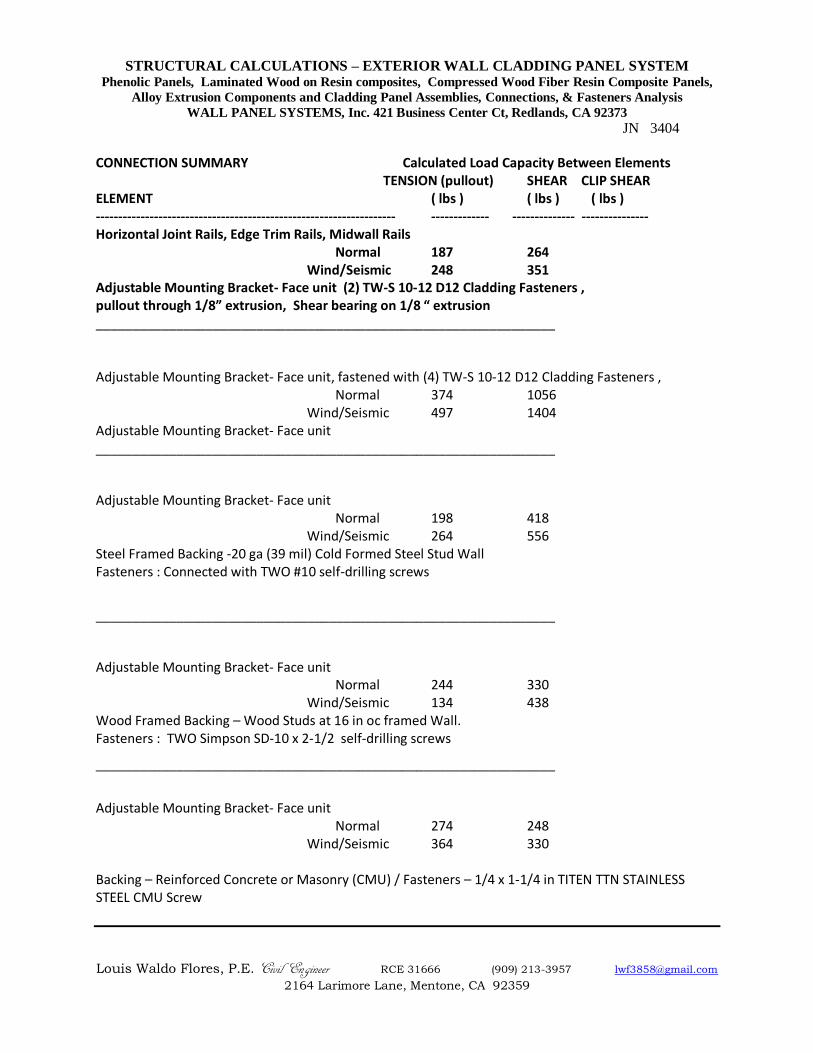
CONNECTION SUMMARY Calculated Load Capacity Between Elements TENSION (pullout) SHEAR CLIP SHEAR ELEMENT ( lbs ) ( lbs ) ( lbs ) ------------------------------------------------------------------- ------------- -------------- --------------- Horizontal Joint Rails, Edge Trim Rails, Midwall Rails Normal 187 264 Wind/Seismic 248 351 Adjustable Mounting Bracket- Face unit (2) TW-S 10-12 D12 Cladding Fasteners , pullout through 1/8” extrusion, Shear bearing on 1/8 “ extrusion _______________________________________________________________ Adjustable Mounting Bracket- Face unit, fastened with (4) TW-S 10-12 D12 Cladding Fasteners , Normal 374 1056 Wind/Seismic 497 1404 Adjustable Mounting Bracket- Face unit _______________________________________________________________
Adjustable Mounting Bracket- Face unit Normal 198 418 Wind/Seismic 264 556 Steel Framed Backing -20 ga (39 mil) Cold Formed Steel Stud Wall Fasteners : Connected with TWO #10 self-drilling screws
_______________________________________________________________
Adjustable Mounting Bracket- Face unit Normal 244 330 Wind/Seismic 134 438 Wood Framed Backing – Wood Studs at 16 in oc framed Wall. Fasteners : TWO Simpson SD-10 x 2-1/2 self-drilling screws
_______________________________________________________________
Adjustable Mounting Bracket- Face unit Normal 274 248 Wind/Seismic 364 330 Backing – Reinforced Concrete or Masonry (CMU) / Fasteners – 1/4 x 1-1/4 in TITEN TTN STAINLESS STEEL CMU Screw
STRUCTURAL CALCULATIONS – EXTERIOR WALL CLADDING PANEL SYSTEM Phenolic Panels, Laminated Wood on Resin composites, Compressed Wood Fiber Resin Composite Panels,
Alloy Extrusion Components and Cladding Panel Assemblies, Connections, & Fasteners Analysis
WALL PANEL SYSTEMS, Inc. 421 Business Center Ct, Redlands, CA 92373
JN 3404
Louis Waldo Flores, P.E. Civil Engineer RCE 31666 (909) 213-3957 [email protected]
2164 Larimore Lane, Mentone, CA 92359
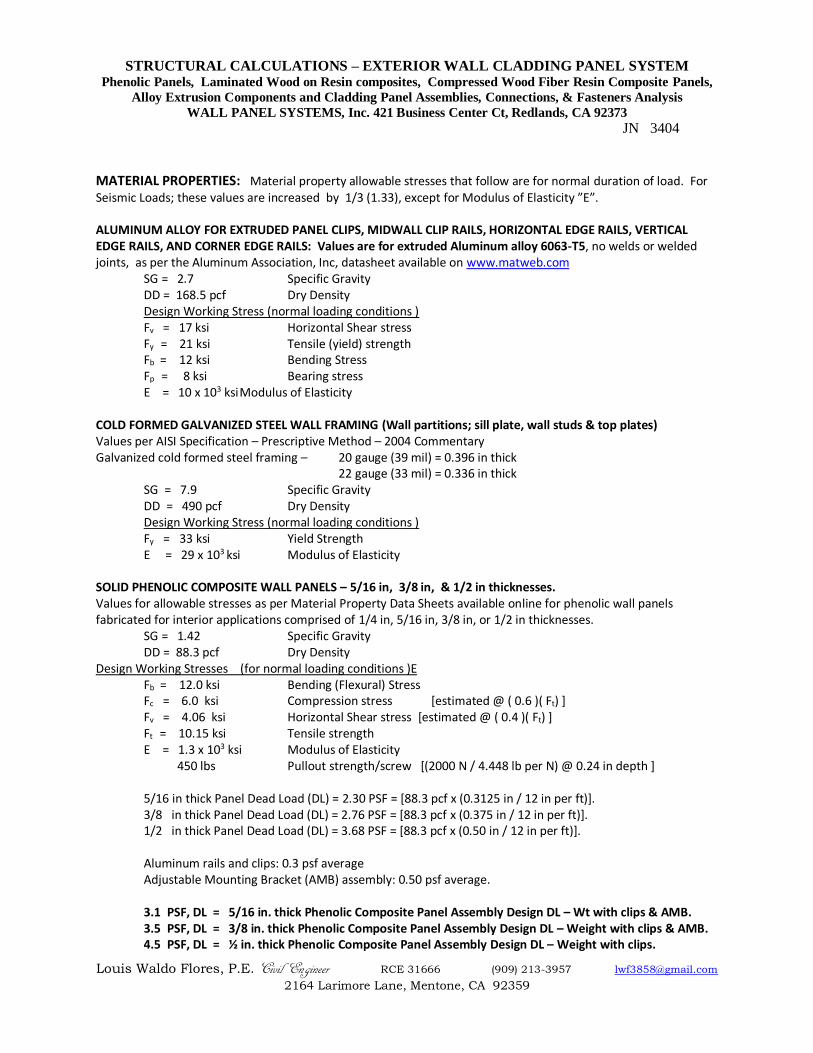
MATERIAL PROPERTIES: Material property allowable stresses that follow are for normal duration of load. For Seismic Loads; these values are increased by 1/3 (1.33), except for Modulus of Elasticity ”E”. ALUMINUM ALLOY FOR EXTRUDED PANEL CLIPS, MIDWALL CLIP RAILS, HORIZONTAL EDGE RAILS, VERTICAL EDGE RAILS, AND CORNER EDGE RAILS: Values are for extruded Aluminum alloy 6063-T5, no welds or welded joints, as per the Aluminum Association, Inc, datasheet available on www.matweb.com
SG = 2.7 Specific Gravity DD = 168.5 pcf Dry Density
Design Working Stress (normal loading conditions ) Fv = 17 ksi Horizontal Shear stress Fy = 21 ksi Tensile (yield) strength Fb = 12 ksi Bending Stress
Fp = 8 ksi Bearing stress E = 10 x 103 ksi Modulus of Elasticity COLD FORMED GALVANIZED STEEL WALL FRAMING (Wall partitions; sill plate, wall studs & top plates) Values per AISI Specification – Prescriptive Method – 2004 Commentary Galvanized cold formed steel framing – 20 gauge (39 mil) = 0.396 in thick
22 gauge (33 mil) = 0.336 in thick SG = 7.9 Specific Gravity DD = 490 pcf Dry Density
Design Working Stress (normal loading conditions ) Fy = 33 ksi Yield Strength E = 29 x 103 ksi Modulus of Elasticity SOLID PHENOLIC COMPOSITE WALL PANELS – 5/16 in, 3/8 in, & 1/2 in thicknesses. Values for allowable stresses as per Material Property Data Sheets available online for phenolic wall panels fabricated for interior applications comprised of 1/4 in, 5/16 in, 3/8 in, or 1/2 in thicknesses.
SG = 1.42 Specific Gravity DD = 88.3 pcf Dry Density Design Working Stresses (for normal loading conditions )E
Fb = 12.0 ksi Bending (Flexural) Stress Fc = 6.0 ksi Compression stress [estimated @ ( 0.6 )( Ft) ] Fv = 4.06 ksi Horizontal Shear stress [estimated @ ( 0.4 )( Ft) ]
Ft = 10.15 ksi Tensile strength E = 1.3 x 10³ ksi Modulus of Elasticity
450 lbs Pullout strength/screw [(2000 N / 4.448 lb per N) @ 0.24 in depth ] 5/16 in thick Panel Dead Load (DL) = 2.30 PSF = [88.3 pcf x (0.3125 in / 12 in per ft)]. 3/8 in thick Panel Dead Load (DL) = 2.76 PSF = [88.3 pcf x (0.375 in / 12 in per ft)]. 1/2 in thick Panel Dead Load (DL) = 3.68 PSF = [88.3 pcf x (0.50 in / 12 in per ft)]. Aluminum rails and clips: 0.3 psf average Adjustable Mounting Bracket (AMB) assembly: 0.50 psf average. 3.1 PSF, DL = 5/16 in. thick Phenolic Composite Panel Assembly Design DL – Wt with clips & AMB. 3.5 PSF, DL = 3/8 in. thick Phenolic Composite Panel Assembly Design DL – Weight with clips & AMB. 4.5 PSF, DL = ½ in. thick Phenolic Composite Panel Assembly Design DL – Weight with clips.
STRUCTURAL CALCULATIONS – EXTERIOR WALL CLADDING PANEL SYSTEM Phenolic Panels, Laminated Wood on Resin composites, Compressed Wood Fiber Resin Composite Panels,
Alloy Extrusion Components and Cladding Panel Assemblies, Connections, & Fasteners Analysis
WALL PANEL SYSTEMS, Inc. 421 Business Center Ct, Redlands, CA 92373
JN 3404
Louis Waldo Flores, P.E. Civil Engineer RCE 31666 (909) 213-3957 [email protected]
2164 Larimore Lane, Mentone, CA 92359
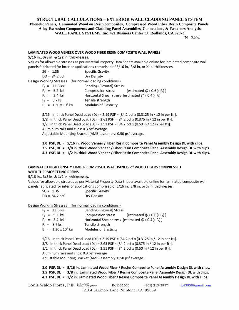
LAMINATED WOOD VENEER OVER WOOD FIBER RESIN COMPOSITE WALL PANELS 5/16 in., 3/8 in. & 1/2 in. thicknesses. Values for allowable stresses as per Material Property Data Sheets available online for laminated composite wall panels fabricated for interior applications comprised of 5/16 in, 3/8 in, or ½ in. thicknesses.
SG = 1.35 Specific Gravity DD = 84.2 pcf Dry Density Design Working Stresses (for normal loading conditions )
Fb = 11.6 ksi Bending (Flexural) Stress Fc = 5.2 ksi Compression stress [estimated @ ( 0.6 )( Ft) ] Fv = 3.4 ksi Horizontal Shear stress [estimated @ ( 0.4 )( Ft) ]
Ft = 8.7 ksi Tensile strength E = 1.30 x 10³ ksi Modulus of Elasticity
5/16 in thick Panel Dead Load (DL) = 2.19 PSF = [84.2 pcf x (0.3125 in / 12 in per ft)]. 3/8 in thick Panel Dead Load (DL) = 2.63 PSF = [84.2 pcf x (0.375 in / 12 in per ft)]. 1/2 in thick Panel Dead Load (DL) = 3.51 PSF = [84.2 pcf x (0.50 in / 12 in per ft)]. Aluminum rails and clips: 0.3 psf average Adjustable Mounting Bracket (AMB) assembly: 0.50 psf average. 3.0 PSF, DL = 5/16 in. Wood Veneer / Fiber Resin Composite Panel Assembly Design DL with clips. 3.5 PSF, DL = 3/8 in. thick Wood Veneer / Fiber Resin Composite Panel Assembly Design DL with clips. 4.3 PSF, DL = 1/2 in. thick Wood Veneer / Fiber Resin Composite Panel Assembly Design DL with clips.
LAMINATED HIGH DENSITY TIMBER COMPOSITE WALL PANELS of WOOD FIBERS COMPRESSED WITH THERMOSETTING RESINS 5/16 in., 3/8 in. & 1/2 in. thicknesses. Values for allowable stresses as per Material Property Data Sheets available online for laminated composite wall panels fabricated for interior applications comprised of 5/16 in, 3/8 in, or ½ in. thicknesses.
SG = 1.35 Specific Gravity DD = 84.2 pcf Dry Density Design Working Stresses (for normal loading conditions )
Fb = 11.6 ksi Bending (Flexural) Stress Fc = 5.2 ksi Compression stress [estimated @ ( 0.6 )( Ft) ] Fv = 3.4 ksi Horizontal Shear stress [estimated @ ( 0.4 )( Ft) ]
Ft = 8.7 ksi Tensile strength E = 1.30 x 10³ ksi Modulus of Elasticity
5/16 in thick Panel Dead Load (DL) = 2.19 PSF = [84.2 pcf x (0.3125 in / 12 in per ft)]. 3/8 in thick Panel Dead Load (DL) = 2.63 PSF = [84.2 pcf x (0.375 in / 12 in per ft)]. 1/2 in thick Panel Dead Load (DL) = 3.51 PSF = [84.2 pcf x (0.50 in / 12 in per ft)]. Aluminum rails and clips: 0.3 psf average Adjustable Mounting Bracket (AMB) assembly: 0.50 psf average. 3.0 PSF, DL = 5/16 in. Laminated Wood Fiber / Resins Composite Panel Assembly Design DL with clips. 3.5 PSF, DL = 3/8 in. Laminated Wood Fiber / Resins Composite Panel Assembly Design DL with clips. 4.3 PSF, DL = 1/2 in. Laminated Wood Fiber / Resins Composite Panel Assembly Design DL with clips.
STRUCTURAL CALCULATIONS – EXTERIOR WALL CLADDING PANEL SYSTEM Phenolic Panels, Laminated Wood on Resin composites, Compressed Wood Fiber Resin Composite Panels,
Alloy Extrusion Components and Cladding Panel Assemblies, Connections, & Fasteners Analysis
WALL PANEL SYSTEMS, Inc. 421 Business Center Ct, Redlands, CA 92373
JN 3404
Louis Waldo Flores, P.E. Civil Engineer RCE 31666 (909) 213-3957 [email protected]
2164 Larimore Lane, Mentone, CA 92359
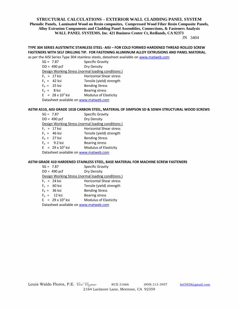
TYPE 304 SERIES AUSTENITIC STAINLESS STEEL- AISI – FOR COLD FORMED HARDENED THREAD ROLLED SCREW FASTENERS WITH SELF DRILLING TIP. FOR FASTENING ALUMINUM ALLOY EXTRUSIONS AND PANEL MATERIAL. as per the AISI Series Type 304 stainless steels, datasheet available on www.matweb.com
SG = 7.87 Specific Gravity DD = 490 pcf Dry Density
Design Working Stress (normal loading conditions ) Fv = 17 ksi Horizontal Shear stress Fy = 42 ksi Tensile (yield) strength Fb = 25 ksi Bending Stress
Fp = 8 ksi Bearing stress E = 28 x 103 ksi Modulus of Elasticity
Datasheet available on www.matweb.com
ASTM A510, AISI GRADE 1018 CARBON STEEL, MATERIAL OF SIMPSON SD & SDWH STRUCTURAL WOOD SCREWS SG = 7.87 Specific Gravity
DD = 490 pcf Dry Density Design Working Stress (normal loading conditions )
Fv = 17 ksi Horizontal Shear stress Fy = 46 ksi Tensile (yield) strength Fb = 27 ksi Bending Stress
Fp = 9.2 ksi Bearing stress E = 29 x 103 ksi Modulus of Elasticity
Datasheet available on www.matweb.com
ASTM GRADE 410 HARDENED STAINLESS STEEL, BASE MATERIAL FOR MACHINE SCREW FASTENERS SG = 7.87 Specific Gravity
DD = 490 pcf Dry Density Design Working Stress (normal loading conditions )
Fv = 24 ksi Horizontal Shear stress Fy = 60 ksi Tensile (yield) strength Fb = 36 ksi Bending Stress
Fp = 12 ksi Bearing stress E = 29 x 103 ksi Modulus of Elasticity
Datasheet available on www.matweb.com
STRUCTURAL CALCULATIONS – EXTERIOR WALL CLADDING PANEL SYSTEM Phenolic Panels, Laminated Wood on Resin composites, Compressed Wood Fiber Resin Composite Panels,
Alloy Extrusion Components and Cladding Panel Assemblies, Connections, & Fasteners Analysis
WALL PANEL SYSTEMS, Inc. 421 Business Center Ct, Redlands, CA 92373
JN 3404
Louis Waldo Flores, P.E. Civil Engineer RCE 31666 (909) 213-3957 [email protected]
2164 Larimore Lane, Mentone, CA 92359
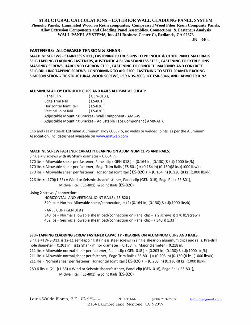
FASTENERS: ALLOWABLE TENSION & SHEAR : MACHINE SCREWS - STAINLESS STEEL, FASTENING EXTRUSIONS TO PHENOLIC & OTHER PANEL MATERIALS SELF-TAPPING CLADDING FASTENERS, AUSTENITIC AISI 304 STAINLESS STEEL, FASTENING TO EXTRUSIONS MASONRY SCREWS, HARDENED CARBON STEEL, FASTENING TO CONCRETE MASONRY AND CONCRETE SELF-DRILLING TAPPING SCREWS, CONFORMING TO AISI S200, FASTENING TO STEEL FRAMED BACKING SIMPSON STRONG TIE STRUCTURAL WOOD SCREWS, PER NDS-2005, ICC ESR-3046, AND IAPMO ER 0192 ALUMINUM ALLOY EXTRUDED CLIPS AND RAILS ALLOWABLE SHEAR:
Panel Clip ( GEN-018 ), Edge Trim Rail ( ES-801 ), Horizontal Joint Rail ( ES-820 ), Vertical Joint Rail ( ES-820 ). Adjustable Mounting Bracket - Wall Component ( AMB-W ). Adjustable Mounting Bracket – Adjustable Face Component ( AMB-AF ).
Clip and rail material: Extruded Aluminum alloy 6063-T5, no welds or welded joints, as per the Aluminum Association, Inc, datasheet available on www.matweb.com MACHINE SCREW FASTENER CAPACITY BEARING ON ALUMINUM CLIPS AND RAILS. Single # 8 screws with #8 Shank diameter = 0.064 in.
170 lbs = Allowable shear per fastener, Panel clip ( GEN-018 ) = (0.164 in) (0.130)(8 ksi)(1000 lbs/k) 170 lbs = Allowable shear per fastener, Edge Trim Rails ( ES-801 ) = (0.164 in) (0.130)(8 ksi)(1000 lbs/k)
170 lbs = Allowable shear per fastener, Horizontal Joint Rail ( ES-820 ) = (0.164 in) (0.130)(8 ksi)(1000 lbs/k).
226 lbs = (170)(1.33) = Wind or Seismic shear/fastener, Panel clip (GEN-018), Edge Rail ( ES-801),
Midwall Rail ( ES-801), & Joint Rails (ES-820)
Using 2 screws / connection: HORIZONTAL AND VERTICAL JOINT RAILS ( ES-820 ) 340 lbs = Normal Allowable shear/connection, = (2) (0.164 in) (0.130)(8 ksi)(1000 lbs/k)
PANEL CLIP ( GEN 018 ) 340 lbs = Normal allowable shear load/connection on Panel clip = ( 2 screws )( 170 lb/screw ) 452 lbs = Seismic allowable shear load/connection on Panel clip = ( 340 )( 1.33 )
SELF-TAPPING CLADDING SCREW FASTENER CAPACITY - BEARING ON ALUMINUM CLIPS AND RAILS. Single #TW-S-D13, # 12-11 self-tapping stainless steel screws in single shear on aluminum clips and rails. Pre-drill hole diameter = 0.203 in. #12 Shank minor diameter = 0.158 in. Major diameter = 0.218 in.
211 lbs = Allowable normal shear per fastener, Panel clip ( GEN-018 ) = (0.203 in) (0.130)(8 ksi)(1000 lbs/k) 211 lbs = Allowable normal shear per fastener, Edge Trim Rails ( ES-801 ) = (0.203 in) (0.130)(8 ksi)(1000 lbs/k)
211 lbs = Normal shear per fastener, Horizontal Joint Rail ( ES-820 ) = (0.203 in) (0.130)(8 ksi)(1000 lbs/k).
280.6 lbs = (211)(1.33) = Wind or Seismic shear/fastener, Panel clip (GEN-018), Edge Rail ( ES-801),
Midwall Rail ( ES-801), & Joint Rails (ES-820)
STRUCTURAL CALCULATIONS – EXTERIOR WALL CLADDING PANEL SYSTEM Phenolic Panels, Laminated Wood on Resin composites, Compressed Wood Fiber Resin Composite Panels,
Alloy Extrusion Components and Cladding Panel Assemblies, Connections, & Fasteners Analysis
WALL PANEL SYSTEMS, Inc. 421 Business Center Ct, Redlands, CA 92373
JN 3404
Louis Waldo Flores, P.E. Civil Engineer RCE 31666 (909) 213-3957 [email protected]
2164 Larimore Lane, Mentone, CA 92359
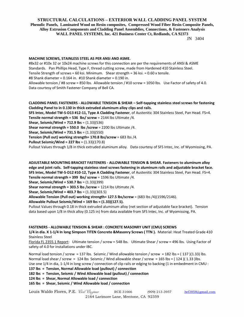
MACHINE SCREWS, STAINLESS STEEL AS PER ANSI AND ASME. #8x32 or #10x 32 or 10x24 machine screws for this connection are per the requirements of ANSI & ASME Standards. Pan Phillips Head, Type F, thread cutting screw, made from Hardened 410 Stainless Steel. Tensile Strength of screws = 60 ksi. Minimum. Shear strength = 36 ksi. = 0.60 x tensile. #8 Shank diameter = 0.164 in. #10 Shank diameter = 0.190 in. Allowable tension / #8 screw = 850 lbs. Allowable tension / #10 screw = 1050 lbs. Use Factor of safety of 4.0. Data courtesy of Smith Fastener Company of Bell CA.
CLADDING PANEL FASTENERS - ALLOWABLE TENSION & SHEAR – Self-tapping stainless steel screws for fastening Cladding Panel to in 0.130 in thick extruded aluminum alloy clips and rails. SFS Intec, Model TW-S-D13 #12-11, Type A Cladding Fastener, of Austenitic 304 Stainless Steel, Pan Head. FS=4. Tensile normal strength = 536 lbs/ screw = 2144 lbs Ultimate /4. Shear, Seismic/Wind = 712.9 lbs = (1.33)(536) Shear normal strength = 550.0 lbs /screw = 2200 lbs Ultimate /4. Shear, Seismic/Wind = 731.5 lbs = (1.33)(550) Tension (Pull out) working strength= 170.8 lbs/screw = 683 lbs /4. Pullout Seismic/Wind = 227 lbs = (1.33)(170.8) Pullout Values through 1/8 in thick extruded aluminum alloy. Data courtesy of SFS Intec, Inc. of Wyomissing, PA.
ADJUSTABLE MOUNTING BRACKET FASTENERS - ALLOWABLE TENSION & SHEAR. Fasteners to aluminum alloy edge and joint rails. Self-tapping stainless steel screws fastening in aluminum rails and adjustable bracket face. SFS Intec, Model TW-S-D12 #10-12, Type A Cladding Fastener, of Austenitic 304 Stainless Steel, Pan Head. FS=4. Tensile normal strength = 399 lbs/ screw = 1596 lbs Ultimate /4. Shear, Seismic/Wind = 530.7 lbs = (1.33)(399) Shear normal strength = 303.5 lbs /screw = 1214 lbs Ultimate /4. Shear, Seismic/Wind = 403.7 lbs = (1.33)(303.5) Allowable Tension (Pull out) working strength= 127.5 lbs/screw = (683 lbs /4)(1596/2146). Allowable Pullout Seismic/Wind = 169 lbs = (1.33)(127.5). Pullout Values through 0.18 in thick extruded aluminum alloy (net section of adjustable face bracket). Tension data based upon 1/8 in thick alloy (0.125 in) from data available from SFS Intec, Inc. of Wyomissing, PA.
FASTENERS - ALLOWABLE TENSION & SHEAR : CONCRETE MASONRY UNIT (CMU) SCREWS 1/4 in dia. X 1-1/4 In long Simpson TITEN Concrete &Masonry Screws ( TTN ). Material: Heat Treated Grade 410 Stainless Steel Florida FL 2355.1 Report: Ultimate tension / screw = 548 lbs. Ultimate Shear / screw = 496 lbs. Using Factor of safety of 4.0 for installations under IBC.
Normal load tension / screw = 137 lbs. Seismic / Wind allowable tension / screw = 182 lbs = ( 137 )(1.33) lbs. Normal load shear / screw = 124 lbs Seismic / Wind allowable shear / screw = 165 lbs = ( 124 )( 1.33 )lbs. Use one 1/4 in dia, 1-1/4 in long screw / connection of clip rails or edging to backing (1 in embedment in CMU : 137 lbs = Tension, Normal Allowable load (pullout) / connection 182 lbs = Tension, Seismic / Wind Allowable load (pullout) / connection 124 lbs = Shear, Normal Allowable load / connection 165 lbs = Shear, Seismic / Wind Allowable load / connection
STRUCTURAL CALCULATIONS – EXTERIOR WALL CLADDING PANEL SYSTEM Phenolic Panels, Laminated Wood on Resin composites, Compressed Wood Fiber Resin Composite Panels,
Alloy Extrusion Components and Cladding Panel Assemblies, Connections, & Fasteners Analysis
WALL PANEL SYSTEMS, Inc. 421 Business Center Ct, Redlands, CA 92373
JN 3404
Louis Waldo Flores, P.E. Civil Engineer RCE 31666 (909) 213-3957 [email protected]
2164 Larimore Lane, Mentone, CA 92359
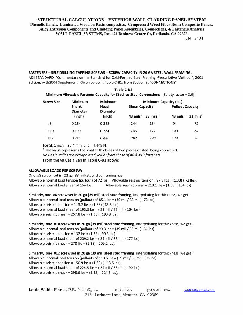
FASTENERS – SELF DRILLING TAPPING SCREWS – SCREW CAPACITY IN 20 GA STEEL WALL FRAMING. AISI STANDARD “Commentary on the Standard for Cold-Formed Steel Framing -Prescriptive Method ”, 2001 Edition, with2004 Supplement. Given below is Table C-B1, from Section B, “CONNECTIONS”
Table C-B1 Minimum Allowable Fastener Capacity for Steel-to-Steel Connections [Safety factor = 3.0]
Screw Size Minimum Minimum Minimum Capacity (lbs) Shank Head Shear Capacity Pullout Capacity
Diameter Diameter (inch) (inch) 43 mils1 33 mils1 43 mils1 33 mils1
#8 0.164 0.322 244 164 94 72
#10 0.190 0.384 263 177 109 84
#12 0.215 0.446 282 190 124 96
For SI: 1 inch = 25.4 mm, 1 lb = 4.448 N. 1 The value represents the smaller thickness of two pieces of steel being connected. Values in italics are extrapolated values from those of #8 & #10 fasteners.
From the values given in Table C-B1 above: ALLOWABLE LOADS PER SCREW: One #8 screw, set in 22 ga (33 mil) steel stud framing has: Allowable normal load tension (pullout) of 72 lbs. Allowable seismic tension =97.8 lbs = (1.33) ( 72 lbs). Allowable normal load shear of 164 lbs. Allowable seismic shear = 218.1 lbs = (1.33) ( 164 lbs) Similarly, one #8 screw set in 20 ga (39 mil) steel stud framing, interpolating for thickness, we get: Allowable normal load tension (pullout) of 85.1 lbs = (39 mil / 33 mil ) (72 lbs). Allowable seismic tension = 113.2 lbs = (1.33) ( 85.3 lbs). Allowable normal load shear of 193.8 lbs = ( 39 mil / 33 mil )(164 lbs), Allowable seismic shear = 257.8 lbs = (1.33) ( 193.8 lbs), Similarly, one #10 screw set in 20 ga (39 mil) steel stud framing, interpolating for thickness, we get: Allowable normal load tension (pullout) of 99.3 lbs = (39 mil / 33 mil ) (84 lbs). Allowable seismic tension = 132 lbs = (1.33) ( 99.3 lbs). Allowable normal load shear of 209.2 lbs = ( 39 mil / 33 mil )(177 lbs), Allowable seismic shear = 278 lbs = (1.33) ( 209.2 lbs), Similarly, one #12 screw set in 20 ga (39 mil) steel stud framing, interpolating for thickness, we get: Allowable normal load tension (pullout) of 113.5 lbs = (39 mil / 33 mil ) (96 lbs). Allowable seismic tension = 150.9 lbs = (1.33) ( 113.5 lbs). Allowable normal load shear of 224.5 lbs = ( 39 mil / 33 mil )(190 lbs), Allowable seismic shear = 298.6 lbs = (1.33) ( 224.5 lbs),
STRUCTURAL CALCULATIONS – EXTERIOR WALL CLADDING PANEL SYSTEM Phenolic Panels, Laminated Wood on Resin composites, Compressed Wood Fiber Resin Composite Panels,
Alloy Extrusion Components and Cladding Panel Assemblies, Connections, & Fasteners Analysis
WALL PANEL SYSTEMS, Inc. 421 Business Center Ct, Redlands, CA 92373
JN 3404
Louis Waldo Flores, P.E. Civil Engineer RCE 31666 (909) 213-3957 [email protected]
2164 Larimore Lane, Mentone, CA 92359
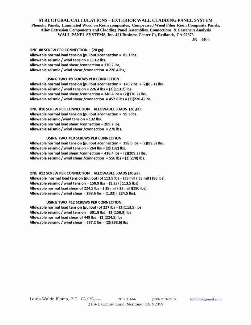
ONE #8 SCREW PER CONNECTION : (20 ga): Allowable normal load tension (pullout)/connection = 85.1 lbs. Allowable seismic / wind tension = 113.2 lbs. Allowable normal load shear /connection = 170.2 lbs, Allowable seismic / wind shear /connection = 226.4 lbs,
USING TWO #8 SCREWS PER CONNECTION : Allowable normal load tension (pullout)/connection = 170.2lbs = (2)(85.1) lbs. Allowable seismic / wind tension = 226.4 lbs = (2)(113.2) lbs. Allowable normal load shear /connection = 340.4 lbs = (2)(170.2) lbs, Allowable seismic / wind shear /connection = 452.8 lbs = (2)(226.4) lbs, ONE #10 SCREW PER CONNECTION : ALLOWABLE LOADS (20 ga): Allowable normal load tension (pullout)/connection = 99.3 lbs. Allowable seismic /wind tension = 132 lbs. Allowable normal load shear /connection = 209.2 lbs, Allowable seismic / wind shear /connection = 278 lbs.
USING TWO #10 SCREWS PER CONNECTION : Allowable normal load tension (pullout)/connection = 198.6 lbs = (2)(99.3) lbs. Allowable seismic / wind tension = 264 lbs = (2)(132) lbs. Allowable normal load shear /connection = 418.4 lbs = (2)(209.2) lbs, Allowable seismic / wind shear /connection = 556 lbs = (2)(278) lbs. ONE #12 SCREW PER CONNECTION : ALLOWABLE LOADS (20 ga): Allowable normal load tension (pullout) of 113.5 lbs = (39 mil / 33 mil ) (96 lbs). Allowable seismic / wind tension = 150.9 lbs = (1.33) ( 113.5 lbs). Allowable normal load shear of 224.5 lbs = ( 39 mil / 33 mil )(190 lbs), Allowable seismic / wind shear = 298.6 lbs = (1.33) ( 224.5 lbs).
USING TWO #12 SCREWS PER CONNECTION : Allowable normal load tension (pullout) of 227 lbs = (2)(113.5) lbs. Allowable seismic / wind tension = 301.8 lbs = (2)(150.9) lbs Allowable normal load shear of 449 lbs = (2)(224.5) lbs Allowable seismic / wind shear = 597.2 lbs = (2)(298.6) lbs
STRUCTURAL CALCULATIONS – EXTERIOR WALL CLADDING PANEL SYSTEM Phenolic Panels, Laminated Wood on Resin composites, Compressed Wood Fiber Resin Composite Panels,
Alloy Extrusion Components and Cladding Panel Assemblies, Connections, & Fasteners Analysis
WALL PANEL SYSTEMS, Inc. 421 Business Center Ct, Redlands, CA 92373
JN 3404
Louis Waldo Flores, P.E. Civil Engineer RCE 31666 (909) 213-3957 [email protected]
2164 Larimore Lane, Mentone, CA 92359
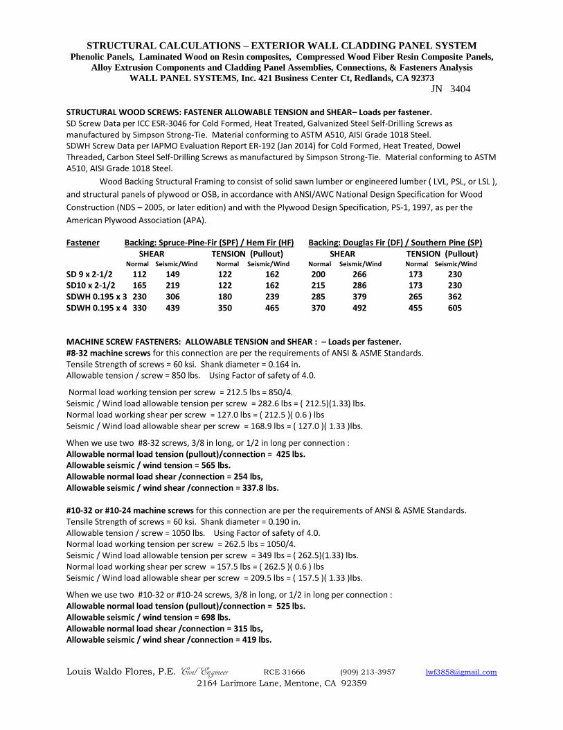
STRUCTURAL WOOD SCREWS: FASTENER ALLOWABLE TENSION and SHEAR– Loads per fastener. SD Screw Data per ICC ESR-3046 for Cold Formed, Heat Treated, Galvanized Steel Self-Drilling Screws as manufactured by Simpson Strong-Tie. Material conforming to ASTM A510, AISI Grade 1018 Steel. SDWH Screw Data per IAPMO Evaluation Report ER-192 (Jan 2014) for Cold Formed, Heat Treated, Dowel Threaded, Carbon Steel Self-Drilling Screws as manufactured by Simpson Strong-Tie. Material conforming to ASTM A510, AISI Grade 1018 Steel.
Wood Backing Structural Framing to consist of solid sawn lumber or engineered lumber ( LVL, PSL, or LSL ),
and structural panels of plywood or OSB, in accordance with ANSI/AWC National Design Specification for Wood
Construction (NDS – 2005, or later edition) and with the Plywood Design Specification, PS-1, 1997, as per the
American Plywood Association (APA). Fastener Backing: Spruce-Pine-Fir (SPF) / Hem Fir (HF) Backing: Douglas Fir (DF) / Southern Pine (SP)
SHEAR TENSION (Pullout) SHEAR TENSION (Pullout) Normal Seismic/Wind Normal Seismic/Wind Normal Seismic/Wind Normal Seismic/Wind
SD 9 x 2-1/2 112 149 122 162 200 266 173 230 SD10 x 2-1/2 165 219 122 162 215 286 173 230 SDWH 0.195 x 3 230 306 180 239 285 379 265 362 SDWH 0.195 x 4 330 439 350 465 370 492 455 605 MACHINE SCREW FASTENERS: ALLOWABLE TENSION and SHEAR : – Loads per fastener. #8-32 machine screws for this connection are per the requirements of ANSI & ASME Standards. Tensile Strength of screws = 60 ksi. Shank diameter = 0.164 in. Allowable tension / screw = 850 lbs. Using Factor of safety of 4.0.
Normal load working tension per screw = 212.5 lbs = 850/4. Seismic / Wind load allowable tension per screw = 282.6 lbs = ( 212.5)(1.33) lbs. Normal load working shear per screw = 127.0 lbs = ( 212.5 )( 0.6 ) lbs Seismic / Wind load allowable shear per screw = 168.9 lbs = ( 127.0 )( 1.33 )lbs.
When we use two #8-32 screws, 3/8 in long, or 1/2 in long per connection : Allowable normal load tension (pullout)/connection = 425 lbs. Allowable seismic / wind tension = 565 lbs. Allowable normal load shear /connection = 254 lbs, Allowable seismic / wind shear /connection = 337.8 lbs. #10-32 or #10-24 machine screws for this connection are per the requirements of ANSI & ASME Standards. Tensile Strength of screws = 60 ksi. Shank diameter = 0.190 in. Allowable tension / screw = 1050 lbs. Using Factor of safety of 4.0. Normal load working tension per screw = 262.5 lbs = 1050/4. Seismic / Wind load allowable tension per screw = 349 lbs = ( 262.5)(1.33) lbs. Normal load working shear per screw = 157.5 lbs = ( 262.5 )( 0.6 ) lbs Seismic / Wind load allowable shear per screw = 209.5 lbs = ( 157.5 )( 1.33 )lbs.
When we use two #10-32 or #10-24 screws, 3/8 in long, or 1/2 in long per connection : Allowable normal load tension (pullout)/connection = 525 lbs. Allowable seismic / wind tension = 698 lbs. Allowable normal load shear /connection = 315 lbs, Allowable seismic / wind shear /connection = 419 lbs.
STRUCTURAL CALCULATIONS – EXTERIOR WALL CLADDING PANEL SYSTEM Phenolic Panels, Laminated Wood on Resin composites, Compressed Wood Fiber Resin Composite Panels,
Alloy Extrusion Components and Cladding Panel Assemblies, Connections, & Fasteners Analysis
WALL PANEL SYSTEMS, Inc. 421 Business Center Ct, Redlands, CA 92373
JN 3404
Louis Waldo Flores, P.E. Civil Engineer RCE 31666 (909) 213-3957 [email protected]
2164 Larimore Lane, Mentone, CA 92359
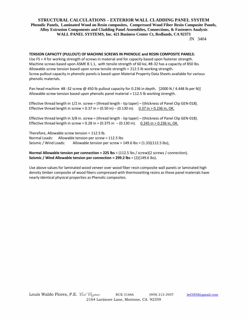
TENSION CAPACITY (PULLOUT) OF MACHINE SCREWS IN PHENOLIC and RESIN COMPOSITE PANELS: Use FS = 4 for working strength of screws in material and for capacity based upon fastener strength. Machine screws based upon ASME B 1.1, with tensile strength of 60 ksi, #8-32 has a capacity of 850 lbs. Allowable screw tension based upon screw tensile strength = 212.5 lb working strength. Screw pullout capacity in phenolic panels is based upon Material Property Data Sheets available for various phenolic materials. Pan head machine #8 -32 screw @ 450 lb pullout capacity for 0.236 in depth. [2000 N / 4.448 lb per N)] Allowable screw tension based upon phenolic panel material = 112.5 lb working strength. Effective thread length in 1/2 in. screw = (thread length - tip taper) – (thickness of Panel Clip GEN-018). Effective thread length in screw = 0.37 in = (0.50 in) – (0.130 in). 0.37 in > 0.236 in, OK. Effective thread length in 3/8 in. screw = (thread length - tip taper) – (thickness of Panel Clip GEN-018). Effective thread length in screw = 0.28 in = (0.375 in – (0.130 in). 0.245 in > 0.236 in, OK. Therefore, Allowable screw tension = 112.5 lb. Normal Loads: Allowable tension per screw = 112.5 lbs Seismic / Wind Loads: Allowable tension per screw = 149.6 lbs = (1.33)(112.5 lbs), Normal Allowable tension per connection = 225 lbs = (112.5 lbs / screw)(2 screws / connection). Seismic / Wind Allowable tension per connection = 299.2 lbs = (2)(149.6 lbs). Use above values for laminated wood veneer over wood fiber resin composite wall panels or laminated high density timber composite of wood fibers compressed with thermosetting resins as these panel materials have nearly identical physical properties as Phenolic composites.
STRUCTURAL CALCULATIONS – EXTERIOR WALL CLADDING PANEL SYSTEM Phenolic Panels, Laminated Wood on Resin composites, Compressed Wood Fiber Resin Composite Panels,
Alloy Extrusion Components and Cladding Panel Assemblies, Connections, & Fasteners Analysis
WALL PANEL SYSTEMS, Inc. 421 Business Center Ct, Redlands, CA 92373
JN 3404
Louis Waldo Flores, P.E. Civil Engineer RCE 31666 (909) 213-3957 [email protected]
2164 Larimore Lane, Mentone, CA 92359
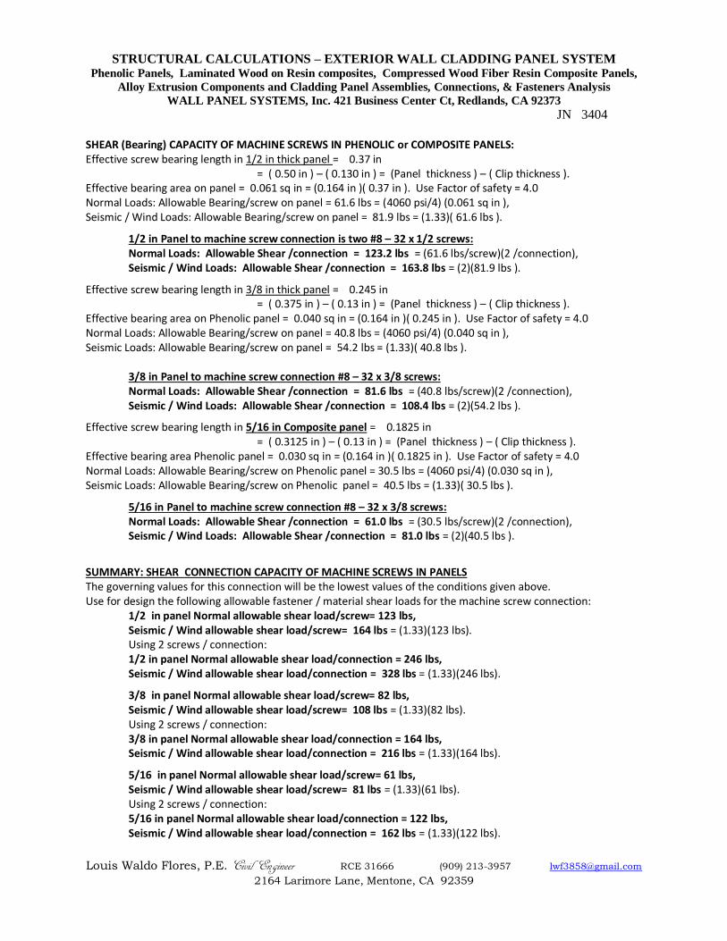
SHEAR (Bearing) CAPACITY OF MACHINE SCREWS IN PHENOLIC or COMPOSITE PANELS: Effective screw bearing length in 1/2 in thick panel = 0.37 in
= ( 0.50 in ) – ( 0.130 in ) = (Panel thickness ) – ( Clip thickness ). Effective bearing area on panel = 0.061 sq in = (0.164 in )( 0.37 in ). Use Factor of safety = 4.0 Normal Loads: Allowable Bearing/screw on panel = 61.6 lbs = (4060 psi/4) (0.061 sq in ), Seismic / Wind Loads: Allowable Bearing/screw on panel = 81.9 lbs = (1.33)( 61.6 lbs ).
1/2 in Panel to machine screw connection is two #8 – 32 x 1/2 screws: Normal Loads: Allowable Shear /connection = 123.2 lbs = (61.6 lbs/screw)(2 /connection), Seismic / Wind Loads: Allowable Shear /connection = 163.8 lbs = (2)(81.9 lbs ).
Effective screw bearing length in 3/8 in thick panel = 0.245 in = ( 0.375 in ) – ( 0.13 in ) = (Panel thickness ) – ( Clip thickness ).
Effective bearing area on Phenolic panel = 0.040 sq in = (0.164 in )( 0.245 in ). Use Factor of safety = 4.0 Normal Loads: Allowable Bearing/screw on panel = 40.8 lbs = (4060 psi/4) (0.040 sq in ), Seismic Loads: Allowable Bearing/screw on panel = 54.2 lbs = (1.33)( 40.8 lbs ).
3/8 in Panel to machine screw connection #8 – 32 x 3/8 screws: Normal Loads: Allowable Shear /connection = 81.6 lbs = (40.8 lbs/screw)(2 /connection), Seismic / Wind Loads: Allowable Shear /connection = 108.4 lbs = (2)(54.2 lbs ).
Effective screw bearing length in 5/16 in Composite panel = 0.1825 in = ( 0.3125 in ) – ( 0.13 in ) = (Panel thickness ) – ( Clip thickness ).
Effective bearing area Phenolic panel = 0.030 sq in = (0.164 in )( 0.1825 in ). Use Factor of safety = 4.0 Normal Loads: Allowable Bearing/screw on Phenolic panel = 30.5 lbs = (4060 psi/4) (0.030 sq in ), Seismic Loads: Allowable Bearing/screw on Phenolic panel = 40.5 lbs = (1.33)( 30.5 lbs ).
5/16 in Panel to machine screw connection #8 – 32 x 3/8 screws: Normal Loads: Allowable Shear /connection = 61.0 lbs = (30.5 lbs/screw)(2 /connection), Seismic / Wind Loads: Allowable Shear /connection = 81.0 lbs = (2)(40.5 lbs ).
SUMMARY: SHEAR CONNECTION CAPACITY OF MACHINE SCREWS IN PANELS The governing values for this connection will be the lowest values of the conditions given above. Use for design the following allowable fastener / material shear loads for the machine screw connection:
1/2 in panel Normal allowable shear load/screw= 123 lbs, Seismic / Wind allowable shear load/screw= 164 lbs = (1.33)(123 lbs). Using 2 screws / connection: 1/2 in panel Normal allowable shear load/connection = 246 lbs, Seismic / Wind allowable shear load/connection = 328 lbs = (1.33)(246 lbs).
3/8 in panel Normal allowable shear load/screw= 82 lbs, Seismic / Wind allowable shear load/screw= 108 lbs = (1.33)(82 lbs). Using 2 screws / connection: 3/8 in panel Normal allowable shear load/connection = 164 lbs, Seismic / Wind allowable shear load/connection = 216 lbs = (1.33)(164 lbs).
5/16 in panel Normal allowable shear load/screw= 61 lbs, Seismic / Wind allowable shear load/screw= 81 lbs = (1.33)(61 lbs). Using 2 screws / connection: 5/16 in panel Normal allowable shear load/connection = 122 lbs, Seismic / Wind allowable shear load/connection = 162 lbs = (1.33)(122 lbs).
STRUCTURAL CALCULATIONS – EXTERIOR WALL CLADDING PANEL SYSTEM Phenolic Panels, Laminated Wood on Resin composites, Compressed Wood Fiber Resin Composite Panels,
Alloy Extrusion Components and Cladding Panel Assemblies, Connections, & Fasteners Analysis
WALL PANEL SYSTEMS, Inc. 421 Business Center Ct, Redlands, CA 92373
JN 3404
Louis Waldo Flores, P.E. Civil Engineer RCE 31666 (909) 213-3957 [email protected]
2164 Larimore Lane, Mentone, CA 92359
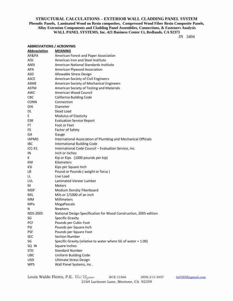
ABBREVIATIONS / ACRONYMS Abbreviation MEANING AF&PA American Forest and Paper Association AISI American Iron and Steel Institute ANSI American National Standards Institute APA American Plywood Association ASD Allowable Stress Design ASCE American Society of Civil Engineers ASME American Society of Mechanical Engineers ASTM American Society of Testing and Materials AWC American Wood Council CBC California Building Code CONN Connection DIA Diameter DL Dead Load E Modulus of Elasticity ESR Evaluation Service Report FT Foot or Feet FS Factor of Safety GA Gauge IAPMO International Association of Plumbing and Mechanical Officials IBC International Building Code ICC-ES International Code Council – Evaluation Service, Inc. IN Inch or Inches K Kip or Kips (1000 pounds per kip) KM Kilometers KSI Kips per Square Inch LB Pound or Pounds ( weight or force ) LL Live Load LVL Laminated Veneer Lumber M Meters MDF Medium Density Fiberboard MIL Mils or 1/1000 of an inch MM Millimeters MPa MegaPascals N Newtons NDS-2005 National Design Specification for Wood Construction, 2005 edition SG Specific Gravity PCF Pounds per Cubic Foot PSI Pounds per Square Inch PSF Pounds per Square Foot SEC Section Number SG Specific Gravity (relative to water where SG of water = 1.00) SQ IN Square Inches STD Standard Number UBC Uniform Building Code USD Ultimate Stress Design WPS Wall Panel Systems, Inc .
STRUCTURAL CALCULATIONS – EXTERIOR WALL CLADDING PANEL SYSTEM Phenolic Panels, Laminated Wood on Resin composites, Compressed Wood Fiber Resin Composite Panels,
Alloy Extrusion Components and Cladding Panel Assemblies, Connections, & Fasteners Analysis
WALL PANEL SYSTEMS, Inc. 421 Business Center Ct, Redlands, CA 92373
JN 3404
Louis Waldo Flores, P.E. Civil Engineer RCE 31666 (909) 213-3957 [email protected]
2164 Larimore Lane, Mentone, CA 92359
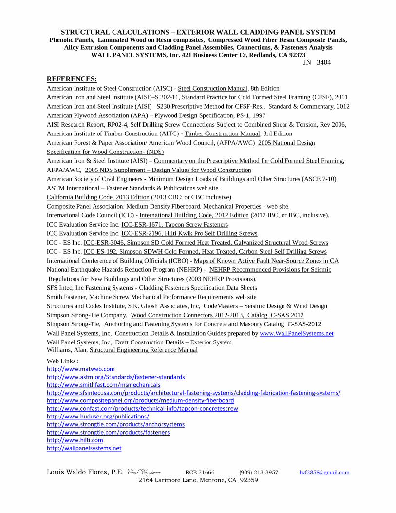
REFERENCES:
American Institute of Steel Construction (AISC) - Steel Construction Manual, 8th Edition
American Iron and Steel Institute (AISI)–S 202-11, Standard Practice for Cold Formed Steel Framing (CFSF), 2011
American Iron and Steel Institute (AISI)– S230 Prescriptive Method for CFSF-Res., Standard & Commentary, 2012
American Plywood Association (APA) – Plywood Design Specification, PS-1, 1997
AISI Research Report, RP02-4, Self Drilling Screw Connections Subject to Combined Shear & Tension, Rev 2006,
American Institute of Timber Construction (AITC) - Timber Construction Manual, 3rd Edition
American Forest & Paper Association/ American Wood Council, (AFPA/AWC) 2005 National Design
Specification for Wood Construction- (NDS)
American Iron & Steel Institute (AISI) – Commentary on the Prescriptive Method for Cold Formed Steel Framing,
AFPA/AWC, 2005 NDS Supplement – Design Values for Wood Construction
American Society of Civil Engineers - Minimum Design Loads of Buildings and Other Structures (ASCE 7-10)
ASTM International – Fastener Standards & Publications web site.
California Building Code, 2013 Edition (2013 CBC; or CBC inclusive).
Composite Panel Association, Medium Density Fiberboard, Mechanical Properties - web site.
International Code Council (ICC) - International Building Code, 2012 Edition (2012 IBC, or IBC, inclusive).
ICC Evaluation Service Inc. ICC-ESR-1671, Tapcon Screw Fasteners
ICC Evaluation Service Inc. ICC-ESR-2196, Hilti Kwik Pro Self Drilling Screws
ICC - ES Inc. ICC-ESR-3046, Simpson SD Cold Formed Heat Treated, Galvanized Structural Wood Screws
ICC - ES Inc. ICC-ES-192, Simpson SDWH Cold Formed, Heat Treated, Carbon Steel Self Drilling Screws
International Conference of Building Officials (ICBO) - Maps of Known Active Fault Near-Source Zones in CA
National Earthquake Hazards Reduction Program (NEHRP) - NEHRP Recommended Provisions for Seismic
Regulations for New Buildings and Other Structures (2003 NEHRP Provisions).
SFS Intec, Inc Fastening Systems - Cladding Fasteners Specification Data Sheets
Smith Fastener, Machine Screw Mechanical Performance Requirements web site
Structures and Codes Institute, S.K. Ghosh Associates, Inc, CodeMasters – Seismic Design & Wind Design
Simpson Strong-Tie Company, Wood Construction Connectors 2012-2013, Catalog C-SAS 2012
Simpson Strong-Tie, Anchoring and Fastening Systems for Concrete and Masonry Catalog C-SAS-2012
Wall Panel Systems, Inc, Construction Details & Installation Guides prepared by www.WallPanelSystems.net
Wall Panel Systems, Inc, Draft Construction Details – Exterior System
Williams, Alan, Structural Engineering Reference Manual
Web Links :
http://www.matweb.com http://www.astm.org/Standards/fastener-standards http://www.smithfast.com/msmechanicals http://www.sfsintecusa.com/products/architectural-fastening-systems/cladding-fabrication-fastening-systems/ http://www.compositepanel.org/products/medium-density-fiberboard http://www.confast.com/products/technical-info/tapcon-concretescrew http://www.huduser.org/publications/ http://www.strongtie.com/products/anchorsystems http://www.strongtie.com/products/fasteners http://www.hilti.com http://wallpanelsystems.net