Embed Size (px)
Citation preview

1
Microstructure-‐Properties: I Materials Properties: Strength, Ductility
27-‐301 Profs. A. D. Rolle3,
M. De Graef
Microstructure Properties
Processing Performance
Last revised 27th Sept. 2015
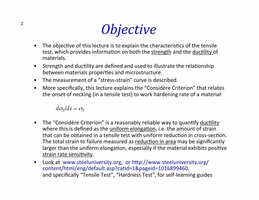
2 Objective • The objec>ve of this lecture is to explain the characteris>cs of the tensile
test, which provides informa>on on both the strength and the duc>lity of materials.
• Strength and duc>lity are defined and used to illustrate the rela>onship between materials proper>es and microstructure.
• The measurement of a “stress-‐strain” curve is described. • More specifically, this lecture explains the “Considère Criterion” that relates
the onset of necking (in a tensile test) to work hardening rate of a material:
dσT/dε = σT
• The “Considère Criterion” is a reasonably reliable way to quan>fy duc>lity where this is defined as the uniform elonga>on, i.e. the amount of strain that can be obtained in a tensile test with uniform reduc>on in cross-‐sec>on. The total strain to failure measured as reduc>on in area may be significantly larger than the uniform elonga>on, especially if the material exhibits posi>ve strain rate sensi>vity.
• Look at www.steeluniversity.org, or h3p://www.steeluniversity.org/content/html/eng/default.asp?ca>d=1&pageid=1016899460, and specifically “Tensile Test”, “Hardness Test”, for self-‐learning guides
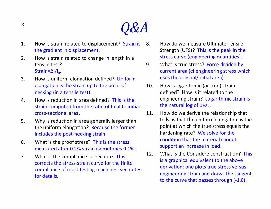
Q&A 1. How is strain related to displacement? Strain is
the gradient in displacement. 2. How is strain related to change in length in a
tensile test? Strain=∆l/l0.
3. How is uniform elonga>on defined? Uniform elonga>on is the strain up to the point of necking (in a tensile test).
4. How is reduc>on in area defined? This is the strain computed from the ra>o of final to ini>al cross-‐sec>onal area.
5. Why is reduc>on in area generally larger than the uniform elonga>on? Because the former includes the post-‐necking strain.
6. What is the proof stress? This is the stress measured aeer 0.2% strain (some>mes 0.1%).
7. What is the compliance correc>on? This corrects the stress-‐strain curve for the finite compliance of most tes>ng machines; see notes for details.
8. How do we measure Ul>mate Tensile Strength (UTS)? This is the peak in the stress curve (engineering quan>>es).
9. What is true stress? Force divided by current area (cf engineering stress which uses the original/ini>al area).
10. How is logarithmic (or true) strain defined? How is it related to the engineering strain? Logarithmic strain is the natural log of 1+εn.
11. How do we derive the rela>onship that tells us that the uniform elonga>on is the point at which the true stress equals the hardening rate? We solve for the condi>on that the material cannot support an increase in load.
12. What is the Considère construc>on? This is a graphical equivalent to the above deriva>on; one plots true stress versus engineering strain and draws the tangent to the curve that passes through (-‐1,0).
3
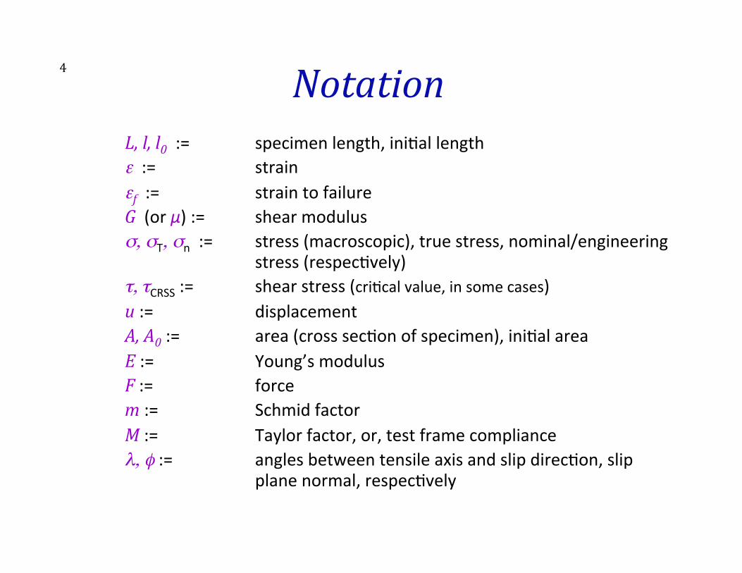
4 Notation L, l, l0 := specimen length, ini>al length ε := strain εf := strain to failure G (or µ) := shear modulus σ, σT, σn := stress (macroscopic), true stress, nominal/engineering
stress (respec>vely) τ, τCRSS := shear stress (cri>cal value, in some cases) u := displacement A, A0 := area (cross sec>on of specimen), ini>al area E := Young’s modulus F := force m := Schmid factor M := Taylor factor, or, test frame compliance λ, φ := angles between tensile axis and slip direc>on, slip
plane normal, respec>vely
5 Key Concepts • Stress, yield strength, typical values, extreme values • Strain, engineering versus logarithmic strain • Stress-‐strain curves • Compliance correc>on for stress-‐strain curves • Duc>lity, necking limit, rela>onship to hardening parameters,
Considère’s Criterion
6 Strength • Strength, or flow stress, is very basic to the value of a structural material. We
measure it in terms of force per unit (cross-‐sec>onal) area: σ = F/A • Strength means resistance to irreversible deforma>on or, if you prefer, the
upper limit of elas>c stress that is safe to apply to a material. • Strength is highly dependent on microstructure because it is propor>onal to
the difficulty of moving disloca>ons through (and between) the grains. • Typical values? Most useful structural metals have strengths in the range
100-‐1000 MPa; ultra-‐high strength steel wire can be produced with strengths greater than 5,000 MPa!
• Engineers are oeen taught strength as being related to (chemical) composi>on. Materials engineers study strengthening mechanisms and therefore understand how to control strength.
• Strength is typically measured in a tension test, but we will also examine this test when we discuss duc7lity.
• Mechanical engineers oeen are required to take a course in “Strength of Materials”, which discusses the mechanical proper>es of materials (oeen without reference to the microstructures, which explain the physical basis for the proper>es).
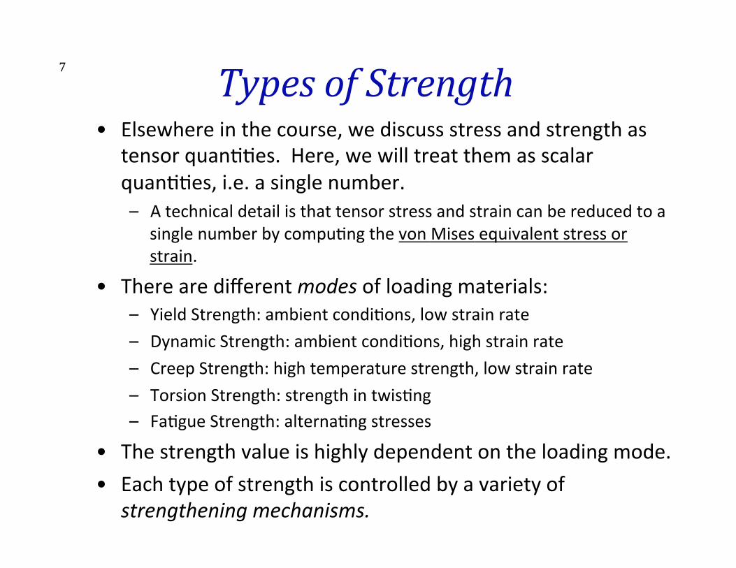
7 Types of Strength • Elsewhere in the course, we discuss stress and strength as
tensor quan>>es. Here, we will treat them as scalar quan>>es, i.e. a single number. – A technical detail is that tensor stress and strain can be reduced to a
single number by compu>ng the von Mises equivalent stress or strain.
• There are different modes of loading materials: – Yield Strength: ambient condi>ons, low strain rate – Dynamic Strength: ambient condi>ons, high strain rate – Creep Strength: high temperature strength, low strain rate – Torsion Strength: strength in twis>ng – Fa>gue Strength: alterna>ng stresses
• The strength value is highly dependent on the loading mode. • Each type of strength is controlled by a variety of
strengthening mechanisms.
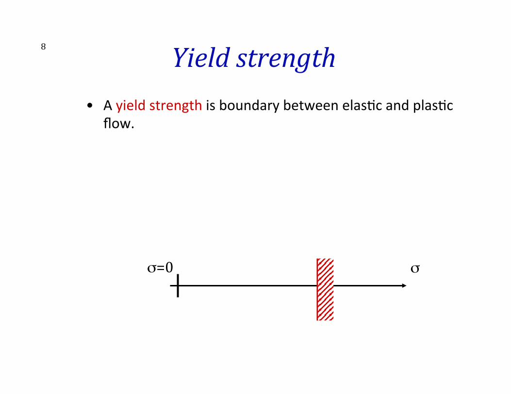
8 Yield strength • A yield strength is boundary between elas>c and plas>c
flow.
σ=0 σ elastic plastic Example: tensile stress
σ= σyield
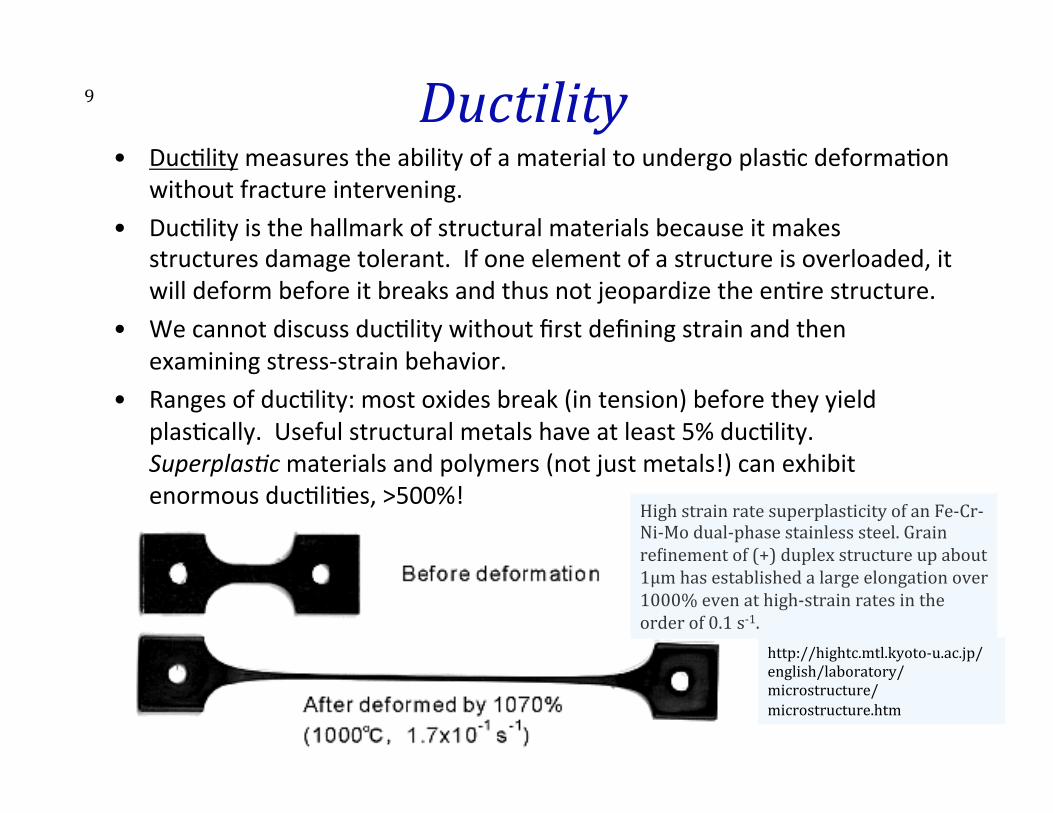
9 Ductility • Duc>lity measures the ability of a material to undergo plas>c deforma>on
without fracture intervening. • Duc>lity is the hallmark of structural materials because it makes
structures damage tolerant. If one element of a structure is overloaded, it will deform before it breaks and thus not jeopardize the en>re structure.
• We cannot discuss duc>lity without first defining strain and then examining stress-‐strain behavior.
• Ranges of duc>lity: most oxides break (in tension) before they yield plas>cally. Useful structural metals have at least 5% duc>lity. Superplas7c materials and polymers (not just metals!) can exhibit enormous duc>li>es, >500%!
http://hightc.mtl.kyoto-‐u.ac.jp/english/laboratory/microstructure/microstructure.htm
High strain rate superplasticity of an Fe-‐Cr-‐Ni-‐Mo dual-‐phase stainless steel. Grain reOinement of (+) duplex structure up about 1µm has established a large elongation over 1000% even at high-‐strain rates in the order of 0.1 s-‐1.
10 Strain • Strain measures the change in shape of a body. If you apply a force to a body, naturally there is a change in size. By normalizing the change in a given dimension by the original dimension, one arrives at a quan>ty that again can be used to characterize the proper>es of a material.
• strain = [change in length]/[original length]!!
ε = ∆L/L0 = (L-L0)/L0.!"
• Reminder: strain is, in general, a tensor because a body can change shape in all three direc>ons at once.
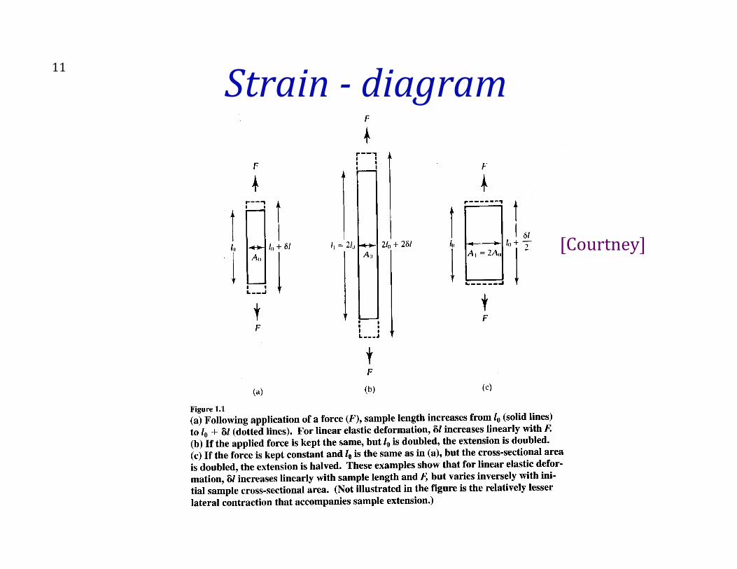
11 Strain -‐ diagram
[Courtney]
12 Strain -‐ notes • A be3er defini>on of strain is that of a gradient in
displacement of points in a body. Take a tensile strain as an example: if we fix one end of the body and apply a tensile force, then the fixed point does not move. The point at the other end of the body moves the most. The change in posi>on, i.e. the displacement, is then propor>onal to the distance away from the fixed point. The strain can then be defined as the gradient in displacement, u; ε = du/dx, where x is the posi>on along the body.
• In order to measure strain, one must choose points on a specimen, measure their spacing, perform the test, and then re-‐measure.
• Since strain is always a ra>o of lengths then it is dimensionless. Per-‐cent (%) is useful because many materials have duc>li>es less than 50%. Frac>onal strain is also used, however.
13 Stress-‐Strain: measurement • The measurement of the stress-‐strain characteris>cs of a
material, which we will perform in the second laboratory in 301, requires us to examine some prac>cal aspects.
• At ambient condi>ons and easily a3ained strain rates (room temperature, one atmosphere of air, strain rates between 10-‐5 and 100 per second), the most straighworward test is the tensile test. A bar of constant cross sec>on [area] is stretched at controlled displacement rate. The load required for the stretch is recorded.
• Essen>ally all materials exhibit a maximum strain, beyond which failure (fracture) occurs.
• Note that, although strength is a tensor quan>ty, one can only measure in one direc>on at once. In many cases, it is reasonable to assume isotropy.
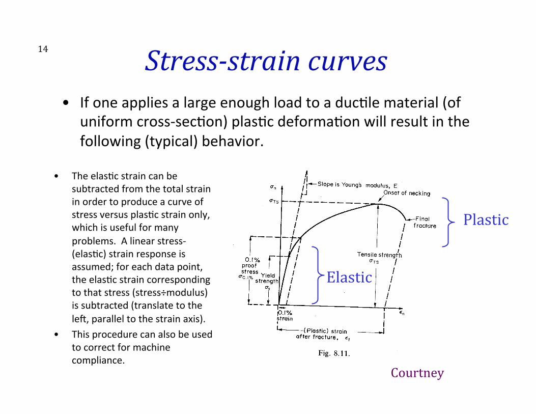
14 Stress-‐strain curves • If one applies a large enough load to a duc>le material (of
uniform cross-‐sec>on) plas>c deforma>on will result in the following (typical) behavior.
Elastic
Plastic
Courtney
• The elas>c strain can be subtracted from the total strain in order to produce a curve of stress versus plas>c strain only, which is useful for many problems. A linear stress-‐(elas>c) strain response is assumed; for each data point, the elas>c strain corresponding to that stress (stress÷modulus) is subtracted (translate to the lee, parallel to the strain axis).
• This procedure can also be used to correct for machine compliance.
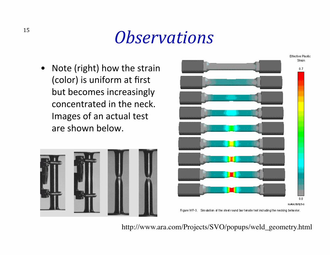
Observations 15
http://www.ara.com/Projects/SVO/popups/weld_geometry.html
• Note (right) how the strain (color) is uniform at first but becomes increasingly concentrated in the neck. Images of an actual test are shown below.
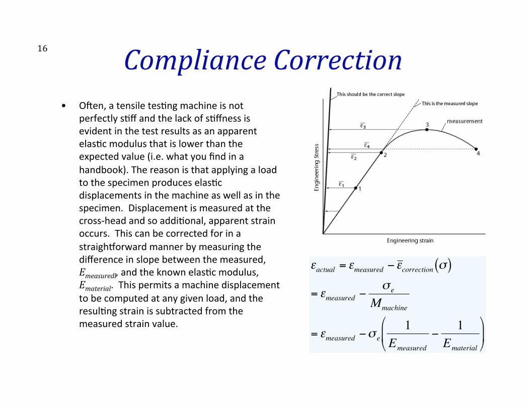
16 Compliance Correction • Oeen, a tensile tes>ng machine is not
perfectly s>ff and the lack of s>ffness is evident in the test results as an apparent elas>c modulus that is lower than the expected value (i.e. what you find in a handbook). The reason is that applying a load to the specimen produces elas>c displacements in the machine as well as in the specimen. Displacement is measured at the cross-‐head and so addi>onal, apparent strain occurs. This can be corrected for in a straighworward manner by measuring the difference in slope between the measured, Emeasuredl, and the known elas>c modulus, Ematerial. This permits a machine displacement to be computed at any given load, and the resul>ng strain is subtracted from the measured strain value.
€
εactual = εmeasured −ε correction σ( )
= εmeasured −σ e
Mmachine
= εmeasured −σ e1
Emeasured
−1
Ematerial
%
& '
(
) *
17 Stress-‐strain characteristics • The ini>al part of the curve represents the elas7c regime of the material. If the
load is released, the strain of the specimen will return to zero and no permanent deforma>on occurs. The slope of this part of the curve is called Young's modulus or Modulus of Elas>city.
• Further imposed strain results in a dras>c change in slope of the curve which signals the onset of permanent plas>c deforma>on. The yield strength is a measure of the stress required for permanent plas>c flow. The usual defini>on of this property is the offset yield strength determined by the stress corresponding to the intersec>on of the curve and a line parallel to the elas>c part but offset by a specific strain (usually 0.2%). Beyond this point, the material work hardens un>l the ul>mate tensile strength is a3ained. At this point, the incremental increases in stress due to decrease in cross-‐sec>onal area becomes greater than the increase in load carrying ability due to strain hardening. Star>ng at this point, all further strain is concentrated in the "necked" por>on of the specimen.
18 Ductility measures • The reduc>on of area at fracture and the elonga>on to fracture
are used as percent reduc>on of the original area and percentage increase of the original gage length. The percentage reduc>on of area at fracture is only slightly affected by the shape of the tensile test specimen. As long as the ra>o of the width to thickness does not exceed about 5:1, for a rectangular cross-‐sec>on, the percent reduc>on of area remains the same as for circular cross-‐sec>ons.
• Elonga>on to failure = εf = (LOinal-‐L0)/L0 x 100% • Reduc>on in Area = ( A0 – AOinal ) / A0 x 100% • The reduc>on of area is usually larger than the elonga>on to
fracture. This is the result of post-‐necking strain (to be discussed in more detail).
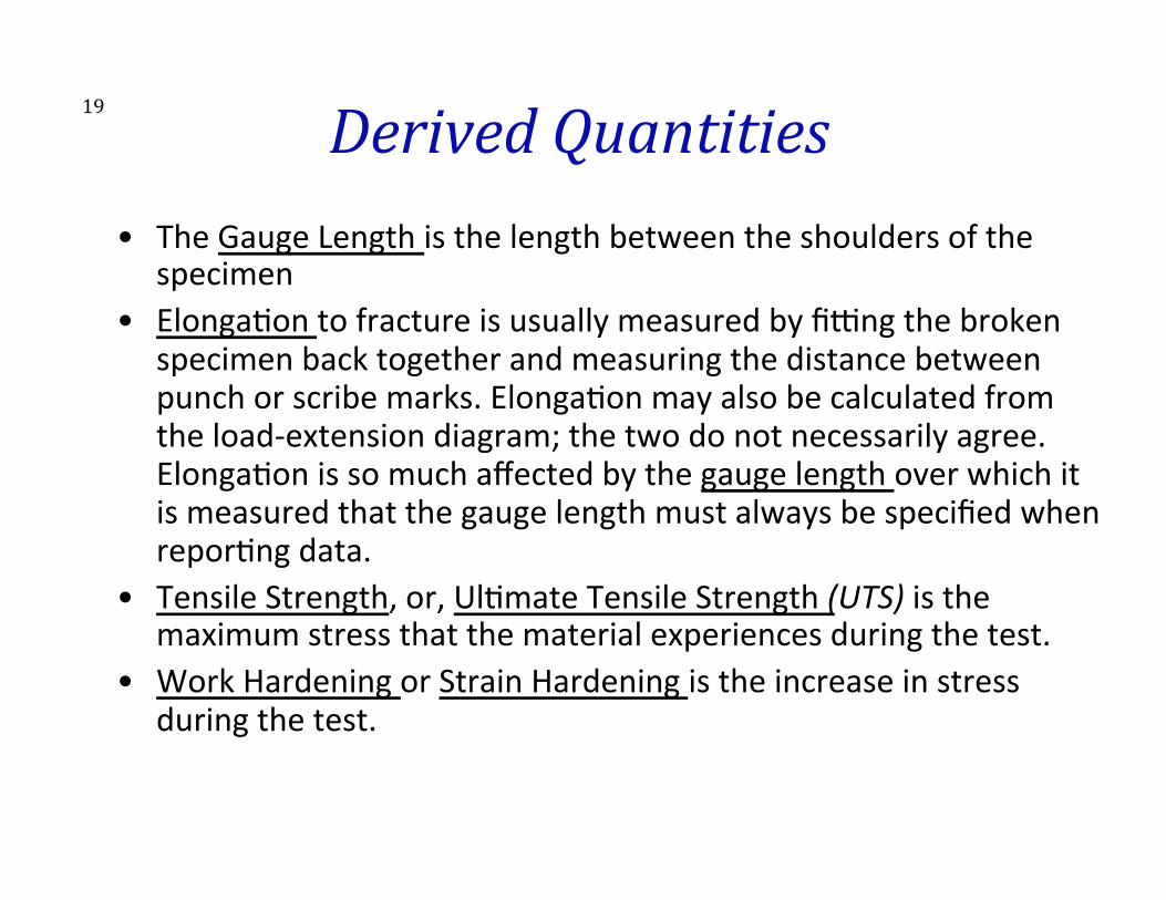
19 Derived Quantities • The Gauge Length is the length between the shoulders of the
specimen • Elonga>on to fracture is usually measured by fi|ng the broken
specimen back together and measuring the distance between punch or scribe marks. Elonga>on may also be calculated from the load-‐extension diagram; the two do not necessarily agree. Elonga>on is so much affected by the gauge length over which it is measured that the gauge length must always be specified when repor>ng data.
• Tensile Strength, or, Ul>mate Tensile Strength (UTS) is the maximum stress that the material experiences during the test.
• Work Hardening or Strain Hardening is the increase in stress during the test.
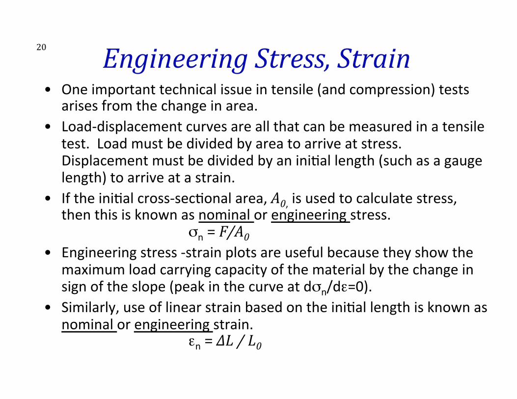
20 Engineering Stress, Strain • One important technical issue in tensile (and compression) tests
arises from the change in area. • Load-‐displacement curves are all that can be measured in a tensile
test. Load must be divided by area to arrive at stress. Displacement must be divided by an ini>al length (such as a gauge length) to arrive at a strain.
• If the ini>al cross-‐sec>onal area, A0, is used to calculate stress, then this is known as nominal or engineering stress.
σn = F/A0 • Engineering stress -‐strain plots are useful because they show the
maximum load carrying capacity of the material by the change in sign of the slope (peak in the curve at dσn/dε=0).
• Similarly, use of linear strain based on the ini>al length is known as nominal or engineering strain.
εn = ∆L / L0
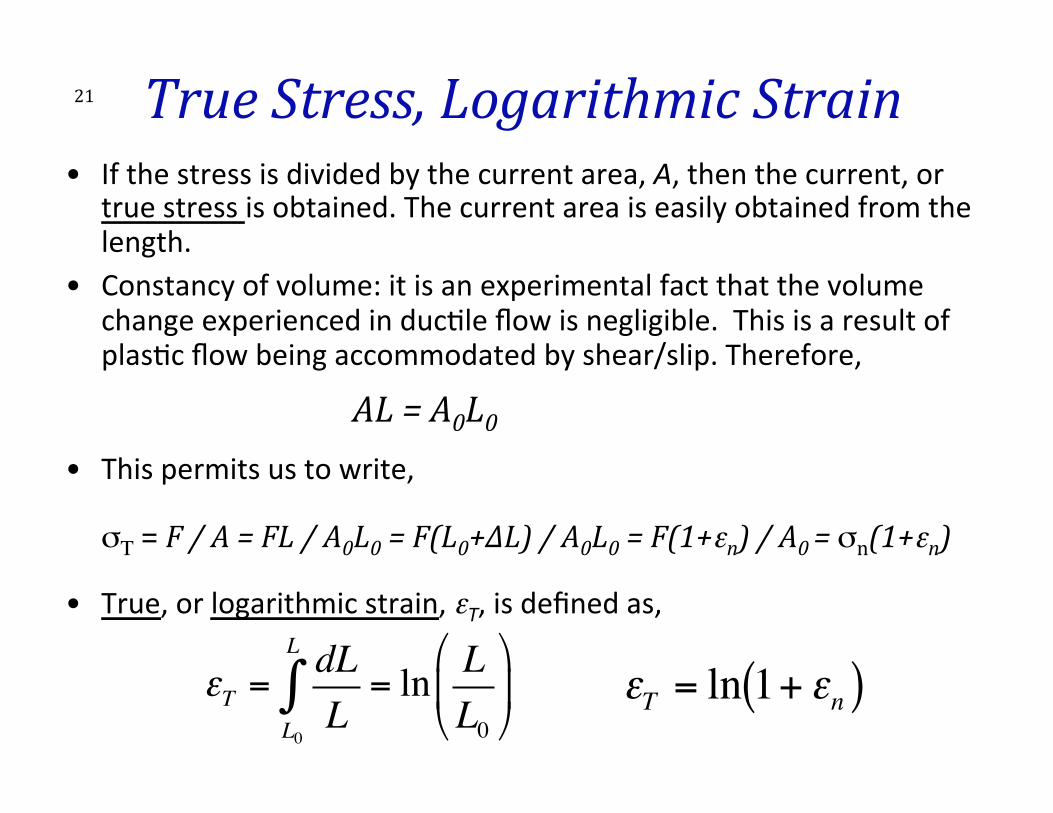
21 True Stress, Logarithmic Strain • If the stress is divided by the current area, A, then the current, or
true stress is obtained. The current area is easily obtained from the length.
• Constancy of volume: it is an experimental fact that the volume change experienced in duc>le flow is negligible. This is a result of plas>c flow being accommodated by shear/slip. Therefore,
AL = A0L0
• This permits us to write, σΤ = F / A = FL / A0L0 = F(L0+∆L) / A0L0 = F(1+εn) / A0 = σn(1+εn)
• True, or logarithmic strain, εT, is defined as,
εT =dLLL0
L
∫ = ln LL0
"
#$
%
&'
€
εT = ln 1+ εn( )

22 Why is Ductility important? • Why do materials exhibit duc>lity? The reason for duc>lity in metals is that they work harden. – The key concept is the re-‐distribu*on of strain. That is to say, if one sub-‐region of a material hardens as a result of the accumula>on of disloca>ons then its load carrying capacity is higher than that of the neighboring regions. More specifically, the flow stress is lower in the non-‐hardened regions than in the hardened region. Therefore plas>c flow (i.e. the strain rate) is larger in the non-‐hardened region(s) and, in effect, the strain is redistributed to a different part of the specimen. • Many polymer systems also exhibit bulk duc>lity because the long chain molecules are present in folded form, either regularly arranged as in the semi-‐crystalline polymers, or irregularly as in the amorphous polymers. This conforma>on of the long chain molecules allows for considerable stretching during plas>c deforma>on and oeen to a few hundred percent.

23 Why is Ductility [inite? • Duc>lity is limited because the rate of work hardening decreases
with strain. – Straining does not con>nue indefinitely. There are several ways in which plas>c
deforma>on will cease; collec>vely, the various phenomena are discussed as fracture. One limit to straining comes when the material exhausts its ability to redistribute strain. This exhaus>on is dependent on the geometry of the test, however. For example, the tensile deforma>on results in a steady decrease in the cross sec>on which sets up a compe>>on between strain hardening and geometric soeening from the perspec>ve of load carrying capacity of a given element of material. When the strain hardening no longer "keeps up with" the geometric soeening then strain redistribu>on ceases and a neck will start to form.
– In certain polymers, however, the load carrying capacity keeps on increasing because of the increasing alignment of the fibers. This leads to a stress-‐strain curve that can accelerate and thus extremely large strains to failure are found.
• Post-‐necking strain is also important and varies extensively between different materials (to be discussed).
24
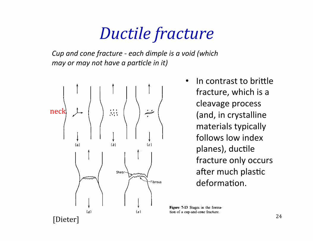
Ductile fracture
• In contrast to bri3le fracture, which is a cleavage process (and, in crystalline materials typically follows low index planes), duc>le fracture only occurs aeer much plas>c deforma>on.
Cup and cone fracture -‐ each dimple is a void (which may or may not have a par7cle in it)
[Dieter]
neck
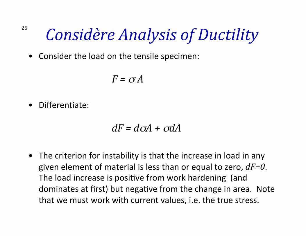
25 Considère Analysis of Ductility • Consider the load on the tensile specimen:
F = σ A
• Differen>ate:
dF = dσA + σdA
• The criterion for instability is that the increase in load in any given element of material is less than or equal to zero, dF=0. The load increase is posi>ve from work hardening (and dominates at first) but nega>ve from the change in area. Note that we must work with current values, i.e. the true stress.
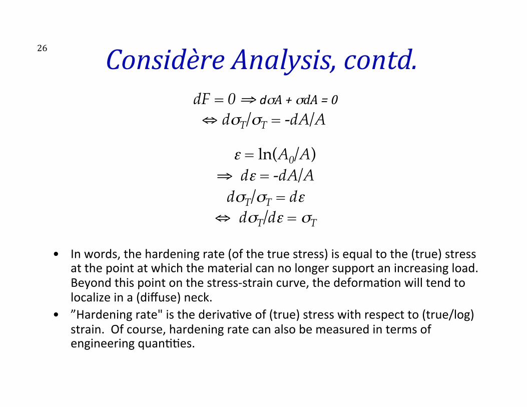
26 Considère Analysis, contd. dF = 0 ⇒ dσA + σdA = 0 ⇔ dσT/σT = -dA/A
ε = ln(A0/A)"
⇒ dε = -dA/A"dσT/σT = dε
⇔ dσT/dε = σT�
• In words, the hardening rate (of the true stress) is equal to the (true) stress at the point at which the material can no longer support an increasing load. Beyond this point on the stress-‐strain curve, the deforma>on will tend to localize in a (diffuse) neck.
• ”Hardening rate" is the deriva>ve of (true) stress with respect to (true/log) strain. Of course, hardening rate can also be measured in terms of engineering quan>>es.
27 Considère’s Criterion
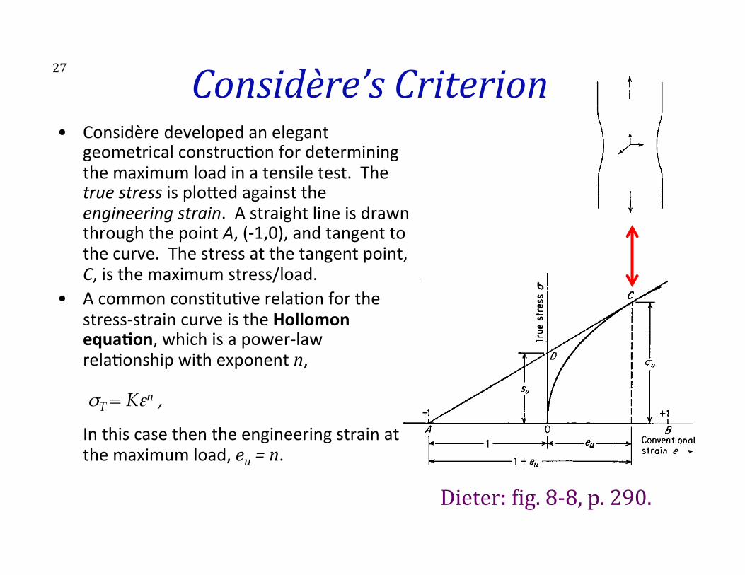
Dieter: Oig. 8-‐8, p. 290.
• Considère developed an elegant geometrical construc>on for determining the maximum load in a tensile test. The true stress is plo3ed against the engineering strain. A straight line is drawn through the point A, (-‐1,0), and tangent to the curve. The stress at the tangent point, C, is the maximum stress/load.
• A common cons>tu>ve rela>on for the stress-‐strain curve is the Hollomon equa*on, which is a power-‐law rela>onship with exponent n, σT = Kεn ,��In this case then the engineering strain at the maximum load, eu = n.
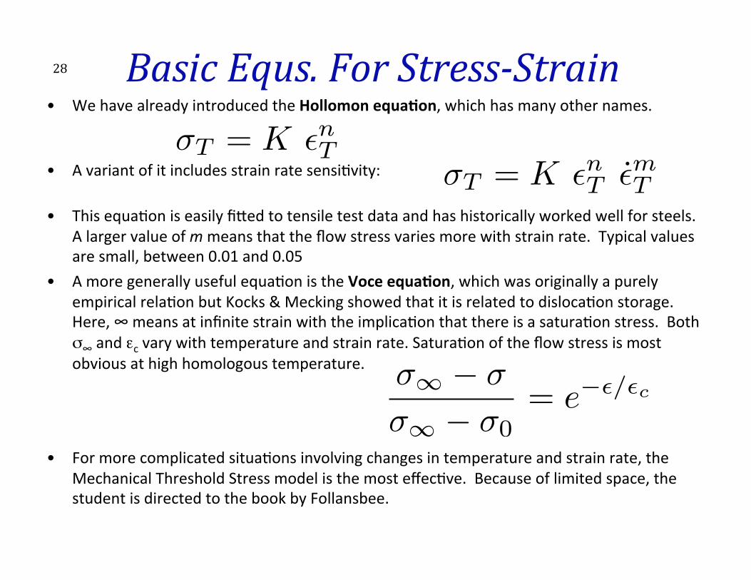
Basic Equs. For Stress-‐Strain • We have already introduced the Hollomon equa*on, which has many other names.
#
• A variant of it includes strain rate sensi>vity:
• This equa>on is easily fi3ed to tensile test data and has historically worked well for steels. A larger value of m means that the flow stress varies more with strain rate. Typical values are small, between 0.01 and 0.05
• A more generally useful equa>on is the Voce equa*on, which was originally a purely empirical rela>on but Kocks & Mecking showed that it is related to disloca>on storage. Here, ∞ means at infinite strain with the implica>on that there is a satura>on stress. Both σ∞ and εc vary with temperature and strain rate. Satura>on of the flow stress is most obvious at high homologous temperature.
• For more complicated situa>ons involving changes in temperature and strain rate, the Mechanical Threshold Stress model is the most effec>ve. Because of limited space, the student is directed to the book by Follansbee.
28
�T = K ✏nT ✏̇mT�T = K ✏nT
�1 � �
�1 � �0= e�✏/✏c

29 Ductility-‐Microstructure • How does microstructure influence duc>lity? • Provided that disloca>ons move easily through the material and macroscopic instabili>es (such as necking) do not intervene, duc>lity can be very large.
• Any microstructural element that leads to local cracking will tend to lower duc>lity by decreasing the load carrying capacity of the material.
• Inclusions, second phase par>cles, grain boundaries, for example, are all poten>al fracture sites.
• Qualita>vely, cleaner, purer materials have higher duc>lity.
30 Summary of Plastic Deformation • The following points are useful as a summary of important
features of plas>city from a material perspec>ve. • Stress-‐strain curves provide a straighworward way to measure
yield stress, ul>mate tensile stress and duc>lity. • The maximum load and maximum uniform elonga>on are
predictable from the stress-‐strain curve (e.g. power law), which is known as Considère’s construc>on.
• Single crystal behavior reflects the anisotropy of the crystal for both elas>c (see lecture on elas>city) and plas>c behavior.
• Single crystal plas>c behavior is controlled by disloca>on movement; deforma>on twinning can supplement disloca>on glide, however, and is more common in lower symmetry crystals.
• The presence of disloca>ons that can glide at low (cri>cal resolved) shear stresses means that metals yield plas>cally at stresses far below the theore>cal strength.
31 Summary • The concept of strength as a material property has been
explored. • Basic mechanical quan>>es and proper>es (stress, strain,
strength, hardness, duc>lity) have been defined and illustrated with respect to prac>cal methods for measurement.
• Basic equa>ons that can be used to describe stress-‐strain rela>ons are described.
• The “Considère Criterion” that relates the diffuse necking to the work hardening rate of a material has been explained.
• Analysis of tensile tests has been described, including the compliance correc>on.
32 References • Materials Principles & Prac>ce, Bu3erworth Heinemann, Edited
by C. Newey & G. Weaver. • G.E. Dieter, Mechanical Metallurgy, McGrawHill, 3rd Ed. • D. Hull and D. J. Bacon (1984). Introduc>on to Disloca>ons,
Oxford, UK, Pergamon. • T. H. Courtney (2000). Mechanical Behavior of Materials, Boston,
McGraw-‐Hill. • P.O. Ke3unen & V.T. Kuokkala (2002). Plas>c Deforma>on and
Strain Hardening, Zurich, Switzerland, Trans Tech Publica>ons. • P.S. Follansbee (2014). Fundamentals of Strength, Warrendale,
PA, Wiley.