Embed Size (px)
Citation preview
International Journal of the Physical Sciences Vol. 5 (2), pp. 116-131, February, 2010 Available online at http://www.academicjournals.org/IJPS ISSN 1992 - 1950 © 2010 Academic Journals
Full Length Research Paper
Improving out-of-plane strength and ductility of unreinforced masonry walls in low-rise buildings by
centrally applied FRP strip
Mürsel Erdal
Gazi University, Technical Education Faculty, Construction Department, 06500, Teknikokullar, Ankara, Turkey. E-mail: [email protected]. Tel: +90 312 2028870. Fax: +90 312 2120059.
Accepted 30 December, 2009
The seismic collapse of a low-rise unreinforced masonry (URM) building is initiated by the out-of-plane failure of walls at roof level. The theoretical basis of this engineering problem is presented. The available strength and ductility of a URM wall is presented, which was tested under reversed loads to simulate seismic effects. It was seen that both ductility and strength need to be improved. Another geometrically similar URM test wall which is retrofitted by FRP was constructed. Test results showed significant increases in both strength and ductility. The final failure came by the tensile rupture of the FRP strip. Keywords: Earthquake, masonry, seismic, out-of-plane, FRP.
INTRODUCTION On August 17, 1999, a major earthquake hit the Marmara region, the north western part of Turkey, including �stanbul, measuring Mw = 7.4 on the Richter scale. According to official statistics, 17488 people were killed and 112724 buildings either collapsed or were heavily damaged.
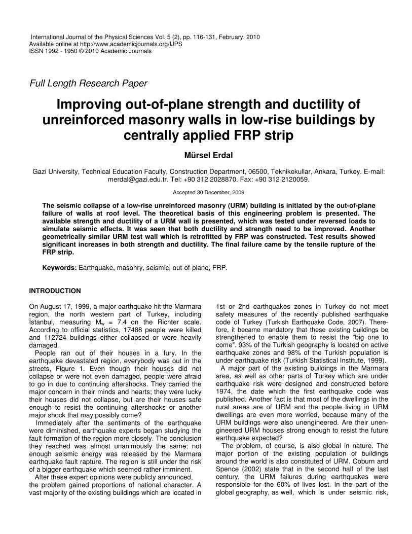
People ran out of their houses in a fury. In the earthquake devastated region, everybody was out in the streets, Figure 1. Even though their houses did not collapse or were not even damaged, people were afraid to go in due to continuing aftershocks. They carried the major concern in their minds and hearts; they were lucky their houses did not collapse, but are their houses safe enough to resist the continuing aftershocks or another major shock that may possibly come?
Immediately after the sentiments of the earthquake were diminished, earthquake experts began studying the fault formation of the region more closely. The conclusion they reached was almost unanimously the same; not enough seismic energy was released by the Marmara earthquake fault rapture. The region is still under the risk of a bigger earthquake which seemed rather imminent.
After these expert opinions were publicly announced, the problem gained proportions of national character. A vast majority of the existing buildings which are located in
1st or 2nd earthquakes zones in Turkey do not meet safety measures of the recently published earthquake code of Turkey (Turkish Earthquake Code, 2007). There-fore, it became mandatory that these existing buildings be strengthened to enable them to resist the “big one to come”. 93% of the Turkish geography is located on active earthquake zones and 98% of the Turkish population is under earthquake risk (Turkish Statistical Institute, 1999).
A major part of the existing buildings in the Marmara area, as well as other parts of Turkey which are under earthquake risk were designed and constructed before 1974, the date which the first earthquake code was published. Another fact is that most of the dwellings in the rural areas are of URM and the people living in URM dwellings are even more worried, because many of the URM buildings were also unengineered. Are their unen-gineered URM houses strong enough to resist the future earthquake expected?
The problem, of course, is also global in nature. The major portion of the existing population of buildings around the world is also constituted of URM. Coburn and Spence (2002) state that in the second half of the last century, the URM failures during earthquakes were responsible for the 60% of lives lost. In the part of the global geography, as well, which is under seismic risk,
Erdal 117
Figure 1. Marmara Earthquake and its devastation.
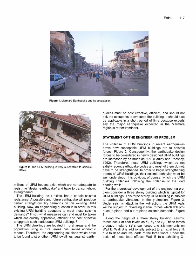
Figure 2. The URM building is very susceptible to seismic attack.
millions of URM houses exist which are not adequate to resist the “design earthquake” and have to be, somehow, strengthened.
The URM building, as it exists, has a certain seismic resistance. A possible and future earthquake will produce certain strength/ductility demands on this existing URM building. Now, an engineering question is in order: is this existing URM building adequate to meet these seismic demands? If not, what measures can and must be taken which are quickly applicable, efficient and cost effective to upgrade such inadequate URM buildings?
The URM dwellings are located in rural areas and the population living in rural areas has limited economic means. Therefore, the engineering solutions which have to be found to strengthen URM dwellings against earth-
quakes must be cost effective, efficient, and should not ask the occupants to evacuate the building. It should also be applicable in a short period of time because experts say the major earthquake expected in the Marmara region is rather imminent. STATEMENT OF THE ENGINEERING PROBLEM The collapse of URM buildings in recent earthquakes prove how susceptible URM buildings are to seismic forces, Figure 2. Consequently, the earthquake design forces to be considered in newly designed URM buildings are increased by as much as 50% (Paulay and Priestley, 1992). Therefore, those URM buildings which do not satisfy recent earthquake codes and most of them do not, have to be strengthened. In order to begin strengthening efforts of URM buildings, their seismic behavior must be well understood. It is obvious, of course, which the URM building collapses following the collapse of the load bearing walls.
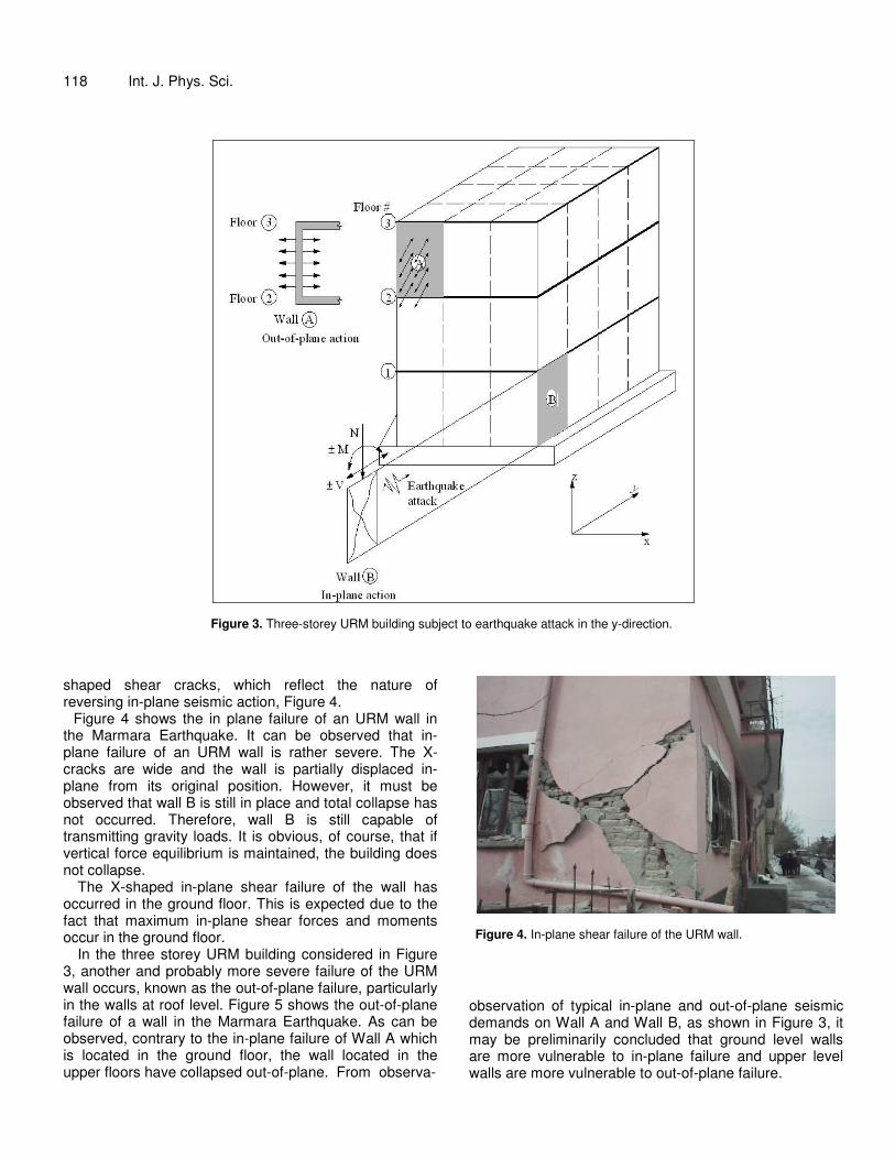
For the theoretical development of the engineering pro-blem consider a three storey building which is typical for URM buildings. This three storey URM building is subject to earthquake vibrations in the y-direction, Figure 3. Under seismic attack in the y-direction, the URM walls will be subject to reversing inertial forces which will pro-duce in-plane and out-of-plane seismic demands, Figure 3.
Along the height of a three storey building, seismic forces occur at floor levels as F1, F2 and F3. These forces produce in-plane ±V shear forces and ±M moments on Wall B. Wall B is additionally subject to an axial force N, due to dead and live loads of the three floors. Under the action of these load effects, Wall B fails exhibiting X-
118 Int. J. Phys. Sci.
Figure 3. Three-storey URM building subject to earthquake attack in the y-direction.
shaped shear cracks, which reflect the nature of reversing in-plane seismic action, Figure 4.
Figure 4 shows the in plane failure of an URM wall in the Marmara Earthquake. It can be observed that in-plane failure of an URM wall is rather severe. The X-cracks are wide and the wall is partially displaced in-plane from its original position. However, it must be observed that wall B is still in place and total collapse has not occurred. Therefore, wall B is still capable of transmitting gravity loads. It is obvious, of course, that if vertical force equilibrium is maintained, the building does not collapse.
The X-shaped in-plane shear failure of the wall has occurred in the ground floor. This is expected due to the fact that maximum in-plane shear forces and moments occur in the ground floor.
In the three storey URM building considered in Figure 3, another and probably more severe failure of the URM wall occurs, known as the out-of-plane failure, particularly in the walls at roof level. Figure 5 shows the out-of-plane failure of a wall in the Marmara Earthquake. As can be observed, contrary to the in-plane failure of Wall A which is located in the ground floor, the wall located in the upper floors have collapsed out-of-plane. From observa-
Figure 4. In-plane shear failure of the URM wall.
observation of typical in-plane and out-of-plane seismic demands on Wall A and Wall B, as shown in Figure 3, it may be preliminarily concluded that ground level walls are more vulnerable to in-plane failure and upper level walls are more vulnerable to out-of-plane failure.

Erdal 119
Figure 5. Out-of-plane failure of an URM wall in a low-rise multi-storey building.
Figure 6. Mathematical model of a 3-storey building for earthquake attack coming from the y-direction.
THEORETICAL DEVELOPMENT OF DETERMINING THE SEISMIC DEMANDS FOR STRENGTHENING EFFORTS OF URM BUILDINS The URM building shown in Figure 3 can be mathematically modeled for an earthquake attack. In the
y-direction, Ey as shown in Figure 6. Subject to earthquake, the three storey URM building
undergoes sway which can be expressed as y(t). The variation of the sway profile from base to roof level can be differentiated once with respect to time t to obtain the velocity profile and differentiated twice to obtain the acce-
120 Int. J. Phys. Sci.
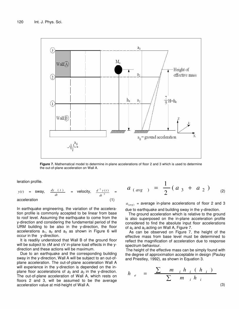
Figure 7. Mathematical model to determine in-plane accelerations of floor 2 and 3 which is used to determine the out-of-plane acceleration on Wall A.
leration profile.
)(ty = sway, dt
tdy )( = velocity, 2
2 )(
dt
tyd =
acceleration (1) In earthquake engineering, the variation of the accelera-tion profile is commonly accepted to be linear from base to roof level. Assuming the earthquake to come from the y-direction and considering the fundamental period of the URM building to be also in the y-direction, the floor accelerations a1, a2 and a3 as shown in Figure 6 will occur in the y-direction.
It is readily understood that Wall B of the ground floor will be subject to ±M and ±V in-plane load effects in the y-direction and these actions will be maximum.
Due to an earthquake and the corresponding building sway in the y-direction, Wall A will be subject to an out-of-plane acceleration. The out-of-plane acceleration Wall A will experience in the y-direction is depended on the in-plane floor accelerations of a2 and a3 in the y-direction. The out-of-plane acceleration of Wall A, which rests on floors 2 and 3, will be assumed to be the average acceleration value at mid-height of Wall A.
)(21
23)( aaa avg += (2)
)(avga = average in-plane accelerations of floor 2 and 3
due to earthquake and building sway in the y-direction. The ground acceleration which is relative to the ground
is also superposed on the in-plane acceleration profile considered to find the absolute input floor accelerations of a2 and a3 acting on Wall A, Figure 7.
As can be observed on Figure 7, the height of the effective mass from base level must be determined to reflect the magnification of acceleration due to response spectrum behaviour. The height of the effective mass can be simply found with the degree of approximation acceptable in design (Paulay and Priestley, 1992), as shown in Equation 3.
�
�=ii
iiie hm
hhmh
)(
(3)

For the case of the considered URM building of 3 stories high which has equal floor masses and equal floor heights, he becomes
)3
()32
()(
)3
)(3
()32
)(32
())((
HmHmHm
HHmHHmHHm
he++
++=
)(97
Hh e =
(4)
In design codes to obtain the response spectrum acceleration (International Building Code), the maximum ground acceleration multiplier is commonly assumed to be 2.5, defined as the Response Spectrum Acceleration Coefficient. Then, the acceleration of Floor 2, Floor 3 and a(avg) in the y-direction becomes as follows.
)91
1)(5.2(2 += gaa
(5)
)79
)(5.2(3 gaa =
(6)
ggggavg aaaaa 0.3)2.1(5.221
)11.129.1(5.221
)910
79
(5.2)( ==+=+=
(7)
This a(avg), can be used to determine the out-of-plane acceleration of Wall A. The average acceleration a(avg) is the input out-of-plane acceleration for Wall A. Wall A will take a(avg) as the input acceleration and will further magnify it as a response behavior depending on the out-of-plane fundamental period of Wall A. The action is similar to the magnification of the effective ground acceleration in the direction of the fundamental period of the building, as it rises up to the center of effective mass of the building (Uniform Building Code, 1997).
An engineering question is now in order: what is the proper acceleration response spectrum coefficient to be used to obtain the out-of-plane acceleration of Wall A? After reviewing inelastic analyses data, Paulay and Priestley (1992) suggest that a factor of 2 can properly be adopted. Consequently, the out-of-plane acceleration of Wall A is
)(),( 0.2 avgplaneofoutA aa =−−
(8)
For an effective ground acceleration of 0.4 g which is commonly accepted in earthquake zone 1, the out-of-
Erdal 121 plane acceleration of Wall A becomes as follows.
gplaneofoutA aa 0.6),( =−−
(9)
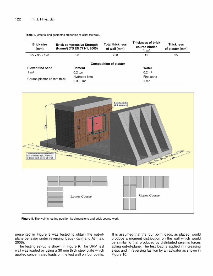
It can be easily observed from Equation 8 that the most vulnerable wall to out-of-plane ailure is the wall at roof level because a(avg) is maximum at this level. This level, observation agrees well with the out-of-plane failure of wall shown in Figure 5. It is now proper to restate the engineering problem. a) Is Wall A strong enough to resist the out-of-plane seismic demands to be imposed by the future earthquake? b) If not, how can wall A be strengthened? In order to be able to answer the above questions, the strength and ductility of existing URM walls having different material and geometric compositions must be determined. Then, the seismic strength and ductility demands imposed by the design earthquake must be calculated. A critical comparison strength and ductility of the existing URM wall with those imposed by the design earthquake will enable the design engineer to decide if the existing URM wall is safe or not. EXPERIMENTAL ASSESSMENT OF THE OUT-OF-PLANE BEHAVIOR OF A TYPICAL UNSTRENGTHENED URM WALL The seismic behaviour of a typical unstrengthened URM wall has been experimentally assessed (Kanit and Atimtay, 2006), as shown in Figure 8.
Two parameters were considered to be important and are therefore included in the experimental program. Firstly, the test specimen was designed to have a one-to-one (1/1) scale to eliminate the size effect which could mask or complicate the true seismic behaviour. Secondly, the test specimen is to be subjected to reversing loads to impose the action of seismic inertial forces more realistically. The material and geometric properties of the wall tested are as shown in Table 1. The test wall in the testing position ready to be tested and its overall dimensions with the brick course work are shown in Figure 8.
The front and back surfaces of the test wall were plastered. The concrete floor on top of the test wall was made of C16 concrete, which was meant to represent common practice. THE TEST PROCEDURE The URM test specimen, the properties of which are pre-
122 Int. J. Phys. Sci.
Table 1. Material and geometric properties of URM test wall.
Brick size (mm)
Brick compressive Strength (N/mm²) (TS EN 771-1, 2005)
Total thickness of wall (mm)
Thickness of brick course binder
(mm)
Thickness of plaster (mm)
55 x 95 x 190 5.0 250 12 25
Composition of plaster Sieved find sand Cement Water 1 m³ 0.2 ton 0.2 m³
Hydrated lime Fine sand Course plaster 15 mm thick
0.330 m³ 1 m³
Figure 8. The wall in testing position its dimensions and brick course work.
presented in Figure 8 was tested to obtain the out-of-plane behavior under reversing loads (Kanit and Atimtay, 2006).
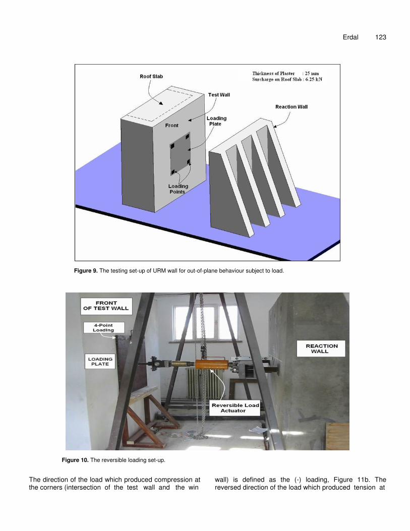
The testing set-up is shown in Figure 9. The URM test wall was loaded by using a 30 mm thick steel plate which applied concentrated loads on the test wall on four points.
It is assumed that the four point loads, as placed, would produce a moment distribution on the wall which would be similar to that produced by distributed seismic forces acting out-of-plane. The test load is applied in increasing steps and in reversing fashion by an actuator as shown in Figure 10.
Erdal 123
Figure 9. The testing set-up of URM wall for out-of-plane behaviour subject to load.
Figure 10. The reversible loading set-up.
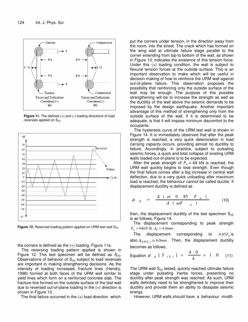
The direction of the load which produced compression at the corners (intersection of the test wall and the win
wall) is defined as the (-) loading, Figure 11b. The reversed direction of the load which produced tension at
124 Int. J. Phys. Sci.
Figure 11. The defined (+) and (-) loading directions of load reversals applied on S(0).
Figure 12. Reserved loading pattern applied on URM test wall S(0).
the corners is defined as the (+) loading, Figure 11a.
The reversing loading pattern applied is shown in Figure 12. This test specimen will be defined as S(0). Observations of behavior of S(0) subject to load reversals are important in making strengthening decisions. As the intensity of loading increased, fracture lines (Hendry, 1998) formed at both faces of the URM wall similar to yield lines which form on a reinforced concrete slab. The fracture line formed on the outside surface of the test wall due to reversed out-of-plane loading in the (+) direction is shown in Figure 13.
The final failure occurred in the (+) load direction which
put the corners under tension, in the direction away from the room, into the street. The crack which has formed on the wing wall at ultimate failure stage parallel to the corner extending from top to bottom of the wall, as shown in Figure 13, indicates the existence of this tension force. Under this (+) loading condition, the wall is subject to flexural tension forces at the outside surface. This is an important observation to make which will be useful in decision making of how to reinforce the URM wall against out-of-plane failure. This observation proposes the possibility that reinforcing only the outside surface of the wall may be enough. The purpose of this possible strengthening will be to increase the strength as well as the ductility of the wall above the seismic demands to be imposed by the design earthquake. Another important advantage of this method of strengthening only from the outside surface of the wall, if it is determined to be adequate, is that it will impose minimum discomfort to the occupants.
The hysteresis curve of the URM test wall is shown in Figure 14. It is immediately observed that after the peak strength is reached, a very quick deterioration in load carrying capacity occurs, providing almost no ductility to failure. Accordingly, in practice, subject to pulsating seismic forces, a quick and total collapse of existing URM walls loaded out-of-plane is to be expected.
After the peak strength of Fu = 64 kN is reached, the URM wall quickly begins to lose strength. Even though the final failure comes after a big increase in central wall deflection, due to a very quick unloading after maximum load is reached, the behaviour cannot be called ductile. If displacement ductility is defined as
)()85.0(
u
u
atFFat
∆∆µ ∆ = (10)
then, the displacement ductility of the test specimen S(0) is as follows, Figure 14.
The displacement corresponding to peak strength kNFu 64= is mmu 0.4=∆ .
The displacement corresponding to uF85.0 is also mm
uF 0.4)85.0( ≅∆ . Then, the displacement ductility
becomes as follows,
Equation 0.14
0.4][ )0( ==S∆µ
(11)
The URM wall S(0) tested, quickly reached ultimate failure stage under pulsating inertia forces, presenting no ductility after peak strength was reached. As such, URM walls definitely need to be strengthened to improve their ductility and provide them an ability to dissipate seismic energy.
However, URM walls should have a behaviour modifi-
Erdal 125
Figure 13. Crack formation at outside surface of URM test wall at final failure.
Figure 14. Hysteresis relationship of URM test wall.
126 Int. J. Phys. Sci.
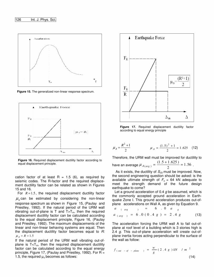
Figure 15. The generalized non-linear response spectrum.
Figure 16. Required displacement ductility factor according to equal displacement principle.
cation factor of at least R = 1.5 (6), as required by seismic codes. The R-factor and the required displace-ment ductility factor can be related as shown in Figures 15 and 16.
For 5.1=R , the required displacement ductility factor
∆µ can be estimated by considering the non-linear response spectrum as shown in Figure 15, (Paulay and Priestley, 1992). If the natural period of the URM wall vibrating out-of-plane is T and T>Tm, then the required displacement ductility factor can be calculated according to the equal displacement principle, Figure 16, (Paulay and Priestley, 1992). The maximum displacements of the linear and non-linear behaving systems are equal. Then the displacement ductility factor becomes equal to R:
5.1== R∆µ If the natural period of the URM wall vibrating out-of-plane is T<Tm, then the required displacement ductility factor can be calculated according to the equal energy principle, Figure 17, (Paulay and Priestley, 1992). For R = 1.5, the required µ� becomes as follows:
Figure 17. Required displacement ductility factor according to equal energy principle
212 += R
∆µ 625.12
1)5.1( 2
=+=∆µ (12)
Therefore, the URM wall must be improved for ductility to
have an average 56.12
)625.15.1()( =+=avg∆µ .
As it exists, the ductility of S(0) must be improved. Now, the second engineering question should be asked: is the available ultimate strength of Fu = 64 kN adequate to meet the strength demand of the future design earthquake to come?
Let a ground acceleration of 0.4 g be assumed, which is the commonly accepted ground acceleration in Earth-quake Zone I. This ground acceleration produces out-of-plane accelerations on Wall A, as given by Equation 9.
gavg aa 0.6)( =
gga avg 4.2)4.0(0.6)( == (13) The acceleration forcing the URM wall A to fail out-of-plane at roof level of a building which is 3 stories high is 2.4 g. This out-of-plane acceleration will create out-of-plane inertia forces acting perpendicular to the surface of the wall as follow:
2)( /)4.2( mkNg
gw
f planeofout =−−
(14)
w = weight of wall of unit area of bw =250 mm in thickness Unit weight of the wall material is assumed to be 20 kN/m3.
2/5)0.125.0(20 mkNw =××= (15) Out-of-plane distributed inertia force on wall A is
23)( /12)4.2(/5 mkNmkNf planeofout ==−− . (16)
Due to a ground acceleration of ag = 0.4 g, a URM wall located at roof level of a 3 storey building will be subject to distributed out-of-plane forces of 12 kN/m². The wall tested with geometric dimensions of 2.1 x 2.7 m must be able to resist a total out-of-plane strength demand of FE.
kNmkNF E 04.68)1.27.2(/12 2 =×= (17) Can the plain unreinforced URM wall of one brick thickness resist this load demand? Available strength as obtained from experiment:
kNSF 64][ )0( = .
Strength demand as obtained from calculations:
kNFE 68= . Strength demand is greater than the available strength:
RE FF > . The out-of-plane seismic distributed strength demand cannot be met by the unreinforced wall having geometric and material properties as S(0).
The displacement ductility should be improved with priority. If the ductility demand µA, as reflected by R = 1.5 was met, then FE equal to F(S(0)) should be considered enough. The two strength values are close, but nevertheless the strength demand exceeds the available capacity and should be also be improved.
The engineering conclusion reached from the behaviour of S(0) under reversing and step-wise increasing loads is that both the displacement ductility and strength need improvement. METHODS OF IMPROVING THE OUT-OF-PLANE BEHAVIOUR OF URM WALLS AGAINST SEISMIC FORCES AVAILABLE IN LITERATURE Saadatmanesh (1997) reports that URM walls reinforced by epoxy bonded FRP fabrics showed significant improvements in behaviour.
Gilstrap and Dolan (1998) present a general discussion on out-of-plane bending of FRP-reinforced masonry walls. Examples are provided of structure reinforcement and repair by the use of fiber based systems. Test results are also included.
Erdal 127 The most commonly applied traditional strengthening method is applying mesh reinforcement over the surface of the wall and then shotcreting. Additional possibilities are applying buttresses and vertical or diagonal beam elements that are concrete or steel. Other possibilities also exist which are less frequently applied. The main drawbacks of these methods are that they are time consuming, create considerable discomfort to the occupants and have sig-nificant cost. They also present aesthetic problems (Abrams, 2000).
Hamoush et al. (2002) applied FRP composites externally to eighteen compact wall panels and evaluated the out-of-plane shear strength. The area of externally bonded FRP, layout configurations and reinforcement ratios were main parameters of the study. They concluded that the shear strength of the concrete masonry wall system is constant over the range of variables tested. They also stated that the code defined shear strength may not be as conservative as assumed.
Valluzzi et al. (2002) studied experimentally brick masonry panels strengthened by FRP laminates. It was found out that FRP reinforcement applied only at one side of the panels provided a less brittle failure and a noticeable ultimate capacity increase.
Galati et al. (2006) studied the behaviour of 15 URM walls strengthened with FRP bars. Using their own test data and others found in technical literature, they developed criteria that can be used in the development of design guidelines.
Turco et al. (2006) presented the successful use of near surface mounted FRP bars for strengthening URM walls. They showed the potential of the technique for retrofitting masonry structures: the installation time is minimal, the appearance is preserved, the capacity markedly increase and the behavior at failure more ductile.
El-Dakhakhni et al. (2006) tested URM walls in steel frames reinforced by FRP. They found that the composite laminates increased the stiffness and strength and prevented the spalling of URM walls.
Mosallam (2007) presented results of a study on evaluating the out-of-plane flexural behavior of two FRP composite systems for strengthening unreinforced red brick masonry walls. Full scale experimental results confirmed the effectiveness of the FRP composite strengthening systems in upgrading the out-of-plane flexural structural performance.
Hamed and Rabinovitch (2007) studied analytically the out-of-plane behavior of URM walls strengthened with externally bonded FRP strip. They explained the interaction between the variables and quantitative aspects of FRP strengthened walls.
Pepanicolozou et al. (2008) have compared textile reinforced mortar (TRM) with FRP in increasing the strength and deformability of URM subject to cyclic loading. They concluded that, TRM may result in higher effectiveness.
The development of FRPs presents new possibilities. Their application is quite easy and quick and they can also be cost effective. However, because they are rather newly developed, their performance must be evaluated by tests. Tests to evaluate the applicability and effectiveness of using FRPs, as a method to strengthening URM walls against out-of-plane and in-plane failures are numerous. STRENGTHENING AND IMPROVING DUCTILITY OF THE URM WALL BY FRP APPLICATION In seismic strengthening of structures, the commonly accepted basic philosophy is also adopted here: the strengthening efforts must be cost efficient and must result in the least discomfort to the occupants. If possible, the occupants should not be asked to evacuate the building.
From a review of the existing technical literature, it was seen that the use of FRP as a strengthening method is a very attractive
128 Int. J. Phys. Sci.
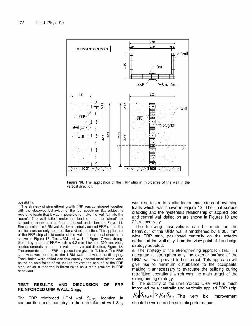
Figure 18. The application of the FRP strip in mid-centre of the wall in the vertical direction.
possibility.
The strategy of strengthening with FRP was considered together with the observed behaviour of the test specimen S(0) subject to reversing loads that it was impossible to make the wall fail into the “room”. The wall failed under (+) loading into the “street” by subjecting the exterior surface of the wall under tension, Figure 11. Strengthening the URM wall S(0) by a centrally applied FRP strip at the outside surface only seemed like a viable solution. The application of the FRP strip at mid-center of the wall in the vertical direction is shown in Figure 18. The URM test wall of Figure 7 was streng-thened by a strip of FRP which is 0.2 mm thick and 300 mm wide, applied centrally on the test wall in the vertical direction, Figure 18. The properties of the FRP strip used are given in Table 2. The FRP strip was wet bonded to the URM wall and waited until drying. Then, holes were drilled and five equally spaced steel plates were bolted on both faces of the wall to prevent the peel-off of the FRP strip, which is reported in literature to be a main problem in FRP behaviour. TEST RESULTS AND DISCUSSION OF FRP REINFORCED URM WALL, S(FRP) The FRP reinforced URM wall S(FRP), identical in composition and geometry to the unreinforced wall S(0),
was also tested in similar incremental steps of reversing loads which was shown in Figure 12. The final surface cracking and the hysteresis relationship of applied load and central wall deflection are shown in Figures 19 and 20, respectively.
The following observations can be made on the behaviour of the URM wall strengthened by a 300 mm wide FRP strip, positioned centrally on the exterior surface of the wall only, from the view point of the design strategy adopted. a. The strategy of the strengthening approach that it is adequate to strengthen only the exterior surface of the URM wall was proved to be correct. This approach will give rise to minimum disturbance to the occupants, making it unnecessary to evacuate the building during retrofitting operations which was the main target of the strengthening strategy. b. The ductility of the unreinforced URM wall is much improved by a centrally and vertically applied FRP strip:
[ ] [ ])0()( SS FRP ∆∆ µµ > .This very big improvement
should be welcomed in seismic performance.
Erdal 129
Table 2. The properties of FRP used for seismic strengthening of the URM test wall.
Tension strength characteristic (MPa) ASTM 3039
Modulus of elasticity characteristic (MPa)
Rupture strain �u
(%) Width (mm) (standard) Fiber
3430 230000 1.5 300 Unidirectional carbon fiber 165 micron thick
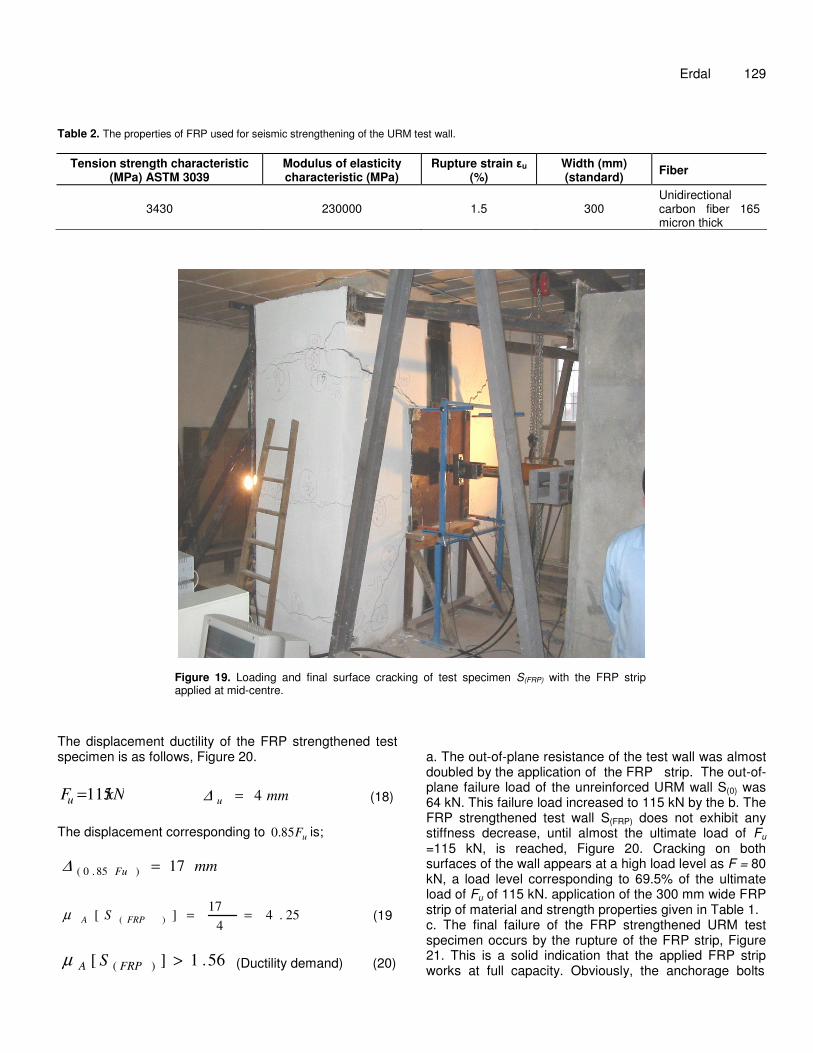
Figure 19. Loading and final surface cracking of test specimen S(FRP) with the FRP strip applied at mid-centre.
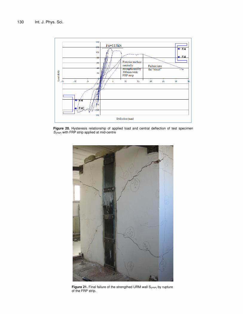
The displacement ductility of the FRP strengthened test specimen is as follows, Figure 20.
kNFu 115= mmu 4=∆ (18) The displacement corresponding to uF85.0 is;
mmFu 17)85.0( =∆
25.44
17][ )( ==FRPA Sµ (19
56.1][ )( >FRPA Sµ (Ductility demand) (20)
a. The out-of-plane resistance of the test wall was almost doubled by the application of the FRP strip. The out-of- plane failure load of the unreinforced URM wall S(0) was 64 kN. This failure load increased to 115 kN by the b. The FRP strengthened test wall S(FRP) does not exhibit any stiffness decrease, until almost the ultimate load of Fu
=115 kN, is reached, Figure 20. Cracking on both surfaces of the wall appears at a high load level as F = 80 kN, a load level corresponding to 69.5% of the ultimate load of Fu of 115 kN. application of the 300 mm wide FRP strip of material and strength properties given in Table 1. c. The final failure of the FRP strengthened URM test specimen occurs by the rupture of the FRP strip, Figure 21. This is a solid indication that the applied FRP strip works at full capacity. Obviously, the anchorage bolts
130 Int. J. Phys. Sci.
Figure 20. Hysteresis relationship of applied load and central deflection of test specimen S(FRP) with FRP strip applied at mid-centre
Figure 21. Final failure of the strengthed URM wall S(FRP) by rupture of the FRP strip.
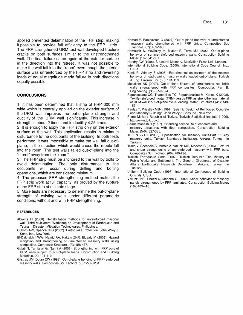
applied prevented delamination of the FRP strip, making it possible to provide full efficiency to the FRP strip. The FRP strengthened URM test wall developed fracture cracks on both surfaces similar to the unstrengthened wall. The final failure came again at the exterior surface in the direction into the “street”. It was not possible to make the wall fail into the “room” even though the interior surface was unreinforced by the FRP strip and reversing loads of equal magnitude made failure in both directions equally possible. CONCLUSIONS 1. It has been determined that a strip of FRP 300 mm wide which is centrally applied on the exterior surface of the URM wall improves the out-of-plane strength and ductility of the URM wall significantly. This increase in strength is about 2 times and in ductility 4.25 times. 2. It is enough to apply the FRP strip only on the exterior surface of the wall. This application results in minimum disturbance to the occupants of the building. In both tests performed, it was impossible to make the wall fail out-of-plane, in the direction which would cause the rubble fall into the room. The test walls failed out-of-plane into the “street” away from the “room”. 3. The FRP strip must be anchored to the wall by bolts to avoid delamination. The only disturbance to the occupants will occur during drilling and bolting operations, which are considered minimum. 4. The proposed FRP strengthening method makes the FRP strip work at full capacity, as proved by the rupture of the FRP strip at ultimate stage. 5. More tests are necessary to determine the out-of-plane strength of existing walls under different parametric conditions, without and with FRP strengthening. REFERENCES Abrams DI (2000). Rehabilitation methods for unreinforced masonry
wall. Third Multilateral Workshop on Development of Earthquake and Tsunami Disaster. Mitigation Technologies. Philippines.
Cuborn AW, Spence RJS (2002). Earthquake Protection. John Wiley & Sons, Inc., New York.
El-Dakhakhni WW, Hamid AA, Hakam ZHR, Elgaaly M (2006). Hazard mitigation and strengthening of unreinforced masonry walls using composites. Composite Structures. 73: 458-477.
Galati N, Tumialan G, Nanni A (2006). Strengthening with FRP bars of URM walls subject to out-of-plane loads. Construction and Building Materials. 20: 101-110.
Gilstrap JM, Dolan CW (1998). Out-of-plane bending of FRP-reinforced masonry walls. Composites Sci. Technol. 58: 1277-1284.
Erdal 131 Hamed E, Rabinovitch O (2007). Out-of-plane behavior of unreinforced
masonry walls strengthened with FRP strips. Composites Sci. Technol. (67): 489-500.
Hamoush S, McGinley M, Mlakar P, Terro MJ (2002). Out-of-plane behavior of surface-reinforced masonry walls. Construction Building Mater. (16): 341-351.
Hendry AW (1998). Structural Masonry. MacMillan Press Ltd., London. International Building Code. (2006). International Code Council, Inc.,
U.S.A. Kanit R, Atimtay E (2006). Experimental assessment of the seismic
behavior of load-bearing masonry walls loaded out-of-plane. Turkish J. Eng. Environ. Sci. (30): 101-113.
Mosallam AS (2007). Out-of-plane flexural of unreinforced red brick walls strengthened with FRP composites. Composites Part B: Engineering. (38): 559-574.
Papanicolaou CG, Triantafillou TC, Papathanasiou M, Karlos K (2008). Textile reinforced mortar (TRM) versus FRP as strengthening material of URM walls: out-of-plane cyclic loading. Mater. Structures (41): 143-157.
Paulay T, Priestley MJN (1992). Seismic Design of Reinforced Concrete and Masonry Buildings. John Wiley & Sons Inc., New York.
Prime Ministry Republic of Turkey. Turkish Statistical Institute (1999). http://www.tuik.gov.tr.
Saadatmanesh H (1997). Extending service life of concrete and masonry structures with fiber composites. Construction Building Mater. (5-6): 327-335.
TS EN 771-1 (2005). Specification for masonry units-Part 1: Clay masonry units. Turkish Standards Institution. Ankara, Turkey. (in Turkish).
Turco V, Secondin S, Morbin A, Valuzzi MR, Modena C (2006). Flexural and shear strengthening of un-reinforced masonry with FRP bars. Composites Sci. Technol. (66): 289-296.
Turkish Earthquake Code (2007). Turkish Republic The Ministry of Public Works and Settlement. The General Directorate of Disaster Affairs Earthquake Research Department. Ankara, Turkey. (in Turkish).
Uniform Building Code (1997). International Conference of Building Officials. U.S.A.
Valluzzi MR, Tinazzi D, Modena C (2002). Shear behavior of masonry panels strengthened by FRP laminates. Construction Building Mater. (16): 409-416.