Embed Size (px)
Citation preview
New Method for Evaluating Strength and Ductility of
Brazed Joints Advantages of a new universal type of braze specimen are simple design for easy production and good reproducibility. A brazing fixture is not required and the brazing gap is easy to maintain BY E. K L A U S N I T Z E R
Introduction High-temperature brazing has
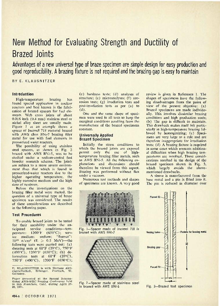
found special application in nuclear reactors and best known is the fabrication of brazed spacers for fuel elements. Web cross joints of about 0.016 inch (0.4 mm) stainless steel or nickel alloy sheet are usually made. Figure 1 as an example shows a spacer of Inconel 718 material brazed with AWS class BNi-7 brazing filler metal for use with fuel elements in pressurized water reactors.
The possibility of using stainless steel spacers, as shown in Fig. 2 brazed with AWS BNi-5, was to be studied under a sodium-cooled fast breeder research scheme. The joints are subject to a more severe environment than that which is found in pressurized-water reactors due to the higher operating temperature, the highly corrosive medium and the high dose of neutrons.
Before the investigations on the brazing filler metal were started, the question of a universal type of braze specimen was considered. The results of these considerations are described in the following paper.
Test Procedures
To enable brazed joints to be tested for their useability tinder the anticipated service conditions—temperature: 1200°F (650°C); service medium: sodium; "fluence": IO23 n/cm2 (E > 0.5 MeV)—the following tests were carried out: (a) shearing tests at 68°F (20°C), 750°F (400°C), 1200°F (650°C); (b) deformation tests at 68°F (20°C), 750°F (400°C), 1200°F (650°C);
E. KLAUSNITZER is with Siemens Akti-engesellschaft, Erlanger, Postfach, W. Germany.
Paper presented at the Second International AWS-WRC Brazing Conference held in San Francisco, Calif, during April 27-29, 1971.
(c) hardness tests; (d) analyses of structure; (e) microanalyses; (f) corrosion tests; (g) irradiation tests and post-irradiation tests as per (a) to (d) .
One and the same shape of specimen were used in all tests to keep the marginal conditions resulting from the manufacture of the brazed specimens constant.
Universally Applied Brazed Specimen
Initially the stress conditions to which the brazed joints are exposed permit only the use of high-temperature brazing filler metals, such as AWS BNi-5. All the following explanations and discussions should therefore be viewed from this aspect. Brazing was performed without flux under a vacuum.
Numerous test methods and shapes of specimens are known. A very good
* ' * I'S * I 1 * " ' * , * * 7y\\ •- "...
- - : _ * •• " J - ' - - - - , * : j * ,; • - : : , -
* • * •-.
• ., . ~ . *- - -
l i . . j . - i »**<. 1 - - .
i S i 1 1 1 81 1 1 » 1 I Fig. 1—Spacer made of Inconel
n
m i l l i
* 718 is brazed with AWS BNi-7
review is given in Reference 1. The shapes of specimens have the following disadvantages from the point of view of the present objective: (a) Brazed specimens are made individually. This involves dissimilar brazing conditions and high production costs; (b) The gap is difficult to maintain. This drawback makes itself felt particularly in high-temperature brazing followed by homogenizing; (c) Specimens are very large as a rule and are therefore inappropriate for irradiation tests; (d) A brazing fixture is required in some cases which presents additional difficulties when high brazing temperatures are involved. These considerations resulted in the design of the brazed specimen shown in Fig. 3, which largely avoids the above-mentioned drawbacks.
A sleeve is manufactured from the base metal and a pin is fitted into it. The pin is reduced in diameter over
Forced f i t - 1
Venting h o l e s - - ^
p
Brazing gap---^^
Forced fit-
Fig. 2—Spacer made of stainless steel is brazed with AWS BNi-5
1 u
<
/
Z
Pockets for brazing metal
Fig. 3—Brazed test specimen
454-s I O C T O B E R 1 9 7 1

Fig. 4—Typical appearance of a brazed test specimen (stainless steel brazed with AWS BNi-5)
Fig. 5—Eccentric position of the pin (stainless steel brazed with CPNM 2)
the greater part of its length so that the desired gap is obtained. The sleeve has several holes in opposite places, enabling the brazing gap to be vented and the brazing filler metal to be applied. Since the brazed specimen can be turned on a lathe, its manufacture is accurate, cheap and easily reproducible.
The specimen in this form is still not appropriate for the tests enumerated above. It has to be divided into 0.04-0.08 inch (1-2 mm) thick slices. These slices enabled all tests to be performed.
Brazed Test Specimen Sleeve and pin are degreased
(methanol in an ultrasonic bath) and then fitted together. The holes lying on one line parallel to the axis of the sleeve are then filled with brazing filler metal. The number and size of the holes should be chosen so as to ensure the brazing gap being completely filled with brazing filler metal. A vacuum induction furnace for indirect heating by means of a susceptor has proved suitable for the brazing operation. Brazing was carried out under the conditions prescribed by the manufacturer of the brazing filler metal or according to our own experience (heating rate, brazing temperature, holding time and cooling rate). The first examination after brazing is a visual test. If the specimens are metallically bright and the braze metal is visible both in the holes and at the ends of the sleeve and pin, then the specimens have been properly brazed. The specimen is then sliced, making sure that the cuts are taken exactly at right angles. About 20 slices 0.05 inch
Punch-
Pockets for brazing metal
Sleeve
Holder
Specimen
Fig. 7—Schematic of shearing tool
(1.2 mm) thick can be obtained from the specimen in Fig. 3.
About 40 test specimens have been made with different brazing filler metals and no rejects were found.
Basic Studies of Slices A few basic studies were carried
out to check whether the brazed specimen had the desired properties. It was found that the gap usually is constant over the entire length of the specimen. Figure 4 shows a typical brazed joint made with AWS BNi-5. An eccentric position of the pin was
Brazing gap
Venting slot'
Fig. 6—Improved design of brazed test specimen
occasionally encountered, as Fig. 5 shows.
This inaccuracy presumably is due
W E L D I N G R E S E A R C H S U P P L E M E N T ] 455-s
Punch
Specimen
-fJ8,05
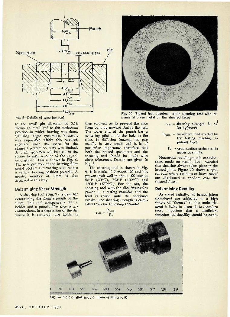
Fig. 8—Details of shearing tool
to the small pin diameter of 0.16 inches (4 mm) and to the horizontal position in which brazing was done. Utilizing larger specimens, however, was impossible within this research program since the space for the planned irradiation tests was limited. A larger specimen will be used in the future to take account of the experience gained. This is shown in Fig. 6. The new position of the brazing filler metal pockets and venting slots makes a vertical brazing position possible. A greater number of slices is also achieved in this way.
Determining Shear Strength A shearing tool (Fig. 7) is used for
determining the shear strength of the slices. This tool comprises a die, a holder and a punch. The slice is accommodated in a depression of the die where it is centered. The holder is
Fig. 10—Brazed test mains of braze metal
then screwed on to prevent the slice from bending upward during the test. The lower end of the punch has a centering pilot to fit the hole in the slice. In diffusion brazing, the gap usually is very small and it is of particular importance therefore that both the brazed specimens and the shearing tool should be made with close tolerances. Details are given in Fig. 8.
The shearing tool is shown in Fig. 9. It is made of Nimonic 90 and has proven itself well in about 100 tests at 68°F (20°C), 750°F (400°C) and 1200°F (650°C.) For the test, the shearing tool with the slice inserted is placed in a testing machine and the load is raised until the specimen breaks. The shearing strength is calculated from the following formula:
Tali F„
specimen after shearing test with re-on the sheared faces
TaB = shearing strength in ps (or kgf/mm2)
Pmax, = maximum load exerted by the testing machine in pounds force.
F0 = cross section under test in inches or (mm2).
Numerous metallographic examinations made on tested slices revealed that shearing always takes place in the brazed joint. Figure 10 shows a typical case where residues of braze metal are distributed at random over the sheared faces.
Determining Ductility As stated initially, the brazed joints
considered are subjected to a high degree of "fluence" so that embrittlement is liable to occur. It is therefore most important that a coefficient denoting the ductility should be estab-
+*? I 19 2 0 21 2 2 2 3 2 4 2 5 2 6 2 7 2 8 2 9
Fig. 9—Photo of shearing tool made of Nimonic 90
456-s | O C T O B E R 1 9 7 1

lished. No acceptable suggestions were found in the technical literature. To avoid any misunderstanding it should be pointed out that the proposition described in the following section is not fully satisfactory either but it appears to give reasonable results.
The test method for determining ductility is sketched in Fig. 11 and works as follows: The slice is placed on a soft metallic base (lead or aluminum) which has to be replaced for each new test. It is then forced into the base by means of a spherical punch in a testing machine. The slice adapts itself closely to the spherical punch. The merit of this method is that the brazed joint is evenly deformed irrespective of the braze efficiency (ratio of strength of braze metal to base metal). The degree of deformation depends on the diameter of the spherical punch and the thickness of the slice. The objective of the test is to define the degree of deformation at which the first incipient crack occurs in the brazed joint. The test is therefore started with a large punch, the diameter of which is then reduced in steps until an incipient crack is noticed.
In a test series using the same slice thickness, the diameter of the spherical punch can be used as a criterion of
Spherical punch
Specimen
Soft metallic base e.g. aluminium)
Fig. 11—Ductility testing tool
the deformation. Any other quantitative criteria are impossible to give since, as the degree of deformation rises, increasingly disturbing factors due to friction tend to develop. As is evident from Fig. 12, friction causes uneven deformation. But it is also seen how closely the slice adapts itself to the spherical punch. Figure 13 shows testing tools with different diameters. They are made of Nimonic 90 and were employed in more than 100 tests at 68°F (20°C), 750°F (400°C) and 1200°F (650°C). Further tests should reveal whether lubrication, the use of other materials for the base, or employment of cylindrical punches can improve the testing method.
Test Results An extensive test series was carried
out on different high-temperature brazing filler metals deposited on stainless steel. The brazing filler and base metals used are tabulated in Table 1. The brazing conditions are stated in Table 2.
Figure 14 shows typical micrographs displaying the characteristics of
the brazed joints. The hardness test results (Vickers test using a load of 0.050 kgf) are also shown.
All tests were carried out on slices 0.05 inches (1.2 mm) thick obtained from the brazed specimen in Fig. 3. The testing rate was constant 0.02 in/min (0.5 mm/min) in all tests.
The shear and ductility test results are shown in Tables 3 and 4 respectively. For the sake of comparison, the base metal was also shear tested after it had undergone two different heat treatments. These slices, like the brazed ones, were 0.32 inches (8 mm) in diameter and 0.05 inches (1.2 mm) thick and were taken from the same heat as the sleeves of the brazed specimens.
Discussion It is not the objective of this paper
to discuss the quality of the brazed joints but rather the effectiveness of the test methods. Nevertheless it should be mentioned that the micrographs of Fig. 14 display excellent brazed joints with, in some cases, complete diffusion of the brazing filler metal (BNi-5) into the base metal.
Fig. 13—Ductility testing tools Fig. 12—Appearance of specimens after ductility test. Diameter of punch is 40 mm (top), 16 mm (center) and 8 mm (bottom)
W E L D I N G R E S E A R C H S U P P L E M E N T I 457-s

fr - :
.J7^
• • . .
- ' • • -•'.-"" - •.* ''''• ' ^ r \ ^
•
* •,''."
195' 183 206
• 218 234 249 *321 til 208 186 182 177
1 ',-/.''
1 183 171 180 175
197 177 .1:78 174 183
• • • > : : . : . -
•*
• •
• '
f
~; * ,
•
A'- f. »
"̂Vi.---x ' ^ ^ ££tl.'.
y ~ - •'•
171 171. 180
. ' 180 177
. 4 9 9 'j 166' - 175 . 189
174
^ : : , i ^ ; . . i : . : . : j , : B ^ :
166 171 174 173 178 242 -183 169 163 174 172
• : • > -'
i . . -
. . . ' •
kv.- v..
• •
ijs .•*»
180 193
i " 204 190 201 24*9
192 202
i 202 202
183 192 199 18,5 184 J90 299
202 202 186-195 193
Fig. 14—Typical micrographs show structure and hardness of brazed joints. Top (left) BNi-6, (right) BNi-5; middle (left) Nicobraz 60, (right) CM60; bottom (left) CMNP, (right) CPNM2
458-s | O C T O B E R 1 9 7 1

Shearing Strength
Although the slices were taken at random from five brazed specimens, there is only a small amount of scatter in the various test results.
The shear strength measured on all specimens in which complete diffusion was observed is on the same order of magnitude as that of the base metal. Just a slight reduction was observed at high temperatures. An exception to this is brazing filler metal CPNM2 at 1200°F (650°C). The sharp drop in shear strength is accounted for by the different chemical compositions of this filler metal, the latter moreover being a nondiffusa-ble type of brazing filler metal.
The high shear strength and the small spread of the test results are surprising. One might conclude that there is an inherent error in the test method. What evidence can be produced to prove the effectiveness of the method described?
a) The high shear strength is plausible since optimum brazing conditions existed. b) Numerous metallographic examinations were undertaken to prove that the rupture under shear stress actually is in the brazed joint.
Table 1—Chemical Composition of Brazed Joints
Brazing filler metals*
BNi-6 BNi-5 Nicrobraz 60 CM 60 CMNP CPNM 2
Ni
Remainder Remainder Remainder
67 50.1 15
Si
— 10 8
10 11
- Corr Fe
— — — 3
30
position, % Mo P
— 11 — — — — — — 5.4 3.5
Cr
1 19 — 20 —
M •
— — 17 — — 10
Pd
— — — — — 20
Cu
— — — — — 55
* By AWS classification where applicable. Note: Base metal is X8 CrNiMo V Nb 16 13, W.Nr. 1-4988. Composit ion: 0.05% C, 0.5% Si ,
1.24% Mn, 16.8% Cr, 13.15% Ni, 0.79% V, 1.44% Mo, 0.67% Ta + Nb, remainder Fe.
Table 2—Brazing
Brazing filler metal
BNi-6 BNi-5 Nicrobraz 60 CM60 CMNP CPNIV12
Conditions
Brazing gap,/im
15 15 15 15 15 15
Vacuum, torr
5 X IO"6
5 X 10"' 5 X 10⁻⁶
5 X 10"6
5 X IO"6
5 X 10~6
Temperature, °F/°C
1920 (1050) 2190 (1200) 2050 (1120) 2150 (1175) 2100 (1150) 2190 (1200)
Temperature maintenance time, minutes
120 60 90 60 60 5
Table 3—Shear Test Results
Brazing filler metal
AWS BNi-6
AWS BNi-5
Nicrobraze 60
CM60
CMNP
CPNM2
Base metal
W. Nr. 1.4988 2 hr—1920° F (1050° C)
W. Nr. 1.4988 1 hr—2190° F (1200° C)
RT
Individual results
67,570(47.5) 68,140(47.9) 70,570 (49.6)
59,000(41.5) 68,280(48.0) 68,420 (48.1)
67,710(47.6) 68,430 (48.1) 61,180 (43.0)
67,000 (47.1) 71,280(50.1) 71,100(50.0)
72,700(51.1) 75,540(53.1) 71,570 (50.4)
66,850(47.0) 67,000 (47.1) 71,450 (50.3)
75,540 (53.2) 77,000(54.1) 74,700 (52.5)
71,100 (50.0) 71,100 (50.0) 71,280(50.1)
Mean value
68,710(48.3)
65,140 (45.8)
65,850 (46.3)
70,000(49.2)
73,250(51.5)
68,560(48.2)
75,850 (53.3)
71,100(50.0)
750° F (400° C)
Individual results
59,710(42.0) 59,140(41.6) 64,280 (45.2)
54,280 (38.2) 55,500 (39.0) 58,570 (41.2)
50,500 (35.5) 54,600 (38.4) 57,070 (40.1)
57,000 (40.0) 55,280 (38.8) 55,700(39.2)
60,930(42.8) 61,900(43.5) 61,300(43.1)
56,850(39.9) 56,930(40.0) 57,710(40.5)
55,780(39.2) 55,350 (38.9) 55,780 (39.2)
56,850(39.9) 55,640(39.1) 56,710 (39.8)
Mean value
61,000(42.9)
56,150(39.5)
54,020 (38.0)
55,900 (39.3)
61,300(43.1)
57,070 (40.1)
55,640 (39.1)
56,350(39.6)
1200° F (650° C)
Individual results
55,140(38.7) 53,710 (37.7) 53,850(37.8)
50,350 (35.4) 49,780(35.0) 50,070(35.2)
48,070 (33.8) 47,950(33.7) 48,070(33.8)
43,500(30.6) 49,780(35.0) 52,080 (36.6)
47,300(33.3) 53,350(37.5) 51,020 (35.8)
35,000 (24.6) 33,290(23.4) 35,570(24.9)
50,930(35.8) 52,210 (36.7) 51,640 (36.3)
51,640 (36.3) 52,780(37.1) 53,340(37.5)
Mean value
54,000(38.1)
50,070(35.2)
48,070(33.8)
38,520(34.1)
51,020(35.8)
34,710(24.4)
52,500(36.2)
52,500(36.9)
W E L D I N G R E S E A R C H S U P P L E M E N T | 459-s
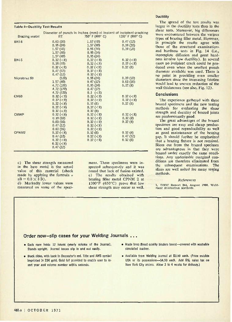
Table 4—Ductility Test Results
Brazing metal
BNi-6
BNi-5
Nicrobraz 60
CM60
CMNP
CPNM2
Diameter of punch in inches (mm) at instant of incipient cracking RT 750° F (400° C) 1200° F (650° C)
0.63 (16) 0.95 (24) 1.57 (40) 1.57 (40) 1.57(40) 0.32 (<8) 0.39 (10) 0.32 (<8) 0.47 (12) 0.47 (12)
(120) 1.57 (40) 4.72 (120) 4.72 (120) 4.72 (120) 0.32 (<8) 0.32 (<8) 0.32 (<8) 0.32 (<8) 0.32 (<8) 0.32 (<8) 0.39 (10) 0.63 (16) 0.47(12) 0.63 (16) 0.32 (<8) 0.47 (12) 0.32 « 8 ) 0.32 (<8) 0.47 (12)
1.57(40) 1.57 (40) 0.95 (24) 0.95 (14) 0.95(24) 0.32 (<8) 0.32 (<8) 0.32 (<8) 0.32 (<8) 0.32 (<8) 0.95(24) 0.47 (12) 0.95 (24) 0.47 (12) 0.3 (<8) 0.32 (<8) 0.32 (<8) 0.32(8) 0.32 (<8) 0.32 (8) 0.32 « 8 ) 0.32 (<8) 0.32 (<8) 0.32 « 8 ) 0.32 « 8 ) 0.32 (8) 0.32 (<8) 0.32 (<8)
0.47 (12) 0.39 (10) 0.39(10)
0.32 (<8) 0.32 « 8 ) 0.32 (8)
0.39 (10) 0.63 (16) 0.32 (8)
0.32 (<8) 0.32 (<8) 0.32 (8)
0.32 (<8) 0.32 (8) 0.32 (8)
0.32 (8) 0.47 (12) 0.32 (8)
c) The shear strength measured in the base metal is the actual value of this material (check made by applying the formula r
aB = 0.8 X SB) . d) Markedly lower values were measured on some of the speci
mens. These specimens were inspected subsequently and it was found that lack of fusion existed, e) The results obtained with brazing filler metal CPNM 2 at 1200°F (650°C) prove that low shear strength may occur as well.
Ductility
The spread of the test results was larger in the ductility tests than in the shear tests. Moreover, big differences were encountered between the various types of brazing filler metal. However, in principle the results agree with those of the structural examinations and hardness tests in Fig. 14 (i.e., incomplete diffusion and great hardness involve low ductility). In several cases no incipient crack could be produced even when the smallest punch diameter available was used. There is no point in providing even smaller diameters since the increasing friction would lead to uneven reduction of the wall thicknesses (see also, Fig- 12) .
Conclusions The experience gathered with these
brazed specimens and the new testing methods for evaluating the shear strength and ductility of brazed joints are predominantly good.
The great advantages of the brazed specimen are easy and cheap production and good reproducibility as well as good maintenance of the brazing gap. It should further be emphasized that a brazing fixture is not required. Slices cut from the brazed specimen are advantageous in that they were brazed under exactly the same conditions. Any undesirable marginal conditions are therefore eliminated from the subsequent examinations. The slices are well suited for many testing methods.
References 1. DMIC Repor t 244, August 1968, merit Evaluat ion Methods.
w e i d -
Order now-slip cases for your Welding Journals
• Each case holds 12 issues (yearly volume of the Journal).
Stands upright. Journal issues slip in and out easily.
• Black sides, with back in Decorator's red. Title and AWS symbol
imprinted in 23K gold. Gold foil provided to enable user to in
sert year and volume number within seconds.
Made from finest quality binders board-
simulated leather.
covered with washable
• Available from Welding Journal at $3.50 each. (Price outside
USA or its possessions—$4.50 each. Add 6% sales tax on
New York City orders. Allow 3 to 4 weeks for delivery.)
460-s | OCTOBER 1971